
Mechanical Properties of CaO–Al2O3–SiO2 Glass-Ceramics Precipitating Hexagonal CaAl2Si2O8 Crystals

Abstract
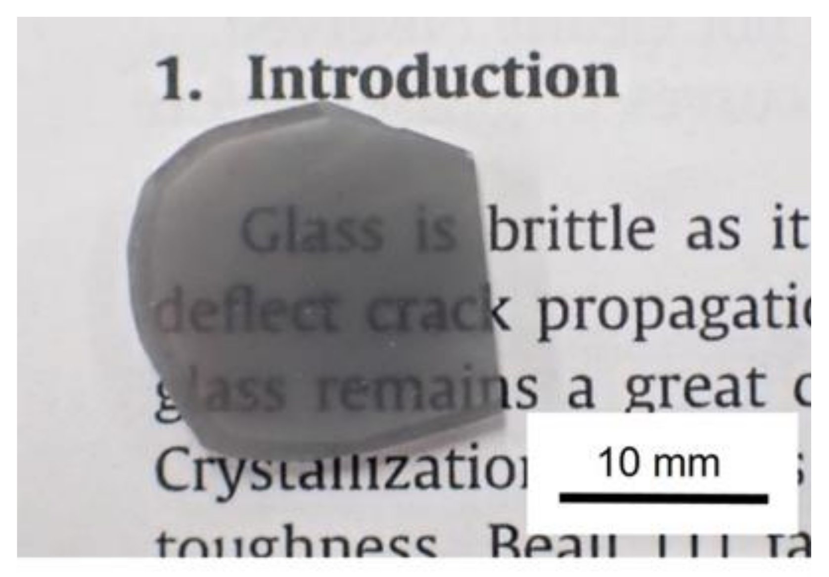
1. Introduction
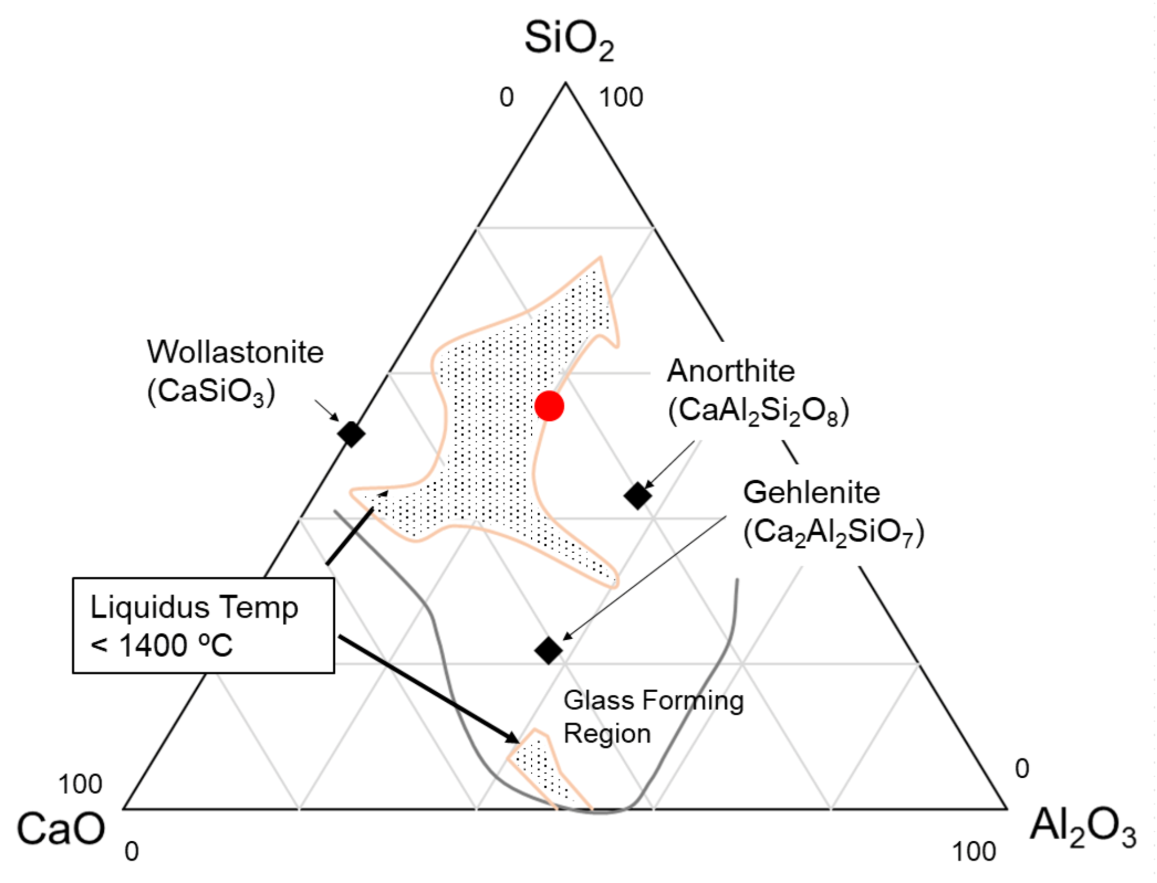
2. Materials and Methods
3. Results
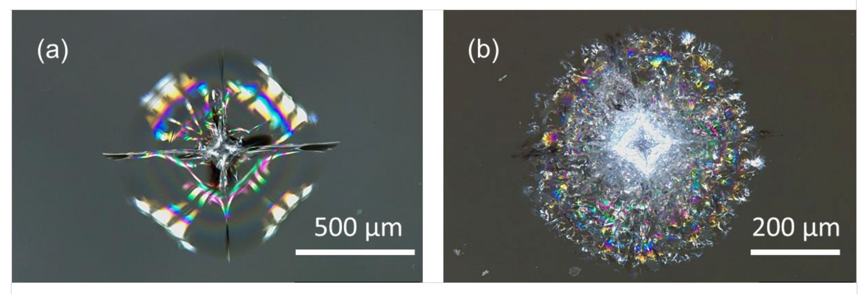
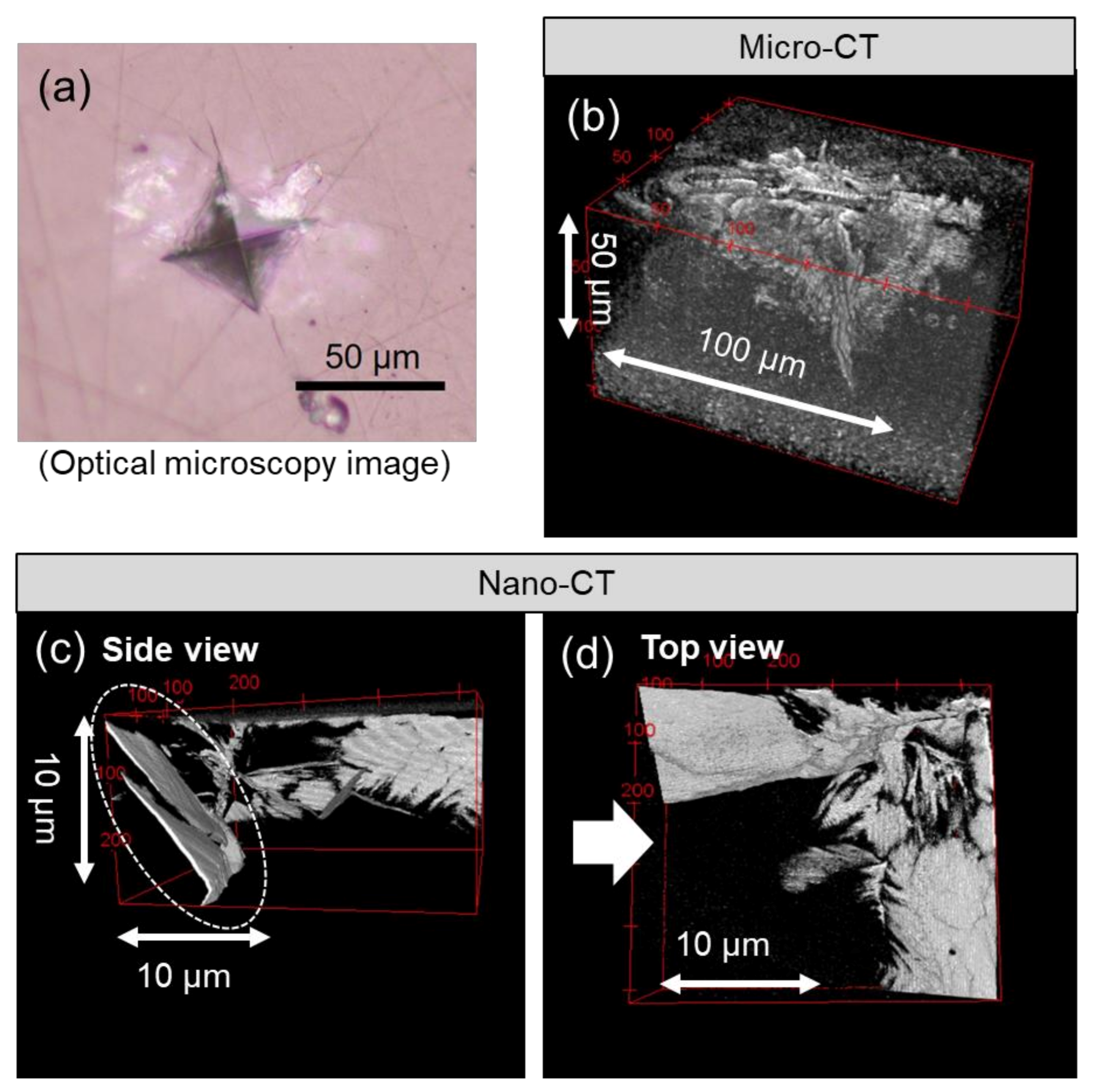
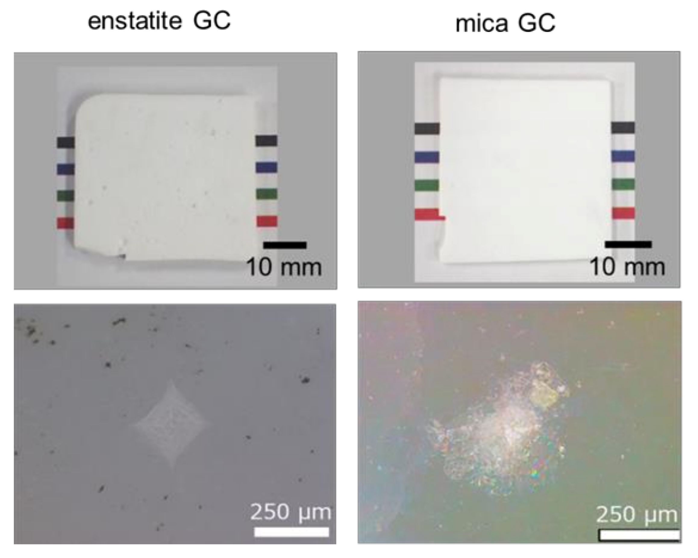
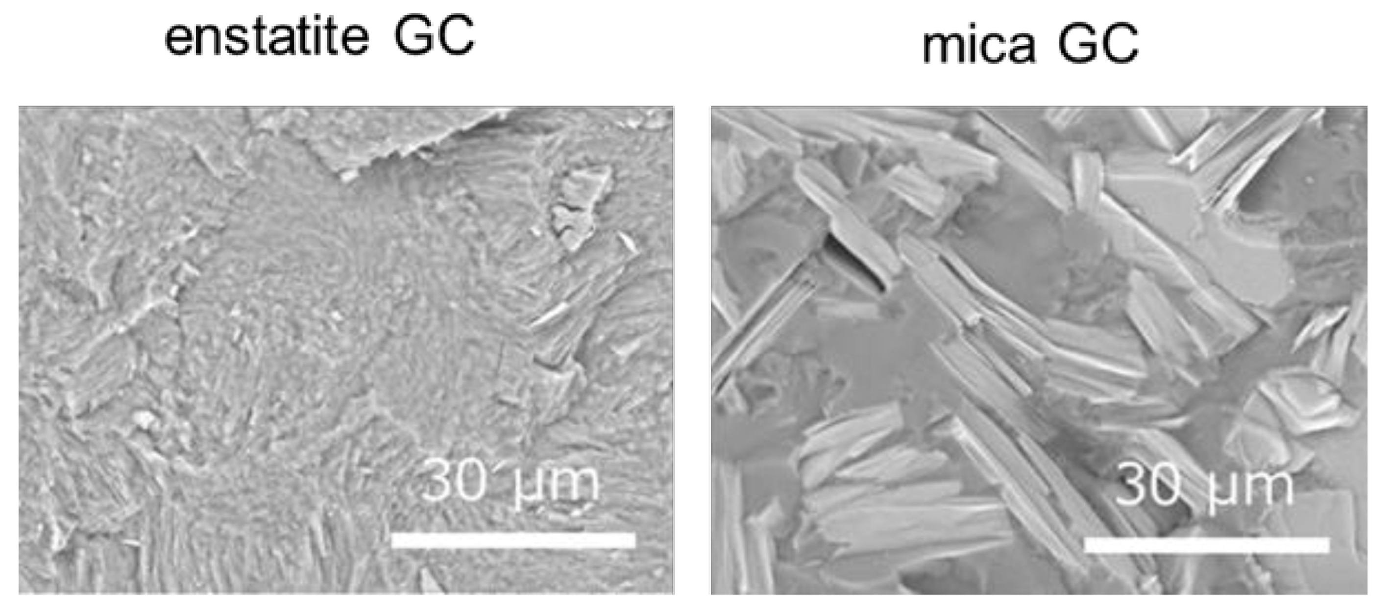
3.1. Characterization and Response to Vickers Indentation
3.2. Flexural Test
4. Discussion
5. Conclusions
6. Patents
Author Contributions
Funding
Acknowledgments
Conflicts of Interest
References
- Garvie, R.C.; Hannink, R.H.; Pascoe, R.T. Ceramic steel? Nature 1975, 258, 703–704. [Google Scholar] [CrossRef]
- Evans, A.G. Perspective on the development of high-toughness ceramics. J. Am. Ceram. Soc. 1990, 73, 187–206. [Google Scholar] [CrossRef]
- Hoagland, R.G.; Embury, J.D. A treatment of Inelastic deformation around a crack tip due to microcracking. J. Am. Ceram. Soc. 1980, 63, 404–410. [Google Scholar] [CrossRef]
- Evans, A.G.; Faber, K.T. Crack-growth resistance of microcracking brittle materials. J. Am. Ceram. Soc. 1984, 67, 255–260. [Google Scholar] [CrossRef]
- Faber, K.T.; Evans, A.G. Crack deflection processes-I. Theory. Acta Metall. 1983, 31, 565–576. [Google Scholar] [CrossRef]
- Faber, K.T.; Evans, A.G. Crack deflection processes-II. Experiment. Acta Metall. 1983, 31, 577–584. [Google Scholar] [CrossRef]
- Becher, P.F. Microstructural design of toughened ceramics. J. Am. Ceram. Soc. 1991, 74, 255–269. [Google Scholar] [CrossRef]
- Mazzei, A.C.; Rodrigues, J.A.; Pandolfelli, V.C. Alumina-mullite-zirconia composites obtained by reaction sintering Part II R-curve behavior. J. Mat. Sci. 2000, 35, 2815–2824. [Google Scholar] [CrossRef]
- Dai, Y.; Harmuth, H.; Jin, S.; Gruber, D.; Li, Y. R-curves determination of ordinary refractory ceramics assisted by digital image correlation method. J. Eur. Ceram. Soc. 2020, 40, 4655–4663. [Google Scholar] [CrossRef]
- Wiederhorn, S.M. Fracture surface energy of glass. J. Am. Ceram. Soc. 1969, 52, 99–105. [Google Scholar] [CrossRef]
- Vullo, P.; Davis, M.J. Comparative study of micro-indentation and Chevron notch fracture toughness measurements of silicate and phosphate glasses. J. Non-Cryst. Solids 2004, 349, 180–184. [Google Scholar] [CrossRef]
- Deubener, J.; Allix, M.; Davis, M.J.; Duran, A.; Höche, T.; Honma, T.; Komatsu, T.; Krüger, S.; Mitra, I.; Müller, R.; et al. Updated definition of glass-ceramics. J. Non-Cryst. Solids 2018, 501, 3–10. [Google Scholar] [CrossRef]
- Fu, Q.; Beall, G.H.; Smith, C.M. Nature-inspired design of strong, tough glass-ceramics. MRS Bull. 2017, 42, 220–225. [Google Scholar] [CrossRef]
- Pinckney, L.R.; Beall, G.H. Nanocrystalline non-alkali glass-ceramics. J. Non Cryst. Solids 1997, 219, 219–227. [Google Scholar] [CrossRef]
- Holland, H.; Beall, G.H. (Eds.) Glass-Ceramic Technology, 3rd ed.; Wiley: Hoboken, NJ, USA, 2019. [Google Scholar]
- Serbena, F.C.; Mathias, I.; Foerster, C.E.; Zanotto, E.D. Crystallization toughening of a model glass-ceramic. Act. Mat. 2015, 86, 216–228. [Google Scholar] [CrossRef]
- Beall, G.H. Chain silicate glass-ceramics. J. Non-Cryst. Solids 1991, 129, 163–173. [Google Scholar] [CrossRef]
- Pyroceram. In Glass-Ceramic Materials; Strnad, Z., Ed.; Elsevier: Amsterdam, The Netherlands, 1986; pp. 190–195. [Google Scholar]
- Beall, G.H.; Duke, D.A. Transparent glass-ceramics. J. Mater. Sci. 1969, 4, 340–352. [Google Scholar] [CrossRef]
- Soares, V.O.; Soares, F.C.; Oliveira, G.S.; Cruz, C.; Muniz, R.F.; Zanotto, E.D. Highly translucent nanostructured glass-ceramic. Ceram. Int. 2020. [Google Scholar] [CrossRef]
- Maeda, K.; Yasumori, A. Effect of molybdenum and tungsten oxides on nucleation and crystallization behaviors of MgO–Al2O3–SiO2 glasses. J. Non-Cryst. Solids 2015, 427, 152–159. [Google Scholar] [CrossRef]
- Maeda, K.; Yasumori, A. Effect of molybdenum and titanium oxides on mechanical and thermal properties of cordierite-enstatite glass-ceramics. J. Non-Cryst. Solids 2016, 434, 13–22. [Google Scholar] [CrossRef]
- Maeda, K.; Yasumori, A. Toughening of CaO-Al2O3-SiO2 glass by dmisteinbergite precipitation. Mater. Lett. 2016, 180, 231–234. [Google Scholar] [CrossRef]
- Maeda, K.; Iwasaki, K.; Urata, S.; Akatsuka, K.; Yasumori, A. 3D microstructure and crack pathways of toughened CaO–Al2O3–SiO2 glass by precipitation of hexagonal CaAl2Si2O8 crystal. J. Am. Ceram. Soc. 2019, 102, 5535–5544. [Google Scholar] [CrossRef]
- Inage, K.; Akatsuka, K.; Iwasaki, K.; Nakanishi, T.; Maeda, K.; Yasumori, A. Effect of crystallinity and microstructure on mechanical properties of CaO–Al2O3–SiO2 glass toughened by precipitation of hexagonal CaAl2Si2O8 crystals. J. Non-Cryst. Solids. 2020, 534, 119948. [Google Scholar] [CrossRef]
- Maeda, K.; Akatsuka, K.; Yasumori, A. Practical strength of damage resistant CaO-Al2O3-SiO2 glass-ceramic. Ceram. Int. 2021, 47, 8728–8731. [Google Scholar] [CrossRef]
- Cook, R.F.; Pharr, G.M. Direct observation and analysis of indentation cracking in glasses and ceramics. J. Am. Ceram. Soc. 1990, 73, 787–817. [Google Scholar] [CrossRef]
- Sakka, S.; Sakaino, T.; Takahashi, K. (Eds.) Glass Handbook; Asakura Shoten: Tokyo, Japan, 1975. [Google Scholar]
- Osborn, E.F.; Muan, A. revised and redrawn “Phase Equilibrium Diagrams of Oxide Systems,” Plate 1; Published by the American Ceramic Society and the Edward Orton, Jr., Ceramic Foundation, 1960. Phase Equilibria Diagram Online, American Ceramic Society. Available online: https://phaseonline.ceramics.org/ (accessed on 8 April 2021).
- Henry, J.; Hill, R.G. Influence of alumina content on the nucleation crystallization and microstructure of barium fluorphlogopite glass-ceramics based on 8SiO2•yAl2O3•4MgO•2MgF2•BaO part I Nucleation and crystallization behaviour. J. Mater. Sci. 2004, 39, 2499–2507. [Google Scholar] [CrossRef]
- Henry, J.; Hill, R.G. Influence of alumina content on the nucleation crystallization and microstructure of barium fluorphlogopite glass-ceramics based on 8SiO2•yAl2O3•4MgO•2MgF2•BaO part II Microstructure, microhardness and machinability. J. Mater. Sci. 2004, 39, 2509–2515. [Google Scholar] [CrossRef]
- Kübler, J. Fracture Toughness of Ceramics Using the SEVNB Method; round robin; VAMAS Report, No. 37; ESIS Document D2-99; EMPA: Dübendorf, Switzerland, 1999. [Google Scholar] [CrossRef]
- Takeuchi, A.; Uesugi, K.; Uesugi, M.; Yoshinaka, F.; Nakamura, T. Nondestructive multiscale X-ray tomography by combining microtomography and high-energy phase-contrast nanotomography. Microsc. Microanal. 2018, 24, 106–107. [Google Scholar] [CrossRef]
- Takeuchi, A.; Uesugi, K.; Uesugi, M.; Toda, H.; Hirayama, K.; Shimizu, K.; Matsuo, K.; Nakamura, T. High-energy X-ray nanotomography introducing an apodization Fresnel zone plate objective lens. Rev. Sci. Instrum. 2021, 92, 023701. [Google Scholar] [CrossRef]
- Okuma, G.; Watanabe, S.; Shinobe, K.; Nishiyama, N.; Takeuchi, A.; Uesugi, K.; Tanaka, S.; Wakai, F. 3D multiscale-imaging of processing-induced defects formed during sintering of hierarchical powder packings. Sci. Rep. 2019, 9, 11595. [Google Scholar] [CrossRef]
- Akatsuka, K.; Yasumori, A.; Maeda, K. Structure of crystalline CaAl2Si2O8 precipitated in a CaO–Al2O3–SiO2 glass-ceramic. Mater. Lett. 2019, 242, 163–165. [Google Scholar] [CrossRef]
- Anthony, J.W.; Bideaux, R.A.; Bladh, K.W.; Nichols, M.C. (Eds.) Handbook of Mineralogy; Mineralogical Society of America: Chantilly, VA, USA; Available online: http://www.handbookofmineralogy.org/ (accessed on 8 April 2021).
- Takeuchi, Y.; Donnay, G. The crystal structure of hexagonal CaAl2Si2O8. Acta Cryst. 1959, 12, 465–470. [Google Scholar] [CrossRef]
- Ito, J. High temperature solvent growth of anorthite on the join CaAl2Si2O8–SiO2. Contrib. Mineral. Petrol. 1976, 59, 187–194. [Google Scholar] [CrossRef]
- Abe, T.; Tsukamoto, K.; Sunagawa, I. Nucleation, growth and stability of CaAl2Si2O8 polymorphs. Phys. Chem. Miner. 1991, 17, 473–484. [Google Scholar] [CrossRef]
- Abe, T.; Sunagawa, I. Hexagonal CaAl2Si2O8 in a high temperature solution; metastable crystallization and transformation to anorthite. Miner. J. 1995, 17, 257–281. [Google Scholar] [CrossRef]
- Zolotarev, A.A.; Krivovichev, S.V.; Panikorovskii, T.L.; Gurzhiy, V.V.; Bocharov, V.N.; Rassomakhin, M.A. Dmisteinbergite, CaAl2Si2O8, a Metastable Polymorph of Anorthite: Crystal-Structure and Raman Spectroscopic Study of the Holotype Specimen. Minerals 2019, 9, 570. [Google Scholar] [CrossRef]
- Maeda, K.; Yasumori, A. Nucleation and growth of hexagonal CaAl2Si2O8 crystals in CaO–Al2O3–SiO2 glass. Mater. Lett. 2017, 206, 241–244. [Google Scholar] [CrossRef]
- Urata, S.; Takato, Y.; Maeda, K. Molecular dynamics investigation of the fracture mechanism of a glass-ceramic containing cleavable crystals. J. Am. Ceram. Soc. 2019, 102, 5138–5148. [Google Scholar] [CrossRef]
- Babelot, C.; Guignard, A.; Huger, M.; Gault, C.; Chotard, T.; Ota, T.; Adachi, N. Preparation and thermomechanical characterisation of aluminum titanate flexible ceramics. J. Mater. Sci. 2010, 46, 1211–1219. [Google Scholar] [CrossRef]
- Sato, I.; Ichikawa, Y.; Sakanoue, J.; Mizutani, M.; Adachi, N.; Ota, T. Flexible Ceramics in the System KZr2(PO4)3–KAlSi2O6 Prepared by Mimicking the Microstructure of Itacolumite. J. Am. Ceram. Soc. 2008, 91, 607–610. [Google Scholar] [CrossRef]


| Glass Ceramic Family | Major Crystalline Phase | Precursor Glass Compositions (wt%) | Flexural Strength, MPa | KIC, MPa∙m1/2 (Method) | Reference |
|---|---|---|---|---|---|
| Silicate | Lithium Disilicate | 74.2SiO2-3.54Al2O3-15.4Li2O-3.25K2O-3.37P2O5 | 217 | 3.3 (SENB) | [13] |
| Enstatite | 54SiO2-33MgO-13ZrO2 | 200 | 4.6 (CNSB) | [13] | |
| Enstatite + Spinel | 47.1SiO2-22.1Al2O3-16.9MgO-1.7ZnO-12.3TiO2 | 107 | 1.3 (CNSB) | [14] | |
| Aluminosilicate | β-spodumene | 65.1SiO2-20.1Al2O3-2.0B2O3-3.6Li2O-0.4Na2O-1.8MgO-2.2ZnO-4.4TiO2-0.4SnO2 | 100−150 | 1.0 (CNSB) | [13] |
| Leucite (Ivoclar IPS Empress®) | (59-63)SiO2-(19-23.5)Al2O3-(10-14) K2O-(3.5-6.5) Na2O- (0-1)B2O3- (0-1)CeO2-(0.5-3)CaO-(0-1.5) BaO-(0-0.5)TiO2 | 110−185 | 1.3 (SEVNB) | [15] | |
| Cordierite (Corning 9606) | 56.1SiO2-19.8Al2O3-14.7MgO-8.9TiO2-0.3As2O3-0.1CaO-0.1Fe2O3 | 200 | 2.2 (CNSB) | [13] | |
| Fluorosilicate | Mica (Macor) | 47.2SiO2-8.5B2O3-16.7Al2O3-14.5MgO-9.5K2O-6.3F | 94 | 1.53 (SEVNB) | [13] |
| Canasite | 57SiO2-2Al2O3-11CaO-13.0CaF-8.0Na2O-9.0K2O | 300 | 5.0 (CNSB) | [13] | |
| F-K-Richiterite | 67.1SiO2-1.8Al2O3-14.2MgO-4.7CaO-3.0Na2O-4.8K2O-0.75Li2O-0.3BaO-1.0P2O5-0.2Sb2O3-3.5F | 220 | 3.2 (CNSB) | [13] |
| Enstatite | Mica | |||
|---|---|---|---|---|
| Reference | [17] | [30,31] | ||
| Glass Composition wt% | SiO2 | 58.0 | SiO2 | 44.6 |
| Al2O3 | 5.4 | Al2O3 | 14.2 | |
| Li2O | 0.9 | MgF2 | 13.0 | |
| MgO | 25.0 | MgO | 14.0 | |
| ZrO2 | 10.7 | BaO | 14.2 | |
| Total | 100 | Total | 100 | |
| Melting Conditions /temp., hours | 1550 °C, 1 h | 1400 °C, 1 h | ||
| Heat Treatment /temp., hours | 800 °C, 2 h | 655 °C, 1 h | ||
| 1200 °C, 4 h | 1175 °C, 8 h | |||
Publisher’s Note: MDPI stays neutral with regard to jurisdictional claims in published maps and institutional affiliations. |
© 2021 by the authors. Licensee MDPI, Basel, Switzerland. This article is an open access article distributed under the terms and conditions of the Creative Commons Attribution (CC BY) license (https://creativecommons.org/licenses/by/4.0/).
Share and Cite
Maeda, K.; Akatsuka, K.; Okuma, G.; Yasumori, A. Mechanical Properties of CaO–Al2O3–SiO2 Glass-Ceramics Precipitating Hexagonal CaAl2Si2O8 Crystals. Crystals 2021, 11, 393. https://doi.org/10.3390/cryst11040393
Maeda K, Akatsuka K, Okuma G, Yasumori A. Mechanical Properties of CaO–Al2O3–SiO2 Glass-Ceramics Precipitating Hexagonal CaAl2Si2O8 Crystals. Crystals. 2021; 11(4):393. https://doi.org/10.3390/cryst11040393
Chicago/Turabian StyleMaeda, Kei, Kosho Akatsuka, Gaku Okuma, and Atsuo Yasumori. 2021. "Mechanical Properties of CaO–Al2O3–SiO2 Glass-Ceramics Precipitating Hexagonal CaAl2Si2O8 Crystals" Crystals 11, no. 4: 393. https://doi.org/10.3390/cryst11040393
APA StyleMaeda, K., Akatsuka, K., Okuma, G., & Yasumori, A. (2021). Mechanical Properties of CaO–Al2O3–SiO2 Glass-Ceramics Precipitating Hexagonal CaAl2Si2O8 Crystals. Crystals, 11(4), 393. https://doi.org/10.3390/cryst11040393