Review

Non-Mechanical Beam Steering with Polarization Gratings: A Review

Boulder Nonlinear Systems, Inc., 450 Courtney Way, Lafayette, CO 80205, USA
*
Author to whom correspondence should be addressed.
Crystals 2021, 11(4), 361; https://doi.org/10.3390/cryst11040361
Submission received: 15 February 2021 / Revised: 19 March 2021 / Accepted: 24 March 2021 / Published: 30 March 2021
(This article belongs to the Special Issue Liquid-Crystal Polarization Gratings)

Abstract

:
Polarization gratings (PGs) enable a novel architecture for dynamic non-mechanical steering of light over large angles and with large clear apertures. This beam steering approach has many applications in active sensing and optical communications. In this review, we describe some of the defining characteristics of this beam steering architecture and highlight several applications of the technology.

Graphical Abstract

1. Introduction

Dynamic optical beam steering is critical to many optical technologies, such as laser radar (lidar), laser illuminating beacons and designators, and free-space optical communications. To date, commercial beam steering technologies have been dominated by mechanical systems, such as gimbals, mirror galvanometers, and rotating prisms. However, the past thirty years have seen significant development in non-mechanical alternatives as a way to reduce size, weight, and power demands while improving robustness [1,2].
In the early 2000’s, interest increased in a variety of non-mechanical and low-mechanical beam steering approaches to reduce the size, weight and power (SWaP) requirements of electro-optic-based systems such as long-range lidar for drone platforms and free-space optical links for satellite-to-satellite communications. For these types of systems, larger aperture optics are preferred to reduce the performance and SWaP requirements of critical system components such as the laser source. Larger apertures reduce the divergence of a transmitter’s beam and allow a receiver to collect more light from a specific direction, thus increasing collected signal and reducing noise from background radiation. The improvement in optical gain and resolution/directivity is frequently advantageous in relation to other system tradeoffs, except when scanning the system. Mechanically steering large-aperture optics introduces significant SWaP issues for small platforms, as well as presenting increased reliability and maintenance issues. Therefore, new technologies were sought to find a low-SWAP, non-mechanical (or solid state) approach that could provide wide-angle steering for larger optical apertures (i.e., a non-mechanical scanner with a large angle-aperture product).
As we will show, polarization gratings (PGs) offer an angle-aperture product comparable to mechanical systems and larger than most non-mechanical and solid-state approaches, including acousto-optic (AO), electro-optic (EO), optical phased array (OPA), EO polymer/liquid crystal (LC) waveguides and MEMS devices. The angle-aperture product, also known as the Lagrange invariant, is an optical constant that a beam steerer provides. The nature of the invariant dictates that the maximum scan angle can be traded for aperture size through optical magnification. For example, a MEMS scanner with a 1-mm mirror capable of scanning over a 60° field of regard in two dimensions (2D) can be scaled through magnification to emulate a 1-cm aperture steered over a 6° field of regard. However, a 1-cm aperture is not sufficient for most long-range detection applications and 6° 2D scanning is not a large field of regard compared to mechanical systems. As a result, an important aim of non-mechanical beam steering development has been to achieve an angle-aperture product that supports steering apertures of >5 cm over as large a field of regard as possible with high efficiency.
As research in this field began, there were only a few non-mechanical options that theoretically could provide sufficient angle-aperture product. One option was to use segmented, birefringent solid crystal elements (such as LiNbO3 or YVO4) to form a large-aperture, polarization-controllable beam deflector and then stack these deflector stages together with EO-switches to form a discrete (or digital) beam scanner [2]. This approach is limited by the size, weight, and cost of the resulting beam deflector elements when scaled to sizable apertures. Additionally, significant beam walk-off results from the thickness of the individual deflector elements. This beam walk-off effectively reduced the scanner aperture for larger steer angles, which is undesirable. Another approach used volume Bragg gratings written in photo-thermal-refractive glass. This approach used LC OPAs to steer the beam into the volume grating structure, which then steered the beam into a new angle depending on the angle of arrival set by the OPAs [3,4]. This combination has produced discrete beam steerers that can steer over ±45° with good efficiency. This technique, however, requires the use of two large-aperture LC OPAs for discrete steering and four for quasi-continuous steering, by placing two more large-aperture OPAs at the end of the stack to fill in between the discrete angle deflections from the Bragg gratings. As with all LC OPAs, the steering efficiency rolled off to 60% in a few degrees [1,3,5]. This efficiency roll-off results from light coupling into sidelobes and zero-order leakage due primarily to phase wrapping (i.e, 0π to 2π transitions) required by blazed-grating phase profiles. These phase wraps must occur over a small spatial duration compared to the grating period and must provide a precise 2π phase shift or the resulting phase discontinuities produce sidelobes.
In the pursuit of a comparatively less expensive and more producible approach, there were also researchers working with patterned polymer plates that formed blazed grating structures that could be switched on or off through index matching with a LC layer to null out the grating [6]. These LC-based devices were composed of thin films and could be scaled to large apertures but relied on 0 to 2π phase wrapping. Since this was also a stacked element approach similar to the solid crystal approach discussed above, it did not take many stages to cause the steering efficiency to fall below 50% (i.e., −3 dB) if the diffraction efficiency of each deflector plate was not near 100%.
Pancharatnam-Berry phase modulation eliminates the need for phase wrapping in the grating profile, since the phase modulation continuously progresses with the rotation of the birefringent material’s optical axis [7,8]. Removal of phase discontinuities by eliminating the reset paved the way for PGs with near 100% diffraction efficiencies. Unlike optical path delay (OPD) modulators and Bragg gratings, this type of phase shift also made the deflector plates less sensitive to the steered light’s wavelength, because the phase shift depends only on the relative optic-axis orientation of the birefringent material. These theoretical advantages eliminated some difficult fabrication issues and provided a means for achieving a practical non-mechanical scanner with a large angle-aperture product. Early on, PG films had less steering efficiency than blazed grating films until the patterning and fabrication processes were improved to the point where practice started matching up with theoretical expectations [9]. At that point, the thought of cascading devices to form a digital beam scanner became a possibility, if the other losses such as Fresnel, LC scatter and electrode absorption could be reduced to workable levels.
Among non-mechanical beam steering approaches, polymer polarization gratings (PGs) offer a number of unique advantages [10,11,12,13]. In the following article, we will review the design and construction of non-mechanical steering devices using PGs, also known as Pancharatnam-Berry deflectors (PBD) or cycloidal diffractive waveplates (CDW). We aim to cover the relative strengths and weaknesses of the approach and highlight several demonstrations of the technology in different applications. Specifically, we present demonstrations of PG beam steering in three compelling use cases: a time-of-flight camera, a coherent Doppler lidar, and a midwave infrared (MWIR) broadband passive imager. While the scope of this review is aimed specifically at PG-based approaches to non-mechanical beam steering, the two reviews by McManamon et al. [1,2], provide a broader overview of non-mechanical optical beam steering, while the review by He et al. [5] provides comparison with other liquid crystal (LC)-based approaches. By viewing the larger beam steering topic with a wider lens, these reviews can serve to place the PG-based approaches in a broader context than provided here.

2. Non-Mechanical Beam Steering with PGs

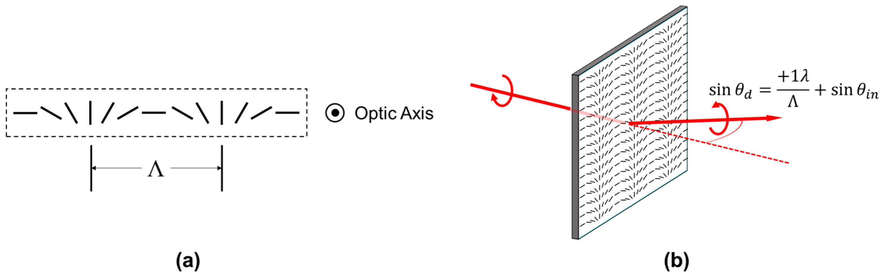
2.1. PG Fundamentals from a Beam Steering Perspective

Polarization gratings consist of a patterned birefringent material that exhibits a continuous in-plane rotation of the birefringence director (Figure 1). When patterned as a linear grating, such a structure produces a geometric phase delay across the aperture leading to diffraction given by
sin θ d = m λ Λ + sin θ i n
and [14]
η ± 1 = 1 2 ( 1 S 3 ) sin 2 ( π Δ n d λ )
Equation (1) is the familiar grating diffraction equation where θd is the diffraction angle, m is the diffracted order, λ is the wavelength of incident light, Λ is the period of the in-plane birefringence rotation, and θin is the incident angle. In Equation (2), η ± 1 is the diffraction efficiency into the ±1 orders, S’3 is the normalized Stokes vector indicating the ellipticity of the incident light polarization, and πΔnd/λ is the retardance of the birefringent layer.
Equation (2) shows that PGs offer the unique property of being able to couple 100% of incident light into either the +1 or −1 diffraction order when illuminated with circularly polarized light and the retardance is equal to a half wavelength. Moreover, PGs offer the important ability to select between these orders by controlling the handedness of incident polarization. Fortunately, such high diffraction efficiency is not merely a mathematical fiction and PGs with diffraction efficiency > 99.5% are routinely produced in real manufacturing environments (Figure 2a).
Such high diffraction efficiency is shared by volume Bragg gratings (VBG), however PGs possess the additional properties of being relatively thin and having a wide angle of acceptance. Specifically, typical polymer PGs are roughly 1–5 μm thick compared to 0.5–25 mm for VBGs [15]. With regard to acceptance angle, PGs exhibit peak diffraction efficiency at the angle of minimum deviation and a gradual roll-off of diffraction efficiency as incidence angle increases in either direction [13,16,17]. This roll-off is sensitive to the ratio of wavelength to grating pitch, and thus to angle, wherein gratings with larger diffraction angles experience greater roll-off. This roll-off and its asymmetry has been attributed to the change in effective retardance with increasing angle of incidence (AOI) [14]. For example, Figure 2a shows the angular response of a polymer PG designed to steer 1550 nm light with a diffraction angle for three different diffraction angles. In the ±6° PG case, the diffraction efficiency exceeds 97% over ±15° angle of incidence (AOI). By contrast, typical transmissive VBGs have acceptance angles of up to 10 mrad [15].
Other PG variations have been demonstrated that hybridize traditional PGs and VBGs to provide large diffraction angles. Depending on the details of design, these gratings include Polarization Volume Gratings (PVGs) [18], Bragg Polarization Gratings (BPGs) [19], and Dual-Twist Pancharatnam Phase Deflectors (DTPPDs) [20]. All of these PG variations rely on using chiral dopant to induce twist in the birefringence director along the optical axis. The twist provides an additional angled periodicity within the PG film that enhances diffraction efficiency at large angles. These approaches are promising for beam steering applications, as their efficiency at large diffraction angles (e.g., >40°) exceeds what can be realized with simple PGs. However, these approaches possess a preferred steering direction, instead of steering to both +1 and −1 orders, and tend to exhibit sharp decreases in efficiency at certain AOI. These traits present a challenge for designing non-mechanical steering systems that cover a wide angular field with a large number of steering angles.
In addition to large steering angles, the apertures achievable with PGs also make them particularly interesting for non-mechanical beam steering applications. Many alternatives, including liquid crystal on silicon (LCOS), electro-optic crystals, liquid crystal waveguides, micro-electro-mechanical systems (MEMS) mirrors, and electrowetting systems, are limited in aperture scalability [1]. The benefits of non-mechanical steering are particularly appealing when random access scanning is beneficial or for size, weight, and power (SWaP)-constrained large-aperture applications [21], where mechanical solutions are generally both bulky and power intensive.
The combination of these six properties:
  • near 100% diffraction efficiency;
  • polarization-selectable diffraction angle;
  • wide acceptance angle;
  • scalable aperture;
  • transmissive operation;
  • thin element thickness;
is specific to PGs and enable the layering of PGs with polarization handedness switches, such as liquid crystal (LC) variable retarders, to provide non-mechanical beam steering over wide angles with a thin, efficient, transmissive optic [12,13,17,22,23,24].
In practice, a non-mechanical beam steering assembly can be realized by index-matching and bonding together a polarization handedness switch and a PG as a functional unit, which we will refer to as a single steering stage. A single stage provides binary non-mechanical steering of light to the +1 and −1 diffracted orders of that grating. Multiple stages with progressively increasing PG diffraction angle can be index-matched and bonded together. In such an assembly, the diffraction angle of each grating either adds to or subtracts from the cumulative deflection angle of the light as it traverses the assembly depending on the state of each handedness switch. In this manner, PGs and polarization handedness switches produce non-mechanical beam steering in discrete steps over a potentially large field of regard, where the maximum number of steps is 2N, where N is the number of stages. For two-dimensional steering, stages can be oriented such that the PG fringes are at angles to one another. For example, a 90° rotation between stages produces a rectilinear grid of steering angles and a 120° rotation produces a hexagonally packed grid of angles.
For fabrication, numerous ways have been published to create the required PG alignment patterning [25,26,27], and the subsequent coating and curing of the reactive mesogen (i.e., LC polymer) are familiar processes in the fabrication of consumer LC devices. Therefore, this layered structure of laminated LC- and LC polymer-based components has the advantage of leveraging many fabrication processes developed for the consumer LC display industry, potentially reducing the barriers to inexpensive volume production.
The primary limitation of PG approach to non-mechanical beam steering is that the scanner is non-continuous. For many applications this is not a problem and three such applications are provided later in this paper. Where a system needs continuous steering, the PG approach can be paired with either a continuous non-mechanical device such as an LC OPA [10] or LC waveguide scanner [28] or a low-mechanical device such as a MEMS or fast steering mirror (FSM). Additionally, electrically tunable PGs with variable pitch have recently been demonstrated [29,30], as well as mechanically stretchable pitches [31], though early examples of both are still limited in aperture.
Thus far, we have focused the discussion on polymerized PGs. The PG alignment can also be realized in the liquid crystal phase [32,33]. When placed between transparent electrodes, such PGs can be electrically driven to a near homeotropic state, thus erasing the PG and transmitting incident light of either polarization handedness. These “active” PGs provide 3N potential steering angles, thereby enabling more steering angles with fewer stages [12]. For infrared applications, the increased layers of transparent electrodes mitigate the efficiency advantage of using fewer stages, however. It is also not practical to completely erase the grating due to surface anchoring of the LC molecules, reducing the efficiency of this state. Lastly, it is our experience that active PGs are susceptible to thermal drifts to efficiency, UV degradation, and alignment degradation over their lifetime that passive polymer PGs are immune to.

2.2. Optical Properties of PG-Based Non-Mechanical Steering Systems

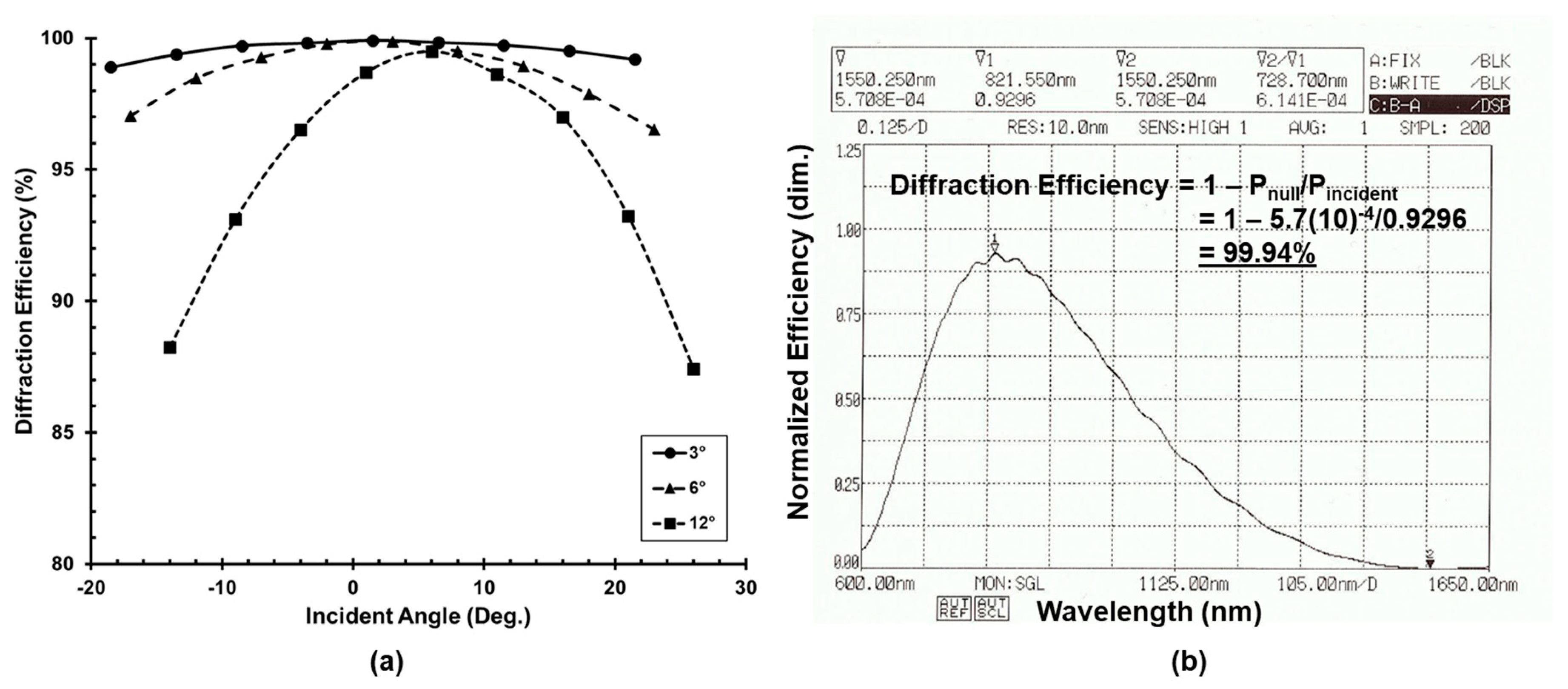
2.2.1. Spectral Properties

The useful spectral range of this technology is broad over optical wavelengths and limited primarily by material absorption constraints. In the UV, the primary challenge is the degradation of many LC-based polarization handedness switch architectures. Specifically, many nematic liquid crystals and polyimide alignment layers are known to degrade under UV illumination [34,35]. In the infrared, increasing absorption of many transparent conductors, such as indium tin oxide (ITO) and indium molybdenum oxide (IMO) gradually decreases per-stage efficiency as the design wavelength increases beyond 1 μm [36]. This is exacerbated by strong molecular vibration absorption bands in LC throughout the MWIR and long wave infrared (LWIR) for many liquid crystals [37], though these bands can be shifted through chemical modifications to the LC mixtures [38,39].
The spectral bandwidth of a specific design depends on the retardance error of both the PG and handedness switch over the desired spectrum. For example, Figure 2b displays the transmission spectrum of a PG fabricated for 1550 nm, where the null indicates the wavelength of peak diffraction efficiency. For this particular PG, 0.06% of incident light is transmitted into the zero order at 1550 nm and this leakage remains <3% over ± 105 nm. The PG design may be further achromatized with a dual-layer approach in which chiral dopants are used to generate opposing twist in each layer that serves to self-compensate chromatic dispersion in the geometric phase delay [40]. It is worth pointing out, however, that although the efficiency is achromatized, the steering angle still displays chromatic angular dispersion according to Equation (1).

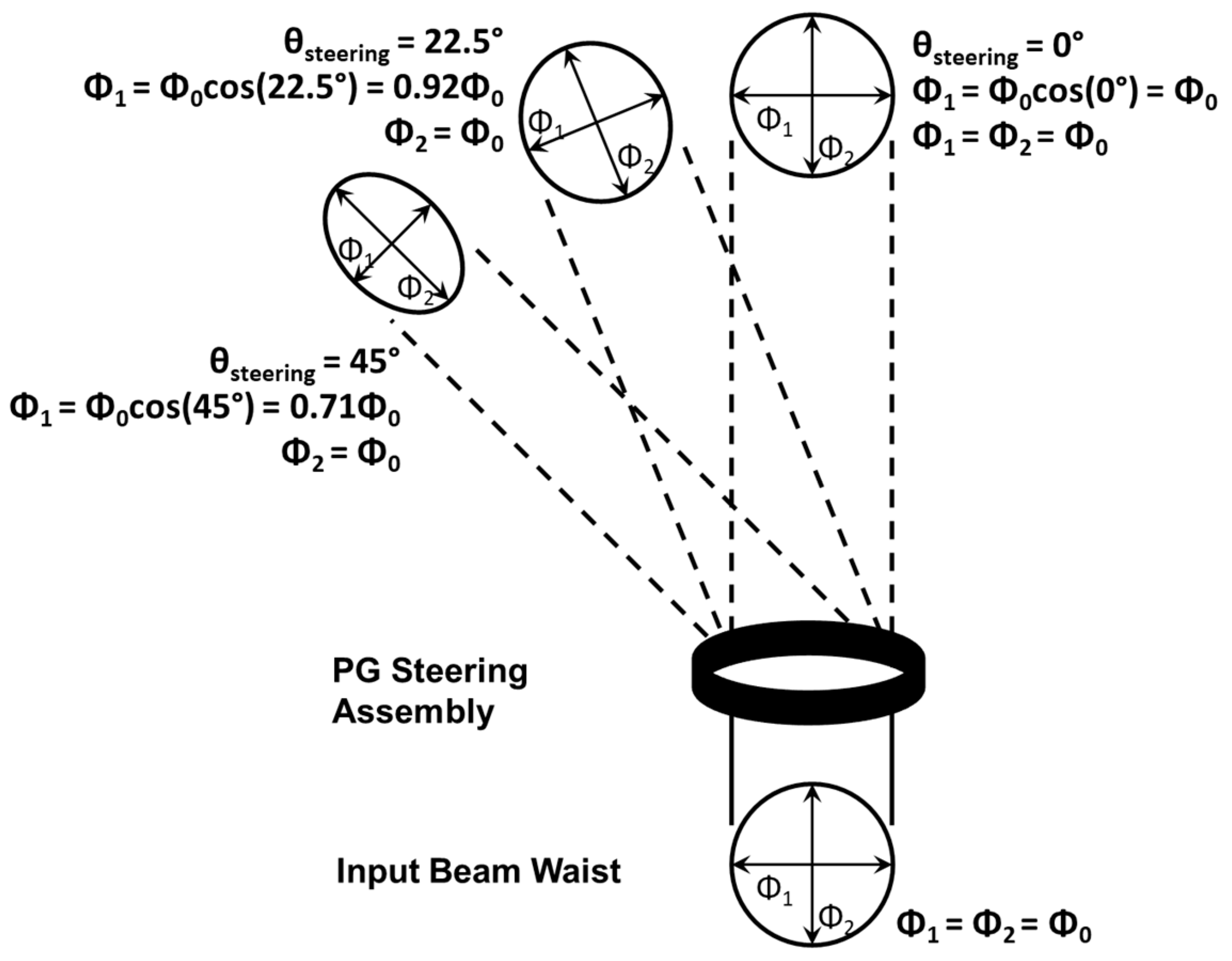
2.2.2. Steering Efficiency

Although individual PGs have peak diffraction efficiency approaching 100%, the total optical efficiency of the layered beam steering architecture also depends on the transmission efficiency and retardance accuracy of the handedness switches, scattering and absorption losses of the PGs, Fresnel reflections at interfaces, and the angular sensitivity of both handedness switches and PGs.
In the visible to SWIR spectrum, electronically controlled birefringence (ECB) variable retarder cells can provide transmission > 97% and enjoy a wide manufacturing base. Likewise, there exists a wide selection of inexpensive display glass and index-matching bonding agents suitable for assembling efficient PG-based steering systems over these spectral bands. Figure 3a shows a typical steering stage providing ±3.5° steering at 1550 nm with 96% total optical efficiency into the steered orders. For a full steering assembly with multiple stages, the angle-dependency of PG diffraction efficiency can become dominant and total steering efficiency decreases beyond ~96% per stage. For example, in Figure 3b, efficiency near the center is primarily a product of individual stage insertion loss for the five stages (i.e., 0.965 = 81%), but decreases with increasing steering angle due to AOI effects. Ultimately, all real diffractive beam steering systems will have a finite aperture that provides a corresponding envelope to the diffraction efficiency, resulting in decreased efficiency at higher angles. For active sensing this affect can be accounted for during processing of the return signal.

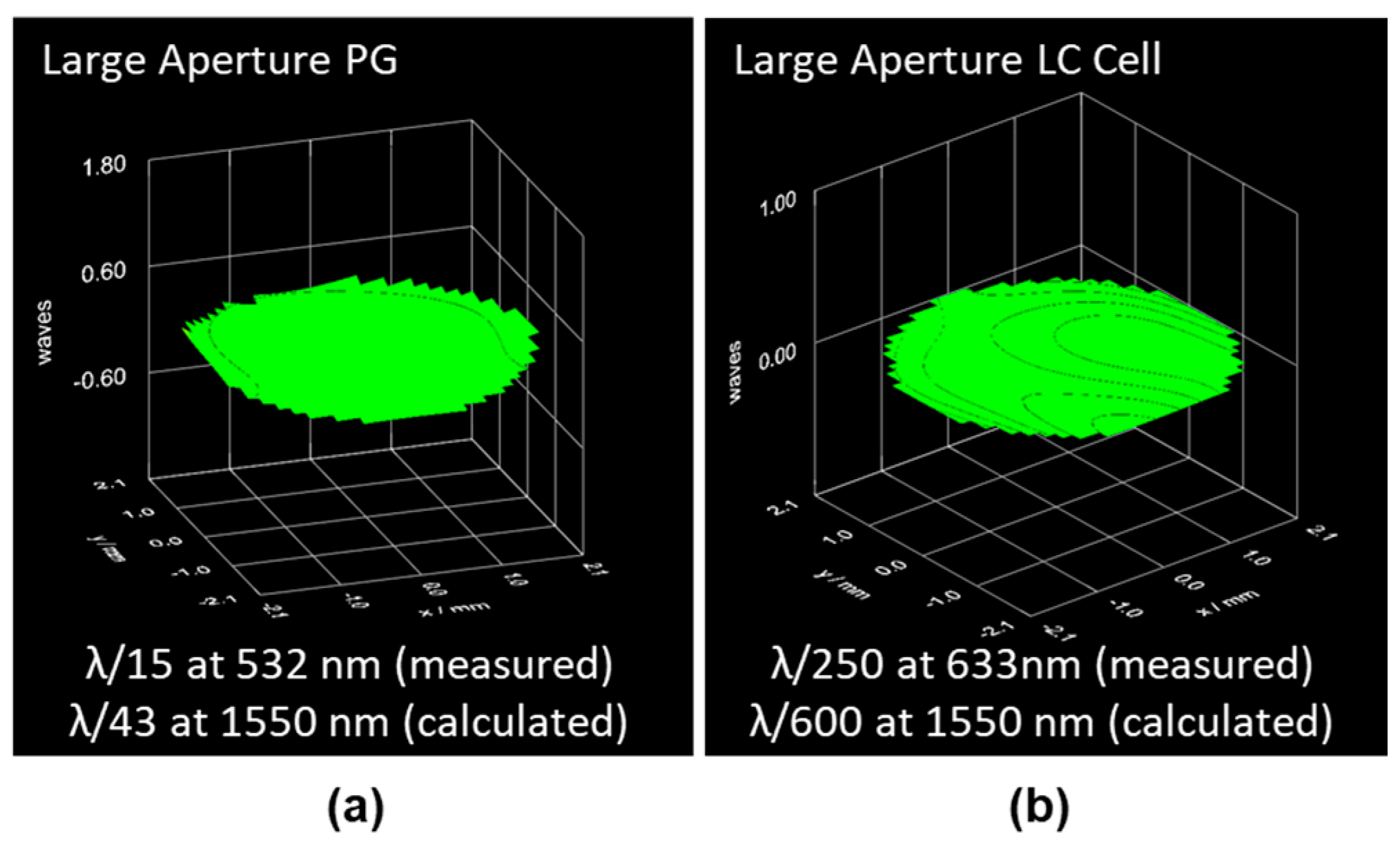
2.2.3. Wavefront Quality

Many beam steering applications of interest require high wavefront quality in the steered beam. This is particularly true for many coherent lidar and passive imaging applications. In a typical PG steering assembly, wavefront error can arise from the quality of the grating patterns, the uniformity of the LC cells, the flatness of the glass substrates, and stress-induced aberrations caused during assembly. Despite these varied potential sources of aberration, diffraction-limited performance is easily achieved in PG steering assemblies in real manufacturing environments. Figure 4a,b show wavefront measurements of a 10 cm clear aperture PG and LC handedness switch, respectively, measured at 633 nm by a Shack-Hartmann wavefront sensor. In both cases, the glass substrates used were inexpensive 2-mm thick Corning Eagle XG display glass.
Although diffraction-limited wavefront can be achieved with PG steering, it is important to note that steering a beam waist through a fixed planar aperture results in a foreshortening of the beam in the axis of steering (Figure 5). This is a geometric effect akin to the foreshortening that occurs when deflecting light with a prism at normal incidence to the entrance face. When using a single prism (or grating), this effect can be minimized by orienting the prism at the angle of minimum deviation. This is not possible with a PG steering assembly due to the varying output angles, and the resulting anamorphic magnification results in asymmetric divergence at increased steering angles. This is a trait shared by Risley prism [41] and planar phased array [42] (RF and optical) steering systems as well and for the same reasons. It should be noted that this effect does not introduce a wavefront error, but any wavefront variation will be magnified by the foreshortening, which for example can cause a spherical wavefront to become more cylindrical.

2.2.4. Switching Dynamics

Non-mechanical steering with layered PGs and polarization switches provides random-access beam repointing. As the PGs are passive elements, the transition time between angles is entirely dependent on the means of polarization switching. As mentioned earlier, the PGs provide binary steering in response to the two handedness states of circularly polarized light. Therefore, all switching solutions must provide a means to either maintain or flip handedness depending on their driven state. Solutions must also be thin, to permit the layering of multiple stages with manageable beam walk-off, and should be operable over a wide angular range. Owing to these last two constraints, liquid crystal devices offer several attractive solutions.
As previously mentioned, ECB cells using nematic liquid crystal provide a straightforward means of achieving switching in PG beam steering systems [13]. Such cells are well understood, simple to construct, and widely manufactured. In these cells, the response time is asymmetric, responding faster to an increasing drive voltage amplitude and relaxing more slowly. For true random-access scanning, the LC relaxation time becomes the limiting factor in beam repointing. This relaxation time is dependent largely upon the cell thickness and LC rotational viscosity [43,44]. Through the retardance relationship cited earlier, Δnd/λ, we observe that nematic LCs with high Δn permit thinner cell gaps and thus faster switching for a fixed wavelength. Similarly, longer wavelengths necessitate thicker cell gaps and, thus, slower switching for a given LC. In reality, this dependence on wavelength is exacerbated because most nematic liquid crystals exhibit decreasing Δn with increasing wavelength.
Through viscosity, temperature also impacts the switching speed of ECB-based PG steering systems. While this dependence dictates that high-speed LC devices must be maintained within a desired operating temperature range, it also enables the application of heat to improve device speed [44]. For example, half-wave retardance ECB cells built for 915 nm illumination, and using LC similar to that described in Gauza et al., can achieve <700 μs relaxation (Figure 6) when operating at a temperature of 65 °C and using the transient nematic effect (TNE) [45]. More generally speaking, high birefringence, low viscosity, nematic LC can provide relaxation times around 0.5–5 ms through the VIS–SWIR spectrums when both heating and TNE are utilized.
Many other architectures exist for LC-based polarization handedness switches. A few have benefits for particular applications and will be mentioned here. For example, Pi cells present a modified ECB alignment that reduces back flow within the cell, resulting in faster relaxation times particularly for thin (VIS spectrum) cells [46]. Polymer network nematic LC approaches have been demonstrated to significantly improve relaxation times though often at a penalty of increased scattering and/or drive voltages [47,48,49]. Likewise, ferroelectric LC (FLC) cells can provide fast switching in response to both rising and falling drive signals, however they provide in-plane switching and behave naturally as polarization rotators, rather than variable retarders. As such, more sophisticated switch assemblies are required to produce the desired handedness switch [50,51]. Both the polymer network nematic and ferroelectric LC approaches have applications in infrared switching, where the large cell gaps required for simple ECB switching otherwise result in 10’s to 100’s of millisecond relaxation times.
Ferroelectric liquid crystal switches can also offer advantages in viewing angle and achromaticity, however, FLC cells tend to be more difficult to yield in large apertures and more sensitive to mechanical shock and vibration [52]. For broadband applications, a twisted nematic (TN) cell can be used as a switchable polarization rotator for linearly polarized light and sandwiched between achromatic quarterwave retarders [53] at the expense of added complexity and slower switching.
Ultimately, the switching solution used becomes a key design factor in any PG steering assembly. Designs that aim to sample a large number of angles at a fast full frame rate place pressure on switching speed. However, systems with large numbers of angles, and thus many stages, are highly sensitive to optical efficiency of the switch design. These are frequently competing factors that require careful design optimization for a user’s specific application.

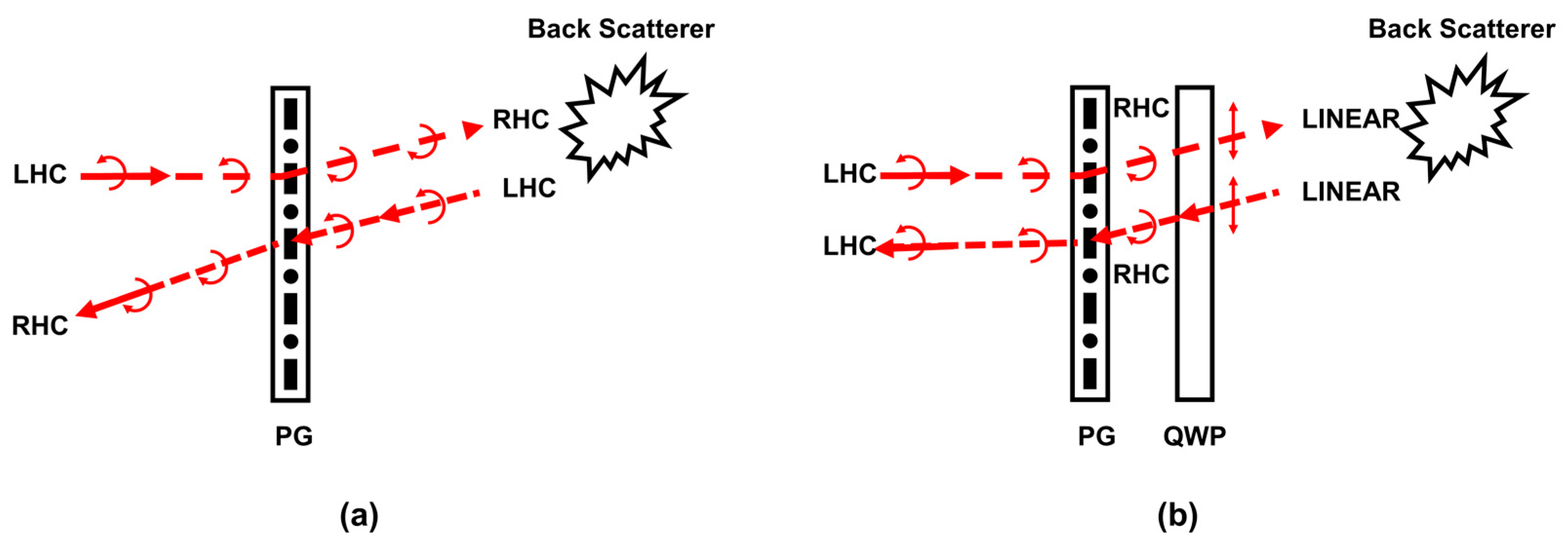
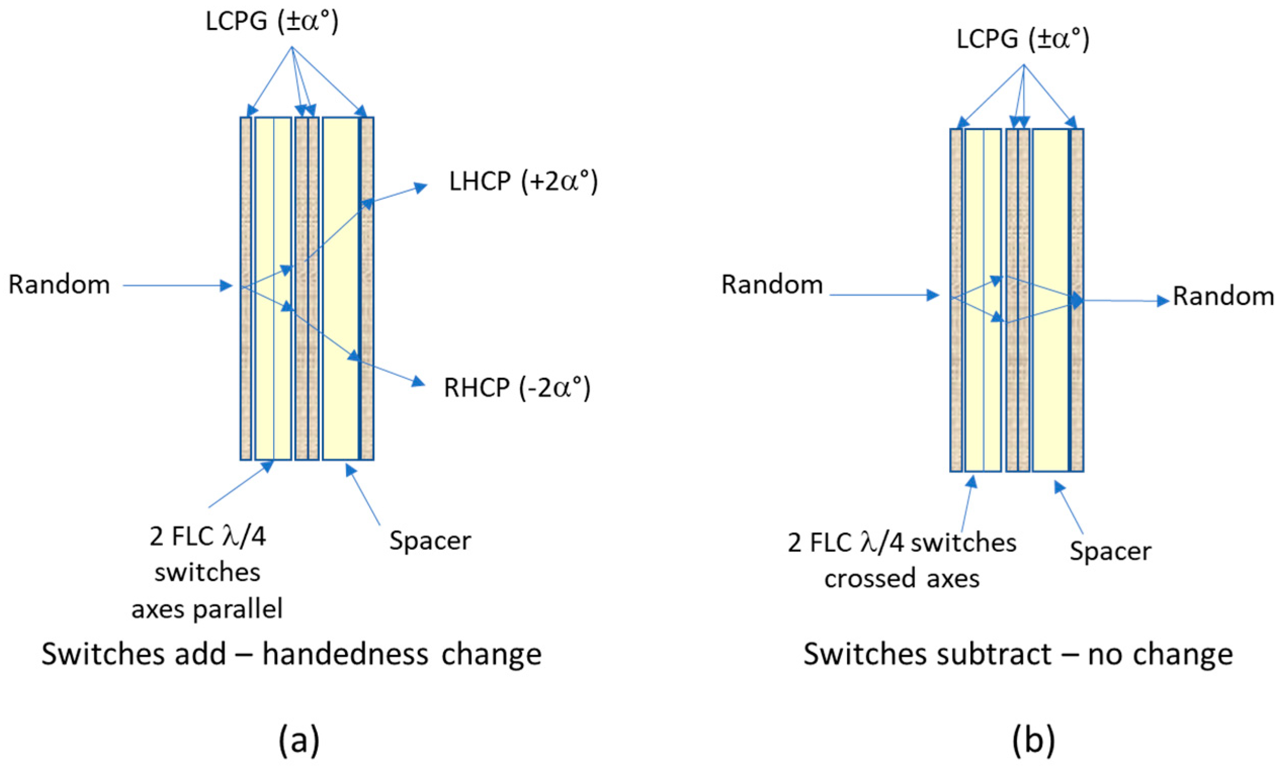
2.2.5. Polarization Considerations

The polarization-sensitivity of PG steering provides an additional constraint on potential applications. For active sensing applications that might not otherwise be polarization-sensitive, such as time-of-flight and flash lidar imaging, the varying degrees of depolarization of backscattered light from the target scene present an added loss factor [54,55]. As we show in Section 3.1, this loss factor is often significantly outweighed by the SNR benefits achieved from narrowing the instantaneous field of view (FOV) of such systems and using PGs to stitch the narrow FOVs to recapture the larger scene. Additionally, some applications benefit from increasing polarization sensitivity as a means to differentiate artificial objects or reject background radiation [56,57].
For applications, requiring bidirectional operation through a single PG steering assembly, special attention must be paid to polarization in both directions to ensure light follows a common path. From Equation (2), we note that the ±1 diffraction orders (i.e., steering angles) correspond to orthogonal polarization states. It is also worth briefly noting here that the halfwave retardance of the PG itself also serves to flip the handedness of the incident polarization. The result is that the various steering angles that emerge from a PG steering assembly are not uniform in polarization, but rather output polarization varies with steering angle. For bidirectional operation, the polarization must be identical in both directions for the light to follow a common path through the PG assembly (Figure 7a,b). As a result, where transmit and receive paths must be split off inside a system, they must do so without using polarization-based beam splitting.
For applications that rely on transmitting through a PG steering assembly and collecting the backscattered light through the same aperture, such as monostatic lidar, the handedness flip that occurs upon specular backscatter causes the polarization of the returning light to be in the incorrect polarization (Figure 7a). In such scenarios, it becomes important to convert the transmitted light into a linearly polarized state upon transmitting out of the PG assembly so that the polarization handedness flip on backscatter can be avoided (Figure 7b). This is especially true in polarization-sensitive applications, such as the coherent lidar shown in Section 3.2

3. Applications of Non-Mechanical Beam Steering with PGs

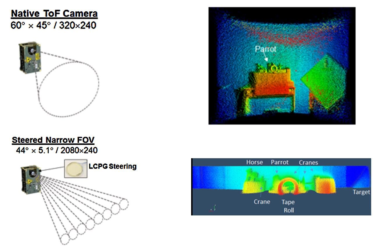
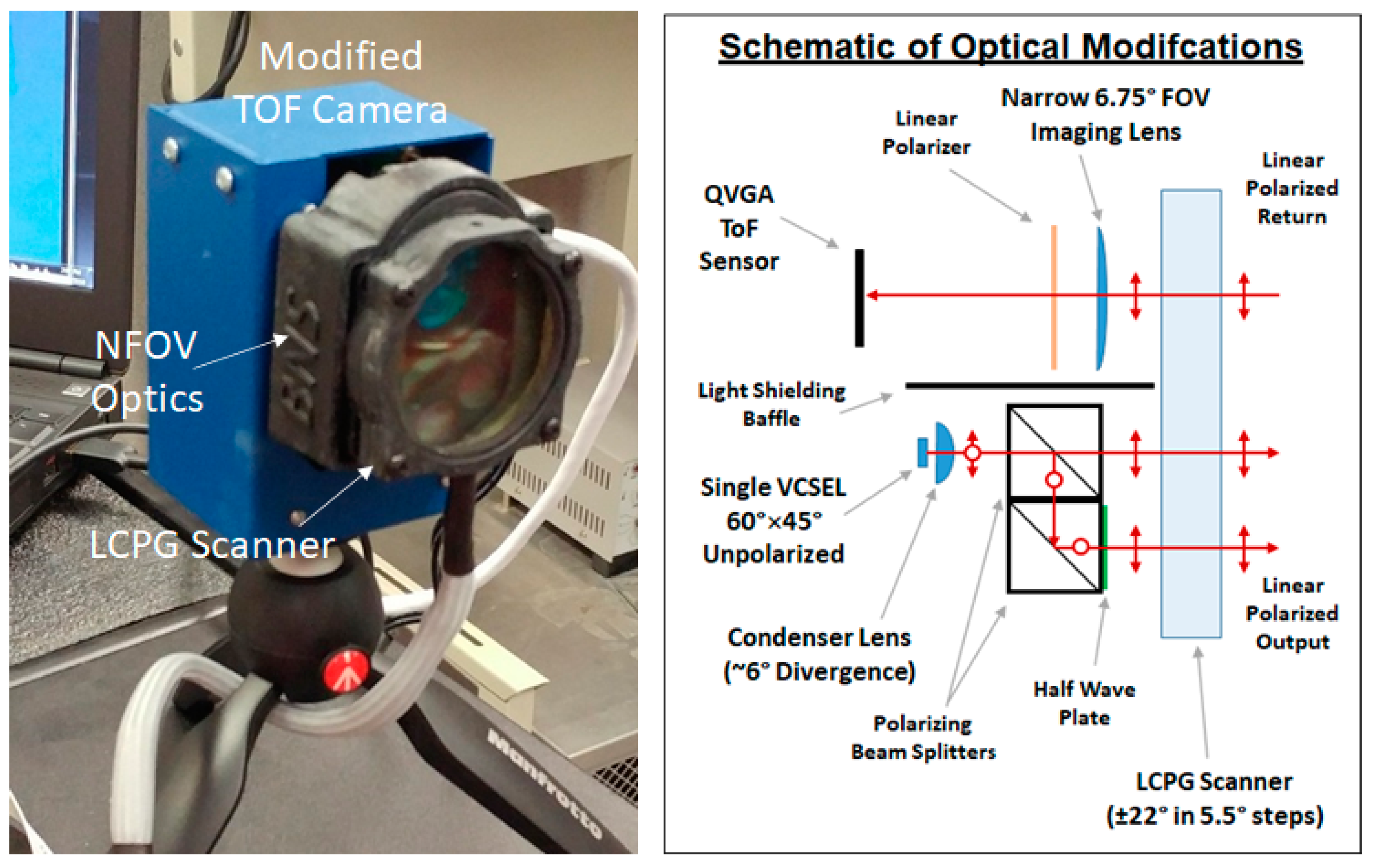
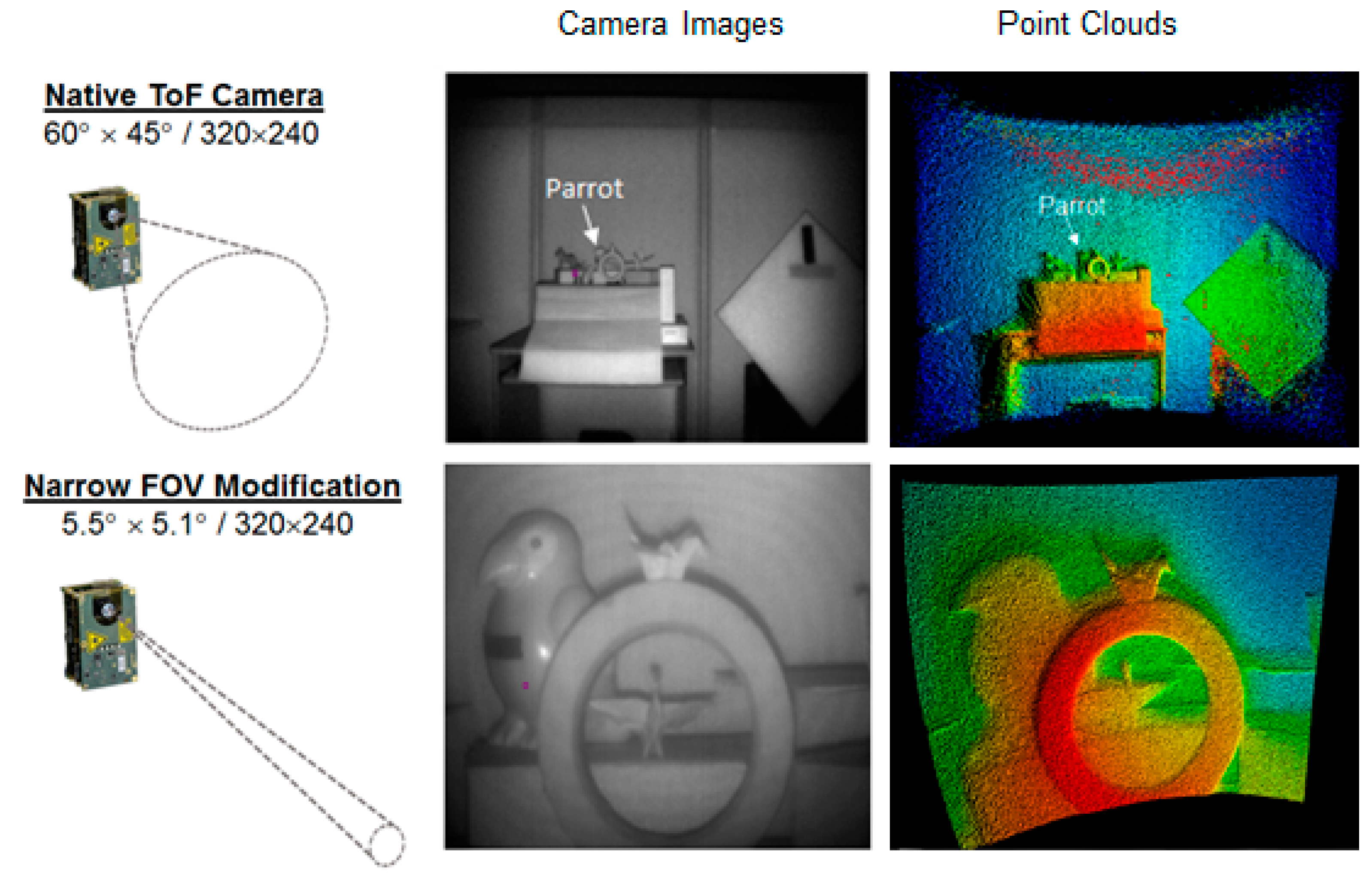
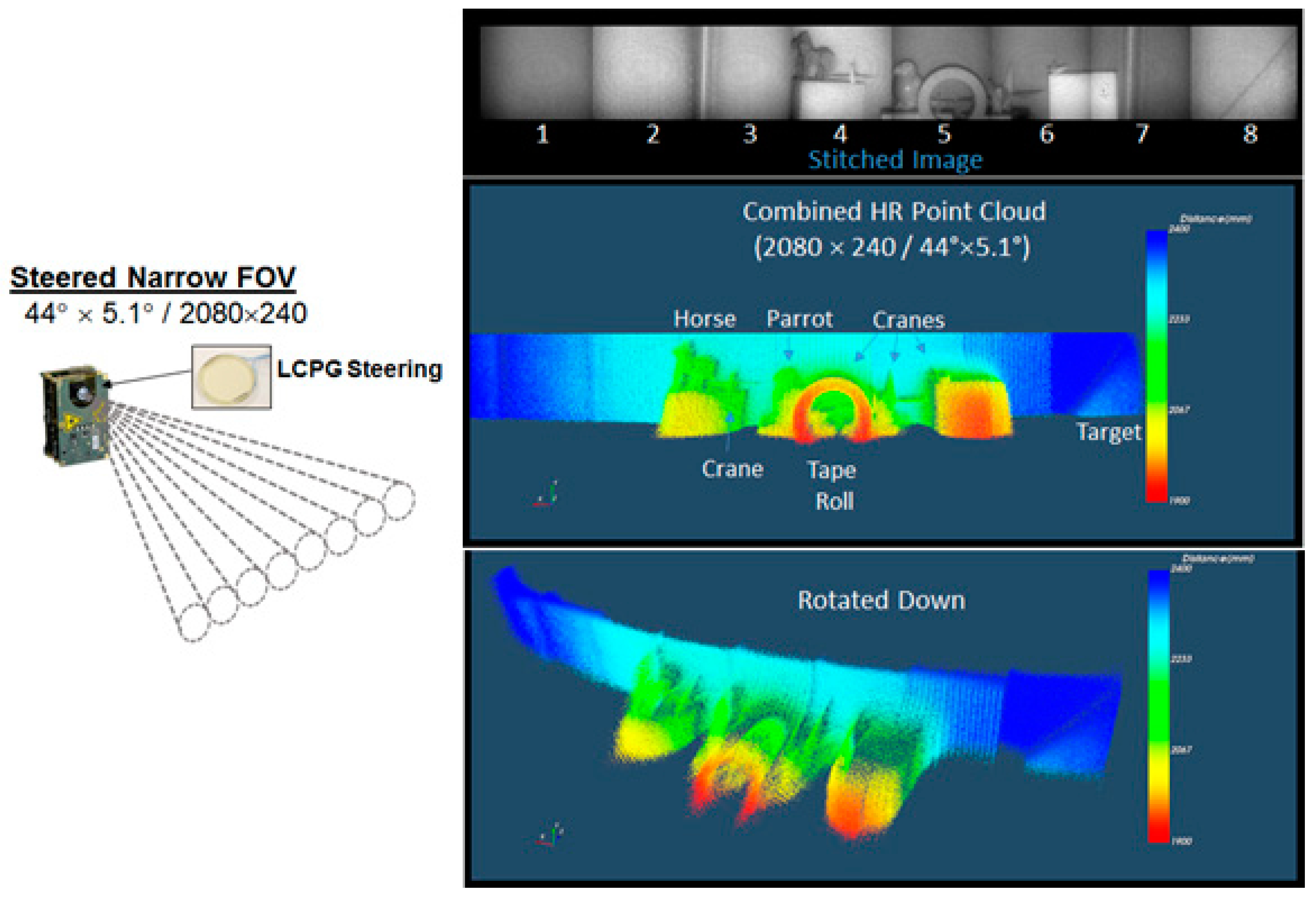
3.1. Tiling Fields of View in Time-of-Flight and Flash Lidar Sensors

Time-of-flight (TOF) three-dimensional (3D) imaging is one application that provides a complimentary fit for the PG steering technology. A TOF 3D imaging system generally illuminates a sizable area with modulated laser light and uses a focal plane array (FPA) to simultaneously detect the return from thousands of locations in the receiver’s field of view (FOV). Thousands of points, from a QVGA (320 × 240) TOF detector for example, produce a dense 3D point cloud, but the 3D image’s spatial resolution is low if the points are distributed over a reasonably wide field of view. High-resolution point cloud generation over a wide angle presents problems for a TOF camera (or flash lidar), since more spatial resolution generally means more pixels within the array and thus less return signal per detector element [58]. Additionally, wider view angles cause more ambient (background) light to be collected along with the TOF signal, which increases shot noise even if the ambient noise is rejected through electronic processing. These signal-to-noise issues along with size, weight, power, and cost constraints usually force a tradeoff of resolution for coverage. Fortunately, a TOF camera (or flash lidar) can provide higher resolution and better signal-to-noise ratio (SNR) by narrowing the FOV of the camera, and the PG scanner can step both the transmit beam and receiver FOV to gain back area coverage.
To examine this basic concept, we modified a commercial-off-the-shelf (COTS) QVGA TOF camera (EVK75123-60-850-1, Melexis) as shown in Figure 8. The modification was performed in three steps, which are represented in Figure 9 and Figure 10. The first step was to characterize the native TOF camera. The second step was to modify the camera optics to narrow the transmit beam and sensor FOV, and then to test the modified configuration. The third step was to add the scanner, measure system performance and finally splice the collected 3D data into a single point cloud. This modification sequence allowed us to compare the resolution and SNR improvement obtained in each step.
As comparatively shown in Figure 9, the native COTS TOF camera provides a 320 × 240 image over a 60° × 45° field of view or a 0.19° × 0.19° angular resolution, which is roughly the angular resolution of a person with 20/200 visual acuity. After modification of the camera’s optics, the sensor’s angular resolution improves to 0.02° × 0.02°, which is nearly the angular resolution of a person with 20/20 vision. For the images and point clouds shown in Figure 9 and Figure 10, the targets are approximately 2 m from the native and narrow-FOV TOF cameras. By narrowing the FOV, the increase in resolution magnifies the image and point cloud bringing out more detail for identifying objects. In addition to a resolution difference, the resulting point cloud from the native COTS camera has considerably more noise (i.e., more graininess with a few patches of out-of-place points spread over the plot). Depth variance/accuracy, as indicated by the roughness of the point clouds, is directly related to SNR.
To understand the various factors that contribute to SNR, it is necessary to look at the optical modifications made to narrow the camera’s FOV. First, the simplest method for narrowing the transmit beam of the camera is to block off three of the camera’s four VCSELs, which made it easy to use a single condenser lens to collect and nearly collimate the light from one VCSEL. Beam divergence was set to ~5.5°. Blocking off three of the VCSELs reduces the transmitted signal power by slightly more than a factor of four. A series of polarizing beam cubes and a halfwave plate are used to vertically polarize the unpolarized light from the VCSEL without discarding half of it. This polarization of the emitted light is required for efficient operation with the PGs.
The transmitter is aligned to flood the area seen by the receiver which has also been modified for a 5.5° FOV. The transmitted light reflected by the target is partially depolarized and some of this backscattered light is collected by a new narrow-angle one-inch receiver lens, which has approximately ten times the area of the original wide-angle lens. The received light passes through a cleanup polarizer, which serves to filter out sidelobes from the transmitter, and is focused onto the QVGA TOF FPA. The measured SNR improvement for the narrow-FOV image shown in Figure 9 is approximately 6.4 dB, which is close to our theoretical estimate of 7 dB. This estimate assumes approximately a 10× increase in aperture area, 4× decrease in output power, 2× decease in signal return due to polarization, and 4× decrease in shot noise due to using a polarizer to block half the ambient light and having a smaller detector angular subtense (DAS). This estimate does not account for Fresnel losses from individual components added to the system, which appears to add up to ~10% or another −0.5 dB for the modified camera.
Since the signal gain from using a larger aperture lens is mostly cancelled out by choosing to use 1/4th of the transmitter’s output power and using a cleanup polarizer at the receiver, the main SNR improvement is mostly due to collecting less ambient light, which reduces the shot noise. That is, the native camera collects approximately 18× more ambient light than the modified camera, which becomes a limitation for using wide-angle TOF cameras in outdoor applications. There are various options to further increase SNR, but each option presents a tradeoff. For example, with some added complexity it is possible to harness the light from more than one VCSEL to increase the transmitter’s output power, but it does not take much of an increase before the narrow beam becomes an eye hazard. A safer SNR improvement is to increase the receiver aperture. This type of SNR enhancement adds some size and weight, but modest size increases are easily accommodated by other parts of the system such as the scanner. The diameter of LCPG scanners can be extended to >20 cm if necessary.
It is obvious from Figure 9 that the overall wider FOV of the native camera provides more situational awareness capability. To gain back some of the angular coverage, the next step is to integrate the modified camera with a 3-stage, one-dimensional (1D) LCPG scanner, which steers the sensor’s transmitted beam and the received field of view over a 44° field of regard in eight 5.5° steps. As mentioned above, the transmitted light from the VCSEL is vertically polarized before entering the scanner. This light is converted to circularly polarized light by the first LC cell in the steering stack, which acts as a switchable quarterwave retarder. This light is then efficiently steered by the rest of the stack to the selected angle set by the halfwave LC switches in the stack. Another LC quarterwave retarder at the exit aperture of the stack converts the light back to a linear state. This stack arrangement steers the transmitted light to one view angle and steers the linearly polarized light reflected from that angle back on axis where it focused onto the camera’s FPA after it passes through a cleanup polarizer. It has been our experience that if the transmitter and receiver are properly aligned before the scanner is inserted into the system, the LCPG scanner maintains the alignment as it steers to any of the view angles.
Figure 10 shows a result from the modified camera after the 3-stage stack is integrated with the narrow-FOV camera. The camera captures eight high-resolution images as the 1D LCPG scanner steps across the field of regard. There is approximately a 0.8° overlap of the captured images to ensure continuous and uniform coverage across the field of regard. This angular overlap is 30 pixels. Therefore, the overlapping pixels are removed to stitch the eight images together to form a 2080 × 240 image with each image tile being 260 × 240. A point cloud is generated from the corresponding distance data, which can be rotated and analyzed as a 3D object.
The 3-stage scanner fabricated for this first prototype has a transmission of approximately 75% (or 2.5 dB round-trip loss), which is not optimized. With four LC cells and 4 PGs in the stack (where 2 PGs are used to form the largest steer angle), the transmission can be ~86% (3–4% per cell-grating pair). The additional loss in the prototype is mostly due to voltage-dependent back reflections observed while testing the LC cells, which can be significantly reduced by carefully selecting the cell gap to avoid the loss. To show this is the case, a new TOF camera is being developed, which uses an 8 × 8 scan pattern to extend the camera’s field of regard in two dimensions (2D). The 2D PG steering assembly, made to steer the camera’s FOV 48° in azimuth and 40° in elevation using 6° and 5° steps, respectively, is shown in Figure 11. This stack has 8 PGs and 7 LC switches and meets expectations at the design wavelength with an average transmission of 74% over the field of regard. Additionally, shown in Figure 11 are thinner PGs and LC cells built with 0.2 mm thick substrates, which can be used to reduce the size and weight of the stack for SWaP-sensitive applications.

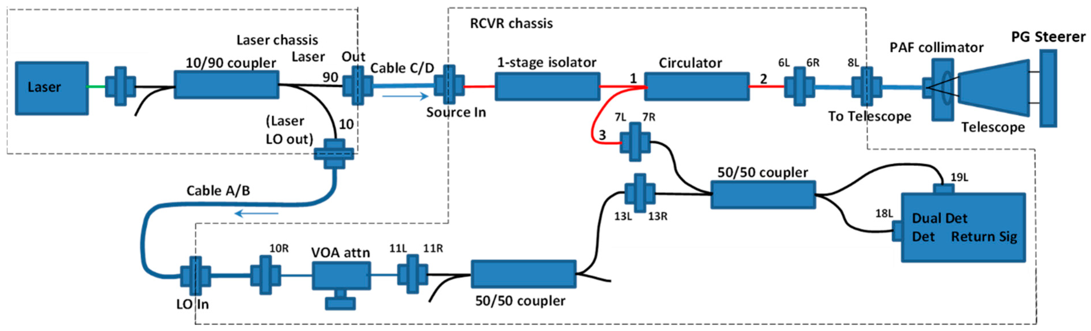
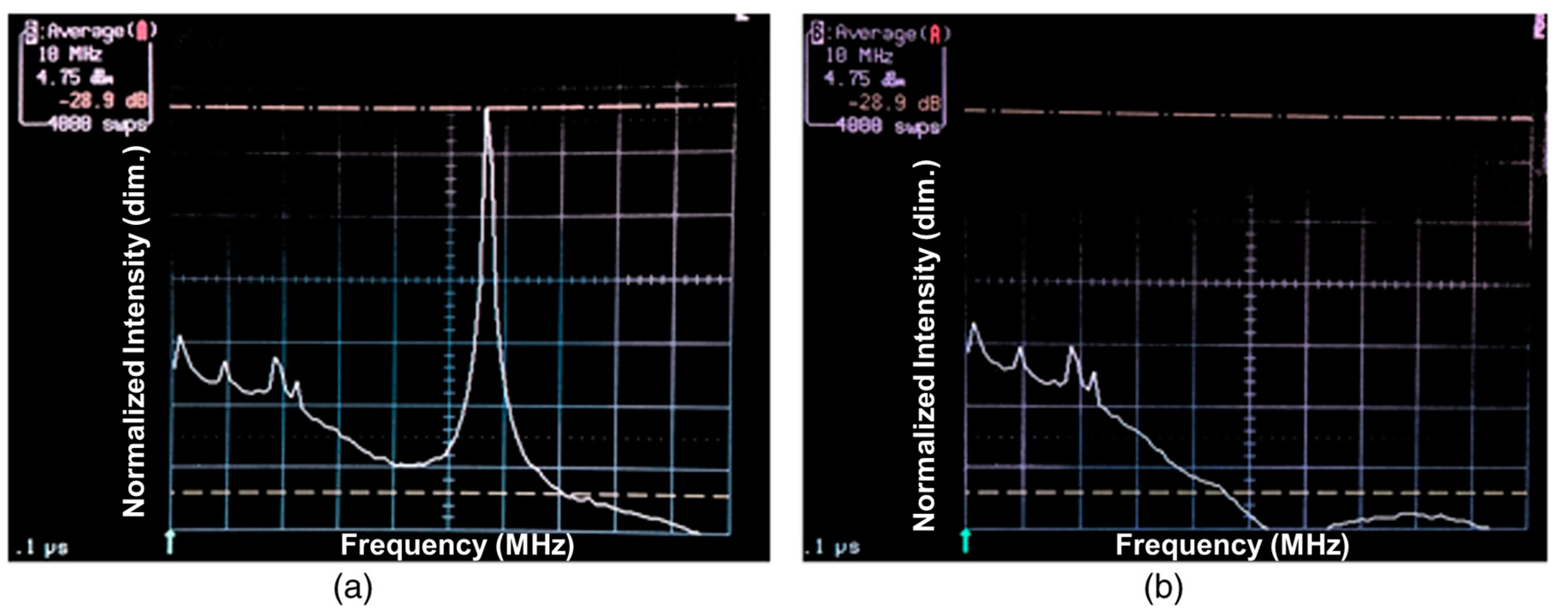
3.2. Steering of Monostatic Coherent Doppler Lidar for Wind Sensing

The use of lidar for atmospheric sensing presents another good fit for the PG steering technology. For example, in coherent 3D wind sensing lidar, a small number of beam directions (typically 2–8) are measured around a fixed cone angle. A coherent Doppler lidar measurement of aerosol backscatter is taken along each line-of-sight (LOS) and angular differences between LOS permit solving for the average 3D wind vector in the sampled volume [59]. The small number of discrete steering angles spaced over a wide angular range is well suited to PG steering, especially for long-range systems requiring larger apertures.
In 2016, a monostatic frequency modulated continuous wave (FMCW) lidar was built to characterize the impact of PG steering on such systems [21]. The FMCW lidar system with PG steerer is schematically illustrated in Figure 12 and described in detail in Serati et al. [21]. Briefly, the system used a 1550 nm single-frequency laser diode, split into a transmit beam and local oscillator. The transmit beam was delivered via COTS fiber optic components to a telescope before passing through a 4-angle PG steering unit with 4-cm clear aperture. Similar to the TOF demonstration above, an additional LC cell was used at the exit aperture of the PG steerer and driven to act as a quarterwave retarder to ensure that light propagated to the target in a linearly polarized state and was returned to a circularly polarized state upon backscatter to the PG steerer.
Upon re-entering the system, the collected backscattered light is separated from the transmitted light by a fiber circulator. This is necessary to split the transmit and receive beams as they are in a common polarization state. The collected light is then mixed with the local oscillator in a 50/50 beam coupler and measured by balanced optical receivers for heterodyne detection.
For this study, we built a 4-angle PG beam steering assembly with 4-cm clear aperture and steering angles of ±1° in azimuth and elevation. The relatively small steering angle was chosen to facilitate indoor measurements. In coherent Doppler lidar of aerosol backscatter, the signal strength of the far-field is sensitive to wavefront error [60], and so this device was fabricated using 3-mm thick glass for the PGs and 2-mm substrates for the LC cells to maintain high wavefront quality. The resulting transmitted wavefront error of the steered beams was measured by a Shack-Hartmann wavefront sensor to vary from λ/61.2 to λ/84.5 RMS at 1550 nm. With the index-matched assembly of three LC cells, two PGs, and anti-reflection coated end caps, the single-pass steering efficiency of the PG steerer was measured to be an average of 89% across the 4 angles, or about 0.5 dB loss.
To determine the impact of the PG steering stages on the lidar, the lidar system was used to measure the Doppler return from a spinning sandpaper disk with and without the PG steerer. The coherent lidar detected the Doppler return from the target and a spectrum analyzer was used to determine the carrier-to-noise ratio (CNR). With the two-stage LCPG beam steerer, four different steer angles were available. The CNR measurements at the four steering angles were 28.9, 29.1, 29.8, and 29.4 dB, which are very close to the 29.7-dB CNR measured without the PG steerer. In this test, the variation due to target reflectivity and estimated 2% measurement error in this experiment was sufficient to mask the effect of insertion loss from the beam steering stack.
In addition to investigating the PG steerer’s impact on CNR, this study sought to evaluate the impact of weak side lobes which could, in theory, create spurious signals when a strong backscatterer is in the path of a side lobe. To quantify this impact, the PG was switched onto (Figure 13a) and then off of (Figure 13b) the spinning disc sandpaper target. When steering off target, the steered beam was directed at a static laboratory environment which generates no Doppler signal. In this state, residual light can remain on target due to imperfect polarization of the transmit beam and/or imperfect polarization control of the LC cells. For this device and system, such residual light was approximately 0.2% of transmitted power. Figure 12 shows a measured ~30 dB decrease in CNR when steering off target, essentially showing no measurable signal from residual light (i.e., side lobes) hitting the target. This is due largely to the opposite polarization state of the residual light relative to the steered beam, which does not efficiently couple back through the PG steerer and cannot generate a coherent signal. This inherent polarization discrimination against stray light is a significant benefit of PG steering in polarization sensitive applications.

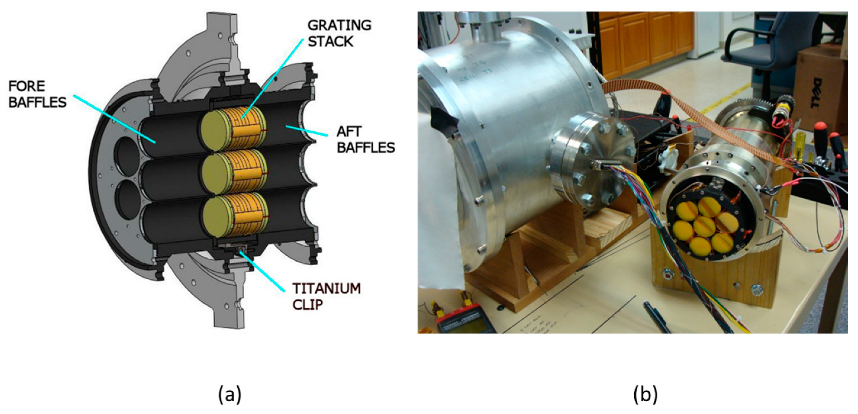
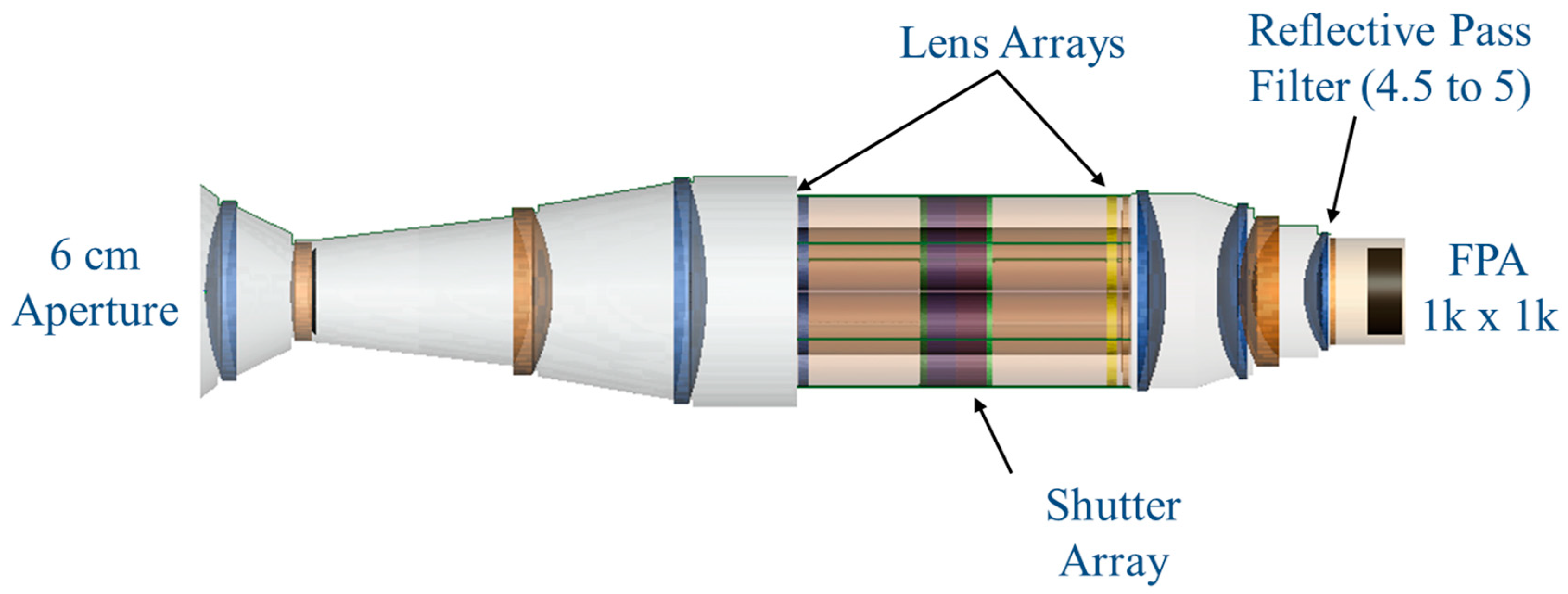
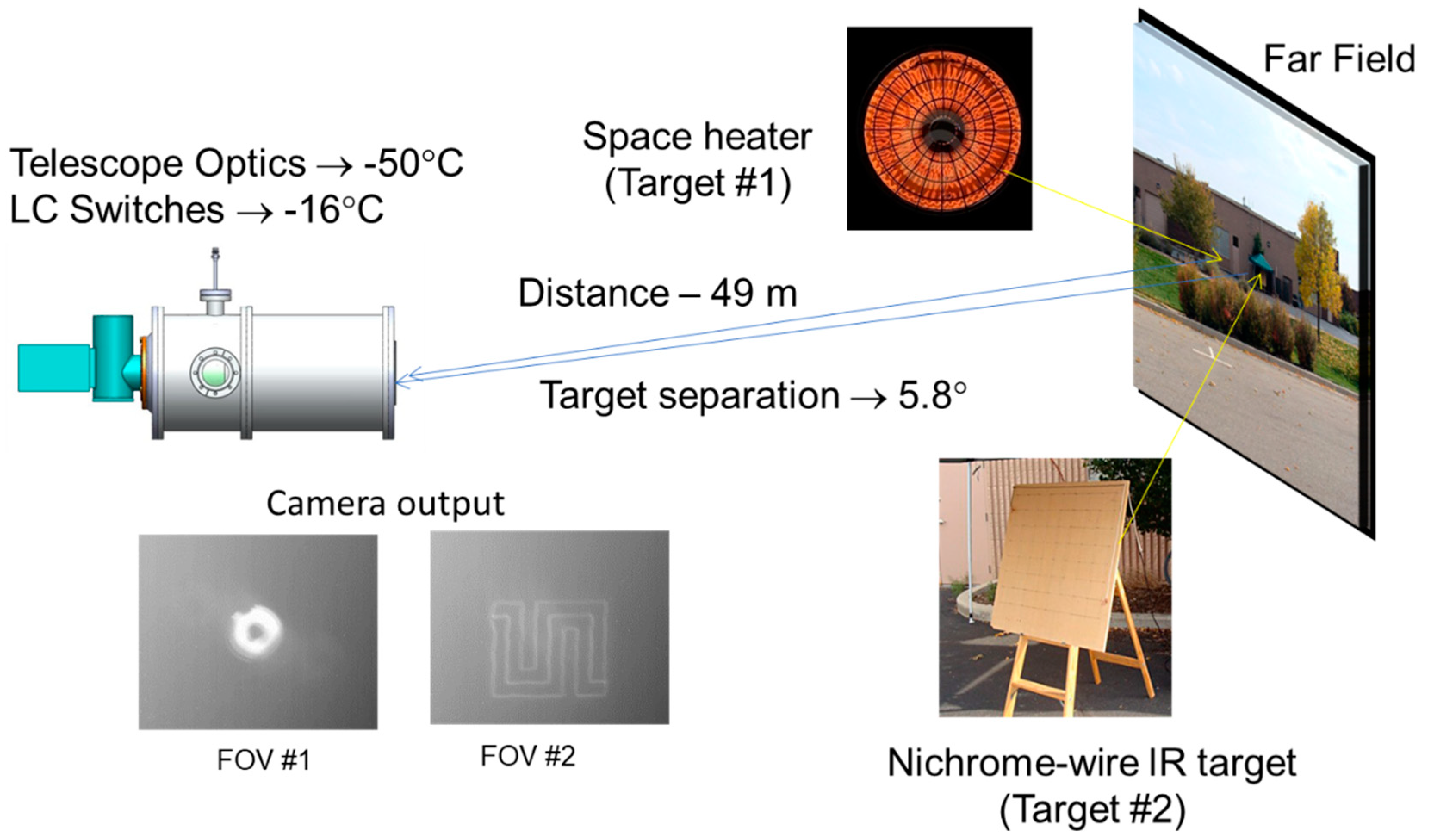
3.3. Broadband Polarization-Insensitive Passive Imaging

In conventional passive imaging systems, the FOV is mechanically scanned over the required field-of-regard (FOR) using large gimbals. For many applications, SWaP of these mechanical beam control systems can be prohibitive. Passive imaging is a challenging application for PG beam steering, where the dispersive and polarization-sensitive nature of PGs normally require filtering out much of the available signal.
To address this challenging application, we developed a compact non-mechanical shutter that uses self-compensating PGs to achieve broadband and polarization-independent operation. When combined with a custom camera lens train, an array of these zone selectors can randomly steer the FOV of a passive imaging system [61]. This technology was demonstrated in the MWIR using a lens array and non-mechanical shutters based on FLC switches and MWIR PGs.
With this non-mechanical shutter array, any portion of the scene could be selected with random access, so there was no slewing (or time) penalty for disparately stepping between widespread FOVs. Despite the long MWIR waveband, the FLC switching was fast with sub-millisecond settling time, and FOV positioning was accurate and consistent (no overshoot, oscillation or hysteresis). These non-mechanical attributes maximize the available integration time of a FOV, while the polarization independence of the approach maximizes the sensitivity of the imaging sensor. The demonstrated system provided advantages over a traditional, inertially constrained, mechanically scanned system, which would need to slew and settle at a new look angle.
The geometry of the non-mechanical shutters consisting of four PGs and two FLC quarter-wave switches combined into a stack is shown in Figure 14 and similar in concept to the visible shutter described in Komanduri et al. [62]. The shutter stack operates as follows: randomly polarized light is incident on a first a grating which in this case splits the light into left hand and right hand circularly polarized components that are deflected at angles of ± αo. A quarter-wave FLC switch pair then will either add together to form a halfwave handedness switch and the light will be deflected another ± αo by the remaining three gratings, or the switches will subtract, resulting in the light being guided back to the zero order and recombined into the randomly polarized state. A spacer is in place between the central grating pair and the final grating to path match the beams so that in the crossed axis (subtraction) state the light recombines in the same plane along the direction of propagation. For the case where the beam is deflected, the light that has been steered out of the field of view of the sensor is not collected. As the effects of the PGs cancel each out in the zero-order transmission state, the device is both polarization-insensitive and dispersion-compensated.
The above shutter concept was used in a MWIR demonstration in which seven shutters (Figure 15) were arranged in an array each of which covered a 5.8° × 5.8° FOV. The light collected by the shutter array was sequentially imaged onto the detector plane and the zones stitched into an effective FOV covering 17.5° × 17.5°.
The shutter array was placed in a telescope assembly consisting of relay optics to image each of the seven zones onto an integrated focal plane array (FPA) as shown in the diagram of Figure 16. The FPA was an InSb infrared camera produced by Santa Barbara Focalplane (ImagIR-SBF184) consisting of 1024 × 1024 pixels, a pixel pitch of 19.5 microns, and a full-frame update rate of 114 Hz.
The imaging system was tested at a range of ~50 m using different targets, including a space heater and nichrome wire that could be temperature controlled by varying the electrical current. Figure 17 shows one of the demonstration experiments. A space heater and a resolution target constructed of nichrome wire were placed in adjacent fields of view and the shutter array switched between the two targets. This particular arrangement provided a good example of the shutter-based imaging system’s ability to block stray light between adjacent zones.

4. Conclusions

When used for non-mechanical beam steering, PGs provide a unique combination of wide angle, large aperture, and manufacturability that makes them attractive for a wide range of optical systems. In this review, we have attempted to summarize the defining characteristics of this steering architecture and highlight several applications that can benefit from PG steering in different ways.
In general, the technology is best suited to narrowband applications that require a modest number of steering angles or in SWaP-constrained applications requiring large clear apertures. Conversely, the technology is often a poor choice to replace conventional raster scanning devices where dense, high-resolution point clouds are to be acquired one angle at a time at high speed. For example, a 512 × 512 resolution image would require an 18-stage PG steering assembly. At an approximate per stage transmission of 96%, such a device would offer a maximum of 48% efficiency and the millisecond-scale switching speeds can push acquisition times into minutes. At this time, these continuous steering applications pose a challenge to PG steering approaches. As previously noted, in these cases PG steering can be paired with small-angle continuous steering modalities, or perhaps with emerging tunable PG approaches [30].
Nevertheless, there is a growing demand for rugged, inexpensive, non-mechanical steering solutions to meet the needs of emerging markets, such as automotive lidar, ground- and satellite-based laser communications, and turbine-mounted wind sensing. In such applications, PG steering has the potential to play a significant role.

Author Contributions

C.H., S.S., and J.S. (Jay Stockley), wrote the manuscript. J.S. (Janelle Shane), K.K., and D.M. revised the manuscript. S.S. led the development of the PG-steered ToF camera and MWIR imager. C.H. led the development of the coherent Doppler lidar work. All authors have read and agreed to the published version of the manuscript.

Funding

Section 3.1 was supported under NASA Phase I SBIR contract 80NSSC18P2206. Section 3.2 was supported under NASA Phase I SBIR contract NNX15CL44P. Section 3.3 was supported under Air Force Phase II SBIR contract FA8650-08-C-1311.

Institutional Review Board Statement

Not applicable.

Informed Consent Statement

Not applicable.

Data Availability Statement

No new data were created or analyzed in this study. Data sharing is not applicable to this article.

Acknowledgments

The authors gratefully acknowledge Lance Hosting and Nicole Soledad for assistance in component fabrication, Hugh Masterson for assistance in optical design, Roylnn Serati for mechanical design, and Sammy Henderson and Charley Hale for assistance with coherent Doppler lidar measurements.

Conflicts of Interest

Boulder Nonlinear Systems, Inc. is a for-profit company specializing in liquid crystal technologies, including PG beam steering.

References

  1. McManamon Paul, F.; Bos Philip, J.; Escuti Michael, J.; Heikenfeld, J.; Serati, S.; Xie, H.; Watson Edward, A. A Review of Phased Array Steering for Narrow-Band Electrooptical Systems. Proc. IEEE 2009, 97, 1078–1096. [Google Scholar] [CrossRef]
  2. McManamon, P.F.; Ataei, A. Progress and opportunities in the development of nonmechanical beam steering for electro-optical systems. Opt. Eng. 2019, 58, 120901. [Google Scholar] [CrossRef]
  3. Smith, I.W.; Holz, M.K.O. Wide-Angle Beam Steering System. U.S. Patent 7,215,472, 8 May 2007. [Google Scholar]
  4. Chen, P.; Jin, Y.; He, D.; Chen, J.; Xu, J.; Zhao, J.; Zhang, Y.; Kong, F.; He, H.; Shao, J. Design and fabrication of multiplexed volume Bragg gratings as angle amplifiers in high power beam scanning system. Opt. Express 2018, 26, 25336–25346. [Google Scholar] [CrossRef] [PubMed]
  5. He, Z.; Gou, F.; Chen, R.; Yin, K.; Zhan, T.; Wu, S.-T. Liquid Crystal Beam Steering Devices: Principles, Recent Advances, and Future Developments. Crystals 2019, 9, 292. [Google Scholar] [CrossRef] [Green Version]
  6. Wang, X.; Wilson, D.; Muller, R.; Maker, P.; Psaltis, D. Liquid-crystal blazed-grating beam deflector. Appl. Opt. 2000, 39, 6545–6555. [Google Scholar] [CrossRef] [PubMed] [Green Version]
  7. Gori, F. Measuring Stokes parameters by means of a polarization grating. Opt. Lett. 1999, 24, 584–586. [Google Scholar] [CrossRef]
  8. Bomzon, Z.; Biener, G.; Kleiner, V.; Hasman, E. Space-variant Pancharatnam–Berry phase optical elements with computer-generated subwavelength gratings. Opt. Lett. 2002, 27, 1141–1143. [Google Scholar] [CrossRef]
  9. Escuti, M.J.; Jones, W.M. 39.4: Polarization-Independent Switching with High Contrast from a Liquid Crystal Polarization Grating. SID Symp. Dig. Tech. Pap. 2006, 37, 1443–1446. [Google Scholar] [CrossRef]
  10. Kim, J.; Oh, C.; Escuti, M.J.; Hosting, L.; Serati, S. Wide-angle nonmechanical beam steering using thin liquid crystal polarization gratings. In Advanced Wavefront Control: Methods, Devices, and Applications VI; International Society for Optics and Photonics: lingham, WA, USA, 2008; Volume 7093, pp. 709302–709312. [Google Scholar] [CrossRef]
  11. Nersisyan, S.R.; Tabiryan, N.V.; Steeves, D.M.; Kimball, B.R. The principles of laser beam control with polarization gratings introduced as diffractive waveplates. In Liquid Crystals XIV; International Society for Optics and Photonics: Bellingham, WA, USA, 2010; Volume 7775, p. 77750U. [Google Scholar] [CrossRef]
  12. Kim, J.; Oh, C.; Serati, S.; Escuti, M.J. Wide-angle, nonmechanical beam steering with high throughput utilizing polarization gratings. Appl. Opt. 2011, 50, 2636–2639. [Google Scholar] [CrossRef]
  13. Kim, J.; Miskiewicz, M.N.; Serati, S.; Escuti, M.J. Nonmechanical Laser Beam Steering Based on Polymer Polarization Gratings: Design Optimization and Demonstration. J. Lightwave Technol. 2015, 33, 2068–2077. [Google Scholar] [CrossRef]
  14. Oh, C.; Escuti, M.J. Numerical analysis of polarization gratings using the finite-difference time-domain method. Phys. Rev. A 2007, 76, 043815. [Google Scholar] [CrossRef] [Green Version]
  15. Divliansky, I. Volume Bragg Gratings: Fundamentals and Applications in Laser Beam Combining and Beam Phase Transformations. Hologr. Mater. Opt. Syst. 2017. [Google Scholar] [CrossRef] [Green Version]
  16. Oh, C.; Escuti, M.J. Time-domain analysis of periodic anisotropic media at oblique incidence: An efficient FDTD implementation. Opt. Express 2006, 14, 11870–11884. [Google Scholar] [CrossRef]
  17. Chen, H.; Weng, Y.; Xu, D.; Tabiryan, N.V.; Wu, S.-T. Beam steering for virtual/augmented reality displays with a cycloidal diffractive waveplate. Opt. Express 2016, 24, 7287–7298. [Google Scholar] [CrossRef] [PubMed] [Green Version]
  18. Weng, Y.; Xu, D.; Zhang, Y.; Li, X.; Wu, S.-T. Polarization volume grating with high efficiency and large diffraction angle. Opt. Express 2016, 24, 17746–17759. [Google Scholar] [CrossRef] [PubMed]
  19. Xiang, X.; Kim, J.; Escuti, M.J. Bragg polarization gratings for wide angular bandwidth and high efficiency at steep deflection angles. Sci. Rep. 2018, 8. [Google Scholar] [CrossRef] [Green Version]
  20. Gao, K.; McGinty, C.; Payson, H.; Berry, S.; Vornehm, J.; Finnemeyer, V.; Roberts, B.; Bos, P. High-efficiency large-angle Pancharatnam phase deflector based on dual-twist design. Opt. Express 2017, 25, 6283–6293. [Google Scholar] [CrossRef]
  21. Serati, S.; Hoy, C.L.; Hosting, L.; Kluttz, K.; Stockley, J.; Hale, C. Large-aperture, wide-angle nonmechanical beam steering using polarization gratings. Opt. Eng. 2016, 56, 031211. [Google Scholar] [CrossRef]
  22. Sarkissian, H.; Serak, S.V.; Tabiryan, N.V.; Glebov, L.B.; Rotar, V.; Zeldovich, B.Y. Polarization-controlled switching between diffraction orders in transverse-periodically aligned nematic liquid crystals. Opt. Lett. 2006, 31, 2248–2250. [Google Scholar] [CrossRef]
  23. Cheng, H.-H.; Bhowmik, A.; Bos, P.J. 51.2: Large Angle Image Steering Using a Liquid Crystal Device. SID Symp. Dig. Tech. Pap. 2014, 45, 739–742. [Google Scholar] [CrossRef]
  24. Escuti, M.J.; Kim, J.; Oh, C.; Serati, S. Beam Steering Devices Including Stacked Liquid Crystal Polarization Gratings and Related Methods of Operation. U.S. Patent 8,982,313 B2, 17 March 2015. [Google Scholar]
  25. Crawford, G.P.; Eakin, J.N.; Radcliffe, M.D.; Callan-Jones, A.; Pelcovits, R.A. Liquid-crystal diffraction gratings using polarization holography alignment techniques. J. Appl. Phys. 2005, 98, 123102. [Google Scholar] [CrossRef] [Green Version]
  26. Nersisyan, S.R.; Tabiryan, N.V.; Steeves, D.M.; Kimball, B.R. Characterization of optically imprinted polarization gratings. Appl. Opt. 2009, 48, 4062–4067. [Google Scholar] [CrossRef] [PubMed]
  27. Miskiewicz, M.N.; Escuti, M.J. Direct-writing of complex liquid crystal patterns. Opt. Express 2014, 22, 12691–12706. [Google Scholar] [CrossRef]
  28. Davis, S.R.; Rommel, S.D.; Johnson, S.; Anderson, M.H.; Yu, A.W. Liquid crystal clad waveguide laser scanner and waveguide amplifier for LADAR and sensing applications. In Integrated Optics: Devices, Materials, and Technologies XIX; International Society for Optics and Photonics: Bellingham, WA, USA, 2015; Volume 9365, p. 93650N. [Google Scholar] [CrossRef]
  29. Shi, L.; McManamon, P.F.; Bos, P.J. Liquid crystal optical phase plate with a variable in-plane gradient. J. Appl. Phys. 2008, 104, 033109. [Google Scholar] [CrossRef] [Green Version]
  30. Yousefzadeh, C.; van Rynbach, A.; Bryant, D.; Bos, P. High-efficiency, tunable, fringe-field switching-mode beam steering based on a liquid crystal Pancharatnam phase. Appl Opt. 2020, 59, 10706–10718. [Google Scholar] [CrossRef] [PubMed]
  31. Yin, K.; Lee, Y.-H.; He, Z.; Wu, S.-T. Stretchable, flexible, rollable, and adherable polarization volume grating film. Opt. Express 2019, 27, 5814–5823. [Google Scholar] [CrossRef] [PubMed]
  32. Provenzano, C.; Pagliusi, P.; Cipparrone, G. Highly efficient liquid crystal based diffraction grating induced by polarization holograms at the aligning surfaces. Appl. Phys. Lett. 2006, 89, 121105. [Google Scholar] [CrossRef]
  33. Nieborek, M.; Rutkowska, K.; Woliński, T.R.; Bartosewicz, B.; Jankiewicz, B.; Szmigiel, D.; Kozanecka-Szmigiel, A. Tunable Polarization Gratings Based on Nematic Liquid Crystal Mixtures Photoaligned with Azo Polymer-Coated Substrates. Crystals 2020, 10, 768. [Google Scholar] [CrossRef]
  34. Lu, J.; Deshpande, S.; Gulari, E.; Kanicki, J.; Warren, W. Ultraviolet light induced changes in polyimide liquid-crystal alignment films. J. Appl. Phys. 1996, 80. [Google Scholar] [CrossRef] [Green Version]
  35. Lin, P.-T.; Wu, S.-T.; Chang, C.-Y.; Hsu, C.-S. UV Stability of High Birefirngence Liquid Crystals. Mol. Cryst. Liquid Cryst. 2004, 411, 243–253. [Google Scholar] [CrossRef]
  36. Deangelis, A.; Rougier, A.; Manaud, J.-P.; Labrugère, C.; Miller, E.; Gaillard, N. Temperature-resistant high-infrared transmittance indium molybdenum oxide thin films as an intermediate window layer for multi-junction photovoltaics. Solar Energy Mater. Solar Cells 2014, 127, 174–178. [Google Scholar] [CrossRef]
  37. Wu, S.-T. Infrared properties of nematic liquid crystals: An overview. Opt. Eng. 1987, 26, 120–128. [Google Scholar] [CrossRef]
  38. Peng, F.; Lee, Y.H.; Chen, H.; Li, Z.; Bostwick, A.E.; Twieg, R.J.; Wu, S.T. Low absorption chlorinated liquid crystals for infrared applications. Opt. Mater. Express 2015, 5, 1281–1288. [Google Scholar] [CrossRef]
  39. Gou, F.; Peng, F.; Ru, Q.; Lee, Y.H.; Chen, H.; He, Z.; Zhan, T.; Vodopyanov, K.L.; Wu, S.T. Mid-wave infrared beam steering based on high-efficiency liquid crystal diffractive waveplates. Opt. Express 2017, 25, 22404–22410. [Google Scholar] [CrossRef]
  40. Oh, C.; Escuti, M.J. Achromatic diffraction from polarization gratings with high efficiency. Opt. Lett. 2008, 33, 2287–2289. [Google Scholar] [CrossRef] [PubMed]
  41. Miroslaw, O.; Harford, S.; Doughty, N.; Hoffman, C.; Sanchez, M.; Gutow, D.; Pierce, R. Risley prism beam pointer. In Free-Space Laser Communications VI; International Society for Optics and Photonics: Bellingham, WA, USA, 2006; Volume 6304, p. 630406. [Google Scholar] [CrossRef]
  42. Skolnik, M.I. Introduction to Radar Systems; McGraw-Hill: New York, NY, USA, 1962. [Google Scholar]
  43. Dąbrowski, R.; Dziaduszek, J.; Ziółek, A. Low viscosity, high birefringence liquid crystalline compounds and mixtures. Opto-Electron. Rev. 2007, 15, 47–51. [Google Scholar] [CrossRef]
  44. Gauza, S.; Zhu, X.; Piecek, W.; Dabrowski, R.; Wu, S. Fast Switching Liquid Crystals for Color-Sequential LCDs. J. Display Technol. 2007, 3, 250–252. [Google Scholar] [CrossRef]
  45. Wu, S.; Wu, C. High-speed liquid-crystal modulators using transient nematic effect. J. Appl. Phys. 1989, 65, 527–532. [Google Scholar] [CrossRef]
  46. Bos, P.J.; Koehler, K.R. The pi-Cell: A Fast Liquid-Crystal Optical-Switching Device. Mol. Cryst. Liquid Cryst. 1984, 113, 329–339. [Google Scholar] [CrossRef]
  47. Escuti, M.J.; Bowley, C.C.; Crawford, G.P.; Žumer, S. Enhanced dynamic response of the in-plane switching liquid crystal display mode through polymer stabilization. Appl. Phys. Lett. 1999, 75, 3264–3266. [Google Scholar] [CrossRef]
  48. Fan, Y.-H.; Lin, Y.-H.; Ren, H.; Gauza, S.; Wu, S.-T. Fast-response and scattering-free polymer network liquid crystals for infrared light modulators. Appl. Phys. Lett. 2004, 84, 1233–1235. [Google Scholar] [CrossRef]
  49. Wu, Y.H.; Lin, Y.H.; Lu, Y.Q.; Ren, H.; Fan, Y.H.; Wu, J.R.; Wu, S.T. Submillisecond response variable optical attenuator based on sheared polymer network liquid crystal. Opt. Express 2004, 12, 6382–6389. [Google Scholar] [CrossRef] [Green Version]
  50. Love, G.D.; Bhandari, R. Optical properties of a QHQ ferroelectric liquid crystal phase modulator. Opt. Commun. 1994, 110, 475–478. [Google Scholar] [CrossRef]
  51. Guo, Q.; Xu, L.; Sun, J.; Yang, X.; Liu, H.; Yan, K.; Zhao, H.; Chigrinov, V.G.; Kwok, H.S. Fast switching beam steering based on ferroelectric liquid crystal phase shutter and polarisation grating. Liquid Cryst. 2019, 46, 1383–1388. [Google Scholar] [CrossRef]
  52. Lapanik, V.; Bezborodov, V.; Timofeev, S.; Haase, W. Shock-free ferroelectric liquid crystal displays with high optical contrast. Appl. Phys. Lett. 2010, 97, 251913. [Google Scholar] [CrossRef]
  53. Komanduri, R.K.; Lawler, K.F.; Escuti, M.J. A high throughput liquid crystal light shutter for unpolarized light using polymer polarization gratings. In Acquisition, Tracking, Pointing, and Laser Systems Technologies XXV; International Society for Optics and Photonics: Bellingham, WA, USA, 2011; Volume 8052, p. 80520R. [Google Scholar] [CrossRef]
  54. DeBoo, B.J.; Sasian, J.M.; Chipman, R.A. Depolarization of diffusely reflecting man-made objects. Appl. Opt. 2005, 44, 5434–5445. [Google Scholar] [CrossRef] [PubMed]
  55. Tan, S.; Stoker, J. Multiwavelength Polarimetric Lidar for Foliage Obscured Man-Made Target Detection. Adv. Geosci. Remote Sens. 2009. [Google Scholar] [CrossRef] [Green Version]
  56. Stabo-Eeg, F.; Letalick, D.; Steinvall, O.; Lindgren, M. Discriminating land mines from natural backgrounds by depolarization. In Electro.-Optical Remote Sensing, Photonic Technologies, and Applications II; International Society for Optics and Photonics: Bellingham, WA, USA, 2008; Volume 7114, p. 71140H. [Google Scholar] [CrossRef]
  57. Yan, L.; Wu, T.; Wang, X. Polarization Remote Sensing for Land Observation. In Understanding of Atmospheric Systems with Efficient Numerical Methods for Observation and Prediction; IntechOpen: London, UK, 2018. [Google Scholar] [CrossRef] [Green Version]
  58. McManamon, P.F.; Banks, P.; Beck, J.; Fried, D.G.; Huntington, A.S.; Watson, E.A. Comparison of flash lidar detector options. Opt. Eng. 2017, 56, 031223. [Google Scholar] [CrossRef] [Green Version]
  59. Hill, C. Coherent Focused Lidars for Doppler Sensing of Aerosols and Wind. Remote Sens. 2018, 10, 466. [Google Scholar] [CrossRef] [Green Version]
  60. Rye, B.J. Primary aberration contribution to incoherent backscatter heterodyne lidar returns. Appl Opt. 1982, 21, 839–844. [Google Scholar] [CrossRef]
  61. Masterson, H.; Serati, R.; Serati, S.; Buck, J. MWIR wide-area step and stare imager. In Acquisition, Tracking, Pointing, and Laser Systems Technologies XXV; International Society for Optics and Photonics: Bellingham, WA, USA, 2011; Volume 8052, p. 80520N. [Google Scholar] [CrossRef]
  62. Komanduri, R.K.; Lawler, K.F.; Escuti, M.J. Multi-twist retarders: Broadband retardation control using self-aligning reactive liquid crystal layers. Opt. Express 2013, 21, 404–420. [Google Scholar] [CrossRef] [PubMed] [Green Version]
Figure 1. Schematic representations of a PG showing (a) in-plane director rotation and pitch and (b) orientation of steering.
Crystals 11 00361 g001
Figure 2. Spectral and angular bandwidth of PGs. (a) The impact of incident angle on PG diffraction efficiency for PGs with diffraction angles of ±3°, ±6°, and ±12° and 1550 nm design wavelength. (b) Spectrum of the zero-order light transmitted through a PG designed for 1550 nm as a function of wavelength. The minimum represents the wavelength of peak diffraction.
Crystals 11 00361 g002
Figure 3. Efficiency of an example PG beam steering (a) single stage and (b) 5-stage device. In (a), a 30-mm clear aperture nematic ECB cell is mated to a PG steering 1550 nm light to ± 3.5°. In (b), a 50-mm clear aperture beam steering assembly was built to steer 905 nm light over ± 37° in approximately 3° steps.
Crystals 11 00361 g003
Figure 4. Measured wavefront error for (a) a 10 cm clear aperture PG and a (b) 10 cm clear aperture nematic LC variable retarder, both designed for 1550 nm operation. Measurements taken by Shack-Hartmann wavefront sensor at (a) 532 nm and (b) 633 nm test wavelengths and scaled to 1550 nm design wavelength.
Crystals 11 00361 g004
Figure 5. Foreshortening of beam waist during beam steering from a fixed planar aperture. As with Risley prisms and phased arrays, non-mechanical beam steering with PGs leads to a progressive foreshortening of the beam waist along the direction of steering.
Crystals 11 00361 g005
Figure 6. Sub-millisecond switching of a nematic ECB cell acting as a handedness switch for 915 nm light. This oscilloscope screen capture was taken while using the ECB cell to control handedness of light incident on a PG, thereby steering 915 nm light onto and off of a photodetector. The trace depicts phtoddetector output voltage as a finction of time. For clarity, the amplitude and timebase have been enlarged and reproduced in the upper right inset. Each vertical division of the screen is 500 mV and each horizontal division is 1 ms.
Crystals 11 00361 g006
Figure 7. Polarization dynamics during monostatic PG beam steering. (a) Due to the handedness flip experienced by circularly polarized light during backscattering, the returning light is in an opposite handedness state and steers off-path during return (b) A quarter wave can be used to transmit and receive light in a constant linearly polarized state, enabling retracing of the transmit path upon backscatter.
Crystals 11 00361 g007
Figure 8. High-resolution, wide-angle TOF camera and schematic showing optical modifications to COTS camera.
Crystals 11 00361 g008
Figure 9. First and second steps in converting a COTS QVGA TOF camera into a high-resolution 3D imager. Targets are approximately 2 m from the native and NFOV TOF cameras.
Crystals 11 00361 g009
Figure 10. Wide-angle, high-resolution image and point cloud generated using LCPG scanning combined with narrow-FOV TOF image tiling. The test scene is between 1.9–2.3 m from the camera.
Crystals 11 00361 g010
Figure 11. Two dimensional developed for next generation wide-angle, high-resolution TOF camera. Further size reduction is possible by building the LC components on thinner substrates.
Crystals 11 00361 g011
Figure 12. Schematic representation of the coherent lidar breadboard used to evaluate PG beam steering contributions to phase noise and insertion loss in a Doppler detection application. Modified from Serati et al.
Crystals 11 00361 g012
Figure 13. CNR measurements through the two-axis beam steering stack. (a) Representative Doppler return with steered beam on target. (b) Measured Doppler signal with beam steered off of target, showing contribution of any leakage beam to signal. No contribution is detectable.
Crystals 11 00361 g013
Figure 14. Geometry of the LCPG-based polarization independent shutter. (a) The optic axes of the two FLC quarter-wave switches are parallel and they add to form a half-wave which changes the handedness of the light resulting in continued beam divergence; (b) If the optic axes of the quarter-wave switches are crossed, the polarization does not change handedness and the light returns to the zero order and remains in the field of view of the sensor.
Crystals 11 00361 g014
Figure 15. Details of the seven-shutter array. (a) The PG shutter assemblies were placed in a Hex-7 pattern in a baffled housing; (b) The shutter array housing was cooled to liquid nitrogen temperatures to mitigate thermal noise.
Crystals 11 00361 g015
Figure 16. Diagram of the telescope assembly incorporating the shutter array and relay optics integrated with the InSb infrared FPA.
Crystals 11 00361 g016
Figure 17. Imaging tests with hot targets at a range of ~50 m. The testing verified the effective shutter extinction of hot, bright targets. The targets were separated by 5.8° to verify the switching of the field-of-regard.
Crystals 11 00361 g017
Publisher’s Note: MDPI stays neutral with regard to jurisdictional claims in published maps and institutional affiliations.

