Article

In-Situ Formed Al3Zr Compounds Reinforced Al Composites and Tribological Application

1
Joining and Welding Research Institute, Osaka University, Ibaraki, Osaka 5670047, Japan
2
Department of Mechanical Engineering, Osaka University, Suita, Osaka 5670047, Japan
3
School of Materials Science and Engineering, Xi’an University of Technology, Xi’an 710048, China
*
Author to whom correspondence should be addressed.
Crystals 2021, 11(3), 227; https://doi.org/10.3390/cryst11030227
Submission received: 11 February 2021 / Revised: 19 February 2021 / Accepted: 22 February 2021 / Published: 25 February 2021
(This article belongs to the Special Issue Crystalline Microstructures in Stainless Steels)

Abstract

:
An Al3Zr-reinforced Al matrix composite using metal powders was fabricated via in-situ synthesis in vacuum; these were subjected to a pin-on-disc wear test with a SUS304 disc specimen under oil lubrication. The elemental mixture of Al and ZrH2 particles was sintered in vacuum for the in-situ-formed Al3Zr. ZrH2 particles were thermally decomposed in the reaction with the Al matrix to form hard Al3Zr intermetallic compounds. The friction coefficient and wear volume values of the Al–Al3Zr composites were significantly lower than those of the pure Al specimen. This is attributed to the uniform dispersion of Al3Zr particles in the Al matrix, which prevented the metallurgical bond from falling and blocked the direct contact between the Al matrix and SUS304 disc.

1. Introduction

Aluminum has been proven as an important advanced material for structural and vehicular applications [1,2] due to its high strength-to-weight ratio, excellent formability, corrosion resistance, and electrical and thermal conductivities. However, compared with steel materials, Al materials have some disadvantages owing to their low hardness and poor friction and wear properties; in addition, they are more active, because of which seizure is more likely to occur. There are two common methods for improving the wear characteristics of Al matrix composites: surface modification using surface hard-coating [3,4,5] and strengthening the aluminium matrix substrate [6,7,8]. The former includes cold spraying [9] using diamond-like carbon coatings [10], alumite processing [11], shot peening processing [12], and plasma electrolytic oxidation [3,13]. This process helps improve friction and wear characteristics by forming a hard layer on the surface of the Al matrix composite, thereby creating a protective layer. The wear resistance is strongly dependent on both the mechanical properties of the hard layer and the bonding coherence between the hard layer and Al matrix. The latter process involves adding hard ceramic particles to the aluminum matrix substrate, such as Al2O3 [14,15], Si [16,17], SiC [18,19,20], B4C [20,21], TiB2 [22,23], and TiC [24,25]. Using a conventional premixing process, these ceramic particles form reinforcements in the aluminium matrix composites. The chemical reactions between the added elements and the base metal form reinforcements in the metal matrix. However, these hard particles are only mechanically bonded in the metal matrix, which causes them to detach from the matrix under severe sliding conditions, thereby leading to abrasive wear and increase in wear debris [26]. The hard particles of the wear debris between the sliding surfaces are intercepted as abrasive particles. These particles induce abrasive wear not only in the aluminium matrix material but also in the counterpart material [16]. Using an in-situ synthesis process, strong interfaces formed between the reinforcement particles and matrix material. Vivekananda clarified that the bonding of TiB2 particles greatly contributes to the improvement of the friction and wear characteristics of the Al matrix [27]. Among the in-situ-formed particulate-reinforced aluminium matrix composites that have been developed in recent decades, only a few have been thoroughly researched, such as Al–Al3Zr composites. Varin explained that Al3Zr is in thermodynamic equilibrium with the aluminium matrix, which means that there is a real chemical bond between Al and the intermetallic particle rather than an intermediate reaction zone [28]. However, the minimal data is available on composites reinforced with in-situ-formed Al3Zr intermetallic particles using the powder metallurgy process. This study evaluated the matrix-strengthening process that incorporates the in-situ Al3Zr synthesis in vacuum to improve the tribological properties of pure aluminium matrix materials for commercial applications as wear resistant materials in structural and vehicular applications. As starting materials, an elemental mixture of pure Al powder and zirconium hydride (ZrH2) particles was used to form Al3Zr in the aluminium matrix material via solid-state reaction in vacuum condition. A wear test was conducted on the Al–Al3Zr composite material using oil lubrication to investigate the effects of Al3Zr particles.

2. Materials and Methods

2.1. Materials Fabrication

Commercially pure Al powders (Kojundo Chemical Laboratory Co., Sakado, Japan, 99.9%) with a mean particle size of 17 μm, shown in Figure 1a, and ZrH2 powders (Mitsuwa Chemical Co., Ltd., Osaka, Japan, 97.8%) with a maximum powder size of ~40 μm, shown in Figure 1(b-1,b-2), were used as raw materials in this study. To add Zr, dehydrogenation was carried out via thermal decomposition reaction using ZrH2 particles. In this process, the electrostatic discharge sensitivity [29] was lower than that of pure Zr powder. The pre-mixed powders used contained 0, 5, and 10 wt% ZrH2 particles, respectively. These were prepared in plastic bottles (500 mL) filled with argon gas and sealed. Each corresponding bottle containing the material was labelled as pure Al, Al–5 wt% ZrH2, and Al–10 wt% ZrH2, respectively. The powders were treated using a 10.8 ks table-top ball mill (AV-2, Asahi Rika Seisakusho, Chiba, Japan) at a speed of 90 rpm. The ball-to-powder ratio was approximately 1:5, using zirconia balls with a diameter of 1.0 mm. The mixed powders were sintered by a spark plasma sintering system (SPS), (SPS-1030S, SPS Syntech Co., Kawasaki, Japan) at 893 K for 10.8 ks with a maximum pressure of 15 MPa under a vacuum atmosphere (6 Pa). The vacuum condition is necessary for the solid-state sintering of Al powders due to preventing the oxidation of powder surfaces. Thereafter, the sintered billets were heat treated at 913 K for 10.8 ks in a vacuum atmosphere (100 Pa) to promote the solid solution of Zr atoms into an Al matrix using a vacuum furnace (FT-1200 R-250, Full-tech Co., Yao, Japan). In this case, the vacuum atmosphere, not argon gas atmosphere is also useful to accelerate the diffusion of Zr elements by controlling oxidation phenomenon. Then, forging to consolidate for applied to densify the heated billets using a 2000 kN hydraulic direct press machine (SHP-200-450, Shibayamakikai Co., Tsubame, Japan). They were forged at 873 K with a ram speed of 6 mm/s, maximum load of 800 kN, heating speed of 2 K/s, and holding time of 1.8 ks. The relative density of the Al–5 wt% and –10 wt% ZrH2 composites increased from 85% to 96%, respectively. The compactness of the Al–ZrH2-forged sample was lower than those of Al-forged samples due to the in-situ-formed Al3Zr hard particles in the matrix. However, the effect of pores on the frictional behaviour was negligible. Thereafter, the specimens used for microstructural observations and wear testing were obtained by hot forging. The wear test specimens with length of 15 mm and diameter of 5 mm, with a spherical finish, were machined from the forged materials.

2.2. Materials Characterization

O, N, and H contents of milled powders and forged samples were measured using an O/N/H element analyser (EMGA-830, HORIBA, Kyoto, Japan). The milled powder and forged samples were examined using X-ray diffraction (XRD-6100, Shimadzu Co., Kyoto, Japan) with Cu-Kα radiation (λ = 1.54 Å) and a sampling pitch of 0.02° and scan speed of 0.2°/min. The hardness of the materials was measured by Vickers micro-hardness tester (HMV-G, Shimadzu Co., Japan) with 0.025 N applied at 293 K, and the average Vickers Pyramid Number (HV) of 20 measurements was used as the representative value of the specimens. The intermetallic formation of Al3Zr specimens and microstructures of wear tracks were characterised using an optical microscope and scanning electron microscope (FE-SEM) (JSM-7100F, JEOL Ltd., Akishima, Japan) equipped with energy-dispersive spectroscopy (EDS) (JED-2300, JEOL Ltd., Japan). The intermetallic formation of Al–ZrH2 composites were characterized by a locally selected area by transmission electron microscopy (TEM, JEM-2010, JEOL).

2.3. Wear Test

The tribological behaviour of the samples was investigated using a pin-on-disc wear test (FPR-2100, RHESCA Co., Ltd., Hino, Japan) in lubricated conditions (SAE30, Mobile) at 293 K. A stainless steel 304 (SUS304) disc were used as the counter specimen. A surface roughness of SUS304 disk and each pin specimen is Ra 0.8, respectively. The test was conducted with a rotation speed of 200 mm/s, track radius of 10 mm, wear test time of 10.8 ks, and applied loads of 2.9 and 4.9 N. The wear test condition was determined by referring the condition reported in our previous works [7,30]. The frictional torque between the pin and SUS304 disc specimens during the wear test was automatically recorded, and a friction coefficient was calculated from the measurement. The average friction coefficient value was measured from three specimens for each with pin-on-disc wear test and was used as a representative value of each pin specimens. After the sliding wear test, the damaged sliding surface of the pin was investigated using FE-SEM with EDS to determine the effect of the Zr atoms solution into the Al material on the wear phenomena. The wear sliding surface of the disc was investigated using a digital microscope (DSX), (DSX500, Olympus Co., Tokyo, Japan). The surface roughness of the SUS304 disc specimen after wear test was measured using a profile meter (Surfcom1400D, Tokyo Seimitsu, Hachioji, Japan) and the average wear track value of four measurements was used as the representative value of the specimens.

3. Results

3.1. Materials Characterisation

The representative microstructures and XRD results of pure Al, Al–5 wt% ZrH2, and Al–10 wt% ZrH2 forged materials used in the wear test are shown in Figure 2. No coarse pores were observed in any of the forged materials (Figure 2a–c). The in-situ-fabricated Al3Zr particles uniformly exist on the Al matrix and no agglomeration of additive ZrH2 particles was observed in the Al–5 wt% ZrH2 (Figure 2b) and Al–10 wt% ZrH2 (Figure 2c) forged materials. The XRD profiles (Figure 2d) display ZrH2 powder and forged materials using pure Al, Al–5 wt% ZrH2, and Al–10 wt% ZrH2. No ZrH2 diffraction peak (△) was detected in the forged materials and an Al3Zr diffraction peak (■) was detected in Al–5 wt% ZrH2 and Al–10 wt% ZrH2 forged materials. This indicates that the additive ZrH2 particles were completely decomposed and that the Zr atoms reacted with the Al matrix. According to the results of the H element analysis, there was no significant increase in the H contents of each material, in which the values of pure Al, Al–5 wt% ZrH2, and Al–10 wt% ZrH2 forged materials are 0.004%, compared with the values of each of the mixed powders (0.015, 0.115, and 0.205 wt%, respectively). H2 atoms originated from ZrH2 particles were evaporated by SPS and heat treatment. Figure 3 demonstrates the SEM-EDS mapping and line-scan analysis results of the Al–10 wt% ZrH2 forged materials, corresponding to the in-situ-formed Al3Zr intermetallic compound particle. The line-scan analysis (Figure 3b) clearly detected a ratio of approximately 3:1, that is, 75 wt% Al and 25 wt% Zr. The mapping results of the particle (Figure 3c,d) demonstrate the presence of Al-poor and Zr-rich areas that originated from the ZrH2 particles. The average size of Al3Zr particle in the Al matrix was 9.16 μm. Figure 4 is the TEM image and the diffraction pattern of Al–10 wt% ZrH2 forged material used in the wear test. Figure 4a shows TEM observation a Al3Zr particle in the Al matrix, agreeing with the XRD observations (Figure 2d). It can be seen that the interface between the Al matrix and Al3Zr particle phase is no voids and inclusions, resultant Al3Zr was metallurgically bonded to the Al matrix by in-situ formation with the Al matrix and ZrH2 particles. The Al and Al3Zr phases were identified by the SAED patterns, as shown in Figure 4b,c. A crystal relation between Al3Zr and Al is found to be Al3Zr [101]//Al [200].
The Vickers micro-hardness results for the pure Al, Al–10 wt% ZrH2 forged materials, Al3Zr intermetallic compound, and SUS304 disc are shown in Table 1. The Vickers micro-hardness of the Al3Zr of the Al–10 wt% ZrH2 forged materials (545 HV) is significantly higher than those of the Al matrix (35 HV), pure Al (33 HV), and SUS304 disc (291 HV). Additionally, to obtain a more accurate measurement of the hardness of Al3Zr, an Al3Zr single-phase alloy was prepared using the sintering process. First, ZrH2 particles were mixed with 26 wt% Zr in Al powder. The mixed powder was sintered by SPS at 873 K and 30 MPa for 3.6 ks. It was then subjected to vacuum heat treatment at 1273 K for 3.6 ks and again sintered at 1373 K and 30 MPa for 10.8 ks. The existence of Al3Zr and Al2Zr was confirmed using XRD analysis; the main phase was found to be Al3Zr. The micro-hardness for Al3Zr in the Al3Zr alloy was 645 HV, which is higher than in the Al-10 wt% ZrH2 forged material (545 HV). The reason for this difference is the soft Al matrix in the alloy with a sufficient size and depth, compared with that in the Al3Zr compound in the alloy. In summary, with regard to the in-situ-formed Al3Zr compounds, the added ZrH2 particles are thermally decomposed and the dissociated Zr atoms reacted with the surrounding Al atoms to form a hard Al3Zr intermetallic compound at 873 K. The above results are in good agreement with the findings of previous studies [31,32].

3.2. Friction and Wear Behaviour

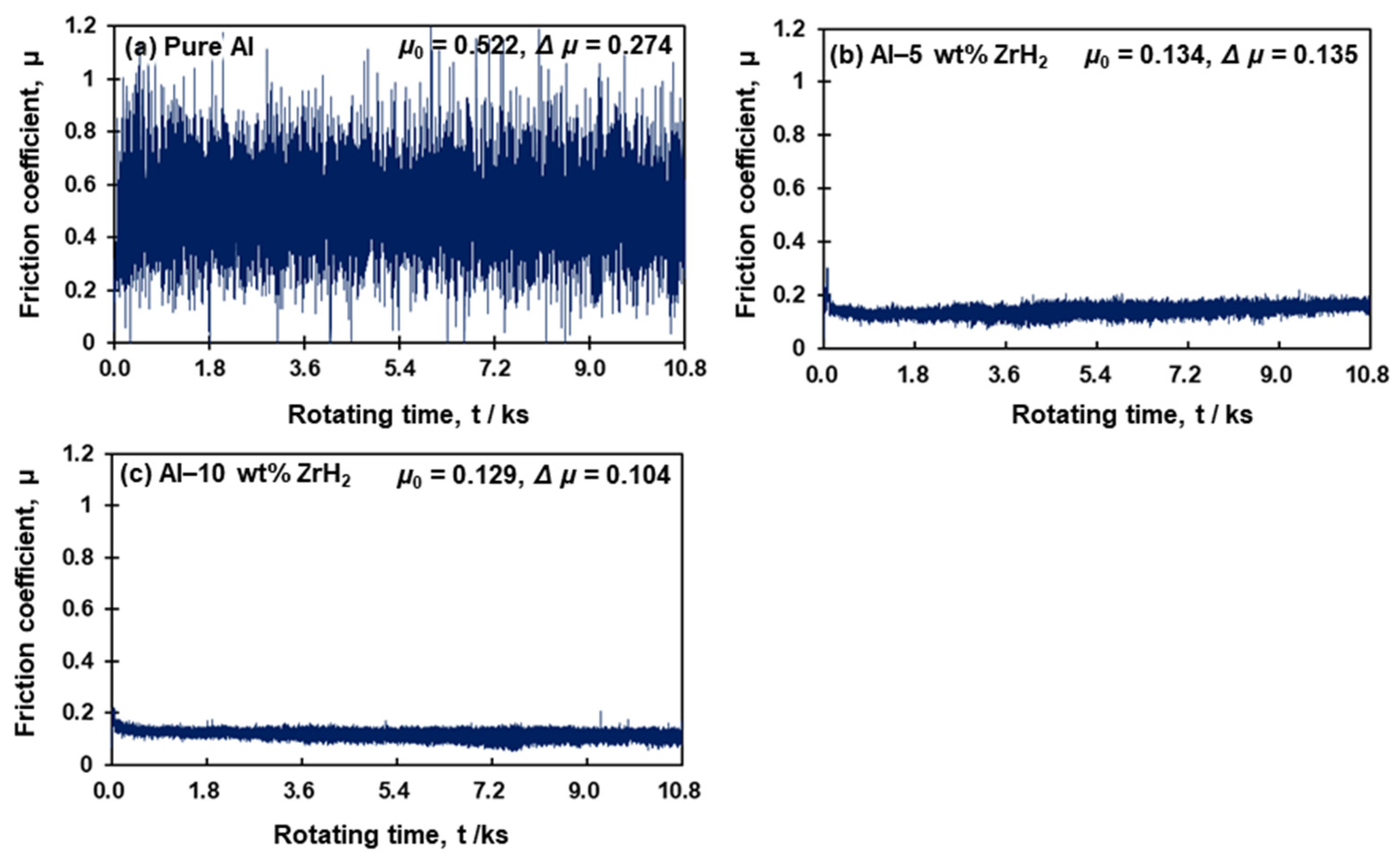
The friction coefficient changes in the pin specimen of (a) pure Al, (b) Al–5 wt% ZrH2, and (c) Al–10 wt% ZrH2 using the pin-on-disc wear test under an applied load of 4.9 N with lubricated condition are shown in Figure 5. The Al–ZrH2 composite specimens, as shown in Figure 5b,c exhibit a lower and more stable change in the friction coefficient compared with pure Al material, as shown in Figure 5a. The friction coefficient changed significantly in the profile of Figure 5a pure Al. The mean friction coefficient (μ0) and mean variation (Δμ) of pure Al were 0.522 and 0.274, respectively. The profile and values of (a) pure Al clearly indicate the stick-slip phenomenon in the adhesive wear occurring at the soft pure Al pin surfaces sticking to the hard SUS304 disc specimens during sliding. In contrast, the profiles of Figure 5b Al–5 wt% ZrH2 and Figure 5c Al–10 wt% ZrH2 displayed a stable sliding behaviour in the initial period, with a significantly low friction coefficient. Al–5 wt% ZrH2 displayed μ0 and Δμ values of 0.134 and 0.135, respectively, with the corresponding values of 0.129 and 0.104 for Al–10 wt% ZrH2, respectively. These values were smaller than those of pure Al. When a load of 2.9 N was applied, the ZrH2-added composite material exhibited a low and stable friction coefficient change compared with the pure Al specimen.
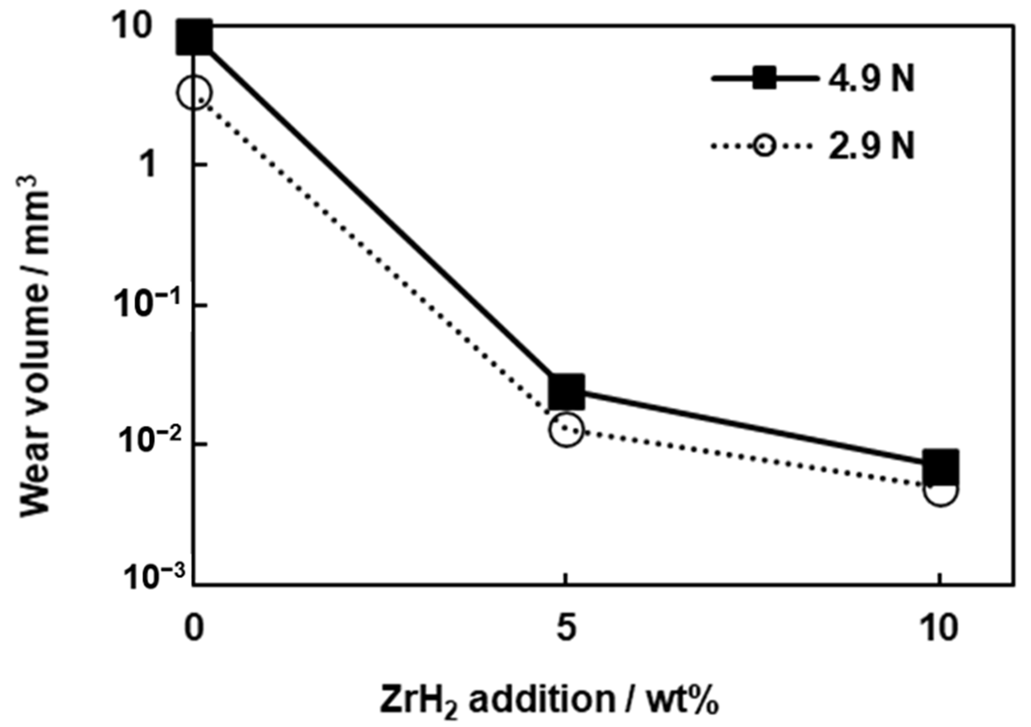
Figure 6 shows that the dependence of the friction coefficient change averaged over thrice under applied loads of 2.9 and 4.9 N. The values of μ0 and Δμ are observed to decrease with increasing ZrH2 content. For example, for Al–10 wt% ZrH2, μ0 and Δμ had values of 0.128 and 0.145 at 2.9 N, and 0.129 and 0.104 at 4.9 N, respectively, while pure Al had μ0 and Δμ values of 0.420 and 0.417 at 2.9 N, and 0.520 and 0.263 at 4.9 N, respectively. This indicates that the in-situ-formed Al3Zr in Al specimens effectively reduced the friction torque at the sliding surface of the SUS304 disc. To investigate the amount of wear loss to the pin specimens after the wear test, the radius of the sliding surface of each pin specimen was measured using DSX and the subsequent wear volume was calculated. The results of the wear volume for loads of 2.9 and 4.9 N are shown in Figure 7. It was confirmed that the amount of wear volume was reduced significantly in the Al3Zr-dispersed Al composite material compared with the pure Al specimen under different load conditions. In addition, regardless of the amount of ZrH2 particles, the amount of wear decreased due to the decreasing applied load. It is considered that the dispersion of the in-situ-formed hard Al3Zr particles significantly improved the wear resistance of the Al material and reduced the wear volume. These results are in good agreement with the in-situ-formed strengthening effect values of the Al3Zr particles in the Al matrix composite [27,30].
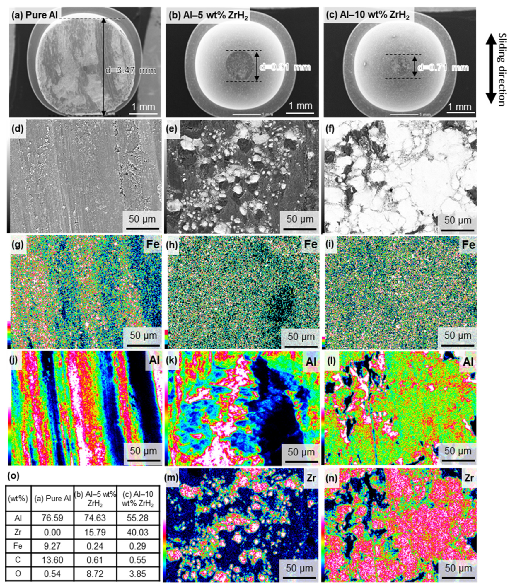
To clarify the wear behaviour of each specimen, sliding surface observation on the pin specimens and SUS304 discs was conducted using SEM-EDS analysis. The surface morphology observation results of the wear damages of each pin specimen are summarised in Figure 8. Figure 8a display the case of pure Al specimens of 3.47 µm diameter with a lot of debris and severe wear damages in contact with the SUS304 disc observed on the sliding surface. The results (Figure 8g,j) of the EDS mapping analysis in Figure 8d reveals that the Fe elements (9.27 wt%) originated from the SUS304 disc. This is due to the severe abrasive wear phenomenon that occurred due to the micro-hardness of the SUS304 disc (291 HV). This is significantly larger than that of the pure Al pin (33 HV). In contrast, as displayed in Figure 8b Al–5 wt% ZrH2 and Figure 8c Al–10 wt% ZrH2 pin specimens revealed 0.91 µm and 0.71 µm diameter, respectively, with small amount of wear debris. In the EDS mapping analysis results (Figure 8h,i,k–n) of the sliding surface of Figure 8e Al–5 wt% ZrH2 and Figure 8f Al–10 wt% ZrH2 pin specimens, only a slight adhesion of Fe (Figure 8h,i) was detected for 0.24 and 0.29 wt% specimens and no adhesion phenomenon were observed over the sliding surface. It also showed that the Al3Zr particles did not fall off the spots where these particles were metallurgically bonded to the Al matrix. It revealed a smooth and stable sliding condition formed at the contacting interface between the disc and pin specimens by the Al3Zr particles.
The detailed SEM-EDS analysis results at the wear tracks of each SUS304 disc are displayed in Figure 9 for the pin specimens of Al–10 wt% ZrH2 and pure Al. In the case of the SUS304 disc using Al–10 wt% ZrH2 pin specimen (Figure 9a), the area where Al was observed was limited with a small adhesion area of Al (Figure 9c). In contrast, in the case of SUS304 disc using pure Al pin specimen (Figure 9b), it was confirmed that Al (Figure 9d) adhered to the entire area of the sliding component and were detected in 21.94 wt%, compared with 3.52 wt% in those of Al–10 wt% ZrH2 specimen. In addition, SUS304 disc using pure Al pin specimen (Figure 9(b-1)) displayed the obvious adhesion of Al on the SUS304 disc (Figure 9e). From the SEM-EDS analysis, a large amount of Fe, which is the main component of the SUS304 disc, was found in correspondence with the Al3Zr compound specimen. In other words, the hard Al3Zr particles were mainly responsible for the contact with the SUS304 disc, which prevented the direct contact between the Al matrix and disc. This result is in good agreement with the decrease in Δμ value due to the addition of ZrH2 particles shown in Figure 6 and the adhesion phenomenon of Al on the SUS304 disc suppressed by the dispersion effect of the hard Al3Zr particles in Al matrix. It also suggested that the slip phenomenon was less likely to occur.
Figure 10 shows the surface roughness profiles of the wear track on the SUS304 disc. When the pure Al pin specimen was used (Figure 10a), the surface roughness at the sliding area was severe. Compared with the non-sliding part, a maximum recess of ap proximately 8 µm was measured, which indicates the damage caused by adhesive wear [26,30]. For the surface roughness of SUS304 disc using Al–5 wt% ZrH2 (Figure 10b) and Al–10 wt% ZrH2 (Figure 10c), no significant differences were observed in the surface properties from the start to the end of the measurement points. It was difficult to clearly distinguish the sliding and non-sliding parts; therefore, the wear of the disc material hardly occurred.
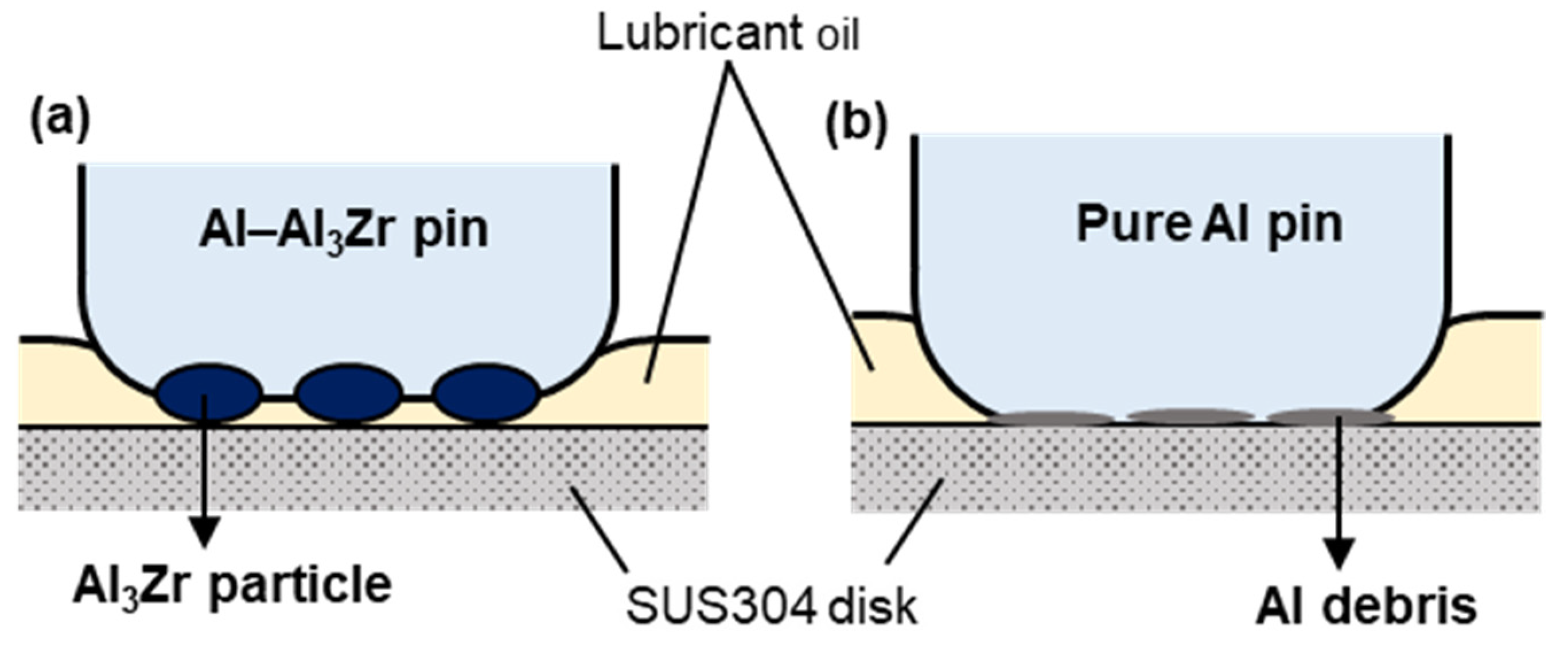
In summary, in this study, the frictional wear mechanism of hard Al3Zr particles dispersed in the Al matrix composite and pure Al pin specimens in the SUS304 disc were considered. Based on the schematic illustration in Figure 11a depicting the Al–Al3Zr pin specimen, the Al matrix (35 HV), which has a lower hardness than the Al3Zr particles (545 HV), was first worn out and Al3Zr particles protruded during the sliding wear. These protrusions of the hard Al3Zr particles were mainly responsible for the direct contact with the SUS304 disc. Moreover, it was clarified that the lubricating oil remained between the Al3Zr particles and the oil film pressure generated prevented the direct contact between the Al matrix and the SUS304 disc. As a consequence, the friction coefficient showed a lower and more stable proportion of pure Al composite material containing Al3Zr hard particles, which reduced its wear volume and that of SUS304 disc. As described above, it is considered that the protrusion phenomenon of Al3Zr hard particles occurred as a similar phenomenon to that in a previous Al-Si study [33]. It was reported the protrusion acting as a roller bearing at the interface and indicated that the high concentration of hard particles was responsible for reducing the frictional coefficient of the Al matrix interfacing with the counter material. Thus, the tribological properties of in-situ-fabricated Al–Al3Zr composite material have been significantly improved. Conversely, as shown in the pure Al pin (Figure 11b), the active new surface is formed on the Al surface by sliding while SUS304 disc and pure Al pin specimen are in strong contact at the initial stage, thereby causing a severe adhesive wear phenomenon. In addition, as the oil film on the sliding surface is reduced, it is considered that the progress of the adhesive wear between the pure Al pin and SUS304 disc caused the formation of a pit on the sliding surface as shown in Figure 10a.

4. Conclusions

To improve the tribological properties of Al matrix materials, Al3Zr dispersion-reinforced Al composites were prepared by in-situ synthesis. The formation mechanism of Al3Zr intermetallic compound was clarified. ZrH2 particles were thermally decomposed in a pure Al matrix and the dissociated Zr atoms reacted with the surrounding Al atoms to form a hard Al3Zr intermetallic compound via in-situ synthesis. The friction coefficient and wear volume values of the Al–Al3Zr composites were significantly lower than those of the pure Al specimen. The average value of the friction coefficient was 0.12~0.14 of the Al–Al3Zr composites, in contrast a value of the pure Al specimen was 0.42~0.52. The average value of the wear volume was drastically decreased from 8.56 mm3 of the pure Al specimen to 0.024 of the Al–10 wt% ZrH2 specimen and 0.007 of the Al–10 wt% ZrH2 specimen. SEM–EDS analysis clarified that Al3Zr particles were not detached from the Al matrix after wear test due to its strong bonding via in-situ formation of Al3Zr formation via solid-state reaction. The frictional behaviour of Al–Al3Zr composites is attributed to the uniform dispersion of Al3Zr particles in the Al matrix, which prevented the metallurgical bond from falling and blocked the direct contact between the Al matrix and SUS304 disc.

Author Contributions

J.U.: Conceptualization, Investigation, Writing—original draft, Writing—review & editing, Visualization. N.N.: Methodology, Investigation, Visualization. H.F.: Investigation, Visualization. L.J.: Methodology. K.K.: Methodology, Supervision, Funding acquisition. All authors have read and agreed to the published version of the manuscript.

Funding

This research was funded by the Project to Create Research and Educational Hubs for Innovative Manufacturing in Asia, Osaka University of the Special Budget Project of the Ministry of Education, Culture, Sports, Science and Technology.

Informed Consent Statement

Not applicable.

Data Availability Statement

The data presented in this study are available on request from the corresponding author.

Acknowledgments

This study was financially supported by the Project to Create Research and Educational Hubs for Innovative Manufacturing in Asia, Osaka University of the Special Budget Project of the Ministry of Education, Culture, Sports, Science and Technology.

Conflicts of Interest

The authors declare no conflict of interest.

References

  1. Starke, E.A.; Staley, J.T. Application of modern aluminium alloys to aircraft. In Fundamentals of Aluminium Metallurgy: Production, Processing and Applications; Lumley, R., Ed.; Woodhead Publishing: Cambridge, UK, 2010; pp. 747–783. [Google Scholar]
  2. Hirsch, J. Recent development in aluminium for automotive applications. Trans. Nonferrous Met. Soc. China (Engl. Ed.) 2014, 24, 1995–2002. [Google Scholar] [CrossRef]
  3. Huang, X.; Famiyeh, L. Plasma Electrolytic Oxidation Coatings on Aluminium Alloys: Microstructures, Properties, and Applications. Mod. Concepts Mater. Sci. 2019, 2, 000526. [Google Scholar]
  4. Chu, H.; Lin, J. Experimental analysis of the tribological behavior of electroless nickel-coated graphite particles in aluminium matrix composites under reciprocating motion. Wear 2000, 239, 126–142. [Google Scholar] [CrossRef]
  5. Li, N.; Zhang, L.; Xu, M.; Xia, T.; Ruan, X.; Song, S.; Ma, H. Preparation and mechanical property of electrodeposited Al-graphene composite coating. Mater. Des. 2016, 111, 522–527. [Google Scholar] [CrossRef]
  6. Tabandeh-Khorshid, M.; Omrani, E.; Menezes, P.; Rohatgi, P. Tribological performance of self-lubricating aluminum matrix nanocomposites: Role of graphene nanoplatelets. Eng. Sci. Technol. Int. J. 2016, 19, 463–469. [Google Scholar] [CrossRef] [Green Version]
  7. Kondoh, K.; Umeda, J.; Watanabe, R. Cavitation resistance of powder metallurgy aluminum matrix composite with AlN dispersoids. Mater. Sci. Eng. A 2009, 499, 440–444. [Google Scholar] [CrossRef]
  8. Chen, B.; Shen, J.; Ye, X.; Imai, H.; Umeda, J.; Takahashi, M.; Kondoh, K. Solid-state interfacial reaction and load transfer efficiency in carbon nanotubes (CNTs)-reinforced aluminium matrix composites. Carbon 2017, 114, 198–208. [Google Scholar] [CrossRef]
  9. Bakshi, S.; Singh, V.; Balani, K.; McCartney, D.; Seal, S.; Agarwal, A. Carbon nanotube reinforced aluminium composite coating via cold spraying. Surf. Coat. Technol. 2008, 202, 5162–5169. [Google Scholar] [CrossRef]
  10. Wang, L.; Wan, S.; Wang, S.C.; Wood, R.J.K.; Xue, Q.J. Gradient DLC-based nanocomposite coatings as a solution to improve tribological performance of aluminium alloy. Tribol. Lett. 2010, 38, 155–160. [Google Scholar] [CrossRef] [Green Version]
  11. Ishikawa, Y.; Matsumoto, Y. Electrodeposition of TiO2 photocatalyst into nano-pores of hard alumite. Electrochim. Acta 2001, 46, 2819–2824. [Google Scholar] [CrossRef]
  12. Noordhuis, J.; Hosson, J. Surface modification by means of laser melting combined with shot peening: A novel approach. Acta Metall. Mater. 1992, 40, 3317–3324. [Google Scholar] [CrossRef] [Green Version]
  13. Wu, X.; Qin, W.; Guo, Y.; Xie, Z. Self-lubricative coating grown by micro-plasma oxidation on aluminium alloys in the solution of aluminate-graphite. Appl. Surf. Sci. 2008, 254, 6395–6399. [Google Scholar] [CrossRef]
  14. Chen, B.; Kondoh, K.; Umeda, J.; Li, S.; Jia, L.; Li, J. Interfacial in-situ Al2O3 nanoparticles enhance load transfer in carbon nanotube (CNT)-reinforced aluminium matrix composites. J. Alloys Compd. 2019, 789, 25–29. [Google Scholar] [CrossRef]
  15. Hossein-Zadeh, M.; Mirzaee, O.; Saidi, P. Structural and mechanical characterization of Al-based composite reinforced with heat treated Al2O3 particles. Mater. Des. 2014, 54, 245–250. [Google Scholar] [CrossRef]
  16. Dey, S.K.; Perry, T.A.; Alpas, A.T. Micromechanisms of low load wear in an Al-18.5% Si alloy. Wear 2009, 267, 515–524. [Google Scholar] [CrossRef]
  17. Kori, S.A.; Chandrashekharaiah, T.M. Studies on the dry sliding wear behaviour of hypoeutectic and eutectic Al-Si alloys. Wear 2007, 263, 745–755. [Google Scholar] [CrossRef]
  18. Mousavia, R.T.; Khosroshahi, R.A.; Yazdani, S.; Brabazon, D.; Boostani, A.F. Fabrication of aluminum matrix composites reinforced with nano- to micrometer-sized SiC particles. Mater. Des. 2016, 89, 58–70. [Google Scholar] [CrossRef] [Green Version]
  19. Ghasali, E.; Pakseresht, A.; Rahbari, A.; Eslami-Shahed, H.; Alizadeh, M.; Ebadzadeh, T. Mechanical properties and microstructure characterization of spark plasma and conventional sintering of Al-SiC-TiC composites. J. Alloys Compd. 2016, 666, 366–371. [Google Scholar] [CrossRef]
  20. Shorowordi, K.M.; Haseeb, A.; Celis, J.P. Tribo-surface characteristics of Al-B4C and Al-SiC composites worn under different contact pressures. Wear 2006, 261, 634–641. [Google Scholar] [CrossRef]
  21. Harichandran, R.; Selvakumar, N. Effect of nano/micro B4C particles on the mechanical properties of aluminium metal matrix composites fabricated by ultrasonic cavitation-assisted solidification process. Arch. Civ. Mech. Eng. 2016, 16, 147–158. [Google Scholar] [CrossRef]
  22. Vivekananda, A.S.; Prabu, S.B. Wear Behaviour of In Situ Al/TiB2 Composite: Influence of the Microstructural Instability. Tribol. Lett. 2018, 66, 1–14. [Google Scholar] [CrossRef]
  23. Krishnamurthy, K.; Venkatesh, J. Assessment of Surface Roughness and Material Removal Rate on Machining of TIB2 Reinforced Aluminium 6063. Composites: A Taguchi’s Approach. Int. J. Sci. Res. 2013, 3, 1–6. [Google Scholar]
  24. Popov, V.A.; Shelekhov, E.V.; Prosviryakov, A.S.; Presniakov, M.Y.; Senatulin, B.R.; Kotov, A.D.; Khomutov, M.G. Particulate metal matrix composites development on the basis of in situ synthesis of TiC reinforcing nanoparticles during mechanical alloying. J. Alloys Compd. 2017, 707, 365–370. [Google Scholar] [CrossRef]
  25. Baskaran, S.; Anandakrishnan, B.; Duraiselvam, M. Investigations on dry sliding wear behavior of in situ casted AA7075-TiC metal matrix composites by using Taguchi technique. Mater. Des. 2014, 60, 184–192. [Google Scholar] [CrossRef]
  26. Landolt, D.; Mischler, S.; Stemp, M.; Barril, S. Third body effects and material fluxes in tribocorrosion systems involving a sliding contact. Wear 2004, 256, 517–524. [Google Scholar] [CrossRef]
  27. Vivekananda, A.S.; Balasivanandha, P.S.; Paskaramoorthy, R. Combined effect of process parameters during aluminothermic reaction process on the microstructure and mechanical properties of in situ Al/TiB2 composite. J. Alloys Compd. 2018, 735, 619–634. [Google Scholar] [CrossRef]
  28. Varin, R.V. Intermetallic-reinforced light-metal matrix in-situ composites. Metall. Mater. Trans. A Phys. Metall. Mater. Sci. 2002, 33, 193–201. [Google Scholar] [CrossRef]
  29. Dufaud, O.; Bideau, D.; Guyadec, F.; Corriou, J.P.; Perrin, L.; Caleyron, A. Self ignition of layers of metal powder mixtures. Powder Technol. 2014, 254, 160–169. [Google Scholar] [CrossRef]
  30. Kondoh, K.; Takeda, Y. Tribological property of in situ directly nitrided and sintered Al/AlN composite. Powder Metall. 2000, 43, 69–75. [Google Scholar] [CrossRef]
  31. Laik, A.; Bhanumurthy, K.; Kale, G.B. Intermetallics in the Zr-Al diffusion zone. Intermetallics 2004, 12, 69–74. [Google Scholar] [CrossRef]
  32. Okamoto, H. Al-Zr (aluminum-zirconium). J. Phase Equilibria 1993, 14, 259–260. [Google Scholar] [CrossRef]
  33. Kumar, P.; Wani, M.F. Tribological Characterisation of Hypereutectic Al-25Si Alloy under Dry and Lubricated Sliding Conditions. J. Tribol. 2018, 140, 1–19. [Google Scholar] [CrossRef]
Figure 1. SEM observation images of (a) pure Al powder and (b) ZrH2 particles as raw powders used in this study.
Crystals 11 00227 g001
Figure 2. SEM observation images of (a) pure Al, (b) Al–5 wt% ZrH2 and (c) Al–10 wt% ZrH2 forged material used in wear test and their (d) XRD results.
Crystals 11 00227 g002
Figure 3. SEM–EDS analysis of Al–10 wt% ZrH2 forged material used in the wear test. (a) SEM image, (b) corresponding EDS line scan, and (c,d) Al and Zr elements distri-bution maps in (a).
Crystals 11 00227 g003
Figure 4. TEM analysis of Al–10 wt% ZrH2 forged material used in the wear test. (a) TEM image, (b) SAED pattern of Al matrix in (a), and (c) SAED pattern of Al3Zr particle in (a).
Crystals 11 00227 g004
Figure 5. Changes in the friction coefficient of SUS304 disc under an applied load of 4.9 N using (a) pure Al, (b) Al–5 wt% ZrH2, and (c) Al–10 wt% ZrH2 pin specimens.
Crystals 11 00227 g005
Figure 6. Changes in the friction coefficient averaged over three measurements for pure Al, –5, and –10 wt% ZrH2 under applied loads of 2.9 and 4.9 N. The table lists the mean friction coefficient (μ0) and its mean variation (Δμ), and their standard deviation for each pin specimens under applied loads of 2.9 and 4.9 N.
Crystals 11 00227 g006
Figure 7. Wear volume averaged thrice for pure Al, –5, and –10 wt% ZrH2 pin specimen under applied loads of 2.9 and 4.9 N.
Crystals 11 00227 g007
Figure 8. SEM–EDS analysis on the wear surface of (a) pure Al, (b) Al–5 wt% ZrH2, and (c) Al–10 wt% ZrH2 pin specimen under an applied load of 4.9 N. (df) High magnification images of (ac). (gn) The corresponding Fe, Al, and Zr elements distribution maps in (gi). (o) The quantitative EDS analysis results of (ac).
Crystals 11 00227 g008
Figure 9. SEM–EDS analysis on the wear track of the SUS304 disc under an applied load of 4.9 N using (a) Al–10 wt% ZrH2, (b) pure Al pin specimen, and (b-1) high magnification image of (b). (ch) The corresponding Al and Zr elements distribution maps in (a,b,b-1). (i) The quantitative EDS analysis results of (a) and (b).
Crystals 11 00227 g009
Figure 10. Surface roughness profiles of the wear track of SUS304 disk under an applied load of 4.9 N using (a) pure Al, (b) Al–5 wt% ZrH2, and (c) Al–10 wt% ZrH2 pin specimens.
Crystals 11 00227 g010
Figure 11. Schematic illustration of the wear mechanisms of the (a) Al–Al3Zr composite and (b) pure Al pin used in the SUS304 disc as the counter material.
Crystals 11 00227 g011
Table 1. Vickers micro-hardness values of pure Al, Al–Al3Zr composite, Al3Zr IMC, and SUS304 disc.
MaterialsPure AlAl-Al3ZrAl3Zr IMC *SUS304 Disk
Al3ZrAl Matrix
Micro-hardness (HV)3354535645291
* Intermetallic compound.
Publisher’s Note: MDPI stays neutral with regard to jurisdictional claims in published maps and institutional affiliations.