Article

Effect of Deformation on Topological Properties of Cobalt Monosilicide

by
Sergey Nikolaev
,
Dmitry Pshenay-Severin
*,†,
Yuri Ivanov
and
Alexander Burkov
Ioffe Institute, 26 Politekhnicheskaya, 194021 St Petersburg, Russia
*
Author to whom correspondence should be addressed.
These authors contributed equally to this work.
Crystals 2021, 11(2), 143; https://doi.org/10.3390/cryst11020143
Submission received: 30 December 2020 / Revised: 25 January 2021 / Accepted: 26 January 2021 / Published: 29 January 2021
(This article belongs to the Special Issue Advances in Topological Materials)

Abstract

:
Recently, it was shown that materials with certain crystal structures can exhibit multifold band crossings with large topological charges. CoSi is one such material that belongs to non-centrosymmetric space group P2 1 3 (#198) and posseses multifold band crossing points with a topological charge of 4. The change of crystal symmetry, e.g., by means of external stress, can lift the degeneracy and change its topological properties. In the present work, the influence of uniaxial deformation on the band structure and topological properties of CoSi is investigated on the base of ab initio calculations. The k · p Hamiltonian taking into account deformation is constructed on the base of symmetry consideration near the Γ and R points both with and without spin-orbit coupling. The transformation of multifold band crossings into nodes of other types with different topological charges, their shift both in energy and in reciprocal space and the tilt of dispersion around nodes are studied in detail depending on the direction of uniaxial deformation.

Graphical Abstract

1. Introduction

Cobalt monosilicide crystallizes in the cubic noncentrosymmetric space group #198 (P2 1 
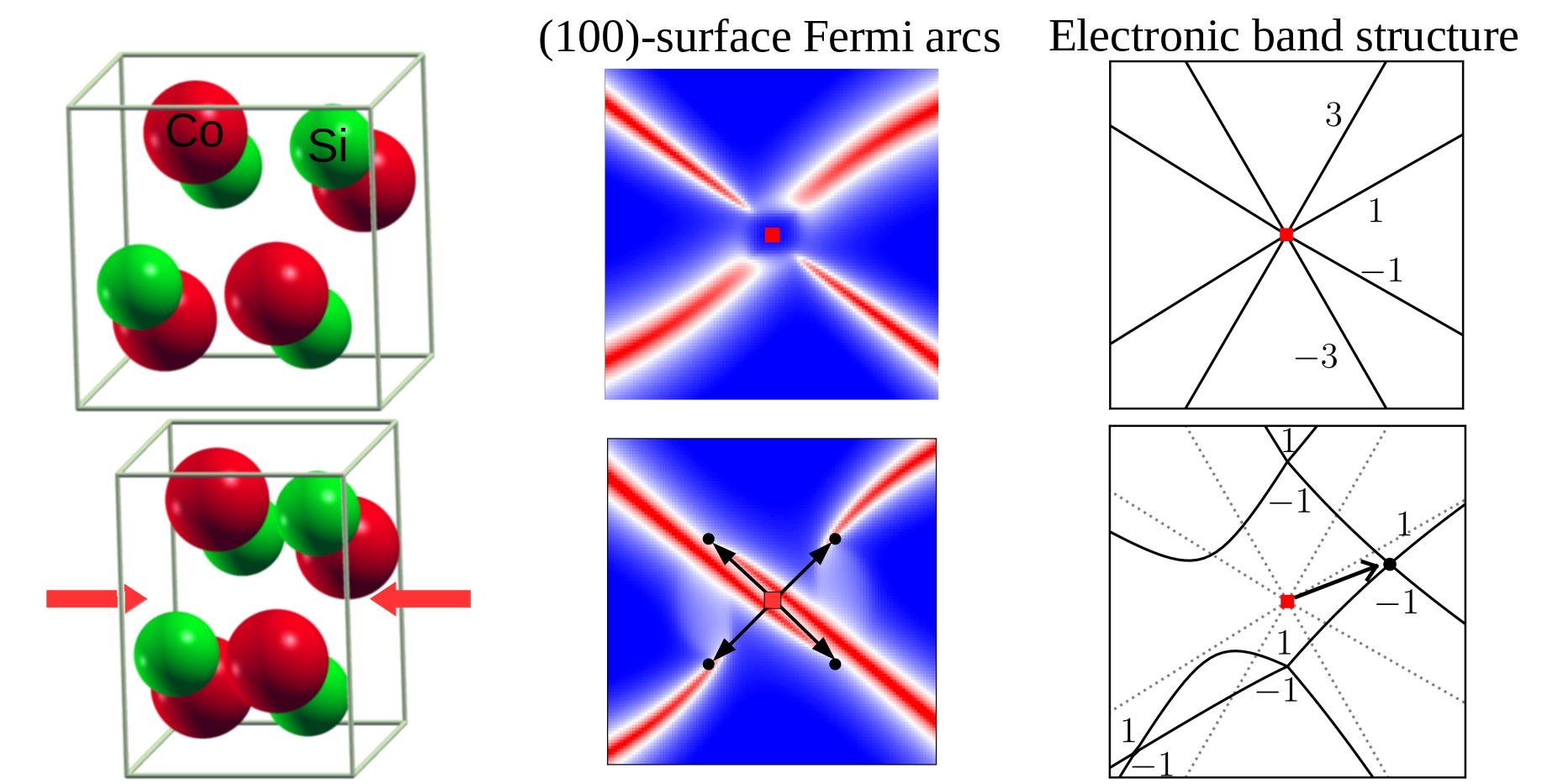
3). The unit cell and the Brillouin zone of CoSi are shown in Figure 1a,b. The band structure, magnetic, optical, transport and, in particular, thermoelectric properties of CoSi have been extensively studied [1,2,3,4,5,6,7,8,9,10,11,12,13,14,15]. Initially, the interpretation of experimental results was based on a simple semimetallic band structure model with small energy overlap of parabolic valence and conduction bands [1,2]. With the development of first-principle density functional theory (DFT) methods, a more realistic CoSi band structure has emerged [3,4,5,6,7,8]. Band structures calculated with and without the account of spin-orbit coupling (SOC) are plotted in Figure 1c,d, respectively. Earlier calculations [3,4] without the account of SOC revealed the presence of multiple band crossings at the Γ and R points of the Brillouin zone, but they did not consider the topology of the band structure. The symmetry analysis allowed to predict the existence of chiral fermions and multifold band crossings with high topological charges in crystals belonging to several space groups (including space group #198) in the presence of time-reversal symmetry [16,17]. In CoSi, multifold linear band crossing and spin texture was initially investigated around the Γ point, based on first-principle fully-relativistic calculations [5]. Later, detailed studies of band structure topology were made for CoSi [6,8] and for isostructural RhSi [7]. Effective k · p Hamiltonians around the time-reversal invariant momentum (TRIM) points were written down in Ref. [17] for R point and in Ref. [8] for Γ point. It was shown [6,8] that the topological charges at the Γ and R points are equal to ± 4 and there are four surface Fermi arcs, connecting projections of these points on the surface Brillouin zone. Because spin-orbit coupling in CoSi is not strong, the Chern numbers were also calculated without SOC [6,18]. It was shown that multifold nodes have large topological charges of ± 2 even without SOC (see Figure 1d for illustration). The existence of multifold fermions and surface Fermi arcs in CoSi was recently confirmed by angle resolved photoemission spectroscopy (ARPES) [18,19,20].
The theoretical study of the band structure beyond DFT, taking into account dynamic on-site correlations of d-electrons, revealed that, in contrast to FeSi, the electronic states in CoSi are only moderately influenced by electronic correlations [21]. Band broadening in CoSi is small in the range of ±0.3 eV near the Fermi level and decreases with the temperature. Thus, DFT description of CoSi band structure should give quite accurate results, that is confirmed by ARPES experiments [18,19,20] and by the better agreement of calculated lattice constants and elastic modules with experimental results for CoSi, compared to other monosilicides of the elements of the 4th period [22].
New information on the band structure of CoSi prompted to study the manifestation of its non-trivial topology and provided a base for correct interpretation of experimental results on conventional transport properties of the compound. For example, the account of real band structure and energy dependent relaxation time allowed to adequately explain the concentration dependencies of thermoelectric and galvanomagnetic properties of Co 1 x Fe x Si and Co 1 x Ni x Si alloys [10,11,12]. Recently, the effects of nonstoichiometry of CoSi-based materials on thermoelectric [9] and magnetic [14] properties were studied. In particular, in samples with the excess of Co, magnetically ordered states with helical and skyrmionic spin structures were observed near room temperature [14]. Quantum oscillations of thermopower with a beating pattern were observed in high-quality CoSi crystals [13]. They were successfully interpreted by the coexistence of two close Fermi surfaces in agreement with DFT results for the band structure. The influence of chiral fermions and charge density waves on magnetic field dependent electrical transport was studied in [23]. The experimental and theoretical investigation of optical conductivity of CoSi revealed various exotic multifold quasiparticles [15]. Moreover, low-frequency part of optical conductivity spectrum confirmed the existence of previously experimentally unobserved four-fold spin-3/2 node at the Γ point [15].
As the features of the band structure topology are due to particular crystal symmetry of CoSi, it is interesting to investigate the evolution of these properties when the symmetry changes. Such changes can appear due to mechanical stress, for example, in thin film devices or experimental setups, and can be important for device operation or interpretation of experimental data. In addition to the change of symmetry, mechanical deformation, in principle, can lead to the opening of a gap in the energy spectrum and the disappearance of the topological nodes. The possibility of using CMOS-compatible CoSi thin films for thermoelectric and sensor applications were considered recently in Ref. [24]. The stability of CoSi under hydrostatic pressure was theoretically investigated in Ref. [25], where it was predicted that the transition to CsCl structure ( P m 3 ¯ m ) take place at hight pressure of 270 GPa. In the present work, we theoreticaly investigate another possibility—the change of band structure under uniaxial strain. In contrast to isotropic strain, uniaxial deformation changes the crystal symmetry even at low pressure. We considered deformation in [100], [110] and [111] directions. Based on symmetry analysis, the k · p Hamiltonian, taking into account deformation, was constructed for both the Γ and R points. Combining ab initio calculations, analytical model and symmetry considerations, the band splitting at the Γ and R points, the types of nodes arising from multifold band crossings and their energy and k-space positions were carefully studied both with and without SOC.

2. Method of Calculation

DFT calculations were performed in an integrated suite of Open-Source computer codes for electronic-structure calculations—Quantum ESPRESSO (QE) [26], using fully relativistic optimized normconserving Vanderbilt pseudopotentials (ONCV) [27]. The plane wave cut-off energy was 80 eV. The calculations were performed on 8 × 8 × 8 Monkhorst–Pack(MP) grid with the optimized lattice parameter a 0 = 4.438 Å. Four atomic positions of each of atomic species in the unit cell of undeformed CoSi are ( x A , x A , x A ) , ( x A + 1 / 2 , x A , x A + 1 / 2 ) , ( x A , x A + 1 / 2 , x A + 1 / 2 ) , and ( x A + 1 / 2 , x A + 1 / 2 , x A ) . Their optimization gives x Co = 0.144 , x Si = 0.843 .
Under uniaxial deformation, we set the unit cell parameters based on corresponding strain tensor and performed the relaxation of atomic positions, that allowed to determine the space group of deformed crystal.
For detailed study of the band structure, we performed Wannier interpolation using Wannier90 [28]. The position of nodes, topological charges and Fermi arcs were calculated using WannierTools [29] software package.
In order to analyze low-energy excitations around the nodes at Γ and R points, we constructed k · p Hamiltonian H ^ in the presence of deformation from symmetry considerations. This allowed to independently verify the position of nodes and topological charges. As the effects of strain was assumed to be small, we considered only zeroth order in k terms in Hamiltonian proportional to strain tensor [30,31]: D i j ϵ i j , where ϵ i j are strain tensor components and D i j are deformation potential parameters. The independent terms can be identified, applying symmetry operations of the considered space group (P2 1 3, #198), as it was made for the construction of Hamiltonian without stain [8,16,17]. We took into account that ϵ i j is transformed under symmetry operations as a product of wave vector components k i k j , and used irreducible representations of space (double space) groups from Bilbao Crystallographic Server [32] for the case without (with) spin-orbit coupling. Since the spin-orbit coupling is also small in CoSi, we did not consider terms in H ^ that depend on both strain and spin-orbit interaction. As will be seen from what follows, this approximation is sufficient.
The form of obtained Hamiltonians and their parameters are given in Appendix A. In the equations we used eV as units of energy. The wave vector components k i , i = 1 , 2 , 3 (in crystal coordinates) are measured in fractions of the reciprocal lattice vectors. The wave vector components k i , i = x , y , z (in Cartesian coordinates) are measured in the units of 2 π / a 0 = 1.416 Å 1 . If not stated otherwise, the latter units were used in band structure plots.
The deformation potential parameters were obtained using shifts of energy levels from ab initio calculations of undeformed and deformed crystal. The deformation potential parameters at the diagonal elements of strain tensor ϵ i i in k · p Hamiltonian determine the absolute shift of energy levels upon deformation. For CoSi, as metallic material, the absolute shift of energy level ϵ n due to deformation can be calculated as Δ ϵ n = ( ϵ n ( d ) ϵ F ( d ) ) ( ϵ n ( u ) ϵ F ( u ) ) , where ϵ n ( d ( u ) ) are energy levels in deformed (undeformed) crystal, and ϵ F ( u ( d ) ) are corresponding Fermi levels (see Appendix B for details).

3. Results without SOC

The band structure of CoSi without SOC features a triply-degenerate energy level at the Γ point close to the Fermi level. It is plotted in the inset of the Figure 1d and in the Figure 2 with dotted lines. The wave functions are transformed according to the three-dimensional single-valued representation Γ 4 of the little group of the Γ point of P 2 1 3 (#198). The low-energy excitations around this point can be considered as effective spin-1 quasiparticles [33]. The topological charges of lower and upper linear branches are 2 and 2 respectively, while nearly flat band has zero charge.
Let us consider the simplest deformation of a crystal along the crystallographic direction [ 100 ] . When stretched along this direction, the spatial symmetry of group P 2 1 3 (#198) is lowered to P2 1 2 1 2 1 (#19), and essential remaining symmetry elements are: { C 2 x | 1 2 0 1 2 } , { C 2 y | 1 2 1 2 0 } , { C 2 z | 0 1 2 1 2 } . At the Γ point, this group has only one-dimensional irreducible representations and, using character theory, we can expect that the three-dimensional representation Γ 4 of the space group P 2 1 3 (#198) splits into three one-dimensional representations of P 2 1 2 1 2 1 (#19) as: Γ 4 Γ 2 + Γ 3 + Γ 4 . As Γ 2 ( 3 , 4 ) are real single-valued representations, they are not combined due to time-reversal symmetry (TRS) [32].
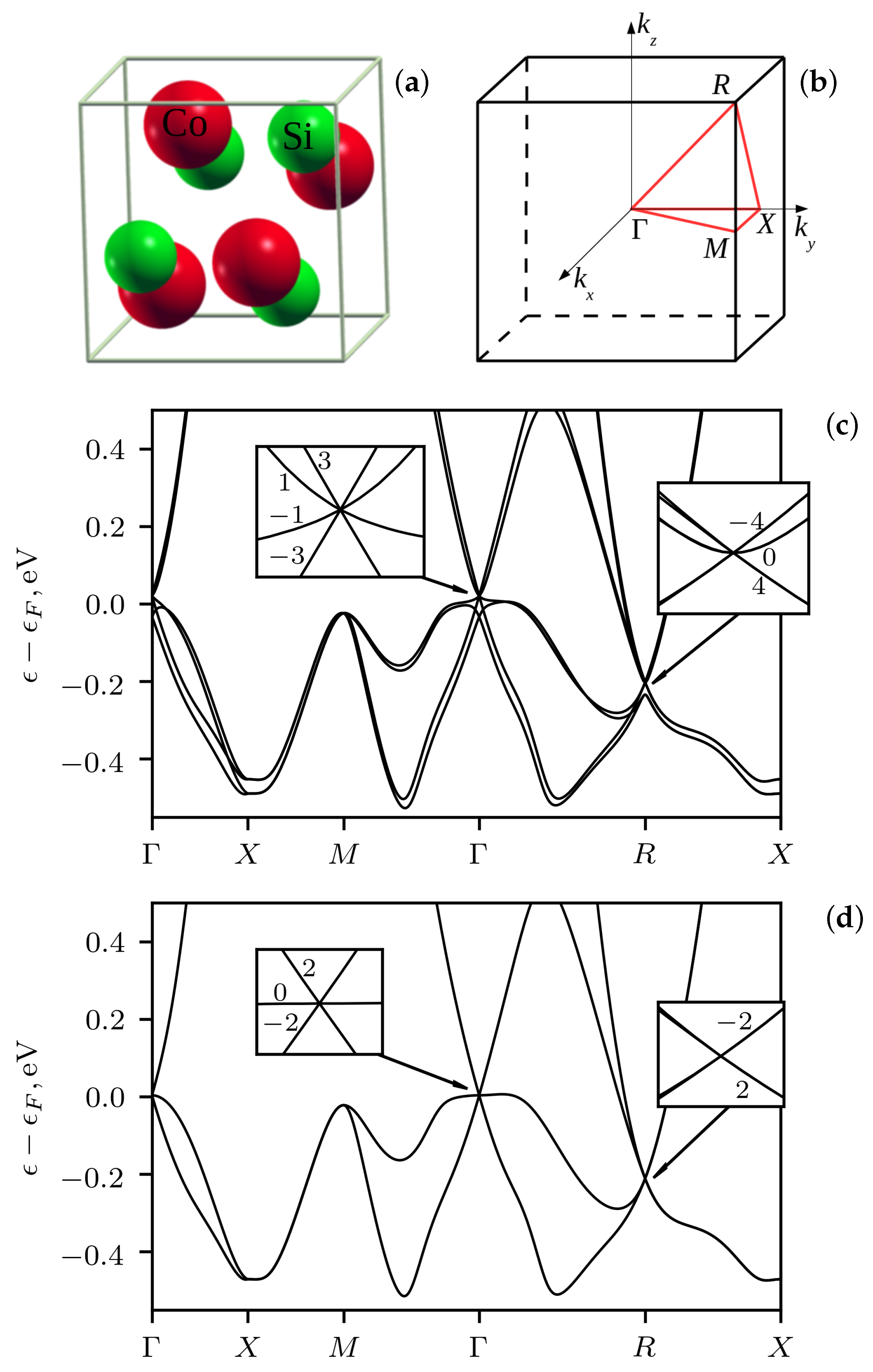
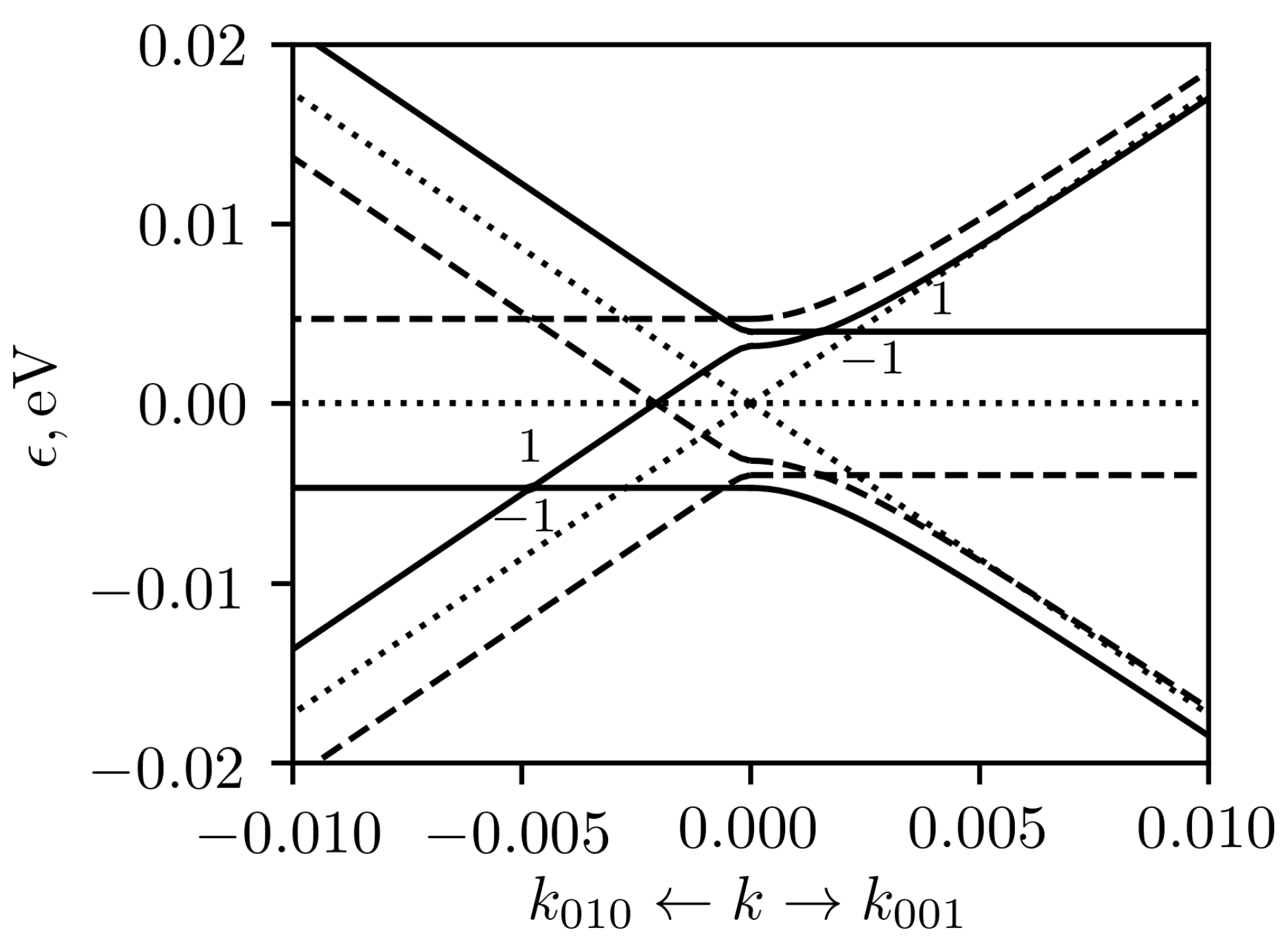
Thus, without taking into account the spin-orbit interaction, the triply-degenerate level at the Γ 
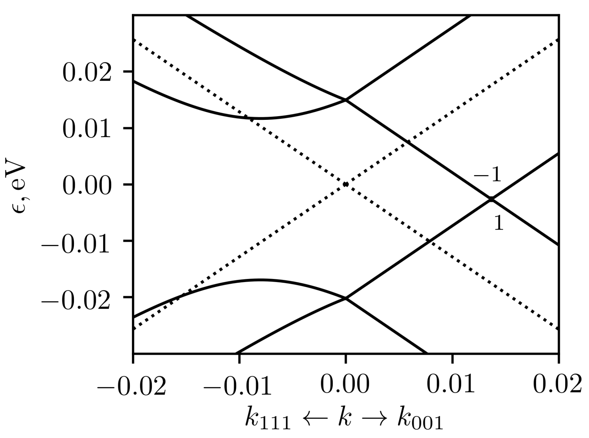
point is split into three with different energies. The low-energy band structure around the Γ point in CoSi under 1% uniaxial deformation in [100] direction is shown in the Figure 2 with solid lines for compressive strain and with dashed lines for tensile strain.
As the time-reversal symmetry is preserved in the considered cases, the whole energy spectrum around the TRIM point is symmetric with respect to the change of the sign of the wave vector k k . In addition, our k · p Hamiltonian is linear both in k and in components of deformation tensor ϵ ^ . Hence, the low-energy band structure for stretched crystal can be obtained from the band structure of compressed crystal by changing the sign of energy ϵ ( k , ϵ ^ ) = ϵ ( k , ϵ ^ ) , that can be seen by comparing solid and dashed curves in the Figure 2. It should be noted that this conclusion applies to all considered cased with the exception of eight-band Hamiltonian around the R point including SOC, as the latter contains terms independent of both wave vector and deformation tensor.
In compressed crystal there are nodes shifted in k z and k y directions upwards and downwards in energy relative to unstrained case, as shown in Figure 2. The topological charges of both nodes are equal to ± 1 . In stretched crystal, the sign of the energy changes, and the nodes swap. In both cases, we have two doubly degenerate (spinless) nodes at the same energy at the positions ± k n z with the total topological charge of ± 2 and similar nodes at positions ± k n y . In the case, when only ϵ 11 = e is not zero, the node positions for small deformation can be obtained from eigenvalues of k · p Hamiltonian, and are equal to k n z = ( D 1 D 2 ) ( D 3 D 2 ) e / v and k n y = ( D 3 D 1 ) ( D 3 D 2 ) e / v . In these expressions v is the Fermi velocity at the Γ point in unstrained crystal and D i are the deformation potential parameters, defined in Appendix A after Equations (A1) and (A2).
It can be seen also, that the dispersion around doubly degenerate nodal points is tilted. As was shown in the Ref. [34], the general form of the Hamiltonian for Weyl point is the following: H ( k ) = i , j k i A i j σ j , where A i j is a 3 × 4 matrix of coefficients and σ j are the 2 × 2 unit matrix and the three Pauli matrices for j = 0 and j = 1 , 2 , 3 respectively. The spectrum can be written as ϵ ± ( k ) = T ( k ) ± U ( k ) , where T ( k ) = i = 1 3 k i A i 0 and U ( k ) = j = 1 3 i = 1 3 k i A i j 2 . The nodal point is of the type II if there is a direction, in which T ( k ) > U ( k ) . In the present case, it can be shown that in linear approximation T ( k ) = U ( k ) in k 010 or k 001 directions independently of the magnitude of strain e. Thus, under strain the nodal points are at the border of transition from type I to type II nodal points. However, it should be emphasized that, in contrast to ordinary type-II Weyl fermions, fermion states discussed here are spin degenerate.
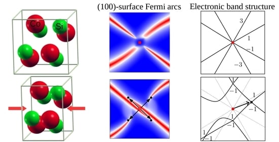
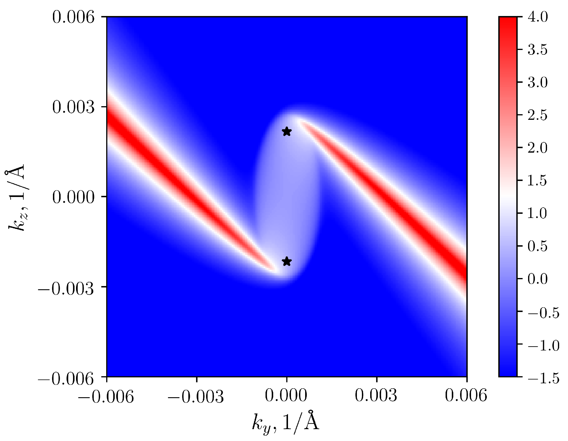
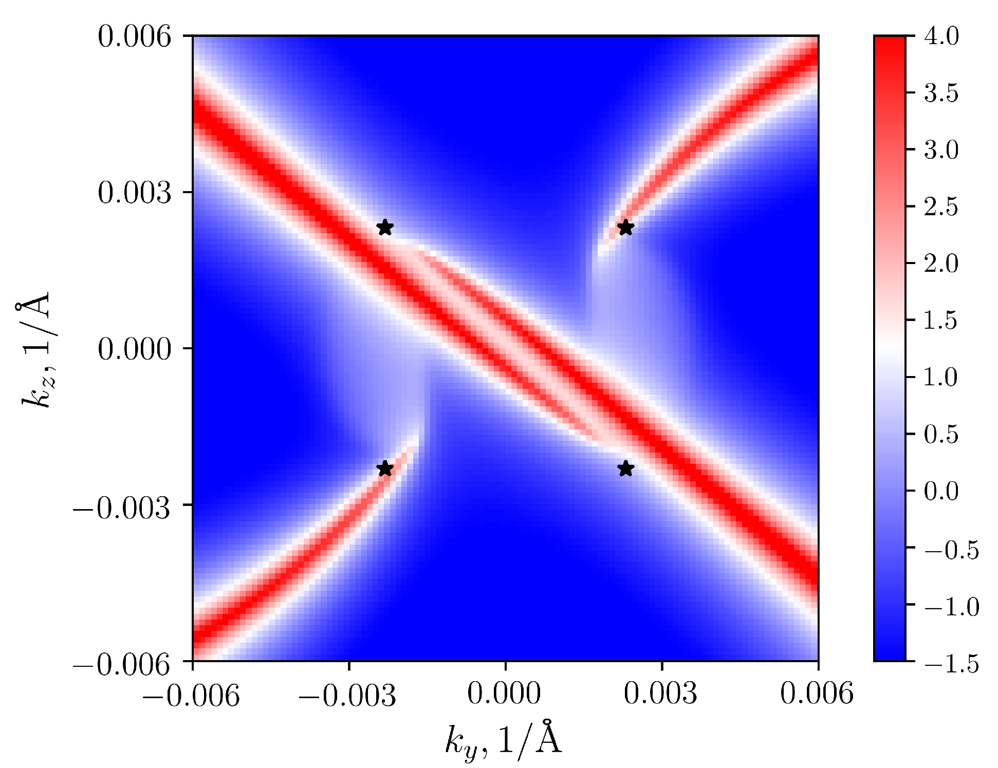
The shift of nodes in reciprocal space implies the modification of the shape of surface Fermi arcs, that should emanate from the projections of the nodal points on the (100) surface Brillouin zone. In CoSi, it appeared that due to large extension of the Fermi arcs between the projections of the Γ and R point, their general shape changes quite moderately (at the scale of the full Brillouin zone) compared to undeformed case, presented in Refs. [6,8]. Therefore here we illustrate their variation around the Γ point only for several selected cases. The Figure 3 shows the Fermi arcs in the (100) surface Brillouin zone for the case of compressive deformation in the [100] direction for e = 0.01 . For better visualisation, Fermi level was shifted to the energy of nodal points. The position of nodes, obtained by k · p calculations, are plotted in the figure by black asterisks. It can be seen, that two nodes are shifted along k z direction, and their positions correlate with the sources of two surface Fermi arcs.
When deforming in [ 110 ] direction, off-diagonal elements of the strain tensor begin to play a role. The spatial symmetry of deformed cobalt monosilicide is described by the space group P2 1 (#4) with the only symmetry element { C 2 z | 00 1 2 } (except lattice translations). Therefore, without taking into account the spin-orbit interaction, the three-dimensional representation Γ 4 of the group P 2 1 3 ( # 198 ) splits into three one-dimensional representations of P 2 1 ( # 4 ) as: Γ 4 Γ 1 + 2 Γ 2 . In this way, the degeneracy at the Γ point is completely lifted, as in the case of the deformation along the main unit cell directions. In the most simple case, compatible with considered symmetry, where the only non-zero components of stain tensor are ϵ 12 = ϵ 21 = e / 2 , two effective spin-1/2 nodes symmetrically diverge from Γ point along [110] ([1 1 ¯ 0]) crystallographic direction and shift to lower energies in the case of compressive (tensile) strain e < 0 ( e > 0 ). Similar nodes appear at higher energies but they are shifted along [1 1 ¯ 0] ([110]) directions for e < 0 ( e > 0 
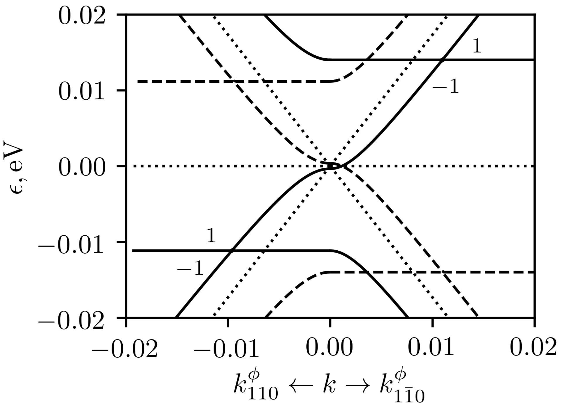
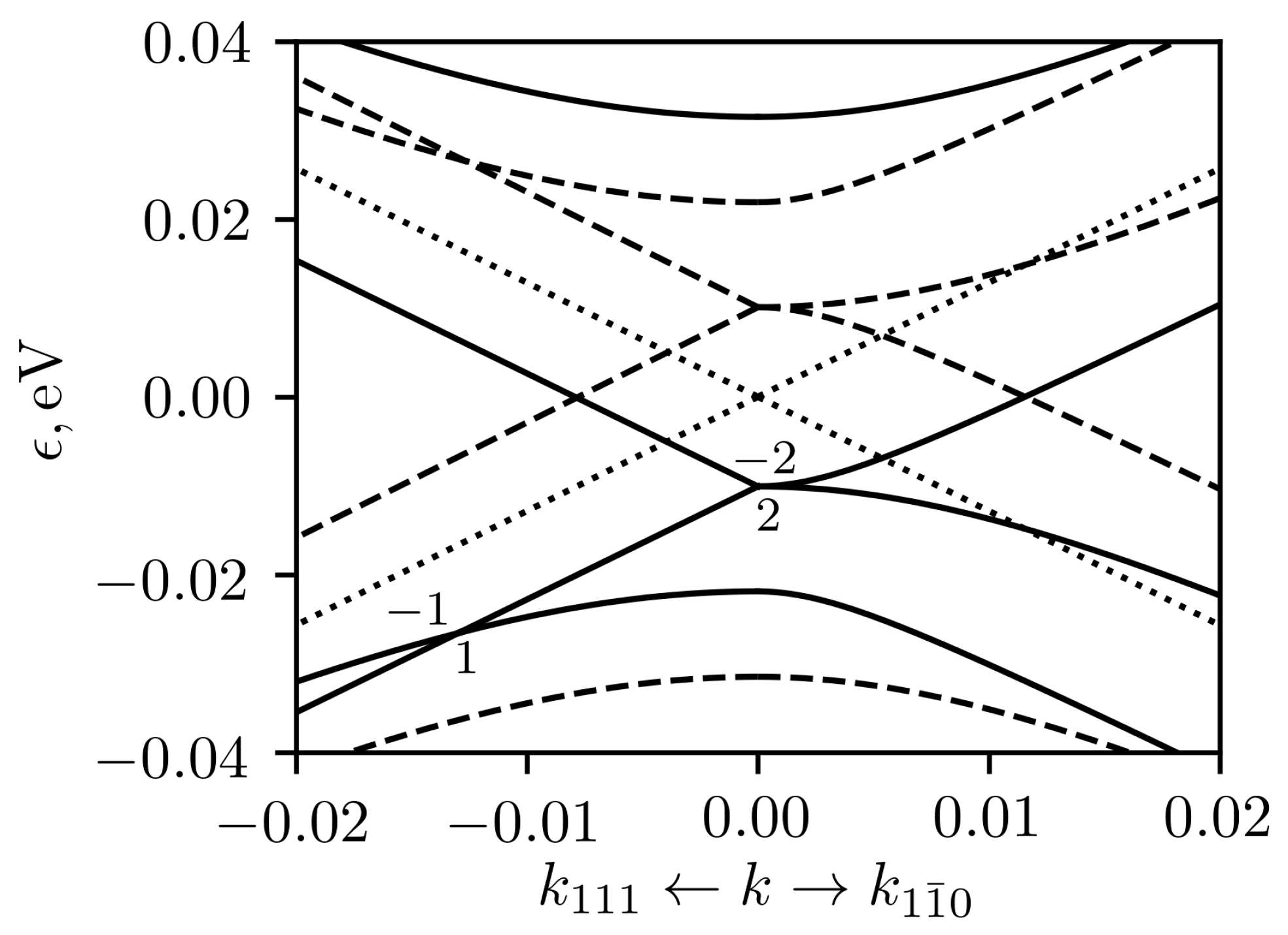
). In more general case, when ϵ 11 = ϵ 22 = ϵ 12 = e / 2 , that corresponds to the absence of deformation in directions normal to [110], the nodes split along the line, that is rotated by a small angle (about ϕ = 5 ° at e = 0.01 ) from [110] ([1 1 ¯ 0]) axis. Let’s denote these directions by k 110 ϕ ( k 1 1 ¯ 0 ϕ ). The low-energy band structure for these directions and topological charges are given in the Figure 4. The situation is somewhat similar to [100] case (see, 
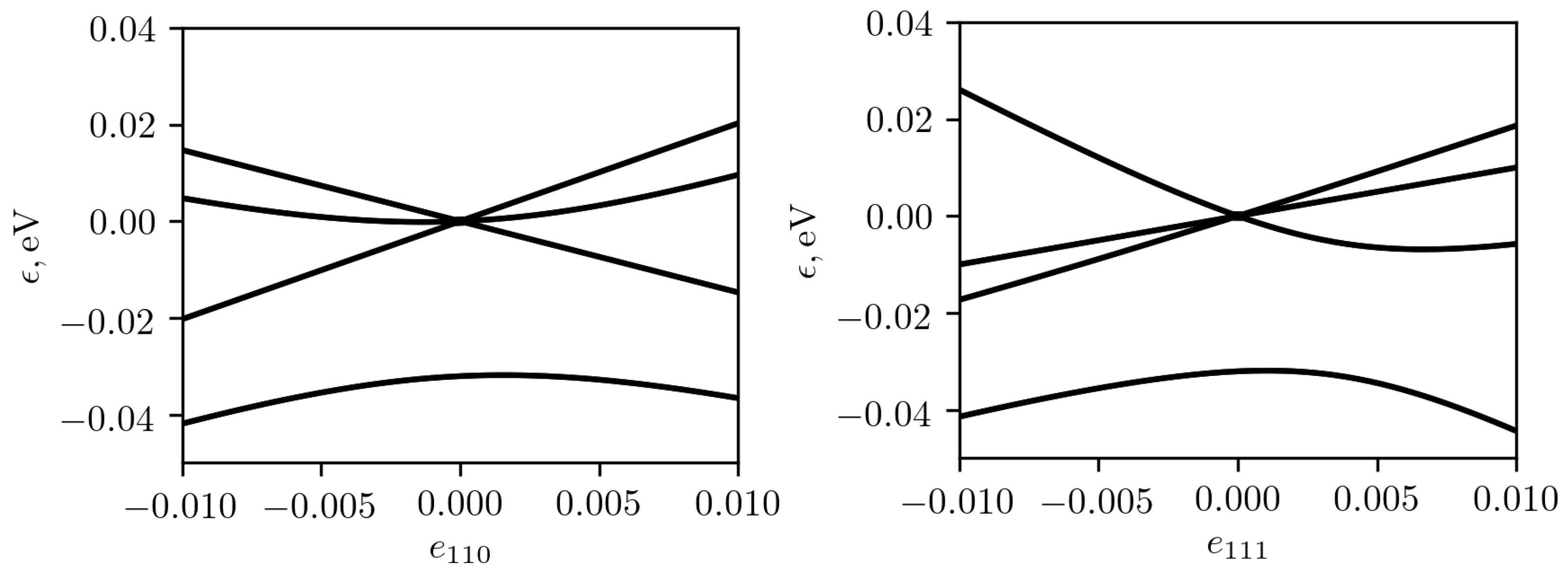
Figure 2), but the shift of nodes in both energy and k-space are larger. In this case we obtain again effective spin-1/2 nodes with the tilt intermediate between tilts of the type-I and type-II nodes. The total topological charge of each pair of the nodes is ± 2 .
The deformation along the [ 111 ] crystallographic direction needs special consideration for CoSi. When deformed in [111] direction, the symmetry of cobalt monosilicide is reduced to R 3 ( # 146 ) space group with the single 3-fold rotation axis. Character theory suggests that without SOC, the three-dimensional representation Γ 4 of P 2 1 3 ( # 198 ) space group splits into three one-dimensional representations of R 3 ( # 146 ) as: Γ 4 Γ 1 + ( Γ 2 + Γ 3 ) . Since the representations Γ 2 and Γ 3 are mutually conjugate, they should be combined due to time reversal symmetry. The triply degenerate level is split into two (nondegenerate and doubly degenerate) levels, in contrast to other types of deformation in which the degeneracy is completely lifted at the Γ 
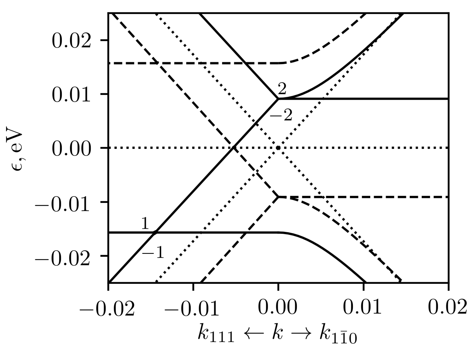
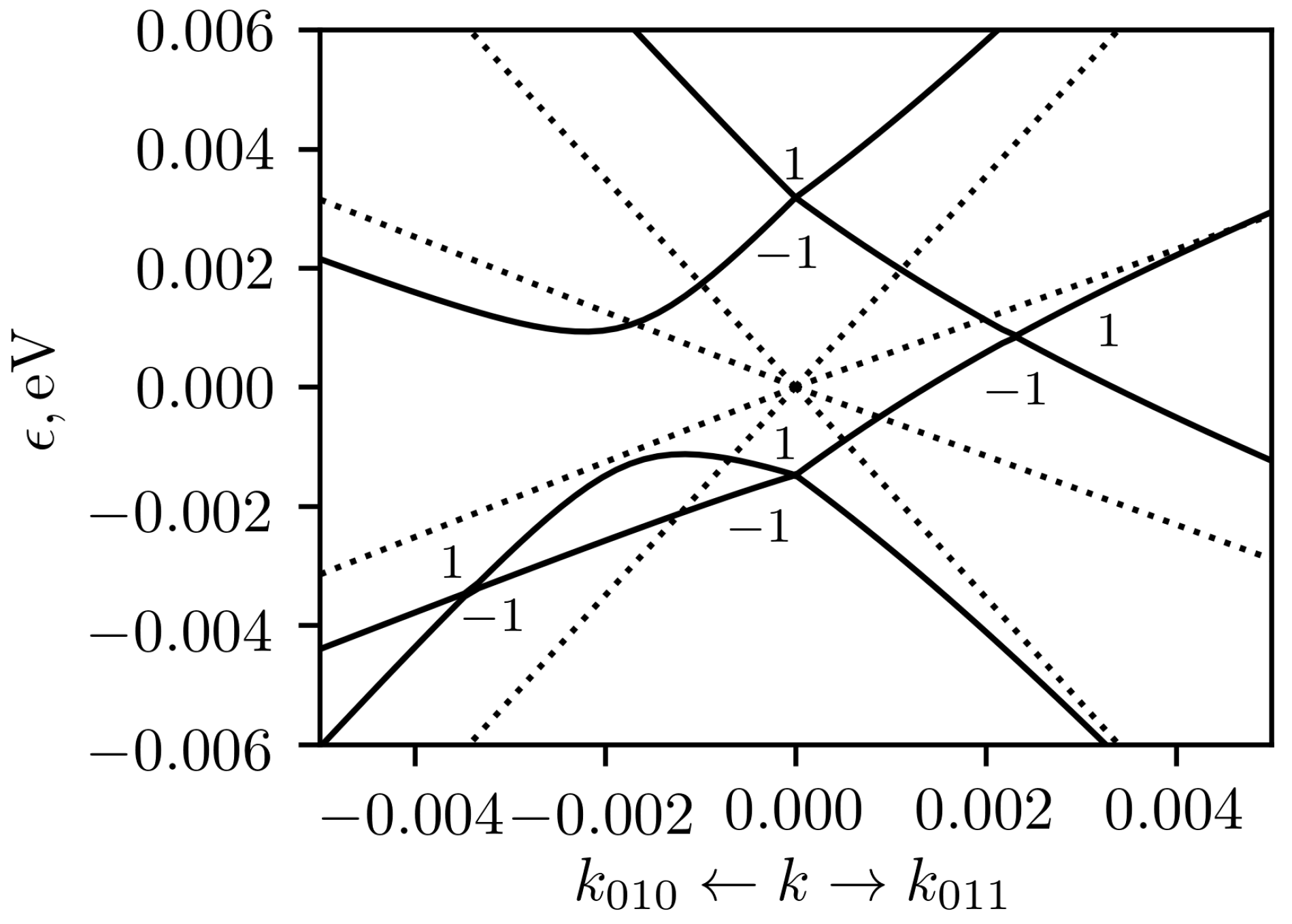
point. In this case, strain tensor was taken in the form ϵ i j = e / 3 for all i , j . In deformed crystal, one unusual node is located at the Γ point and two other nodes are displaced along the [111] direction at the positions ± k n , 111 with k n , 111 = D 4 e / v ( 1 + e ) (see the Figure 5). In this case we obtained one node with topological charge ± 2 at the Γ point and two nodes with charges ± 1 at ± k n , 111 points. The spectrum for compressive and tensile strains are again can be obtained by the energy sign change. Thus the number of nodes between the two upper bands depends on the sign of deformation 
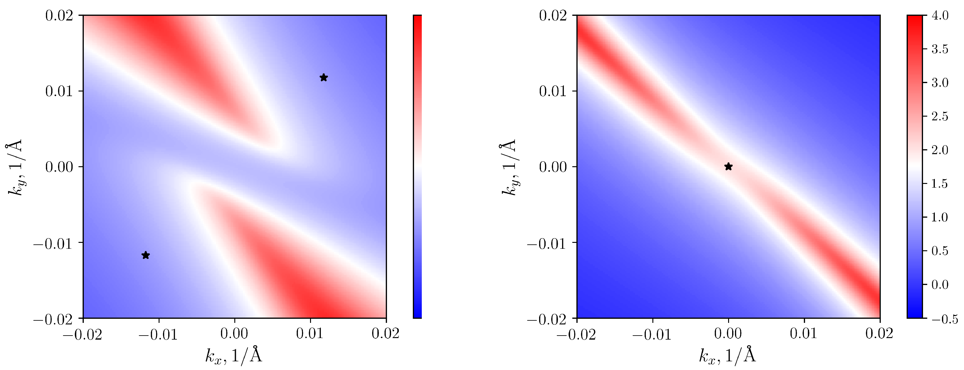
e. Another way to see this result is to plot Fermi arcs in the (001) surface Brillouin zone for compressive and tensile strain (see Figure 6). Consider a compressed crystal. Below the Fermi level, there are two nodes shifted in [111] direction. Their projections on (001) plane are sources of two Fermi arcs (left panel). The starting points of the arcs are shifted towards the projections of the nodes (black asterisks) but do not coincide with them exactly, since the Fermi level is located above these nodes. In the case of expansion, the node with topological charge of 2 is below the Fermi level, and both Fermi arcs start from the Γ point (right panel).
The fermions around the node with topological charge of 2 at the Γ point are similar to that of quadratic double-Weyl fermions in SrSi 2 , described in Ref. [35], but they arise for another reason. In SrSi 2 without SOC, on the four-fold rotation axes of the crystal, there are two-fold band crossings with linear dispersion. The bands are spin degenerate. The account of spin-orbit coupling adds terms independent of wave vector to the Hamiltonian that leads to a partial lifting of the degeneracy and to a change of linear dispersion to quadratic in certain directions. In CoSi, the k-independent terms in H ^ appear due to strain even without SOC. Counting energy relative to the charge-2 node in the Figure 5, the dispersion in [111] direction remains linear: Δ ϵ = ± k 111 v ( 1 + e ) . While, in perpendicular direction, it becomes quadratic, Δ ϵ = D 4 e / 2 sign ( e ) ( D 4 e / 2 ) 2 + ( k , 111 v ) 2 or flat. Thus, in CoSi under [111] deformation, there is a strain induced transition from spin-1 quasiparticles to quadratic effective-spin-1/2 fermions.
Let us now consider low-energy band structure around the R point without spin-orbit coupling. In this case in unstrained CoSi, the energy level at the R point is four-fold degenerate not considering spin (see Figure 1d). Low energy excitations around the R point are double spin-1/2 fermions [33] with the Chern number −2 [6]. The wave functions are transformed according to the direct sum of single-valued mutually conjugated complex two-dimensional representations R 1 and R 3 , combined due to TRS. The switching to P 2 1 2 1 2 1 (#19) space group under [100] uniaxial deformation does not lead to the energy level splitting, because the representation R 1 + R 3 is transformed into the direct sum of the pseudoreal representations R 1 + R 1 of P 2 1 2 1 2 1 . Thus the node at the R point remains intact.
Under uniaxial [110] stress, the space group P 2 1 3 is reduced to P 2 1 group and the R point goes into the E point, which is also located at the vertex of the deformed Brillouin zone. The representation R 1 + R 3 is transformed into 2 ( E 1 + E 2 ) . The E 1 and E 2 representations of P 2 1 are one-dimensional and mutually conjugated, therefore they are combined due to TRS. Thus, four-fold degenerate energy level splits into two doubly degenerated levels (see Figure 7). The nodes are split along k z direction and are situated at k n z = ± D 2 2 + D 3 2 e / 2 v , where deformation potential constants are given in Appendix A after Equation (A3). The topological charges of these two nodes are 1 . Two crossing points at the R point (E point of P2 1 2 1 2 1 space group) in the Figure 7 are not nodes as the states are degenerate on the ( 001 ) surface of the deformed Brillouin zone.
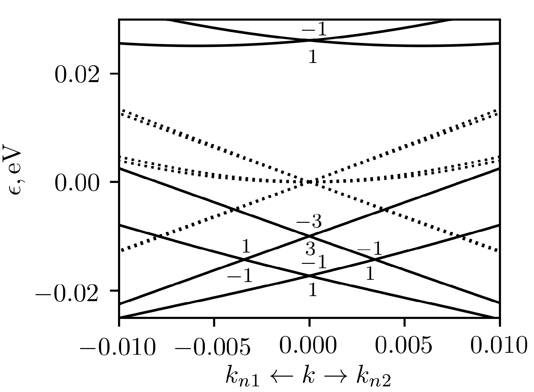
In the case of [111] deformation, the four-fold degenerate level at the R point splits into three levels (two nondegenerate, and one doubly degenerate) at the corner (T point) of deformed Brillouin zone (see Figure 8). Representations transform according to the expression R 1 + R 3 2 T 1 + ( T 2 + T 3 ) . All representations at the T point are one-dimensional, but T 2 and T 3 are mutually conjugated and should be combined due to TRS. Similarly to the case of Γ point, doubly degenerate node at the T point has topological charge of 2 and has quadratic dispersion in the direction perpendicular to [111]. There are also nodes with tilted dispersion, shifted in the [111] direction by k n , 111 = ± ( 2 D 2 2 D 3 2 ) e / 2 3 D 2 v . Their topological charge is 1 .

4. Results with SOC

Taking into account the spin-orbital coupling in the crystal without deformation, the 6-fold degenerate level at the Γ point splits into a doublet and 4-fold degenerate levels. Their wave functions are transformed according to the Γ ¯ 5 irreducible representation and mutually conjugated Γ ¯ 6 and Γ ¯ 7 irreducible representations, combined due to time-reversal symmetry [8]. The low-energy excitations around the 4-fold degenerate node at the Γ point are spin-3/2 fermions [6,33] with topological charge of 4. Its dispersion is shown in the Figure 1c, and is also plotted with dotted lines in the Figure 9. The doublet does not move from the Γ point due to deformation, so we consider in more details the evolution of fourfold node at the Γ point under the influence of deformation along the main crystallographic directions.
Under the deformation along [100] the fourfold degenerate level splits into two twofold degenerate levels, both corresponding to Γ ¯ 5 representation of the P 2 1 2 1 2 1 (#19) group, as this two-dimensional representation is time-reversal invariant. The low-energy Hamiltonian for these levels is given by Equations (A4) and (A5) of Appendix A. When the only non-zero component of deformation is ϵ 11 = e , the gap between two levels at the Γ point is equal to 2 D 3 e . In general case, it is equal to 2 D 3 e ( 1 + ν P ) , where ν P is the Poisson ratio. The low-energy spectrum is shown in the Figure 9. The doublets at the Γ point form Weyl nodes with unit topological charge. Four nodes are shifted from the Γ point along the diagonals of the k y k z plane and each of them has a unit topological charge. In addition, two Weyl nodes shifted from the Γ point in the ± k y directions appear between two lower branches of the spectrum, and two similar Weyl nodes shifted in the ± k z directions (not shown in Figure 9) appear between two upper branches of the spectrum. The tensile and compressive strain spectra differ from each other by a change in the sign of the energy.
Without deformation, there are four surface Fermi arcs, emanating from the projection of the nodal point at Γ , as the topological charge is 4. The shift of the node positions for [100] deformation ( e = 0.01 ) is accompanied by a change in the surface Fermi arcs, shown in the Figure 10, for the case when the Fermi level coincides with the nodes located along the diagonals of the k y k z plane. The projections of the nodes are marked with asterisks. Their positions, calculated by the k · p method, quite well coincide with the sources of four Fermi arcs.
Considering the deformation along [110] axis, we found similar splitting of four-fold degenerate level at the Γ point into 2 doublets: Γ ¯ 6 + Γ ¯ 7 2 ( Γ ¯ 3 + Γ ¯ 4 ) , where irreducible representations Γ ¯ 3 ( 4 ) of the space group P 2 1 ( # 4 ) are one-dimensional and combined together due to TRS. The energy gap at the Γ point is equal to e D 2 2 + D 3 2 . When the only non-zero components of stain tensor are ϵ 12 = ϵ 21 = e / 2 , the four-fold degenerate node splits into 4 nodes, moving along crystallographic directions [100], [ 1 ¯ 00 ], [010], [0 1 ¯ 0 ] by the distance D 2 e / 2 b 2 a 2 . Due to distortion, small deviation from corresponding Cartesian axis appears by an angle of ϕ = arctan ( e / 2 ) , which is equal, for example, to 0.3 ° at e = 0.01 . In the case of the absence of deformations in the directions, normal to [110], when ϵ 11 = ϵ 22 = ϵ 12 = e / 2 , the shift of energy levels due to volume change leads to additional deviation of nodes from Cartesian axes, which is about ϕ = 6 ° at e = 0.01 . Similar to the case of [100] deformations, there are also two Weyl nodes below and two Weyl nodes above the node in unstrained crystal, but here they are shifted close to the diagonals of k x k y plane. To within a change of the directions of node shifts, the low-energy spectrum around the Γ point for this case is qualitatively very similar to the case of [100] deformations (see the Figure 9).
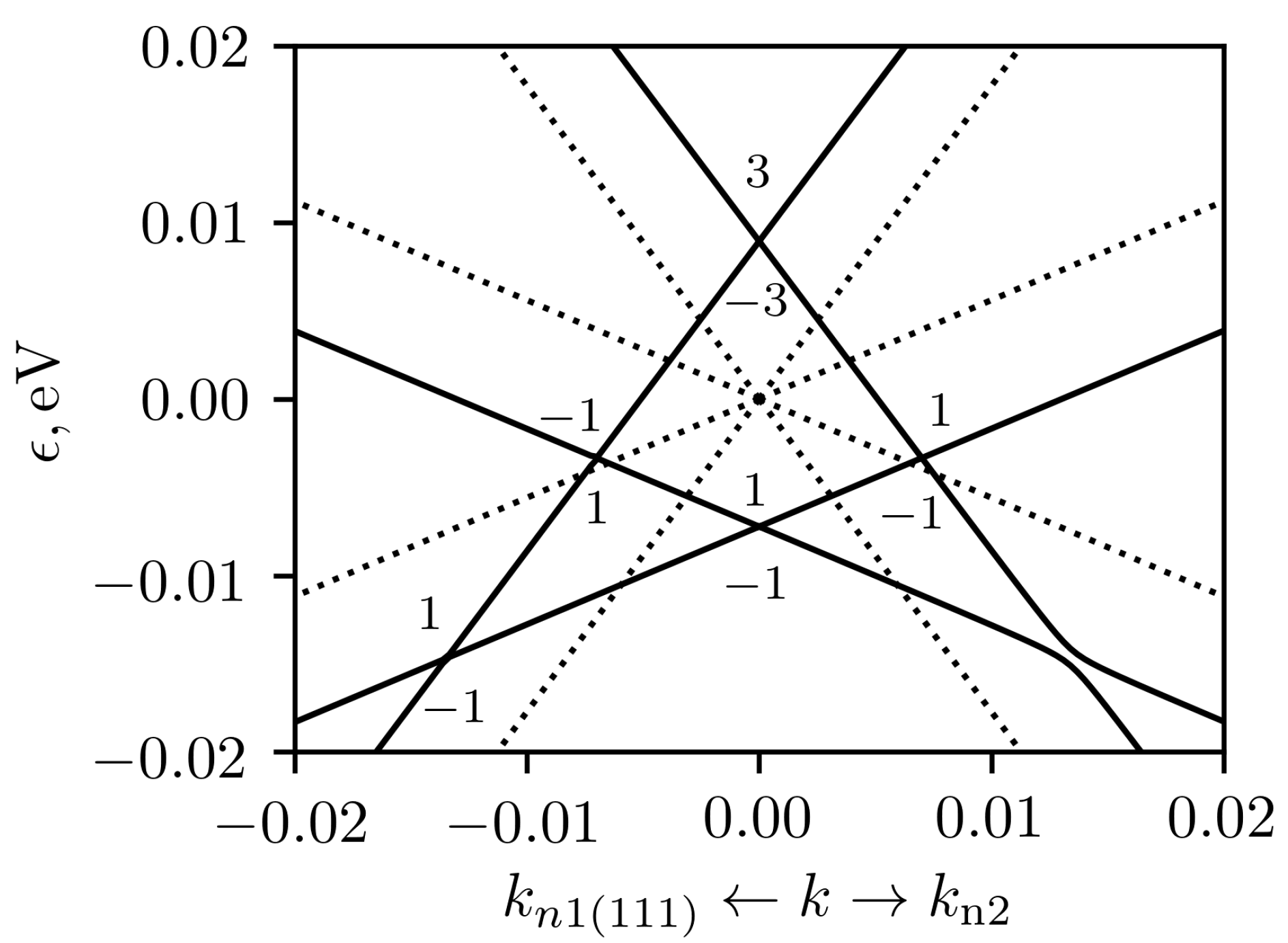
When the stress is applied along [111] axis, we obtain similar 4-fold level slitting into two doublets at the Γ point with Γ ¯ 6 + Γ ¯ 7 ( Γ ¯ 4 + Γ ¯ 4 ) + ( Γ ¯ 5 + Γ ¯ 6 ) , where all irreducible representations Γ ¯ 4 ( 5 , 6 ) of the space group R 3 (#146) are one-dimensional. Γ ¯ 4 is real and it is doubled due to TRS, while Γ ¯ 5 ( 6 ) are complex conjugated and they are combined together due to TRS. These two band crossings at the Γ point are shown in the Figure 11. The lower one is a Weyl node. The node at higher energy has linear dispersion in the [111] direction and nonlinear dispersion in the perpendicular plane (this branch is not shown in the figure). It looks like the triple-Weyl node [36,37,38] with topological charge ± 3, but it is located at the TRIM point. In addition, near the Γ point, there are two groups of nodes connected by time-reversal symmetry. Each of these groups consist of 4 nodes. One of them k n 1 is shifted from the Γ point along the [111] axis by a distance k = D 2 e ( a + a 2 + 2 b 2 ) / 3 b 2 , which is about 0.007 at | e | = 0.01 (see Figure 11). In the case of compressive (tensile) strain the energy of the node shifts downwards (upwards) relative to the node at the Γ 
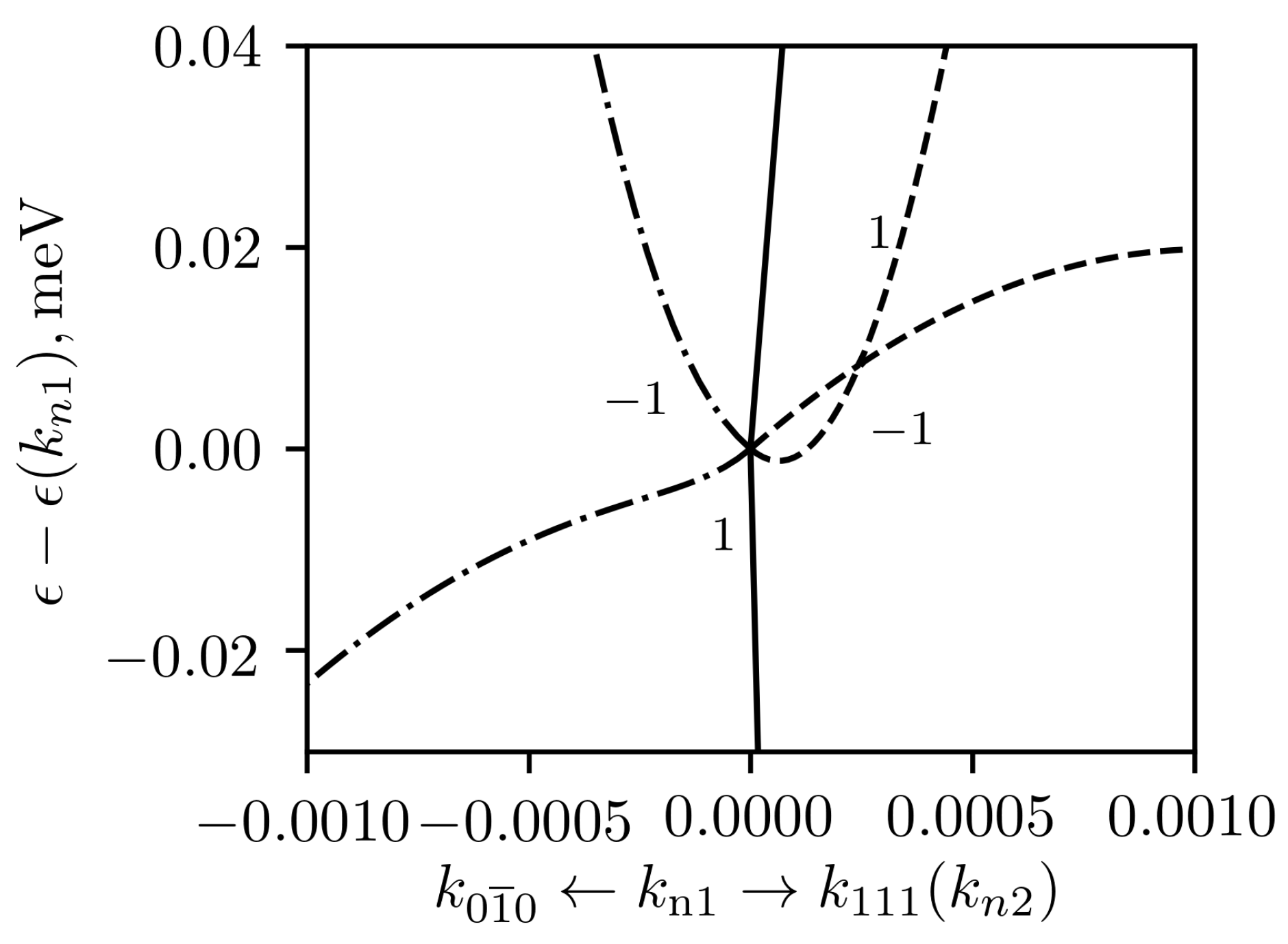
point in unstrained crystal. More detailed calculations showed that there are another 3 nodes in each group: one of them k n 2 is shifted from k n 1 into [ 11 2 ¯ ] direction and positions of two other nodes k n 3 ( 4 ) can be obtained using 2 π / 3 rotation around [111] axis. The distance between nodes is rather small, about 0.0003 at e = 0.01 . The calculation of topological charge showed that three equivalent nodes k n 2 ( 3 , 4 ) have topological charge of 1 each, and the node k n 1 has a charge of −1. Thus total topological charge of each group is 2, giving 4 for both groups together. The dispersion around the nodes is rather complex and is given in the Figure 12. It can be seen that the electronic velocities are very different in different directions, and the nodes are tilted. In addition to these groups of nodes, there are also two tilted Weyl nodes in the directions [111] and [ 1 ¯ 1 ¯ 1 ¯ ] . The lowest band crossing in Figure 11 is one of these node.
Let us now consider the effect of deformation on the low-energy spectrum around the R point in the presence of spin-orbit coupling. In unstrained crystal, the 8-fold degenerate level at the R point splits into 6-fold degenerate level R ¯ 7 + R ¯ 7 (double spin-1 quasiparticles) and doublet R ¯ 5 + R ¯ 6 due to SOC. The doublet is not split by the strain, so we will consider only 6-fold degenerate level (see the Figure 1c). In the case of [100] deformation, it is split into 3 doublets with the wave functions, transforming according to the representations R ¯ 2 + R ¯ 2 , R ¯ 3 + R ¯ 3 and R ¯ 4 + R ¯ 4 of the P 2 1 2 1 2 1 (#19) group. The change of the dispersion around the R point is shown in the Figure 13. Two nodes at lower energy are shifted along positive and negative k x ( k z ) directions under compressive (tensile) strain. There is a crossing of four energy branches at each of these nodal points. They are a tilted double spin-1/2 nodes [33] with Chern numbers of 2 . In the case of eight-band Hamiltonian, the equality ϵ ( k , ϵ ^ ) = ϵ ( k , ϵ ^ ) does not hold exactly. But in the case of [100] deformation the spectrum for six considered bands approximately follows this rule. This implies that there are the two additional double spin-1/2 nodes in k z ( k x ) directions for compressive (tensile) strain (see Figure 13).
The deformation in [110] direction again leads to the splitting of 6-fold degenerate level into 3 doublets at the vertex of deformed Brillouin zone (E point). Wave functions of two doublets are transformed according to the E ¯ 3 + E ¯ 3 representation and one doublet according to the E ¯ 4 + E ¯ 4 representation, where both E ¯ 3 ( 4 ) are real one-dimensional. These doublets do not form Weyl nodes, as the energy branches, starting from them are degenerate at the edges of the Brillouin zone parallel to (001) plane. Four simple Weyl nodes are formed near the E point. They shifted mainly into k z direction to the points with coordinates ± k n , where k n = ( ± 0.001 , 0.001 , 0.014 ) at e = 0.01 (see Figure 14). In the case of tensile strain the shift appeared to be almost the same. As the degeneracy of the bands is completely lifted under this deformation, the topological charge of each of the 4 nodes is 1 .
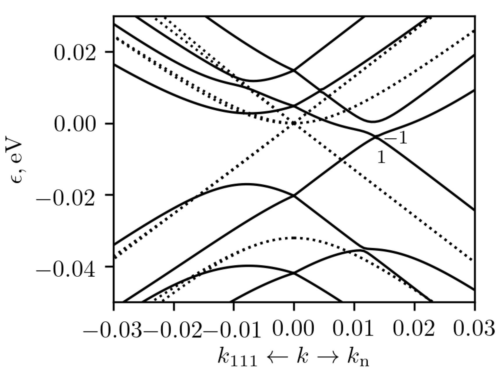
The case of [111] deformation is similar to the two previously considered cases in the sense that one obtains 3 doublets instead of 6-fold degenerate level at the vertex of the Brillouin zone (2 R ¯ 7 ( T ¯ 4 + T ¯ 4 ) + 2 ( T ¯ 5 + T ¯ 6 ) , where T ¯ 4 is real one-dimensional representations, T ¯ 5 and T ¯ 6 , are complex conjugated one dimensional representations of the little group of the T point of the R 3 ( # 146 ) space group). Each of these doublets corresponds to a Weyl node. The two band crossings at the T point are the conventional Weyl nodes with Chern number of 1 . The third band crossing looks like the triple-Weyl node with the topological charge of 3 . It is similar to triple-Weyl node at the Γ point. In addition, near the T point, there are two groups of nodes connected by time-reversal symmetry, as in the case of the Γ point. Two of them are simple Weyl nodes shifted into [111] and [ 1 ¯ 1 ¯ 1 ¯ ] directions, but they have topological charge 1. Around each of them, there are three conventional Weyl nodes with topological charges −1. The total charge of these eight nodes is −4. For example, in the case of compressive strain with e = 0.01 , one of the nodes at the [111] direction have coordinates k n 1 = ( 0.00197 , 0.00197 , 0.00197 ) relative to the T point. One of its satellites have coordinates k n 2 = ( 0.00169 , 0.00196 , 0.00227 ) , and the coordinates of another two satellites k n 3 ( 4 ) can be obtained by cyclic permutations. The dispersion around the T point towards nodes k n 1 and k n 2 is plotted in the Figure 15. It is almost linear. At the same time, the dispersion along the line connecting the central node with one of its satellites (Figure 16) looks like a result of the crossing of two nonlinear bands.

5. Conclusions

In the present work the influence of deformation on the band structure and topological properties of CoSi was studied using both ab initio calculations, and symmetry considerations. The symmetry prescribed k · p Hamiltonians at the Γ and R TRIM points taking into account deformation were written down for the cases with and without SOC. It was shown that in almost all considered cases, the degeneracy is partially lifted at the TRIM points. The only exception is the fourfold degenerate level at the R point (without SOC) under [100] strain. A lowering in symmetry leads to the appearance of a significant number of different band crossings with topological charges from ± 1 to ± 3 around the TRIM points. The nodes often have a tilted dispersion.
The unusual results were obtained upon deformation of CoSi along the [111] direction. Without spin-orbit coupling, the doubly degenerate nodes with quadratic dispersion in the plane orthogonal to the [111] direction appear at the Γ and T points of the deformed Brillouin zone. These band crossings have Chern numbers of ± 2 and resemble the well-known double-Weyl nodes, but they are spin degenerate. Calculation with account of SOC revealed doubly degenerate nodes with the topological charges of ± 3 at the TRIM points. These band crossings are located on the threefold rotation axis and are analogous to triple-Weyl nodes.
The band structure with SOC around the R point under [100] strain exhibits another example of the change of node type. The double spin-1 node with topological charge of 4 splits into pairs of double spin-1/2 nodes with topological charges of 2 per node. Thus, using mechanical deformation, the transition between different types of topological nodes can be realized in the same material.
A lowering of the crystal symmetry under strain also leads to a modification of the surface Fermi arcs shape. A change in the sign of the deformation and the Fermi level position switches the ends of the Fermi arcs from one group of nodes to another. However, the number of Fermi arcs always remains equal to two without taking into account SOC and four with SOC.
As a byproduct of low-energy Hamiltonian fitting, the absolute deformation potential parameters were obtained for considered energy states, and the work function of CoSi was calculated (4.55 eV), which correlates with available experimental data.

Author Contributions

Conceptualization, Y.I. and A.B.; methodology, Y.I.; investigation, S.N. and D.P.-S.; writing—original draft preparation, S.N. and D.P.-S.; writing—review and editing, Y.I. and A.B.; supervision, A.B. All authors have read and agreed to the published version of the manuscript.

Funding

The study was supported by the Russian Foundation for basic Reseach, project 18-52-80005 (BRICS).

Conflicts of Interest

The authors declare no conflict of interest.

Appendix A. k·p Hamiltonians and Their Parameters

In this section, the form of k · p Hamiltonians and their parameters will be given. We used eV units for energy, and the dimensionless wave vector components k i , i = 1 , 2 , 3 are measured in fractions of the reciprocal lattice vectors.
Without spin-orbital coupling linear in wave vector part of Hamiltonian at the Γ point is given by the following equation:
H Γ 1 = 0 i v k 3 i v k 2 i v k 3 0 i v k 1 i v k 2 i v k 1 0 ,
where v = 1.73 eV. The node at the Γ point lies 3.6 meV above the Fermi level.
The perturbation Hamiltonian in the linear approximation in the deformation tensor ϵ i k and in the zero approximation in the wave vector has the following form:
H Γ 2 = S 1 ( ϵ ^ ) D 4 ϵ 12 D 4 ϵ 13 D 4 ϵ 12 S 2 ( ϵ ^ ) D 4 ϵ 23 D 4 ϵ 13 D 4 ϵ 23 S 3 ( ϵ ^ ) ,
where S 1 ( ϵ ^ ) = D 1 ϵ 11 + D 2 ϵ 22 + D 3 ϵ 33 , S 2 ( ϵ ^ ) = D 3 ϵ 11 + D 1 ϵ 22 + D 2 ϵ 33 , S 3 ( ϵ ^ ) = D 2 ϵ 11 + D 3 ϵ 22 + D 1 ϵ 33 , D 1 = −0.319 eV, D 2 = −0.400 eV, D 3 = 0.470 eV and D 4 = 2.479 eV.
At the R point the Hamiltonian, linear in k-vector, was given in Ref. [16]. It can be represented as H R 1 = v 1 ^ ( σ · k ) with v = 1.28 eV. The node at the R point lies 0.211 eV below the Fermi level. The perturbation due to elastic strain reads:
H R 2 = D 1 Tr ϵ ^ D 2 ϵ 12 D 2 ( ϵ 23 i ϵ 13 ) i D 3 ϵ 12 D 3 ( ν 6 * ϵ 23 + i ν 6 ϵ 13 ) D 2 ( ϵ 23 + i ϵ 13 ) D 1 Tr ϵ ^ + D 2 ϵ 12 D 3 ( ν 6 * ϵ 23 i ν 6 ϵ 13 ) i D 3 ϵ 12 i D 3 * ϵ 12 D 3 * ( ν 6 ϵ 23 + i ν 6 * ϵ 13 ) D 1 Tr ϵ ^ + D 2 ϵ 12 D 2 ( ϵ 23 i ϵ 13 ) D 3 * ( ν 6 ϵ 23 i ν 6 * ϵ 13 ) i D 3 * ϵ 12 D 2 ( ϵ 23 + i ϵ 13 ) D 1 Tr ϵ ^ D 2 ϵ 12 ,
where Tr ϵ ^ is a trace of strain tensor, ν 6 = e i π / 6 , D 1 = 0.264 eV, D 2 = −1.29 eV and D 3 = 3.27 eV.
Taking into account spin-orbit coupling, linear Hamiltonian at the Γ point was written down in Ref. [8] and has the following form:
H Γ 1 ( S O C ) = a k 3 a ( k 1 i k 2 ) b ( ν 3 k 1 ν 6 k 2 ) b k 3 a ( k 1 + i k 2 ) a k 3 b k 3 b ( ν 3 k 1 + ν 6 k 2 ) b * ( ν 3 * k 1 ν 6 * k 2 ) b * k 3 a k 3 a ( k 1 + i k 2 ) b * k 3 b * ( ν 3 * k 1 + ν 6 * k 2 ) a ( k 1 i k 2 ) a k 3 ,
where ν 3 = e i π / 3 , a = 0.56 eV and b = 1.19 eV [8]. The 4-fold degenerate node position is 21 meV above the Fermi level, and the Weyl cone at the Γ point is shifted down due to SOC by 54 meV relative to this node.
The perturbation due to deformation reads:
H Γ 2 ( S O C ) = D 1 Tr ϵ ^ + D 2 ϵ 12 D 2 ( ϵ 23 i ϵ 13 ) 0 D 3 Σ ( ϵ ^ ) D 2 ( ϵ 23 + i ϵ 13 ) D 1 Tr ϵ ^ D 2 ϵ 12 D 3 Σ ( ϵ ^ ) 0 0 D 3 * Σ * ( ϵ ^ ) D 1 Tr ϵ ^ + D 2 ϵ 12 D 2 ( ϵ 23 + i ϵ 13 ) D 3 * Σ * ( ϵ ^ ) 0 D 2 ( ϵ 23 i ϵ 13 ) D 1 Tr ϵ ^ D 2 ϵ 12 ,
where Σ ( ϵ ^ ) = ϵ 11 ν 3 ϵ 22 + ν 3 2 ϵ 33 , D 1 = −0.085 eV, D 2 = 1.40 eV. Parameter D 3 is complex. Eigenvalues at k = 0 does not depend on its phase, but it affects the spectrum for nonzero k values. The fitting gives D 3 0.233 e i π / 6 eV.
At the R point the Hamiltonian for 6-fold degenerate node including SOC was given in Ref. [17]. After uniaxial deformation this node splits into three doubly-degenerate nodes. Under deformation in [100] direction, the shift of energy levels at the R point is linear in deformation. If the deformation is applied in [111] direction, only for small e < 0.004 , the shift of energy levels can be considered as linear, and the deformation along [110] axis leads to nonlinear shift of the two pairs of energy levels (see Figure A1). It was shown in Ref. [16] in the framework of a simple model that a linear Hamiltonian that includes SOC in the zeroth order with respect to the wave vector and takes into account all eight bands leads to the correct nonlinear band dispersion near the R point (see, e.g., Figure 3b–c in Ref. [8]). So, we consider both nodes together and obtain 8 × 8 Hamiltonian at the R point. The zero-order Hamiltonian has only nonzero matrix elements ( H R 0 ( S O C ) ) i i = Δ , i = 7 , 8 , which describe energy shift of doublet downwards in energy due to SOC. Including SOC, the position of the 6-fold degenerate node is 0.202 eV below ϵ F , while the band splitting Δ = 32 meV. The zero- and linear-order in k parts together reads:
H R 01 ( S O C ) = 0 a 1 k 3 a 1 * k 2 0 a 2 k 3 a 2 k 2 a 3 k 1 a 4 k 1 a 1 * k 3 0 a 1 k 1 a 2 k 3 0 a 2 k 1 ν 3 a 3 k 2 ν 3 * a 4 k 2 a 1 k 2 a 1 * k 1 0 a 2 k 2 a 2 k 1 0 ν 3 * a 3 k 3 ν 3 a 4 k 3 0 a 2 * k 3 a 2 * k 2 0 a 1 * k 3 a 1 k 2 a 4 * k 1 a 3 * k 1 a 2 * k 3 0 a 2 * k 1 a 1 k 3 0 a 1 * k 1 ν 3 a 4 * k 2 ν 3 * a 3 * k 2 a 2 * k 2 a 2 * k 1 0 a 1 * k 2 a 1 k 1 0 ν 3 * a 4 * k 3 ν 3 a 3 * k 3 a 3 * k 1 ν 3 * a 3 * k 2 ν 3 a 3 * k 3 a 4 k 1 ν 3 * a 4 k 2 ν 3 a 4 k 3 Δ 0 a 4 * k 1 ν 3 a 4 * k 2 ν 3 * a 4 * k 3 a 3 k 1 ν 3 a 3 k y ν 3 * a 3 k 3 0 Δ ,
where parameters a i are complex. Their values were obtained by fitting to electron spectrum around R point. They are not unique, but they were checked to give correct values of topological charges. These values are a 1 = ( 0.342 0.686 i ) eV, a 2 = ( 1.043 + 0.060 i ) eV, a 3 = ( 0.459 0.657 i ) eV and a 4 = ( 0.181 0.100 i ) eV.
Figure A1. The splitting of energy levels at the R point with uniaxial stress of magnitude e in [110] (left panel) and in [111] (right panel) directions.
Crystals 11 00143 g0a1
The perturbation due to deformation is:
H R 2 ( S O C ) = S 1 ( ϵ ^ ) D 5 ϵ 12 D 5 * ϵ 13 0 D 6 ϵ 12 D 6 ϵ 13 D 7 ϵ 23 D 8 ϵ 23 D 5 * ϵ 12 S 2 ( ϵ ^ ) D 5 ϵ 23 D 6 ϵ 12 0 D 6 ϵ 23 D 7 ϵ 13 ν 3 D 8 ϵ 13 ν 3 * D 5 ϵ 13 D 5 * ϵ 23 S 3 ( ϵ ^ ) D 6 ϵ 13 D 6 ϵ 23 0 D 7 ϵ 12 ν 3 * D 8 ϵ 12 ν 3 0 D 6 * ϵ 12 D 6 * ϵ 13 S 1 ( ϵ ^ ) D 5 * ϵ 12 D 5 ϵ 13 D 8 * ϵ 23 D 7 * ϵ 23 D 6 * ϵ 12 0 D 6 * ϵ 23 D 5 ϵ 12 S 2 ( ϵ ^ ) D 5 * ϵ 23 D 8 * ϵ 13 ν 3 D 7 * ϵ 13 ν 3 * D 6 * ϵ 13 D 6 * ϵ 23 0 D 5 * ϵ 13 D 5 ϵ 23 S 3 ( ϵ ^ ) D 8 * ϵ 12 ν 3 * D 7 * ϵ 12 ν 3 D 7 * ϵ 23 D 7 * ϵ 13 ν 3 * D 7 * ϵ 12 ν 3 D 8 ϵ 23 D 8 ϵ 13 ν 3 * D 8 ϵ 12 ν 3 D 4 Tr ϵ ^ 0 D 8 * ϵ 23 D 8 * ϵ 13 ν 3 D 8 * ϵ 12 ν 3 * D 7 ϵ 23 D 7 ϵ 13 ν 3 D 7 ϵ 12 ν 3 * 0 D 4 Tr ϵ ^ ,
where D 1 = 0.318 eV, D 2 = 0.211 eV, D 3 = 0.261 eV, D 4 = 0.270 eV are real and determine the shift of each pair of energy levels under [100] deformation. The splitting of levels under the compressive or tensile strain e in [110] direction also can be obtained analytically. Two doublets linearly shift with deformation e
ϵ R = 2 D 1 + D 2 + D 3 ± ( D 2 D 3 ) 2 + 4 ( | D 5 | 2 + | D 6 | 2 ) e / 4 ,
from which | D 5 | 2 + | D 6 | 2 = 3.5 eV can be obtained. But another four levels shift nonlinearly
ϵ R = ( D 2 + D 3 + 2 D 4 ) e 2 Δ ± ( ( D 2 + D 3 2 D 4 ) e + 2 Δ ) 2 + 4 e 2 ( | D 7 | 2 + | D 8 | 2 ) / 4 .
| D 7 | 2 + | D 8 | 2 = 3.36 eV. Other parameters were obtained from fitting to band structures of deformed crystal. They are non-unique, one of possible parameter sets is D 5 = ( 1.107 2.916 i ) eV, D 6 = ( 0.713 + 1.420 i ) eV, D 7 = ( 1.147 + 1.048 i ) eV, D 8 = ( 1.667 + 2.469 i ) eV.

Appendix B. Absolute Deformation Potentials and Work Function of CoSi

In order to obtain absolute shift of energy level ϵ n after deformation, it is necessary to have common reference energy in deformed and undeformed crystals or to determine the shift of the reference due to deformation. For example, energy can be measured from macroscopic average of effective self-consistent potential V e . Then absolute shift of energy level ϵ n due to deformation is equal to Δ ϵ n = ( ϵ n ( d ) V e ( d ) ) ( ϵ n ( u ) V e ( u ) ) + Δ V e , where Δ V e is the reference energy offset due to strain and superscript d(u) corresponds to bulk calculation for deformed (undeformed) crystal.
The vacuum level can be used as a common reference energy, but it is not accessible in bulk DFT calculation. Hence we apply approach similar to that used for work function calculations. The superlattice configuration was considered with alternating layers of material and vacuum gaps. Average effective potential inside material layer V e was calculated relative to its value inside vacuum gap (vacuum energy level). Then, the change of average effective potential Δ V e due to deformation can be calculated as a deference between the values obtained from separate calculations for strained and unstrained layers.
Alternative approach was used in Ref. [39], where another superlattice method was proposed in order to obtain reference energy offset. The superlattice was formed from layers, extended or compressed along the direction of superlattice axis, and the layers were undeformed in the plane. In all-electron calculations, performed in Ref. [39], localized core levels, used as an energy reference, can be associated with each of the layers. The difference in their energy positions in the limit of thick layers allowed to obtain the reference energy offset due to deformation. Similar approach was used in Ref. [40], where pseudopotential calculations were used and, instead of core levels, macroscopic average effective potential in deformed V e ( D L ) and undeformed V e ( U L ) layers was used to determine the change of the energy reference due to deformation Δ V e = V e ( D L ) V e ( U L ) . We also used the latter approach and made similar calculations for superlattice of strained/unstrained layers of CoSi for [100], [110] and [111] directions. We checked the convergence of Δ V e with respect to the layer thickness. The accuracy of 1–2 meV was reached for the layer thickness of 10 a 0 .
Inside thick metallic layers, thicker then screening length, the difference ( V e ϵ F ) is determined only by its bulk properties, and the superlattice made of strained/unstrained layers should have common Fermi level ϵ F . Hence, the same Δ V e can be obtained from bulk calculations for deformed and undeformed crystal Δ V e = ( V e ( d ) ϵ F ( d ) ) ( V e ( u ) ϵ F ( u ) ) . Then, the absolute shift of energy level ϵ n due to deformation can be calculated as Δ ϵ n = ( ϵ n ( d ) ϵ F ( d ) ) ( ϵ n ( u ) ϵ F ( u ) ) .
All three considered approaches should give the same results for metallic material. Although CoSi is considered as semimetallic, the comparison gave the same results for Δ V e to within 1–2 meV. In addition, we obtained work function for CoSi, equal to 4.55 eV which compares favourably with experimental values of 4.47–4.54 eV [41].

References

  1. Asanabe, S.; Shinoda, D.; Sasaki, Y. Semimetallic Properties of Co1−xFexSi Solid Solutions. Phys. Rev. 1964, 134, A774. [Google Scholar] [CrossRef]
  2. Fedorov, M.I.; Zaitsev, V.K. Semimetals as materials for thermoelectric generators. In CRC Handbook of Thermoelectrics; Rowe, D.M., Ed.; CRC Press: Boca Raton, FL, USA, 1995; Chapter 27. [Google Scholar]
  3. Pan, Z.; Zhang, L.; Wu, J. Electronic structure and transport properties of doped CoSi single crystal. J. Appl. Phys. 2007, 101, 033715. [Google Scholar] [CrossRef]
  4. Sakai, A.; Ishii, F.; Onose, Y.; Tomioka, Y.; Yotsuhashi, S.; Adachi, H.; Nagaosa, N.; Tokura, Y. Thermoelectric power in transition-metal monosilicides. J. Phys. Soc. Jpn. 2007, 76, 093601. [Google Scholar] [CrossRef]
  5. Ishii, F.; Kotaka, H.; Onishi, T. Spin–Orbit Interaction Effects in the Electronic Structure of B20-Type CoSi: First-Principles Density Functional Study. JPS Conf. Proc. 2014, 3, 016019. [Google Scholar] [CrossRef] [Green Version]
  6. Tang, P.; Zhou, Q.; Zhang, S.C. Multiple Types of Topological Fermions in Transition Metal Silicides. Phys. Rev. Lett. 2017, 119, 206402. [Google Scholar] [CrossRef] [Green Version]
  7. Chang, G.; Xu, S.Y.; Wieder, B.J.; Sanchez, D.S.; Huang, S.M.; Belopolski, I.; Chang, T.R.; Zhang, S.; Bansil, A.; Lin, H.; et al. Unconventional Chiral Fermions and Large Topological Fermi Arcs in RhSi. Phys. Rev. Lett. 2017, 119, 206401. [Google Scholar] [CrossRef] [Green Version]
  8. Pshenay-Severin, D.A.; Ivanov, Y.V.; Burkov, A.A.; Burkov, A.T. Band structure and unconventional electronic topology of CoSi. J. Phys. Condens. Matter 2018, 30, 135501. [Google Scholar] [CrossRef] [Green Version]
  9. Yu, J.; Kuang, J.; Long, J.; Ke, X.; Duan, X.; Liu, Z. Effects of nonstoichiometry on thermoelectric properties of CoSi-based materials. J. Mater. Sci. Mater. Electron. 2020, 31, 2139–2144. [Google Scholar] [CrossRef]
  10. Pshenay-Severin, D.A.; Ivanov, Y.V.; Burkov, A.T.; Novikov, S.V.; Zaitsev, V.K.; Reith, H. Electronic Structure and Thermoelectric Properties of Transition Metal Monosilicides. J. Electron. Mater. 2018, 47, 3277–3281. [Google Scholar] [CrossRef]
  11. Pshenay-Severin, D.A.; Ivanov, Y.V.; Burkov, A.T. The effect of energy-dependent electron scattering on thermoelectric transport in novel topological semimetal CoSi. J. Phys. Condens. Matter 2018, 30, 475501. [Google Scholar] [CrossRef] [Green Version]
  12. Antonov, A.; Ivanov, Y.; Konstantinov, P.; Kuznetsova, V.; Novikov, S.; Ovchinnikov, A.; Pshenay-Severin, D.; Burkov, A. Thermoelectric and galvanomagnetic properties of topologically non-trivial (Co-M)Si semimetals (M = Fe, Ni) at high temperatures. J. Appl. Phys. 2019, 126, 245103. [Google Scholar] [CrossRef]
  13. Xu, X.; Wang, X.; Cochran, T.A.; Sanchez, D.S.; Chang, G.; Belopolski, I.; Wang, G.; Liu, Y.; Tien, H.J.; Gui, X.; et al. Crystal growth and quantum oscillations in the topological chiral semimetal CoSi. Phys. Rev. B 2019, 100, 045104. [Google Scholar] [CrossRef] [Green Version]
  14. Balasubramanian, B.; Manchanda, P.; Pahari, R.; Chen, Z.; Zhang, W.; Valloppilly, S.R.; Li, X.; Sarella, A.; Yue, L.; Ullah, A.; et al. Chiral Magnetism and High-Temperature Skyrmions in B20-Ordered Co-Si. Phys. Rev. Lett. 2020, 124, 057201. [Google Scholar] [CrossRef] [PubMed] [Green Version]
  15. Xu, B.; Fang, Z.; Sanchez-Martinez, M.A.; Venderbos, J.W.F.; Ni, Z.; Qiu, T.; Manna, K.; Wang, K.; Paglione, J.; Bernhard, C.; et al. Optical signatures of multifold fermions in the chiral topological semimetal CoSi. Proc. Natl. Acad. Sci. USA 2020, 117, 27104–27110. [Google Scholar] [CrossRef]
  16. Manes, J.L. Existence of bulk chiral fermions and crystal symmetry. Phys. Rev. B 2012, 85, 155118. [Google Scholar] [CrossRef] [Green Version]
  17. Bradlyn, B.; Cano, J.; Wang, Z.; Vergniory, M.G.; Felser, C.; Cava, R.J.; Bernevig, B.A. Beyond Dirac and Weyl fermions: Unconventional quasiparticles in conventional crystals. Science 2016, 353, aaf5037. [Google Scholar] [CrossRef] [Green Version]
  18. Sanchez, D.S.; Belopolski, I.; Cochran, T.A.; Xu, X.; Yin, J.X.; Chang, G.; Xie, W.; Manna, K.; Süß, V.; Huang, C.Y.; et al. Topological chiral crystals with helicoid-arc quantum states. Nature 2019, 567, 500–505. [Google Scholar] [CrossRef]
  19. Takane, D.; Wang, Z.; Souma, S.; Nakayama, K.; Nakamura, T.; Oinuma, H.; Nakata, Y.; Iwasawa, H.; Cacho, C.; Kim, T.; et al. Observation of Chiral Fermions with a Large Topological Charge and Associated Fermi-Arc Surface States in CoSi. Phys. Rev. Lett. 2019, 122, 076402. [Google Scholar] [CrossRef] [Green Version]
  20. Rao, Z.; Li, H.; Zhang, T.; Tian, S.; Li, C.; Fu, B.; Tang, C.; Wang, L.; Li, Z.; Fan, W.; et al. Observation of unconventional chiral fermions with long Fermi arcs in CoSi. Nature 2019, 567, 496–499. [Google Scholar] [CrossRef] [Green Version]
  21. Dutta, P.; Pandey, S.K. Effects of correlations and temperature on the electronic structures and related physical properties of FeSi and CoSi: A comprehensive study. J. Phys. Condens. Matter 2019, 31, 145602. [Google Scholar] [CrossRef]
  22. Pshenay-Severin, D.A.; Burkov, A.T. Electronic Structure of B20 (FeSi-Type) Transition-Metal Monosilicides. Materials 2019, 12, 2710. [Google Scholar] [CrossRef] [PubMed] [Green Version]
  23. Schnatmann, L.; Geishendorf, K.; Lammel, M.; Damm, C.; Novikov, S.; Thomas, A.; Burkov, A.; Reith, H.; Nielsch, K.; Schierning, G. Signatures of a Charge Density Wave Phase and the Chiral Anomaly in the Fermionic Material Cobalt Monosilicide CoSi. Adv. Electron. Mater. 2020, 6, 1900857. [Google Scholar] [CrossRef]
  24. Krishna Nichenametla, C.; Calvo, J.; Riedel, S.; Gerlich, L.; Hindenberg, M.; Novikov, S.; Burkov, A.; Kozelj, P.; Cardoso-Gil, R.; Wagner-Reetz, M. Doping Effects in CMOS-compatible CoSi Thin Films for Thermoelectric and Sensor Applications. Z. Anorg. Allg. Chem. 2020, 646, 1231–1237. [Google Scholar] [CrossRef]
  25. Hernandez, J.; Vočadlo, L.; Wood, I. High pressure stability of the monosilicides of cobalt and the platinum group elements. J. Alloys Compd. 2015, 626, 375–380. [Google Scholar] [CrossRef]
  26. Giannozzi, P.; Baroni, S.; Bonini, N.; Calandra, M.; Car, R.; Cavazzoni, C.; Ceresoli, D.; Chiarotti, G.L.; Cococcioni, M.; Dabo, I.; et al. QUANTUM ESPRESSO: A modular and open-source software project for quantum simulations of materials. J. Phys. Condens. Matter 2009, 21, 395502. [Google Scholar] [CrossRef]
  27. Hamann, D.R. Optimized norm-conserving Vanderbilt pseudopotentials. Phys. Rev. B 2013, 88, 085117. [Google Scholar] [CrossRef] [Green Version]
  28. Mostofi, A.A.; Yates, J.R.; Pizzi, G.; Lee, Y.S.; Souza, I.; Vanderbilt, D.; Marzari, N. An updated version of wannier90: A tool for obtaining maximally-localised Wannier functions. Comput. Phys. Commun. 2014, 185, 2309. [Google Scholar] [CrossRef] [Green Version]
  29. Wu, Q.; Zhang, S.; Song, H.F.; Troyer, M.; Soluyanov, A.A. WannierTools: An open-source software package for novel topological materials. Comput. Phys. Commun. 2018, 224, 405. [Google Scholar] [CrossRef] [Green Version]
  30. Bir, G.L.; Pikus, G.E. Symmetry and Strain-Induced Effects in Semiconductors; Wiley: New York, NY, USA, 1974. [Google Scholar]
  31. Voon, L.C.L.Y. Electronic and Optical Properties of Semiconductors: A Study Based on the Empirical Tight Binding Model; Universal-Publishers: Parkland, FL, USA, 1997. [Google Scholar]
  32. Elcoro, L.; Bradlyn, B.; Wang, Z.; Vergniory, M.G.; Cano, J.; Felser, C.; Bernevig, B.A.; Orobengoa, D.; Flor, G.; Aroyo, M.I. Double crystallographic groups and their representations on the Bilbao Crystallographic Server. J. Appl. Crystallogr. 2017, 50, 1457–1477. [Google Scholar] [CrossRef]
  33. Flicker, F.; de Juan, F.; Bradlyn, B.; Morimoto, T.; Vergniory, M.G.; Grushin, A.G. Chiral optical response of multifold fermions. Phys. Rev. B 2018, 98, 155145. [Google Scholar] [CrossRef] [Green Version]
  34. Soluyanov, A.A.; Gresch, D.; Wang, Z.; Wu, Q.; Troyer, M.; Dai, X.; Bernevig, B.A. Type-II Weyl semimetals. Nature 2015, 527, 495–498. [Google Scholar] [CrossRef] [PubMed] [Green Version]
  35. Huang, S.M.; Xu, S.Y.; Belopolski, I.; Lee, C.C.; Chang, G.; Chang, T.R.; Wang, B.; Alidoust, N.; Bian, G.; Neupane, M.; et al. New type of Weyl semimetal with quadratic double Weyl fermions. Proc. Natl. Acad. Sci. USA 2016, 113, 1180. [Google Scholar] [CrossRef] [PubMed] [Green Version]
  36. Fang, C.; Gilbert, M.J.; Dai, X.; Bernevig, B.A. Multi-Weyl Topological Semimetals Stabilized by Point Group Symmetry. Phys. Rev. Lett. 2012, 108, 266802. [Google Scholar] [CrossRef]
  37. Tsirkin, S.S.; Souza, I.; Vanderbilt, D. Composite Weyl nodes stabilized by screw symmetry with and without time-reversal invariance. Phys. Rev. B 2017, 96, 045102. [Google Scholar] [CrossRef] [Green Version]
  38. Chang, G.; Wieder, B.J.; Schindler, F.; Sanchez, D.S.; Belopolski, I.; Huang, S.M.; Singh, B.; Wu, D.; Chang, T.R.; Neupert, T.; et al. Topological quantum properties of chiral crystals. Nat. Mater. 2018, 17, 978–985. [Google Scholar] [CrossRef] [PubMed]
  39. Franceschetti, A.; Wei, S.H.; Zunger, A. Absolute deformation potentials of Al, Si, and NaCl. Phys. Rev. B 1994, 50, 17797–17801. [Google Scholar] [CrossRef] [Green Version]
  40. Murphy, A.R.; Murphy-Armando, F.; Fahy, S.; Savić, I. Acoustic deformation potentials of n-type PbTe from first principles. Phys. Rev. B 2018, 98, 085201. [Google Scholar] [CrossRef] [Green Version]
  41. Kedzierski, J.; Nowak, E.; Kanarsky, T.; Zhang, Y.; Boyd, D.; Carruthers, R.; Cabral, C.; Amos, R.; Lavoie, C.; Roy, R.; et al. Metal-gate FinFET and fully-depleted SOI devices using total gate silicidation. In Proceedings of the Digest, International Electron Devices Meeting, San Francisco, CA, USA, 8–11 December 2002; pp. 247–250. [Google Scholar] [CrossRef]
Figure 1. The unit cell (a), the Brillouin zone (b) and the band structure of CoSi, calculated with (c) and without (d) the account of spin-orbit coupling. Insets in (c,d) show band structure around multi-fold band crossings at the Γ and R points (numbers are topological charges).
Crystals 11 00143 g001
Figure 2. The splitting of energy levels around the Γ point under uniaxial strain along [100] direction. Dotted lines represent the spectrum of undeformed crystal, solid (dashed) lines represent the spectrum in the case of compressive (tensile) strain. The absolute value of strain is | e | = 0.01 . The wave vectors are measured in 2 π / a 0 units.
Crystals 11 00143 g002
Figure 3. The details of surface Fermi arcs around the Γ point under uniaxial strain along [100] direction ( e = 0.01 ) without the account of spin-orbit coupling (SOC). Asterisks depict the positions of nodal points.
Crystals 11 00143 g003
Figure 4. The splitting of energy levels around the Γ point under uniaxial stain along [110] direction. Dotted lines represent the spectrum of undeformed crystal, solid (dashed) lines represent the spectrum in the case of compressive (tensile) strain. The absolute value of strain is | e | = 0.01 .
Crystals 11 00143 g004
Figure 5. The splitting of energy levels around the Γ point under uniaxial stain along [111] direction. Dotted lines represent the spectrum of undeformed crystal, solid (dashed) lines represent the spectrum in the case of compressive (tensile) strain. The absolute value of strain is | e | = 0.01 .
Crystals 11 00143 g005
Figure 6. The details of surface Fermi arcs around the Γ point under uniaxial compression (left panel) and extension (right panel) along [111] direction ( | e | = 0.01 ) without the account of SOC. Asterisks depict the position of nodal points.
Crystals 11 00143 g006
Figure 7. The splitting of energy levels around the R point under uniaxial stain along [110] direction (E point, P2 1 space group). Dotted lines represent the spectrum of undeformed crystal, solid lines represent the spectrum in the case of compressive strain. The value of strain is e = 0.01 .
Crystals 11 00143 g007
Figure 8. The splitting of energy levels around the R point under uniaxial stain along [111] direction (T point of R 3 space group). Dotted lines represent the spectrum of undeformed crystal, solid (dashed) lines represent the spectrum in the case of compressive (tensile) strain. The absolute value of strain is | e | = 0.01 .
Crystals 11 00143 g008
Figure 9. The splitting of energy levels around the Γ point under uniaxial stain along [100] direction. Dotted lines represent the spectrum of undeformed crystal, solid lines represent the spectrum in the case of compressive strain with e = 0.01 .
Crystals 11 00143 g009
Figure 10. The details of surface Fermi arcs around the Γ point under uniaxial strain along [100] direction ( e = 0.01 ) with the account of SOC. Asterisks depict the positions of nodal points.
Crystals 11 00143 g010
Figure 11. The splitting of energy levels around the Γ point under uniaxial stain along [111] direction. Dotted lines represent the spectrum of undeformed crystal, solid lines represent the spectrum in the case of compressive strain for e = 0.01 .
Crystals 11 00143 g011
Figure 12. The dispersion around the nodes shifted from the Γ point under uniaxial compressive strain along [111] direction. The dispersions along [111] (solid lines), [1 1 ¯ 0] (dot-dashed lines) and [11 2 ¯ ] (towards the node k n 2 , dashed lines) directions are plotted for e = 0.01 .
Crystals 11 00143 g012
Figure 13. The splitting of energy levels around the R point under uniaxial stain along [100] direction. Dotted lines represent the spectrum of undeformed crystal, solid (dashed) lines represent the spectrum in the case of compressive (tensile) strain of | e | = 0.01 .
Crystals 11 00143 g013
Figure 14. The splitting of energy levels around the R point (E point, P2 1 space group) under uniaxial stain along [110] direction. Dotted lines represent the spectrum of undeformed crystal, solid lines represent the spectrum in the case of compressive strain of e = 0.01 .
Crystals 11 00143 g014
Figure 15. The splitting of energy levels around the R point under uniaxial stain along [111] direction (T point, R 3 space group). Dotted lines represent the spectrum of undeformed crystal, solid lines represent the spectrum in the case of compressive strain of e = 0.01 .
Crystals 11 00143 g015
Figure 16. The electronic dispersion along the direction from central node k n 1 towards to one of its satellites under uniaxial stain along [111] direction at e = 0.01 .
Crystals 11 00143 g016
Publisher’s Note: MDPI stays neutral with regard to jurisdictional claims in published maps and institutional affiliations.

