Abstract
Quantum anomalous Hall effect (QAHE) represents a quantized version of the classical anomalous Hall effect. In the latter case the magnetization takes over the role of magnetic field and induces nonzero off-diagonal elements in the conductivity matrix. In magnetic topological insulators with the band inversion the QAHE can be reached due to quantized conduction channel at the sample edge if the Fermi energy is tuned into the surface magnetic gap. In the static regime the QAHE is seen as a zero-field step in the Hall resistivity. At optical frequencies this step is transformed into a quantized value of the polarization rotation approaching the fine structure constant . However, due to material issues the steps reach the predicted values at millikelvin temperatures only. In this work we investigate the Faraday polarization rotation in thin films of Cr-doped topological insulator and in the sub-terahertz frequency range. Well defined polarization rotation steps can be observed in transmittance in Faraday geometry. At temperatures down to K the value of the rotation reached about 20% of the fine structure constant and disappeared completely for K.
1. Introduction
Topological insulators [1,2] are materials with insulating bulk but revealing conducting surface states. These states possess different helicity thus making them symmetry protected against non-magnetic scattering processes. In two-dimensional (2D) systems and in external magnetic fields the quantized off-diagonal conductivity is observed proportional to an integer times the conductivity quantum . However, the application of external magnetic fields can be avoided in magnetically-doped topological insulators [3], see Refs. [4,5] for reviews. In that case the coupling between magnetic moments of the dopants must be strong enough to obtain a magnetically ordered state with finite static magnetization [6]. In addition, the Fermi level must be shifted into the surface magnetic gap thus leading to a single quantized conducting channel at the edge. QAHE in magnetically-doped topological insulators can be seen as a last station starting from the classical Hall resistivity via time reversal breaking and quantization effects [7].
The predicted QAHE has been first observed [8] in Cr-doped (Bi,Sb)Te and at millikelvin temperatures. In these, as well as in several similar experiments [9,10], the temperature range at that well-quantized conduction states are observed is substantially lower than the transition temperature to a magnetically ordered state of typically 20 K. This discrepancy is normally attributed to the sample issues like presence of additional dissipative channels [4,5]. More recently, QAHE in several magnetic topological insulators [11,12,13] could be achieved at temperatures close to 1 K.
In conducting materials a step in the Hall resistivity should normally lead to a step in optical properties. We note here an existing discrepancy in interpretation of the quantum Hall effect in statics and dynamics of the 2D systems [14]. In the former case the quantization is explained by counting the quantum conducting channels at the edge [2,15]. In the optical case, the edges are normally excluded due to contact-free technique. Therefore, to explain the quantization of the optical data, one have to return to the quantization of the bulk conduction [16,17]. In the dynamic regime, one of the typical observation in two-dimensional systems is the polarization rotation of linearly-polarized light in transmission geometry, see Figure 1.
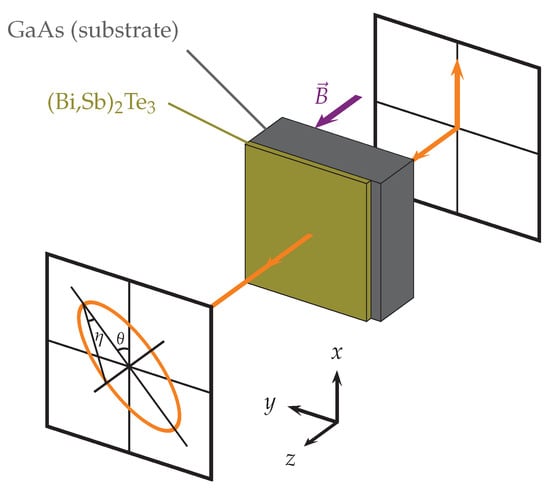
Figure 1.
Scheme of the optical experiment. Linearly polarized incident light is transformed into the elliptical polarization after the sample, and is characterized by Faraday rotation angle and ellipticity . The analyzer in front of the detector projects the ellipse either into the same direction as the incident beam leading to parallel transmittance or to perpendicular direction leading to the crossed transmittance . An external magnetic field is applied parallel to the propagation direction (Faraday geometry).
Full expressions for the polarization rotation include the influence of the substrate and are given elsewhere [18,19,20]. However, two important approximations substantially simplify the interpretation of the data. First, the influence of the substrate can be removed if the field-dependent experiment is done in the maximum of the Fabry-Pérot resonances of the substrate (see Figure 6 ). At such frequencies the expressions for the Faraday rotation reduce to the substrate-free result [18,21]. Second, in most cases the thin film approximation can be used assuming that the influence of the conducting film is small: . Here is the 2D diagonal conductivity, is the 2D Hall conductivity and is the impedance of free space.
In the following we assume that the incident radiation is linearly polarized with the electric field along the x-axis and is propagating along the z-axis. In the thin film approximation the transmittance amplitudes in the parallel and perpendicular channels are given by [18]
respectively. In present experiments, and are measured putting the analyzer parallel and perpendicular to the polarization of the incident beam. The phase shift (or optical thickness) of both signals are obtained using the Mach-Zehnder interferometer arrangement, see Methods Section.
Further on, especially for the samples of the present work, the scattering time of the charge carriers is rather small, thus the frequency dependent terms in conductivities and can be neglected. This can be derived from the fact that we do not observe any signs of the cyclotron resonance in the present range of frequencies and magnetic fields. This indicates that the resonance terms in the Drude conductivity with typical width are negligible. In the same approximation the (Faraday) rotation angle can be written as [18,19,20]:
In the quantum regime we expect only a single conduction channel with leading to
where 7.3 × rad is the fine structure constant.
2. Results and Discussion
Figure 2 shows typical magnetic field dependence of the transmittance in crossed polarizers geometry that is most sensitive to weak polarization rotations. In these experiments the amplitude of the signal corresponds to the transmittance amplitude and the optical thickness is related to the phase shift of the transmittance. The absolute values of the optical thickness are mainly determined by the thickness and refractive index of the substrate (see Section 4). The magnetic field-induced changes can be attributed to the film properties that are basically determined by in this geometry in agreement with Equation (1). The data reveal a clear step at zero magnetic fields with a hysteresis of about 0.09 T. Compared to the data shown in Figure 5 below, the transmittance is not affected by the contact resistivity and, therefore, provides more direct information on the sample conductivity.
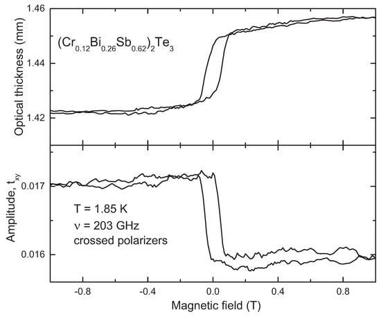
Figure 2.
Magnetic field scans of the transmittance in (CrBiSb)Te film and in crossed polarizers geometry . The external field is applied parallel to the propagation direction (Faraday geometry, see Figure 1). The parameters of the experiment are given in the plot. Bottom panel: amplitude of the crossed signal. Top panel: relative optical thickness (phase shift) of the sample.
After a calibration to absolute values, the complex polarization rotation angle can be calculated either using the simplified Equations (1) and (2) or via the exact procedure [18,19,20].
Complex polarization rotation angles at the lowest temperature of our experiments ( K) and at various frequencies are shown in Figure 3. We observe that in the frequency range of the present experiment the rotation angle is approximately a real number, as the ellipticity corresponds roughly to the noise level of the spectrometer. Similarly to the raw transmittance data in Figure 2, the Faraday rotation angle shows a clear step-like function across zero magnetic field. The inset in Figure 3 shows the absolute values of the rotation angle step at zero magnetic field and as a function of frequency.
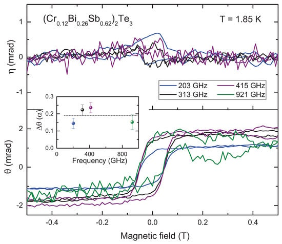
Figure 3.
Complex polarization rotation angle in (CrBiSb)Te at K and at different frequencies. The frequencies were selected at the maxima of the Fabry-Pérot interferences to suppress the effect of the substrate in the spectra. Bottom panel: Faraday rotation angle , top panel: ellipticity . The inset shows the absolute values of the rotation angle due to quantum anomalous Hall effect (QAHE) in the units of the fine structure constant at zero magnetic field and as a function of frequency. Straight dashed line is to guide the eye.
We conclude that in the frequency range of the present experiment the Faraday angle is roughly frequency independent at the value and the variation of the data corresponds to the uncertainties of the experiment. In order to get more arguments on the absolute values of the step across the zero field, we investigated the temperature dependence of the Faraday rotation. These results are shown in Figure 4. As also seen in the frequency-dependent rotation angles, Figure 3, the ellipticity in our data is close to zero within the experimental uncertainties. The Faraday rotation, as shown in the bottom panel and in the inset to Figure 4, decreases with increasing temperature. In our experiments the step disappears around 20 K that agrees reasonably well with Curie temperature estimated [9] as K. The Faraday step at our lowest temperatures is . This value is substantially smaller than expected within simple arguments. However, it is still possible that scattering processes suppressing will freeze out at millikelvin temperatures. We conclude that at temperatures down to 1.85 K additional dissipative channels like residual carriers from bulk bands or scattering by impurities [4,5,22] are still present, which impedes the dissipationless character of the chiral states and suppresses the universally quantized values of the Hall resistance and of the Faraday rotation.
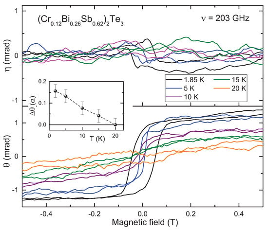
Figure 4.
Complex polarization rotation angle in (CrBiSb)Te at GHz and at different temperatures. Bottom panel: Faraday rotation angle , top panel: ellipticity . The inset shows the absolute values of the step of the rotation angle in the units of the fine structure constant at zero magnetic field and as a function of temperature.
As the transmission experiments are done in the Faraday geometry and the sample is magnetic, the magneto-optical Faraday effect [23] cannot be a priori neglected. In fact, in the small angle approximation, the rotation angles due to the off-diagonal conductivity and due to the static magnetization are simply added. To estimate the value of the last effect, we use Equation (8) of the Methods Section. The value of the static magnetization in our samples T has been measured in Ref. [9]. It agrees well with an estimate assuming fully ordered moments of Cr ions. Putting the numbers into Equation (8) we finally get:
We see that in most cases dealing with QAHE the classical Faraday effect can be neglected.
Finally, we compare the static and dynamic results in our sample. In agreement with Equations (1) and (2) direct correspondence between both properties may be expected. As discussed in the Methods Section, the resistivity of indium contacts was too high thus distorting the magnetic field dependencies of the diagonal and Hall resistivity. Reasonable step-like Hall resistivity data could be obtained for K only, see Figure 5. Although the Hall data were distorted, we still could estimate the steps across zero field (inset to Figure 5) and compare them with the dynamic data in Figure 3 and Figure 4. We see that both steps disappear at temperatures close to 20 K. The absolute values of the Hall resistivity in Figure 5 correspond to in our lowest temperature of 1.85 K that deviates from the values of Faraday rotation ∼0.2 observed in the transmittance data. We recall, however, that the resistivity was strongly affected by highly resistive contacts, although the rotation is measured by a contact-free technique.
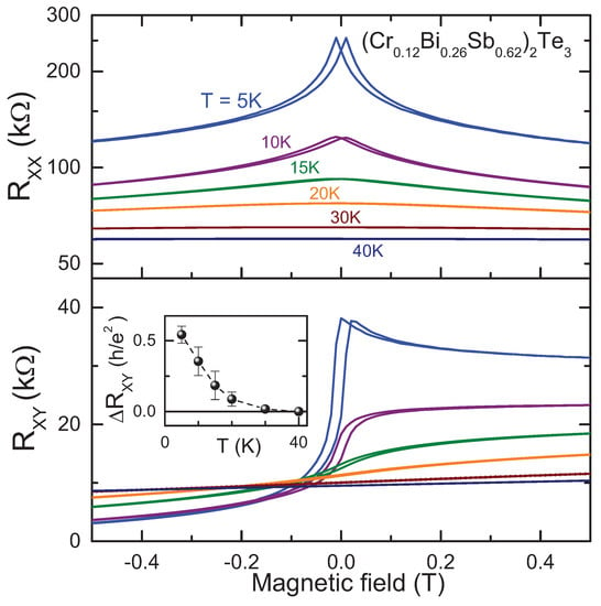
Figure 5.
Magnetoresistance data in (CrBiSb)Te film at various temperatures. Top: diagonal resistivity; bottom: Hall resistivity. The inset shows the absolute values of the step in the Hall resistance at zero magnetic field and as a function of temperature.
3. Conclusions
In this work we investigated the polarization rotation of the sub-terahertz light in thin films of Cr-doped topological insulator (CrBiSb)Te. The optical data are compared to the step in the quantum Hall conductivity measured by static technique. Well defined polarization rotation steps can be observed in transmittance at different frequencies and temperatures. At the lowest temperature of K the value of the rotation angle reached about 20% of the fine structure constant and disappeared completely for K. We estimate that pure magnetic contribution to the Faraday rotation can be neglected in the present case.
4. Materials and Methods
Single-crystalline (CrBiSb)Te films on insulating (111) GaAs substrates were grown by molecular beam epitaxy [9,10,24]. Both the Cr doping level (12%) and the (Bi/Sb) ratio (0.3/0.7) were optimized so that the Fermi level positions of the as-grown samples were close to the charge neutrality point. The growth was monitored by reflection high-energy electron diffraction and the films with a thickness of 6 quintuple layers (∼6 nm) were obtained. After the film growth, a 2 nm Al was evaporated to passivate the films. During the growth procedure the back side of the sample was fully covered with indium film that was nontransparent for the terahertz radiation. Therefore, prior to the optical experiments this film was removed by polishing. To measure the static resistivity, indium contacts were made at the corners of the hexagon-like sample at soldering temperature of 560 K. Unfortunately, this procedure did not provide good contacts, thus reasonable static Hall resistivity could be measured at K only (see Figure 5).
Terahertz transmittance experiments at frequencies 0.1 THz 1.0 THz were carried out in a quasioptical arrangement [18,25] which allows measurements of the amplitude and phase shift of the electromagnetic radiation in a geometry with controlled polarization. The spectrometer utilizes linearly polarized monochromatic radiation which is provided by backward-wave oscillators, and a He-cooled bolometer as a detector. The amplitude and the phase shift of the radiation transmitted through the sample are measured by using the Mach-Zehnder interferometer setup. Static magnetic field up to 7 Tesla is applied to the sample using a split-coil superconducting magnet with mylar windows. The polarization state of the transmitted beam is determined by measuring the amplitude and phase shift of the radiation both with parallel and crossed polarizer and analyzer. This procedure provides the complex values of and , respectively (see Figure 1).
Figure 6 shows the transmittance spectra of the (CrBiSb)Te thin film in the frequency range of the present experiment. Due to Fabry-Pérot resonances within the substrate a clear periodic modulation is seen in the spectra. The frequency positions of the maxima correspond to a resonance relation , where m is an integer, mm is the sample thickness and is the refractive index of the substrate. As mentioned in the Introduction section, doing magnetic field-dependent experiments at the maxima of the resonances lead to the Faraday rotation angle that is close to that of the free-standing film, thus strongly simplifying the interpretation of the data. We stress, however, that exact expressions given in detail elsewhere [18,21] have been used to calculate the angle of the polarization rotation. The transmittance maxima in the frequency range 120–500 GHz are close to unity supporting the approximation of a weakly conducting sample. In the frequency range close to 1 THz the absolute values of the transmittance are by about 20% less than unity. We attribute this effect to a slight non-parallel surfaces of the substrate that appeared after polishing of the backside of the sample. This effect is expected to produce an amplitude correction proportional to the ratio . Here is the deviation angle enhanced by the substrate refractive index , and is the diffraction angle as a ratio of the radiation wavelength and the sample aperture. At high frequencies the wavelength becomes smaller, thus enhancing the effect.
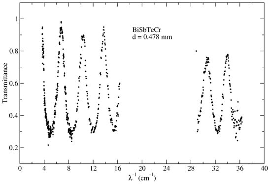
Figure 6.
Transmittance spectrum of the sample used in this work in zero magnetic field and at temperature K. This spectrum was measured in the parallel polarizers geometry, , and shows a series of Fabry-Pérot resonances due to reflections on the substrate surfaces.
Finally, we estimate the value of the magnetooptical Faraday effect on the polarization rotation in terahertz experiments. In calculations below, we neglect the influence of the substrate as the measurements are done in the maxima of the Fabry-Pérot interferences. In addition, we assume isotropic electromagnetic susceptibilities and the normal incidence. Then, in a thin sample approximation, i.e. for , the boundary conditions can be written in an extended manner that includes the sample as part of the surface [26,27]. The transmittance of eigenmodes for a magnetic thin film can then be written as
Here d is the sample thickness, is the permittivity, is the permeability for two circular polarizations, and is the radiation wavelength. We recall that in the present geometry circularly polarized waves are the eigenmodes of the system and that Equation (5) is closely similar to Equation (1) and to the purely magnetic case in Ref. [28].
We apply now the definitions given in Equation (2) to obtain the magnetic part of the polarization rotation via and :
Here are magnetic susceptibilities. Similar expression for the polarization rotation including magnetoelectric susceptibilities has been obtained in Ref. [27]. For a ferromagnetic material can be written as [28,29]:
where is the ferromagnetic resonance frequency in the Faraday geometry, is the static magnetization, is the gyromagnetic ratio, g is the Gilbert damping parameter and H is the external magnetic field (here we avoid using usual notation for the Gilbert damping).
The ferromagnetic resonance frequency can be estimated as GHz for fields below T. Therefore, the useful approximation in the present case is leading to a simple expression for the magnetic Faraday angle:
Finally, it should be noted that Equation (6) differs substantially from the expression used in the classical books by a factor of for BiTe [30]. The latter case is derived for a thick sample and it neglects the influence of the surfaces that are dominating in the thin-film geometry.
Author Contributions
Terahertz experiments, A.S.; Sample preparation, L.P., P.Z. and K.L.W.; writing of the manuscript A.P.; Project administration, A.P. and A.S. All authors have read and agreed to the published version of the manuscript.
Funding
This work was supported by Austrian Science Funds (Grants No. W-1243, No. P27098-N27, and No. I3456-N27). Open Access was funded by Austrian Science Funds (FWF).
Institutional Review Board Statement
Not applicable.
Informed Consent Statement
Not applicable.
Data Availability Statement
The data presented in this study are available on request from the corresponding author.
Conflicts of Interest
The authors declare no conflict of interest.
References
- Qi, X.L.; Hughes, T.L.; Zhang, S.C. Topological field theory of time-reversal invariant insulators. Phys. Rev. B 2008, 78, 195424. [Google Scholar] [CrossRef]
- Hasan, M.Z.; Kane, C.L. Colloquium: Topological insulators. Rev. Mod. Phys. 2010, 82, 3045–3067. [Google Scholar] [CrossRef]
- Yu, R.; Zhang, W.; Zhang, H.J.; Zhang, S.C.; Dai, X.; Fang, Z. Quantized Anomalous Hall Effect in Magnetic Topological Insulators. Science 2010, 329, 61–64. [Google Scholar] [CrossRef]
- He, K.; Wang, Y.; Xue, Q.K. Topological Materials: Quantum Anomalous Hall System. Annu. Rev. Condens. 2018, 9, 329–344. [Google Scholar] [CrossRef]
- Tokura, Y.; Yasuda, K.; Tsukazaki, A. Magnetic topological insulators. Nat. Rev. Phys. 2019, 1. [Google Scholar] [CrossRef]
- Zhang, J.; Chang, C.Z.; Tang, P.; Zhang, Z.; Feng, X.; Li, K.; Wang, L.l.; Chen, X.; Liu, C.; Duan, W.; et al. Topology-Driven Magnetic Quantum Phase Transition in Topological Insulators. Science 2013, 339, 1582–1586. [Google Scholar] [CrossRef]
- Liu, C.X.; Zhang, S.C.; Qi, X.L. The Quantum Anomalous Hall Effect: Theory and Experiment. Annu. Rev. Condens. 2016, 7, 301–321. [Google Scholar] [CrossRef]
- Chang, C.Z.; Zhang, J.; Feng, X.; Shen, J.; Zhang, Z.; Guo, M.; Li, K.; Ou, Y.; Wei, P.; Wang, L.L.; et al. Experimental Observation of the Quantum Anomalous Hall Effect in a Magnetic Topological Insulator. Science 2013, 340, 167–170. [Google Scholar] [CrossRef]
- Kou, X.; Guo, S.T.; Fan, Y.; Pan, L.; Lang, M.; Jiang, Y.; Shao, Q.; Nie, T.; Murata, K.; Tang, J.; et al. Scale-Invariant Quantum Anomalous Hall Effect in Magnetic Topological Insulators beyond the Two-Dimensional Limit. Phys. Rev. Lett. 2014, 113, 137201. [Google Scholar] [CrossRef]
- Kou, X.; Pan, L.; Wang, J.; Fan, Y.; Choi, E.; Lee, W.L.; Nie, T.; Murata, K.; Shao, Q.; Zhang, S.C.; et al. Metal-to-insulator switching in quantum anomalous Hall states. Nat. Commun. 2015, 6, 8474. [Google Scholar] [CrossRef]
- Mogi, M.; Yoshimi, R.; Tsukazaki, A.; Yasuda, K.; Kozuka, Y.; Takahashi, K.S.; Kawasaki, M.; Tokura, Y. Magnetic modulation doping in topological insulators toward higher-temperature quantum anomalous Hall effect. Appl. Phys. Lett. 2015, 107, 182401. [Google Scholar] [CrossRef]
- Okada, K.N.; Takahashi, Y.; Mogi, M.; Yoshimi, R.; Tsukazaki, A.; Takahashi, K.S.; Ogawa, N.; Kawasaki, M.; Tokura, Y. Observation of topological Faraday and Kerr rotations in quantum anomalous Hall state by terahertz magneto-optics. Nat. Commun. 2016, 7, 12245. [Google Scholar] [CrossRef] [PubMed]
- Ou, Y.; Liu, C.; Jiang, G.; Feng, Y.; Zhao, D.; Wu, W.; Wang, X.X.; Li, W.; Song, C.; Wang, L.L.; et al. Enhancing the Quantum Anomalous Hall Effect by Magnetic Codoping in a Topological Insulator. Adv. Mater. 2018, 30, 1703062. [Google Scholar] [CrossRef] [PubMed]
- Avron, J.E.; Osadchy, D.; Seiler, R. A Topological Look at the Quantum Hall Effect. Phys. Today 2003, 56, 38–42. [Google Scholar] [CrossRef]
- Qi, X.L.; Zhang, S.C. Topological insulators and superconductors. Rev. Mod. Phys. 2011, 83, 1057–1110. [Google Scholar] [CrossRef]
- Wu, L.; Salehi, M.; Koirala, N.; Moon, J.; Oh, S.; Armitage, N.P. Quantized Faraday and Kerr rotation and axion electrodynamics of the surface states of three-dimensional topological insulators. Science 2016, 354, 1124. [Google Scholar] [CrossRef]
- Lubatsch, A.; Frank, R. Behavior of Floquet Topological Quantum States in Optically Driven Semiconductors. Symmetry 2019, 11. [Google Scholar] [CrossRef]
- Shuvaev, A.M.; Astakhov, G.V.; Brüne, C.; Buhmann, H.; Molenkamp, L.W.; Pimenov, A. Terahertz magneto-optical spectroscopy in HgTe thin films. Semicond. Sci. Technol. 2012, 27, 124004. [Google Scholar] [CrossRef]
- Shuvaev, A.; Dziom, V.; Kvon, Z.D.; Mikhailov, N.N.; Pimenov, A. Universal Faraday Rotation in HgTe Wells with Critical Thickness. Phys. Rev. Lett. 2016, 117, 117401. [Google Scholar] [CrossRef]
- Dziom, V.; Shuvaev, A.; Mikhailov, N.N.; Pimenov, A. Terahertz properties of Dirac fermions in HgTe films with optical doping. 2D Mater. 2017, 4, 024005. [Google Scholar] [CrossRef]
- Dziom, V.; Shuvaev, A.; Pimenov, A.; Astakhov, G.V.; Ames, C.; Bendias, K.; Böttcher, J.; Tkachov, G.; Hankiewicz, E.M.; Brüne, C.; et al. Observation of the universal magnetoelectric effect in a 3D topological insulator. Nat. Commun. 2017, 8, 15197. [Google Scholar] [CrossRef] [PubMed]
- Onoda, M.; Nagaosa, N. Quantized Anomalous Hall Effect in Two-Dimensional Ferromagnets: Quantum Hall Effect in Metals. Phys. Rev. Lett. 2003, 90, 206601. [Google Scholar] [CrossRef] [PubMed]
- Zvezdin, A.K.; Kotov, V.A. Modern Magnetooptics and Magnetooptical Materials; Condensed Matter Physics; Taylor & Francis: New York, NY, USA, 2010. [Google Scholar]
- Bestwick, A.J.; Fox, E.J.; Kou, X.; Pan, L.; Wang, K.L.; Goldhaber-Gordon, D. Precise Quantization of the Anomalous Hall Effect near Zero Magnetic Field. Phys. Rev. Lett. 2015, 114, 187201. [Google Scholar] [CrossRef] [PubMed]
- Volkov, A.A.; Goncharov, Y.G.; Kozlov, G.V.; Lebedev, S.P.; Prokhorov, A.M. Dielectric measurements in the submillimeter wavelength region. Infrared Phys. 1985, 25, 369. [Google Scholar] [CrossRef]
- Oksanen, M.I.; Tretiakov, S.A.; Lindell, I.V. Vector circuit-theory for isotropic and chiral slabs. J. Electromagn. Waves Appl. 1990, 4, 613. [Google Scholar] [CrossRef]
- Szaller, D.; Shuvaev, A.; Mukhin, A.A.; Kuzmenko, A.M.; Pimenov, A. Controlling of light with electromagnons. Phys. Sci. Rev. 2020, 5, 20190055. [Google Scholar] [CrossRef]
- Weymann, L.; Shuvaev, A.; Pimenov, A.; Mukhin, A.A.; Szaller, D. Magnetic equivalent of electric superradiance: Radiative damping in yttrium-iron-garnet films. arXiv 2020, arXiv:2012.09440. [Google Scholar]
- Gurevich, A.; Melkov, G. Magnetization Oscillations and Waves; CRC Press: Boca Raton, FL, USA, 1996. [Google Scholar]
- Greenaway, D.L.; Harbeke, G. Band structure of bismuth telluride, bismuth selenide and their respective alloys. J. Phys. Chem. Sol. 1965, 26, 1585. [Google Scholar] [CrossRef]
Publisher’s Note: MDPI stays neutral with regard to jurisdictional claims in published maps and institutional affiliations. |
© 2021 by the authors. Licensee MDPI, Basel, Switzerland. This article is an open access article distributed under the terms and conditions of the Creative Commons Attribution (CC BY) license (http://creativecommons.org/licenses/by/4.0/).