Article

Computational Modeling of Dislocation Slip Mechanisms in Crystal Plasticity: A Short Review

by
Khanh Nguyen
1,*,
Meijuan Zhang
2,
Víctor Jesús Amores
1,
Miguel A. Sanz
1 and
Francisco J. Montáns
1,3,*
1
E.T.S. de Ingeniería Aeronáutica y del Espacio, Universidad Politécnica de Madrid, Plaza Cardenal Cisneros 3, 28040 Madrid, Spain
2
Imdea Materials Institute, Tecnogetafe, Eric Kandel Street 2, 28906 Getafe, Spain
3
Department of Mechanical and Aerospace Engineering, Herbert Wertheim College of Engineering, University of Florida, Gainesville, FL 32611, USA
*
Authors to whom correspondence should be addressed.
Crystals 2021, 11(1), 42; https://doi.org/10.3390/cryst11010042
Submission received: 9 December 2020 / Revised: 25 December 2020 / Accepted: 30 December 2020 / Published: 4 January 2021
(This article belongs to the Special Issue Crystal Plasticity)

Abstract

:
The bridge between classical continuum plasticity and crystal plasticity is becoming narrower with continuously improved computational power and with engineers’ desire to obtain more information and better accuracy from their simulations, incorporating at the same time more effects about the microstructure of the material. This paper presents a short overview of the main current techniques employed in crystal plasticity formulations for finite element analysis, as to serve as a point of departure for researchers willing to incorporate microstructure effects in elastoplastic simulations. We include both classical and novel crystal plasticity formulations, as well as the different approaches to model dislocations in crystals.

1. Introduction

Analysis of the plastic deformations of metals is very important in many aspects of the design of metallic goods, for example, in the design of the alloys which will be used in the components, in their manufacturing process (e.g., shape forming), and in the behaviour of the material in service, both to sustain the ordinary actions and to behave in a controlled, predictable way (fracture, fatigue, crash-worthiness, etc.) [1,2].
Plastic slip is the most common plastic deformation mechanism in crystalline solids, e.g., most of the metals. This slip takes place as a plastic shearing in specific planes and directions governed by the arrangement of the atoms in a regular crystal structure [3]. This arrangement produces anisotropic elastic and plastic properties depending on the packing of atoms into planes. Compact planes slide in particular directions, a movement which is facilitated by the presence of dislocations (defects in the crystal arrangement, e.g., by the absence of atoms in the structure, line defects). Plastic slips in crystals is a plastic process that does not change the volume. However, for materials whose dominant deformation mechanism is slip, it is usually the origin of yield stress and hardening in macroscopic plasticity. Then, the study of crystal plasticity is fundamental to understand in a rational way the macroscopic behavior of the polycrystal, and how different aspects of the microstructure affect this behavior and the observed critical quantities like yield stress, elastoplastic anisotropy, anisotropic local and global deformation, hardening, thermal properties, etc. [4]. In the late 20th and beginning of the the 21st Century, after the work of Pierce et al. [5], thanks to improved computational power, crystal plasticity finite element simulations have received an important boost because these multiscale procedures, in which the studied phenomena has a length scale of µ m, can now be addressed computationally. Then, computational homogenization schemes [6] are a typical procedure to bring the microscale complexity to the macroscale in a simple, standarized way. Thus, current computational power increasingly facilitates this type of analysis, bringing classical materials science to the engineering office [7].
Whereas the scale at which dislocation movements takes place is much smaller than the continuum scale (or precisely because of that, which facilitates the requirement of separation of scales), many effects may be studied at a mesoscale if we consider that a given stress integration point represents a homogenization of the grain, or part of the grain, so crystal plasticity computations give an implicit Representative Volume Element (RVE) of the dislocation theory, being the direction of the Burgers vector the sliding direction, and its modulus the computed sliding times the length of the RVE [8,9].
The choice of crystal plasticity theory as the simulation tool for different inelastic phenomena depends itself on the objectives of such simulation. Several aspects of the behavior of materials are easily extracted from this type of simulations. Examples are texture evolution (e.g., anisotropy symmetries evolution as a result of the evolution of crystallographic planes and grain structure), effects of grain size, effects of twinning or impurities, speed of deformation, influence of grain shape (e.g., after cold forming), etc. Furthermore, damage in these materials due to void nucleation in grain boundaries has also been studied through crystal plasticity simulations (e.g., [10,11], see also [12]). The coupling between the crystal plasticity and phase-field damage is also proposed to study the fracture [13,14]. There are other options, mainly computational, to model plasticity-based phenomena at different scales, specially through the combination of one scale with a larger one in which the desired effect needs to be accounted for. Examples are atomistic models [15,16], dislocation dynamics models [17], and continuum models [18,19]. However, crystal plasticity is probably the most used framework for incorporating the grain and crystal structure as well as the inherent effects of dislocations in the continuum modelling. Then, in this paper after a brief review of the physical aspects, we perform a review of the main ingredients and formulations employed today in crystal plasticity simulations. We finish with some demonstrative simulations as examples of the possibilities of crystal plasticity. The purpose of the review is to serve as an introductory compact presentation of current mostly used formulations for researchers (e.g., continuum mechanics ones) becoming involved in the subject or willing to incorporate texture effects in advanced simulations, for example, by computational homogenization. It is by no means a complete review, so many important works and formulation aspects, are omitted. Advanced long reviews taylored for researchers in materials science are available elsewhere [20,21,22].

2. Mechanism of Dislocation Slip: Physical Aspects

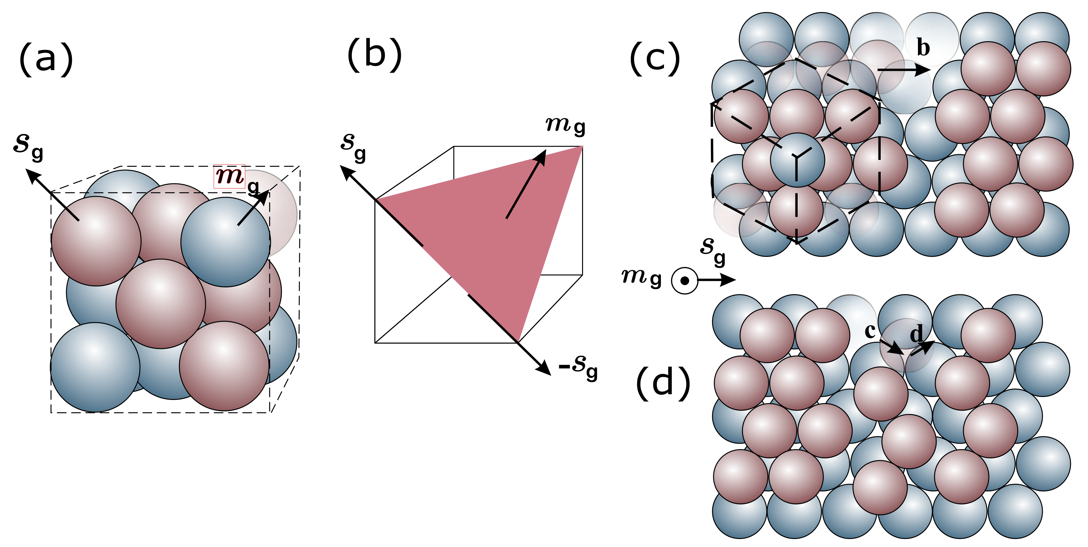
Crystals have different structural arrangements of atoms, see e.g., Figure 1. Directions and planes are labeled according to Miller indices with reference to the unit cell edge vectors e i . For example, direction s g = 1 / 2 ( 1 e 1 + 1 e 2 + 0 e 3 ) in a face-centered cubic (FCC) is referred to direction [ 1 ¯ 10 ] (in brackets, using integers and with possible minus signs over the number), and the plane perpendicular to m g = ( 1 e 1 + 1 e 2 + 1 e 3 ) / 3 is referred to as plane ( 111 ) in the present FCC case; see Figure 2. Equivalent families of directions and planes (physically equivalent, obtained by rotations/symmetries) are referred to as 110 = [ 1 ¯ 10 ] , [ 1 1 ¯ 0 ] , [ 110 ] and { 111 } = [ 111 ] , [ 1 ¯ 11 ] , [ 1 1 ¯ 1 ] , [ 11 1 ¯ ] , respectively for a FCC. In the case of hexagonal crystals, four indices are often employed to allow permutations when referring to families, one index along each possible edge direction, being the last one the height c direction, Figure 1. The prismatic planes of HCP are ( 0001 ) and { 1 1 ¯ 00 } = ( 10 1 ¯ 0 ) , ( 01 1 ¯ 0 ) , ( 1 ¯ 100 ) , i.e.,  ( h k l ) ( h k i l ) with i = h k (not normal), whereas the directions conversion is ( u v w ) ( U V T W ) with U = ( 2 u v ) / 3 , V = ( 2 v u ) / 3 , T = ( u + v ) , W = w , e.g., the edges are the permutations of [ 2 1 ¯ 1 ¯ 0 ] and [ 0001 ] . The FCC arrangement (Figure 2a) has atoms at the vertices and center of the faces of an ideal hexahedron, resulting in a dense arrangement, and is typical of specially ductile materials (e.g., Al, Cu, Au, Ag). FCC crystals have four { 111 } planes with three 110 directions in each plane, therefore in total have 12 slip systems, referred to as { 111 } 110 . Body centered cubic crystals (BCC), (Cr, Fe, W) have atoms in the vertices and in the center of the hexahedron, and usual slip planes in the { 110 } family and direction 1 ¯ 11 (secondary slip systems may become active for some materials and temperatures). Hexagonal close-packed arrangements have planes { 0001 } , { 10 1 ¯ 0 } , { 10 1 ¯ 1 } with directions 11 2 ¯ 0 , although the basal plane slip { 0001 } is favored for high height/base ratios (e.g., Mg, Co, Zn), and the other ones for lower ratios (e.g., Be, Ti, Zr); these materials have a more limited slip.
Dislocations are crystal defects which result, for example, from the absence of some atoms in the otherwise regular arrangement, see Figure 2c,d. Microscopically, slip is a result of the glide of many dislocations, facilitated by the stress field generated around them. This glide does not happen simultaneously in all the grain, but occurs in a worm-like movement, see Figure 3. The glide motion of a dislocation means that the dislocation moves in the plane which contains both its line and the Burgers vector b (Figure 2c). Dislocations and their associated local stress fields interact, blocking or further facilitating their movement. The accumulation of hundreds or even thousands of these displacements form a slip band. These slip bands can be easily observed on the surfaces of polished specimens which have been subjected to plastic deformation. Dislocations, slip bands and slip displacements are small with respect to the size of the grains, so even when the grain microstructure is considered, this plastic slip can be treated as homogeneous from a macroscopic standpoint [25]. The dislocation mechanisms can be homogenized in the form of statistical dislocation populations, and therefore, can be embedded in state evolution constitutive equations in a crystal plasticity theory.
For a certain crystal, a slip system is determined by the normal direction of the slip plane m g (which we can call the plane “direction”) and the slip direction s g in the crystal coordinate system. In Figure 2a,b, the plane formed by red atoms is a typical slip plane in a FCC crystal. At the atomic level, the forming of slip requires some breaking and reforming of dislocation-stressed interatomic bonds. This can be interpreted as a plane of atoms sliding over another parallel one on the slip plane, with the sliding direction as the slip direction. This is a volume-preserving shearing process that is typically not affected by the hydrostatic stress [26]. Slip planes m g are planes with the highest packing or atom density, whereas the slip directions s g are usually directions in these slip planes in which the atoms have the closest packing, see again Figure 2. The dyad s g m g constitutes the slip system and γ ˙ g is the slip (shearing) rate. Sliding may occur in the positive + s g and negative s g directions (hence a FCC crystal may have 4 × 3 = 12 slip systems).
Other important quantities of a slip system are the resolved shear stress (RSS) and the critical resolved shear stress (CRSS). The former is the shear stress in the plane and direction of the slip system, and the latter is the critical value for which sliding occurs. For most crystals, the CRSS values of a certain slip system for both “+” and “−” directions can be assumed to be the same [25].
The CRSS of a slip system depends on many factors, among them previous slips and the crystal structure itself, because they play an important role due to the difficulty in breaking and reforming interatomic bonds. Also, an increase in the temperature (increasing vibration) or decrease in the strain rate (facilitating adaptation) increase the thermal activation of atoms and allow dislocations to overcome obstacles more easily. This results in an effective lower CRSS [27,28,29]. Of course, the modification of the material composition by adding other elements increase in general obstacles (breaking crystal regularity) and could interrupt the glide of the dislocations as the case of BCC iron micropillar [30]. Dislocations pile-up occurs as a cluster of dislocations which are unable to move past the grain boundary. Each successive dislocation will apply a repulsive force to the dislocation incident with the grain boundary. These repulsive forces act as a driving force to help overcoming the energetic barrier for diffusion across the boundary, such that additional pile up causes dislocation diffusion across the grain boundary, allowing further plastic deformation in the material. Decreasing grain size decreases the statistical amount of possible pile up at the boundary, increasing the amount of applied stress necessary to move a dislocation across a grain boundary. The higher the applied stress needed to move the dislocation, the higher the macroscopic yield stress [27]. This effect is well known as the Hall-Petch effect/law [31,32]. Of course, given a grain size, these effects deppend on the amount of statistical dislocations and other deffects.
In essence, slip plane m g , slip direction s g and the CRSS τ g c are crucial features of a slip system. According to the Schmid law, they determine which slip systems are “active” (sliding) [33]. The crystal structure is anisotropic, and the elasticity and plastic slip are also anisotropic. Furthermore, different slip systems can have different CRSS, which further determine the anisotropy of the material. This holds especially if the material is a single crystal or a polycrystal with a strong texture. Only when the material is a polycrystal that has a large number of different crystallographic orientations, the material can be considered as statistically isotropic on average; and von Mises plasticity is adequate. If the crystallographic orientation has a defined statistical distribution, continuum anisotropic models using Hill’s or Barlat’s yield functions with anisotropic or isotropic elasticity may also be adequate in some cases. However, note that in continuum plasticity tracking the macroscopic evolution of such anisotropy is not simple [34], which is a good reason to resort to crystal plasticity.
Rate-dependent crystal plasticity modeling is all about computing the shear amount of the activated slip systems from which the overall plastic deformation follows. The key point becomes how to describe/model the evolution of the CRSS of slips. The “hardening” evolution of the CRSS of slips is caused microscopically by the overcoming obstacles during slip gliding and from the interaction with other dislocations, as well as from the generation and annihilation of dislocations. As mentioned, temperature and strain rate are related to the thermal activation, so they are also related to the easiness for a dislocation to glide [27]. Different types of obstacles (as grain boundaries, solutes, and precipitates or other phases) may hinder gliding [30]. Of course, some factors changing the dislocation density or which may influence the interactions among dislocations may contribute to work hardening. An important one is the already pre-existing dislocation density. As well known, this could be reduced by heat treatments like annealing. Active secondary slip systems can cause multiplication of dislocations. Slip transfer at grain boundaries and cross slip can cause annihilation of dislocations. Stress concentrations (mainly at grain boundaries) can even cause the nucleation of dislocations. In practice, the different cross-interactions between dislocations which increase the CRSS are accounted for by means of the latent hardening [35,36,37].
As explained below, to prescribe the evolution of the CRSS of the slip system, different models have been proposed in the literature by relating its value and evolution to different variables during deformation. One widely used category follows a “phenomenological” approach [5,38,39,40]. They relate the evolution of the CRSS with the shear rate of all the activated slip systems. Another popular type are the “physical” models, which are dislocation-density based. This type of model relates the evolution of the CRSS with the evolution of the dislocation density of all the slip systems, e.g., the Taylor law [41], the early models [42,43]. This approach is extended to account for more detailed factors that influence hardening, e.g., the annihilation of dislocations [44]; the latent hardening [45,46,47]; the grain size effect [48]; the slip transfer at the grain boundary [49]; the influence of strain gradient [50]; the incorporation of phase transformation [51].
Dislocation slip mechanisms are not the only ones present in crystals producing permanent deformations. Aside, there are other types of mechanisms as displacive (difusionless) transformations and twinning. The former is a rearrangement of the atoms of a crystal structure to form another structure without a relevant change in volume. The most important case appears in carbon steels (e.g., martensitic transformations). Another plastic mechanism is twinning deformation, which produces mirrored structures. The treatment of these additional mechanisms are out of the scope of this review.

3. Continuum Framework of Crystal Plasticity

3.1. Kinematics

As mentioned, the structure of a crystalline solid at the µ m scale may be understood, and hence it is often modelled, as an aggregate of volume elements (finite elements), or lattice blocks (voxels). This constitutes the reference “undeformed” lattice, which contains dislocations (hence microscopically deformed); Figure 2. At the continuum scale (e.g., at a stress integration point in a finite element, computed from the reference coordinates X , the updated coordinates x = X + u , and displacement field u as F = x / X = I + X u with X being the reference-coordinates gradient), the deformation can be considered as composition of two basic mechanisms that take place simultaneously: (1) slip between lattice blocks (as an homogenization of dislocation slips), followed by (2) elastic lattice distortions which include (3) lattice rotations (local or “elastic” and rigid-body) that also arise under a general deformation gradient F . Rotations produce observable phenomena of geometric origin, such as the geometric softening of crystals due to their reorientation [52] (similar to structural P- δ effects). In consequence, at large deformations, Kröner and Lee [53] introduced a multiplicative decomposition of F into plastic slips and crystal “elastic” deformations [54,55]. Whereas F is a compatible deformation gradient ( X -integrable from the potential u ( X ) or F 1 is x integrable from u ( x ) ), it is decomposed into two (local, incompatible) deformation components as:
F = F e F p
where the plastic deformation gradient F p is irreversible and transforms the reference configuration into a fictitious local state, termed intermediate configuration. This (“elastically unloaded”) intermediate configuration is “stresses-free” and is considered to maintain an “undeformed” slipped lattice. In turn, the elastic deformation gradient F e is the deformation considered reversible, and includes rigid body rotations; namely after an overimposed rotation Q we have F + : = Q F = Q F e F p = F e + F p . The possible indeterminacy of the intermediate configuration respect to arbitrary rotations of the type F e Q T Q F p has involved several discussions (see e.g., [56,57,58]). In summary, specially in the case of crystal plasticity, F p is continuously time-integrated, so it is always uniquely defined. Remarkably, the conservative/dissipative character of the two gradients give an important physical difference in their polar decompositions: whereas F e = R e U e is meaningful in the sense that R e are path-independent rotations which in principle do not enter the constitutive equations and U e are path-independent stretches that may be used in a stored energy as state variables, F p = R p U p is physically meaningless because the crystallographic slip does not change the orientation of the crystal lattice even though F p include mathematically a rotational part; stretch and rotations are related by the isoclinic flow and must be considered in an incremental setting. Indeed, this is an argument to build the formulation in terms of elastic measurements, avoiding also weak-invariance issues [59,60].
As mentioned, whereas F is compatible, the gradients F e and F p are incompatible, meaning that for general non-homogeneous deformations we have
b ¯ = Γ d ξ = Γ F p · d X = Γ d X · F p T 0
where d ξ is the transformation in the intermediate configuration of the material differential d X , and Γ is the transformation of a close circuit C in the reference configuration, i.e., C d X = 0 . Even though the gradients are to be interpreted in a continuum sense (at a scale much larger than that of the dislocations), b ¯ represents the resultant Burgers vector (net Burgers vector of the dislocations tansversing Γ ); it may be conceptually interpreted as the Burgers vector b (the sign may be reversed) when one dislocation is present; i.e., b ¯ has a modulus proportional to the amount (density) of dislocations; see an ilustration of the concept in Figure 4 motivated in the typical Burgers circuit, and a discussion of the continuum/crystallographic views in [61]. To the last integral in Equation (2), the generalized Stokes theorem may be applied
Γ d L A = S Γ ( d s × ) A
where S Γ is a surface with support on Γ , d L is a line differential of Γ , and d s is a surface differential of S Γ . The operation * is any operation consistent with the physical object A (vector or tensor of any order), and indicates that the operator operates on A . Then
b ¯ = Γ d X · F p T = S Γ ( d s × X ) · F p T = S Γ ( X × F p T ) T · d s
where the last identity is inmmediate using index notation. In dislocation density based models, the Kröner-Nye tensor α is handy [62,63], usually defined as the tensor field α ( X ) such that
b ¯ = b b ^ = S Γ α · d s α = 1 b ( X × F p T ) T
Of course, because the deformation gradient F is compatible, so c F e F p · d X = c d X = 0 , the same integral may be obtained from the spatial configuration and d ξ = F p · d X = F e 1 · d X ; i.e., α ( X ) = 1 / b ( x × F e T ) T . For the case of infinitessimal deformations, splitting the local displacement into elastic and plastic local (incompatible) parts ( u = e e + u p ) , we immediately obtain α = 1 b ( × ( u p ) T ) T = 1 b ( × ( u e ) T ) T , where we used the small strains approximation F e 1 I u e . Note that for homogeneous elastic or plastic deformations α = 0 (dislocations are not geometrically needed because gradients are compatible). Indeed, Nye related them with the curvature in the deformation field.
The multiplicative decomposition is accepted in crystal plasticity, but at a single integration point in a finite element program, the  decomposition assumes that the represented volume is fully transversed by dislocations. However, in reality, this assumption is not fulfilled; in general, there is still a dislocation content between neighboring material points if both experience different slip system activity from nonhomogeneous deformations, even if a full traverse by dislocations or a (statistical) homogeneous population is considered for individual material points. Much research is ongoing in the seek of the best formulation to take into account these effects [64,65,66,67,68,69,70,71,72,73].
The constitutive law can be obtained from the Helmholtz free energy density expressed in the intermediate configuration as proposed by [8,69,74]. The free energy density can be decomposed into the elastic and plastic parts [8]. The elastic part is recoverable through elastic strain unloading, whereas the plastic part needs some plastic deformation to recover it (accounts for example, for kinematic hardening).
Ψ = Ψ e ( F e ) + Ψ p ( F p , q )
where q is a set of internal variables. The second Piola-Kirchhoff stress tensor in the intermediate configuration then is obtained, for example, using Green-Lagrange strains, as 
s | e = d Ψ e d E e
being E e the Green-Lagrange elastic strain tensor and s | e its work-conjugate stress tensor (both living in the intermediate configuration). Note that the strain energy may be written in terms of any arbitrary deformation measure, and the derivative of the energy respect to that measure gives the work-conjugate stress measure in the same configuration. If the elastic strain energy Ψ e is defined by a quadratic potential of the Green-Lagrange elastic strains, s | e can be obtained as a linear function of E e ,
s | e = C : E e = 1 2 C : ( F e T F e I )
where C is the fourth-order elastic tangent moduli tensor of the single crystal.
Considering the decomposition in Equation (1), the velocity gradient L can similarly be decomposed:
L = F ˙ F 1 = F ˙ e F e 1 L e + F e F ˙ p F p 1 L p F e 1 = L e + F e L p F e 1
being L e and L p the elastic and plastic velocity gradients. It is noted that the total deformation gradient is decomposed multiplicatively, whereas the decomposition of total velocity gradient is additive. Furthermore, both L and L e are defined with respect to the current configuration. The plastic velocity gradient L p , however, lives in the intermediate configuration, so it requires a mapping (push forward) from the intermediate to the current configuration, as shown by Equation (9).
Rice [54] assumed that for multislips, the plastic velocity gradient L p is the sum of all crystallographic slip rates:
L p = g γ ˙ g s g m g
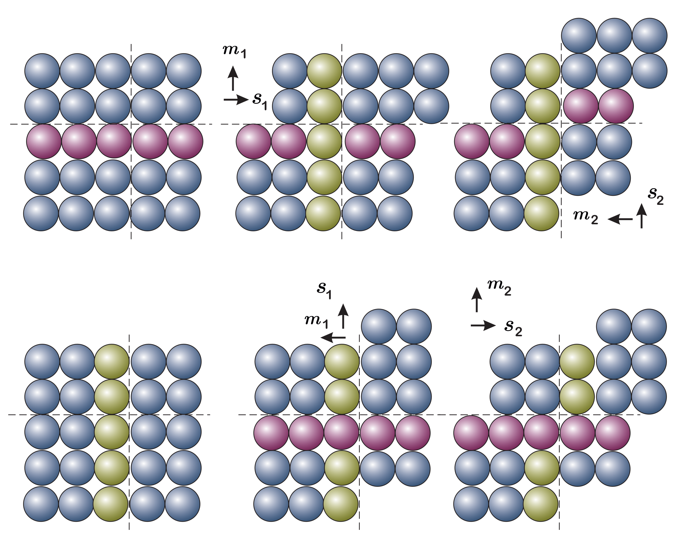
where γ g is the internal variable that accounts for the accumulated plastic slip in each glide (slip) system g; vectors m g and s g are, respectively, unit normal vector to the slip plane and the unit vector in the slip direction that define the same glide system g in the reference configuration. An important aspect here is that the addition in Equation (10) is not exact in discrete algorithms, because the order in which the different slips take place changes the final result. The reason is that after one slip has taken place, L p for the next one would be in a different configuration; see Figure 5. However, the approximation is considered acceptable in the literature given that steps are typically small. Indeed, recently we have proposed a different framework in terms of corrector rates [75], which results immediately from the chain rule applied to F e ( F , F p ) FF p 1 , namely
F ˙ e = F e F F ˙ p 0 F ˙ + F e F F ˙ 0 F ˙ p = : t r F ˙ e + c t F ˙ e
where c t F ˙ e is the continuum corrector rate of the elastic gradient, and  t r F ˙ e is the continuum trial rate of the elastic gradient; see further details about the elastic corrector rates framework in [75,76,77,78]. In this case, Equation (9) may be written as
L e = L F e L p F e 1 = t r L e + c t L e
where t r L e is the elastic rate with the plastic flow frozen (the concept of a partial derivative), and c t L e is the elastic rate with the external power frozen. Then, as an alternative to Equation (10), the following addition takes place in the same trial-frozen configuration:
c t L ˜ e = c t F ˙ e c t F e 1 = g γ ˙ g s g m g
As a key difference, this poses an evolution on the elastic deformation gradient instead of on the plastic one, facilitating by construction the weak-invariance property.

3.2. Constitutive Models

3.2.1. Phenomenological Models

In crystal plasticity, the phenomenological models can be considered as the first approach adapted from the framework of continuum mechanics, and are dominant in the literature. This approach uses mostly the resolved shear stress (RSS) τ g on a glide system g, as material state variable. With s | e denoting the second Piola-Kirchhoff stress tensor in the intermediate configuration, the RSS on glide system g, is typically defined as:
τ g = F e T F e s | e : ( s g m g )
where F e T F e s | e is the non-symmetric Mandel stress tensor. In the case of infinitesimal elastic strains which typically hold in crystal plasticity, Equation (14) can be approximated as:
τ g s | e : ( s g m g )
An alternative is to use the recent formulation based of elastic corrector rates, which do not involve the Mandel stress tensor, but the symmetric generalized Kirchhoff one [75,79,80,81]. This formulation has general validity (not only for infinitesimal elastic strains). In general, the stress is defined as the derivative of the stored energy respect any convenient strain measure, for example, the logarithmic (Hencky) elastic strains H e : = 1 2 log ( F e T F e ) in the intermediate configuration, namely
T | e : = d Ψ ( H e ) d H e   such   that   D = Ψ ˙ F ˙ = 0 = T | e : c t H ˙ e
where D is the plastic dissipation and c t H ˙ e is the corrector rate of H ˙ e (the one with the external power frozen). Plastic slip occurs in this glide system when τ g reaches a critical level τ g c (CRSS) that is typically considered as a function of the total accumulated plastic slip γ = γ ˙ d t and its rate γ ˙ = γ ˙ g ,
τ g c = f ( γ , γ ˙ )
This CRSS value can be interpreted as the hardened yield stress of the slip system. In inviscid plasticity γ ˙ > 0 just when τ g > τ g c . In rate dependent plasticity, the slip rate in each glide system is then formulated as a function of the RSS τ g and the CRSS τ g c (e.g., as their ratio),
γ ˙ g = f ( τ g , τ g c )
Much work was performed to establish the specific form of Equation (18), e.g., [5,54,55,82,83], who have formulated a power-law function for slip rate as a common choice (other options are possible):
γ ˙ g = γ ˙ 0 | τ g | τ g c 1 / m sign ( τ g )
being γ ˙ 0 and m material parameters that quantify the reference shear rate and the rate sensitivity of the slip mechanism, respectively. τ g c is also referred to as strength or hardness of the slip system. In the above equation γ ˙ g can take both signs, while in the original work of Pierce et al. [82] the positive and negative slip directions are considered. The sensitivity exponent and the reference shear rate may include the influence of the temperature, for example, as [84,85]
m = k T τ f µ b 2 d and γ ˙ 0 = ρ m b 2 f D exp Δ G k T
where k is the Boltzmann constant, T the absolute temperature, µ the shear modulus, τ f is the average strength of the forest, d is the distance to overcome an obstacle, ρ m is the density of the mobile dislocations (see below), Δ G is the stored Gibbs free energy when a dislocation bypasses an obstacle, and f D is the Debye characteristic frequency of the crystal, given by
f D = 3 N 4 π V 1 3 v s
where N / V is the number of atoms per volume and v s is the speed of sound. Typical values are [85] d 4 b , Δ G µ b 3 / 5 , m 0.005 , γ ˙ 0 10 16 ÷ 10 6 [ s 1 ] .
For the hardening evolution of the CRSS τ g c in each glide system, a hardening law is typically defined. A formulation proposed by Peirce et al. [82] for isotropic type hardening is often used. It includes the explicit contributions of the occurring slip in the same glide system (self-hardening) and of the cross-effect from slips on all other glide systems (latent hardening):
τ g c ˙ = j h g j | γ ˙ j |
Here h g j is a matrix of hardening coefficients, fitted/determined empirically to capture the micro-mechanical interaction between the different slip systems [82]:
h g j = h ( γ ) [ q + ( 1 q ) δ g j ]
The material parameter q differentiates latent hardening and self hardening of the glide systems; typically in an interval [ 1 , 1.4 ] . For FCC single crystals, a typical choice for the hardening function h ( γ ) is [82]:
h ( γ ) = h 0 sec h 2 h 0 γ τ s τ 0
being h 0 the initial hardening rate. τ 0 and τ s denote initial and saturation values for the CRSS.
We note that Equations (19), (22) and (24) are not the only ones proposed in the literature. Some researchers [86,87,88,89,90,91] modify Equation (19) to take into account the cyclic deformation by introducing a phenomenological backstress term to formulate the kinematic hardening. Other authors [92,93] use classical hardening laws from continuum plasticity such as Voce’s hardening law to avoid vanishing hardening rates though the introduction of a limiting slope.

3.2.2. Physics-Based Models

In contrast to the phenomenological models, the physics-based ones use physical (or physically motivated) measures, as well as principles and important physical insight from microstructure information and its evolution. Examples of that information are dislocation density, precipitate morphology, grain size and shape, etc. Nevertheless, only a few of these aspects have been introduced into physics-based models. In following subsections, we present more in detail some predominant models.

(a) Dislocation density-based models

There are 10 6 to 10 12 dislocations in every cm 2 of material. The amount is variable and strongly depends on the processing history, in particular deformation and thermal treatments, possibly on microstructure [27,94]. Whereas dislocations are mostly responsible for plastic deformation, crystal plasticity models are usually developed at a different scale. Then, the different scales are considered throughout the formulations in terms of statistically stored dislocation (SSD) densities in the crystal plasticity models. At a given time, there are two types of SSD: mobile (glissile) and immobile (sessile), with respective densities ρ g m and ρ g i m ; in total ρ g = ρ g m + ρ g i m . These densities represent the equivalent length of dislocations (Burgers vectors) along a direction per unit volume, e.g., with units [m/m 3 ] = [m 2 ]. Mobile dislocations are the ones producing effective slips, but during deformation a change of status of dislocations is possible [95,96] which means a transfer between ρ g m and ρ g i m . This decomposition has been proposed to develop a different treatment needed for both components, because mobile dislocations are the source of plastic deformation and ductility; whereas immobile dislocations block motion, strengthening or hardening the material. The laws of evolution for mobile dislocations require a coupling with the ones for immobile dislocations. The evolution laws for dislocation density is typically based in the following Kocks-Mecking model [95,97,98]:
ρ ˙ g = 1 b g 1 l ( ρ g ) 2 γ c ρ g | γ ˙ g |
This law includes both storage and recovery effects (in a similar layout to the Armstrong-Frederick rule in hardening) that determine the variation of the dislocation density with plastic deformation. The first addend in the brackets accounts for the storage of dislocations 1 / ( b g l ( ρ g ) ) ; the dynamic recovery by the term 2 γ c ρ g is associated with the annihilation of stored dislocations. The function l ( ρ g ) is interpreted as immobilization of mobile dislocations at obstacles after having travelled a characteristic (statistical average) distance. b g is the Burgers vector modulus of slip system g. The term γ c is the critical annihilation distance. Some modifications of Equation (25) are possible; refer, for example, to [99,100].
Further evolution laws for metals of different crystal structures is proposed in [101] and enhanced by subsequent works [102,103,104,105]. An example is the following which is a linear superposition of various mobile and immobile mechanisms:
ρ ˙ g m = h g s ( ρ g i m ρ g m ) 1 h g m 0 ρ g m h g i m 0 ρ g i m | γ ˙ g |
ρ ˙ g i m = h g m 1 ρ g m h g i m 1 ρ g i m h g r ρ g i m exp Δ G k T 1 ρ g i m ρ s a t i m | γ ˙ g |
where ρ s a t i m is an experimentally determined saturation for immobile dislocation densities, The coefficients h g s , h g m 0 , h G i m 0 , h g m 1 , h g i m 1 and h g r depend on the degree of activity of the specific dislocation mechanisms g.
Regarding the evolution of the slip rate, in dislocation-based models the equation proposed by Orowan [106] is typically used instead of Equation (19) as it establishes the connection between the plastic slip rate on a given glide system γ ˙ g and the mobile dislocation density, i.e., it creates a bridge to convert a continuum mechanical term into the physics of dislocations:
γ ˙ g = ρ g m b g v g
where ρ g m is the mobile dislocation density, b g is the Burgers vector modulus of g and v g is the average velocity of mobile dislocations that depends on the details of the evolving dislocation mechanism. During slip, depending on whether thermal activation can contribute to get over the obstacle, the barriers to dislocation movement can be referred to as temperature-dependent or independent.
Therefore, the average dislocation velocity is also temperature-dependent [38,68,99,107,108,109]. Generally, the average dislocation velocity v g can be expressed by the typical thermodynamic relation [110]:
v g = 0 if 0 | τ g | τ g c λ g f D exp Δ G k T if τ g c < | τ g |
where λ g is the average distance between the obstacles in the glide system g (compare with Equations (19) and (20)). During slip, due to the crystalline structure, there is a local stress field associated to the distortion around each dislocation core. The Gibbs free energy in presence of a general array of obstacles in the slip plane can be formulated as [107]
Δ G = Δ F 1 | τ g | τ g c τ t p q
being Δ F the activation free energy necessary to overcome the obstacles without the aid of an applied shear stress, τ t the strength of the barrier at 0 K, p and q the parameters that are function of distance propagated by the dislocation, and < · > is the Macaulay brackets.
Furthermore, it is well known that a crystal always contains a number of immobile dislocations, so if a mobile dislocation keeps moving, it interacts with those immobile dislocations and also with the local stress fields around those.
Immobile dislocations therefore represent obstacles to mobile dislocations, and their density is a key factor determining the threshold plastic stress (CRSS, τ g c ) required for dislocation motion within a glide system. In addition, the value of τ g c also depends on a variety of factors such as: point defects, crystal structure, temperature, and other internal variables [27]. Taylor [111] determined this threshold stress for a single slip to occur:
τ g c = µ b g ρ g i m
where µ is the shear modulus. For several slip interactions and to include the influence of the temperature, Elkhodary et al. [112] proposed a modification of Equation (31):
τ g c = τ g 0 + µ i = 1 n s s b g a g i ρ i i m T T 0 ξ
being τ g 0 the initial slip resistance on glide system g, n s s the number of slip systems and a g i the Taylor coefficient that represents the strength of interaction between glide systems. T, T 0 are the current and reference temperature, respectively. ξ is the thermal softening exponent.

(b) Geometrically necessary dislocations (GND) models

One of the best known frameworks in crystal plasticity for FE analysis is the one from Kalidindi, Bronkhorst and Anand [39]. Here, the constitutive laws can be totally expressed from the loading history at a stress integration point and are defined as local models. However, experiments show that the mechanical behavior of single crystals is size-dependent and the classical continuum models of plasticity cannot reproduce the details of the behaviour of the material at such small scales, important in nanoindentation [113,114,115,116,117], bending tests for small-scale beam [118,119,120,121,122,123] and micropillar compression [124]. Hall [31] and Petch [32] introduced the grain size dependence of the flow stress through an empirical relation. Basically, smaller grains result in larger yield stresses. Thereafter, numerous studies have demonstrated that this strengthening effect is due to the fact that in the surroundings of the grain boundaries there is a higher volume fraction of heterogeneous plastic deformation [62,125,126,127], hence more apparent in smaller grains. Typically, the nonhomogeneuos plastic deformation takes place and it may affect strain gradients and orientation near the boundary. These gradients are associated to the geometrically necessary dislocations (GNDs) [125]. The GND concept appears in nonhomogeneous deformations and is incorporated in the constitutive framework by Nye’s dislocation density tensor explained above, see Equation (5). For a given slip system g, given that the Schmid dyad remains constant in the intermediate configuration, we have for that system F ˙ T = F p T L p T = γ ˙ g F p T · m g s g and
α ˙ = 1 b ( X × F ˙ p T ) T = 1 b X × ( γ ˙ g F p T · m g s g ) T = s g 1 b X × ( γ ˙ g F p T · m g ) ρ ˙ g G N D = : s g ρ ˙ g G N D
where ρ g G N D is the vector of geometrically necessary dislocations for slip system g, proportional to the Burgers vector. This vector can be decomposed in screw and edge dislocations. The screw dislocation is in the direction of the slip direction, whereas the edge dislocations may be decomposed in the direction perpendicular to the slip plane m g and in the direction in that plane which is perpendicular to the slip direction, i.e., in direction t g : = m g × s g . These density rates are
ρ ˙ g s G N D = ρ ˙ g G N D · s g and ρ ˙ g m G N D = ρ ˙ g G N D · m g and ρ ˙ g t G N D = ρ ˙ g G N D · t g
which can also be written as [73,128]:
ρ ˙ g m t G N D = 1 b γ ˙ g · s g   ( edge ) ;   ρ ˙ g s G N D = 1 b γ ˙ g · ( s g × m g )   ( screw ) ;  
The integration of GNDs into the constitutive model can be introduced by different ways in crystal plasticity. In some models, GNDs are added to the statistically stored dislocations (SSDs) and also contribute to hardening by the Taylor hardening relation [129,130]. In the case that the density of GNDs in each system is explicitly resolved, the critical resolved shear stress τ g can be formulated as [131]:
τ g = µ b g ( a k g S S D ρ g S S D + a k g G N D ρ g G N D )
where ρ g S S D is the SSDs density in system g; a k g S S D and a k g G N D are coefficients that define the latent hardening interactions among the different glide systems. To obtain the evolution of GNDs, it is necessary to determine the Nye tensor or the slip rate at the integration point level. This task is typically done through an extrapolation of the internal variables from the integration points to nodes in each element [132,133], or alternatively by computing the gradients based on recovery techniques [134]. Another approach to include GNDs in high order models. The most popular model of this type was proposed in the works [65,72,135], and thereafter extended in many works [67,136,137,138,139,140,141]. Here, the plastic slip in each system γ g is treated as a kinematic variable in the constitutive model. Another tensorial quantity defined as geometric-dislocation tensor G is proposed to measure GNDs and can be expressed in terms of pure dislocations.
G = b κ K ρ k l κ s κ
Here ρ κ is a signed density and l κ s κ is a dislocation dyad, where l κ is the line direction (either s k or m k × s k ). The relevant aspect in the model is that it focuses on the work for each independent kinematic process that is energy-balanced, and therefore, micro-forces conjugated with slip and its gradient are properly considered in the principle of virtual power. Moreover, for constitutive dependencies on the geometric dislocation tensor, G is decomposed in a typical elastic-strain energy and a specific so-called defect energy Ψ G . A simple defect energy is defined in a quadratic form of the type [65]:
Ψ G = 1 2 λ | G | 2
where λ is a scalar material parameter. The micro-force τ g gives the following viscoplastic yield conditions (Equation (7.19)) [65]:
τ g = H ( γ g ) σ g Phenom .   slip   hardening + J 1 S g · ( T | G G T + T | G T G ) · [ J 1 F e ( m g × T G s g ) ]   +   additional   hardening   due   to   the   energy   stored   by   the   GNDs
where H ( γ g ) is a function characterizing rate-dependence, σ g a slip resistance, s g = s g m g is the Schmid tensor, T | G = Ψ G / G is defined as the thermodynamic defect stress. In Equation (39), there are two different hardening mechanisms. The first addend is purely phenomenological without backstress effects, whereas the second one is purely energetic from restrictions imposed by the thermodynamical framework, and furthermore, it represents a backstress on the slip system g.

(c) Continuum Dislocation Dynamic Models

The GND models presented above are in general based on the Kröner-Nye dislocation density tensor that can be used for modelling size effects. However, those models present a fundamental weakness when only GNDs are considered: after averaging, the dislocation density quantities only account for the GNDs, while all moving dislocations (redundant and macroscopically cancelling SSDs) must be taken into account. In this sense, GND models typically need some phenomenological assumptions in order to account for the contribution of the geometrically redundant dislocations for the deformation process. Such GND models only can provide a closed and kinematically consistent description of the dislocation dynamics if all dislocations share the same line direction [142]. In order to overcome this weakness, recent density-based theories of dislocation dynamics are developed by different researchers [142,143,144,145,146,147,148,149,150] which contribute to a new family of physics-based plasticity model named continuum dislocation dynamics (CDD).
Here, as an example of such theories, we focus on the more recent CDD model introduced by Hochrainer [142,147,148,150]. This model is based on the description of connected dislocation lines by a generalized dislocation density tensor, i.e., modifies the definition of the dislocation density tensor. As mentioned above, models based on the Kröner-Nye tensor normally average over the line directions of all dislocations contained in a volume element. However, in the CDD models the dislocation density tensor can distinguish a priori dislocations by their line direction before any averaging is introduced, which permits the description of the kinematics of very general systems of dislocations. The modification of the dislocation density tensor can be achieved by defining it in a higher-order configuration space [142,147,148,150]. For the configuration space R × R × S (where S is the orientation space [ 0 , 2 π ] ), the modified dislocation density tensor takes the form
α ( r , ϕ ) I I = ρ ( r , ϕ ) L ( r , ϕ ) b
where ( r , ϕ ) defines a point in R × R × S , ρ ( r , ϕ ) is the scalar dislocation density at this point ( r , ϕ ) , b is the Burgers vector, and  L ( r , ϕ ) defines the generalized line direction in the higher-order configuration space that depends on the canonical spatial line direction l ( ϕ ) = ( cos ϕ , sin ϕ ) and the curvature k ( r , ϕ ) . The evolution of this tensor can be obtained by the following relation [142,147,148]
t α ( r , ϕ ) I I = ( V ( r , ϕ ) × α ( r , ϕ ) I I ) ×
being V ( r , ϕ ) the vector of the generalized velocity in R × R × S , that is perpendicular to the generalized line direction. By t ( ) we mean partial derivative of ( ) respect to t. This generalized velocity consists of spatial component v = v ( r , ϕ ) ν ( ϕ ) , where v ( r , ϕ ) is the scalar velocity of dislocation segments at point ( r , ϕ ) and ν ( ϕ ) = ( sin ϕ , cos ϕ ) , and an angular component θ ( ( r , ϕ ) ) that indicates the rotation velocity of these segments. The dislocation density ρ ( r , ϕ ) and the curvature k ( r , ϕ ) then can be formulated from Equation (41) by assuming only glide dislocation movements [147]
t ρ = ( · ( ρ v ) + ϕ ( ρ θ ) ) + ρ v k
t k = v k 2 + L ( θ ) V ( k )
This approach allows to address physically relevant microplasticity problems with simple deformation geometries [142,147,148], however the main problem found with this approach is the large computational cost, since there is a large number of degrees of freedom required for conducting simulations in a higher dimensional state space. In order to reduce the dimensionality, a Fourier expansion can be used for the dislocation density and curvature functions, and the expansion coefficients then are used as variables of a simplified CDD model [148]. The total dislocation density ρ t is defined as the zeroth-order expansion coefficient of the dislocation density function ρ ( r , ϕ ) ,
ρ r t = 0 2 π ρ ( r , ϕ ) d ϕ
The total geometrically necessary dislocation density is defined as ρ G = ( κ 1 ) 2 + ( κ 2 ) 2 , where κ 1 and κ 2 are the first order terms of the Fourier expansion of ρ ( r , ϕ ) in the material point ( r , ϕ ) , which are the components of the dislocation density vector κ ( r ) = ( κ 1 , κ 2 , 0 ) ,
κ 1 = 0 2 π ρ ( r , ϕ ) cos ϕ d ϕ , κ 2 = 0 2 π ρ ( r , ϕ ) sin ϕ d ϕ
From κ ( r ) , the classical Kröner-Nye tensor is recovered as α = κ ( r ) b . Under the assumption that the scalar dislocation velocity and curvature fields are independent of the line orientation, the evolution laws for the total dislocation density ρ t and the dislocation density vector κ are given by
t ρ t = · ( v κ ) + v ρ t k ¯ t κ = × ( ρ t v m )
where κ = ( κ 2 , κ 1 , 0 ) , m is the glide plane normal, and k ¯ is the average curvature. A phenomenological evolution equation is normally adapted for the average curvature [148].

3.3. Numerical Implementation Aspects

The finite element method (FEM) is the widely preferred method for computational simulation of solids, and that includes crystal plasticity. Finite element programs typically have a driver subroutine for material models, and commercial ones allow users to implement their own material models via user subroutines. In a typical analysis, the load is applied incrementally in “time” steps, and at each time increment the global equilibrium of the structure is reached by means of an iterative process using a global nonlinear solver (typically based on global Newton-Raphson methods). Once the problem is solved at time t, the crystal model must provide two important quantities at each material point for the solution for the next time increment: (i) the stress at time t + Δ t and (ii) the tangent moduli tensor C = d S / d E also at time t + Δ t ( S is the second Piola-Kirchhoff stress tensor and E = 1 2 ( F T F I ) is now the Green-Lagrange strain tensor, both in the reference, undeformed configuration).

3.3.1. Integration Algorithm

Usually, an elastic-predictor/plastic-corrector algorithm is used for the integration of the constitutive equation. In principle, all data at previous time t is known and the strain increments at time t + Δ t are given by the element subroutine calling the material one, so one can start “elastically”-predicting any of the involved quantities. Subsequently, the prediction is corrected by solving the nonlinear equations in residual form, typically using a Newton-Raphson scheme. The second Piola-Kirchhoff stress S [39], the slip rate γ ˙ g [82], the elastic deformation gradient F e [151], the plastic deformation gradient F p [152] or the plastic velocity gradient L p [153] are suggested as starting point in the numerical implementation. An example of elastic predictor/return-mapping algorithm for single crystal models is summarized in Algorithm 1. In the case of viscous-type rate constitutive equations, since no yield function is employed, no check for plastic slip is needed (there is always a plastic slip, even if it is very small). However, convergence problems are common if the rate sensitivity parameter m (see Equation (19)) is too small (as to approach the rate-independent solution), so it is common to increase this parameter artificially just to overcome these numerical problems. On the other hand, in the rate-independent case, non-uniqueness of solution issues may arise (the final stress is unique, but not the active set of slip systems).
Algorithm 1: Typical structure of an elastic-predictor/plastic-corrector return-mapping algorithm
Require: Given the state variables at time t and the total strain at time t + Δ t .
 1:
Elastic predictor: evaluate the trial state t r F e = 0 t + Δ t F · 0 t F p 1 ; t r s | e = Ψ / t r e e ; t r τ g = t r F e T t r F e t r s | e : ( s g m g ) ; t r γ = t γ
 2:
Plastic slip check
  • IF t r τ g τ g c ( t r γ ) THEN
        Elastic step: set t + Δ t ( ) = t r ( ) and EXIT
  • ELSE
       Plastic slip step: Proceed to step 3
  • ENDIF
 3:
Return mapping
  • Use the standard or exponential backward-Euler for integration of evolution equation
  • Local Newton iterations: plastic corrector Solve iteratively the residues of the variables used in prediction t + Δ t R = 0 using the Newton-Raphson method
  • Update the state variables. Compute the elastoplastic tangent matrix during this phase.
 4:
EXIT
By using the Newton-Raphson method to obtain the solution, it is necessary to compute the local Jacobian matrix and its inverse. The dimension of this matrix is equal to the dimension of the residues vector, i.e the number of independent variables (and equations) that is used as predictor, for example, six variables for s , eight for F p , etc. This dimension can be a relevant number if the slip rates are chosen (for example, 48 × 48 for BCC crystals). Taking into account that this system is solved several times until local convergence for each global iteration and at each integration point, it requires some efforts in reducing the number of active slip systems [8], because this task may be the most computational demanding in solving the structure.

3.3.2. Type of Elements

In most crystal plasticity simulations, tri-linear elements are used, because they are easily generated and are inexpensive from a material standpoint (typically 2 × 2 × 2 integration points are employed. However, these elements can not describe strain gradients within one element due to the fact that this type of elements use linear interpolation functions for the displacements. Furthermore, if they employ standard formulation, they are well-known to lock for the incompressible case typical in plasticity. Linear elements are especially not sufficient to capture accurately strong strain gradients. Higher-order elements should be used in such cases with either reduced integration or a formulation to alleviate locking. Typical elements include mixed u / p formulations, incompatible models formulations, or reduced integration. Details on these formulations can be found in [2].
In cases with GNDs-based models, the situation becomes more complicated when those models include strain gradients. The formulations for standard elements are only continuous in the displacements ( C 0 -continuity) and gradients are often undefined. Enhanced element formulations have been proposed to be used to overcome this problem [67,154]. However, in the case of complex loadings the complexity in defining boundary conditions increases for such element formulations. Furthermore, these element formulations are computationally very costly, and lack of robustness at large strains, so they are often applied to two dimensional problems at small strains. Therefore, the standard elements are still used and the necessary strain gradients are derived based on recovery techniques [134].

4. Searching the Active Set of Slip Systems

The question whether a specific slip system is activated is decided by a yield criterion mathematically expressed in terms of one inequality per slip system. It essentially states that plastic slip occurs if the RSS reaches the CRSS subject to the additional constraint that only slip rates in the positive and negative direction of the RSS are permitted. The overall constitutive material response can be determined once the set of active slip systems is known. However, it is not possible, in general, to know which systems will be active for the final converged deformation. Noteworthy, for multisurface plasticity models such as the Tresca and Mohr-Coulomb models there are robust algorithms to search the active set of yield surfaces. Those algorithms have been formulated based on the geometric representation in the principal stress space. Nonetheless, in the present crystal plasticity case, its application is more complex because the set of active slip systems that satisfies the discrete plastic consistency may not be unique and many combinations of plastic multipliers may exits for a given set of active slip systems, which provide the same incremental plastic deformation gradient [5,155]. If the set of Schmid tensors s g = s g m g is linearly dependent in the space of deviatoric tensors, non-uniqueness in the solution is possible. In 3D there are 8 linearly independent tensors that generate the deviatoric tensors space. If it happens that the total number of active slip systems is larger than eight, then the Jacobian matrix of the return-mapping system of equations becomes singular. Therefore, an additional condition has to be formulated to be able to select the set of active slip systems which appears in reality. Typically a Moore-Penrose (minimum norm) solution is chosen, although other options are possible [156].

4.1. Rate-Dependent Approach

One of the preferred solutions to overcome the problems related to non-uniqueness are viscoplastic (rate-dependent) formulations. These have been introduced firstly in the works [82,83,157], in which the slip rate is given employing a typical power law function as shown in Equation (19). This approach is then popularly used not only in continuum crystal plasticity models [86,87,88,89,90,91,93] but also in the homogenization of polycrystals [158,159,160,161,162,163,164] or in multiscale modelling of polycrystals [165,166,167,168]. As highlighted by [82], this rate-dependent model allows a more accurate large strain formulation for polycrystals. In particular, it can obtain a good prediction of texture and specially obtain its dependence on both strain-hardening/latent-hardening and strain rate sensitivity. But much of the choice of the rate-dependent formulation is to avoid the non-uniqueness problem of rate-independent models, a formulation which can be recovered by using reasonably low values for the rate-sensitivity constant (i.e., a high exponent 1/m in the slip law of Equation (19)). However, in this case, the resulting set of equations that are integrated can become extremely stiff as the rate-sensitivity constant reaches a very small value, so a robust formulation for those cases is not simple. These issues have been addressed and tackled in the work of Cuitiño and Ortiz [8].

4.2. Rate-Independent Approach

Borja and Wren [155] proposed a completely different approach. Restricted to the infinitesimal theory, a fairly robust algorithm (the ultimate algorithm) for the selection of the active slip systems was developed within the stress-update procedure for rate-independent single crystal models. The basic idea for determining the set of active slip systems is to start the application of the predictor/return-mapping scheme with some trial set of active slip systems, and then, to generate a sequence of sets of active slip systems as the Newton-Raphson iterations for obtaining the solution are applied. At the end of this root-finding process, the algorithm will converge to a state when the discrete complementary condition is satisfied. The set of active slip systems is the converged set and is unique. Furthermore, to avoid the possibility that the Jacobian matrix can be singular, Borja and Wren proposed the triangular factorization of the Jacobian matrix after the redundant equations are eliminated. This algorithm has been extended recently for the finite strain framework by Borja and Rahmani [169]. Miehe also used this algorithm in the finite strain context [156,170], but introducing the concept of exponential map integrators of [171] into the field of single crystal simulation.

5. Examples of Applications

5.1. Engineering Forming Problems

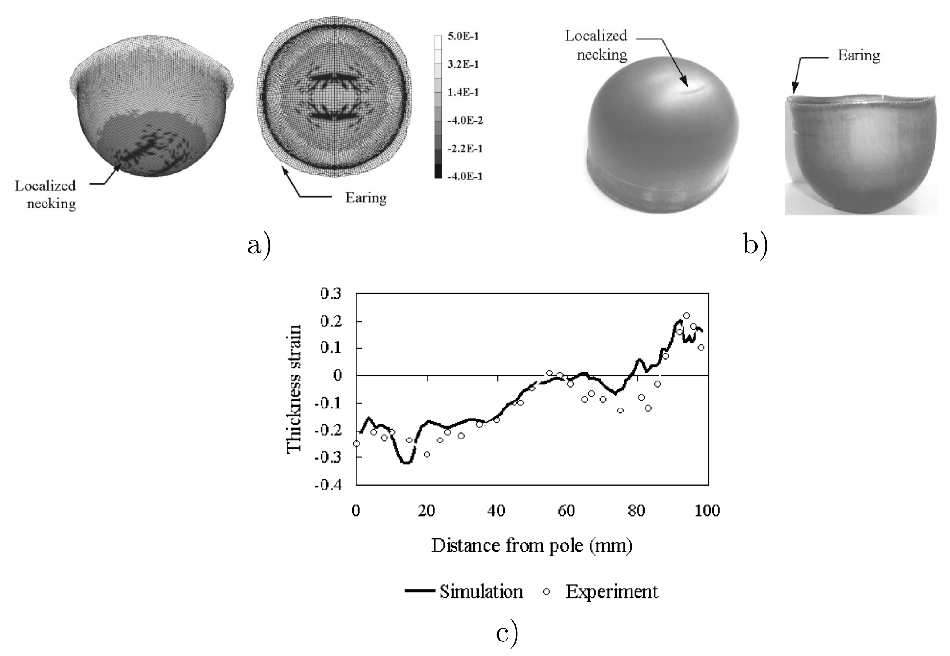
The above formulations have been employed in a wide number of problems where, for example, texture and its evolution may be important. These have been compared to experimental data and to continuum models to show comparatively enhanced predictions. A typical example is a cylindrical cup deep drawing adopted to investigate the texture effects on the localization of the deformations and in earing [172]. In order to do it, the texture components were incorporated into the crystal plasticity model by introducing the measured orientation distribution function (ODF) at each integration point [173]. Three typical crystal orientations { 111 } 110 , { 113 } 110 and { 001 } 110 were selected from the dominant textures in three steel sheets (mild steel Deep-Drawing Quality DDQ dual-phase steel—DP600Ze and high-strength steel CP800). The results obtained from simulations are compared to experimental results. Figure 6 shows the computed results compared with one obtained in experiments for the high-strength steel (CP800) material. The predicted and measured thickness strain distributions (very important in deep drawing), along the rolling direction are similar (see Figure 6c). The thinning of the material appears at the hemispherical bottom region, where a high strain localization can also be observed at the bottom region. Figure 6a,b show the localized necking precluding fracture in numerical and experimental results, respectively. The expected four ears at 45 to the rolling direction are observed. With the fitted simplified texture, the texture component-based crystal model give already results very close to the experimental ones, demonstrating the value of this type of formulations. Furthermore, the results obtained in the study [172] also confirmed that the more the γ fiber texture components, the better is the drawability of bcc steel sheet. The γ fiber also gives rise to four ears at 0 and 90° to rolling direction.
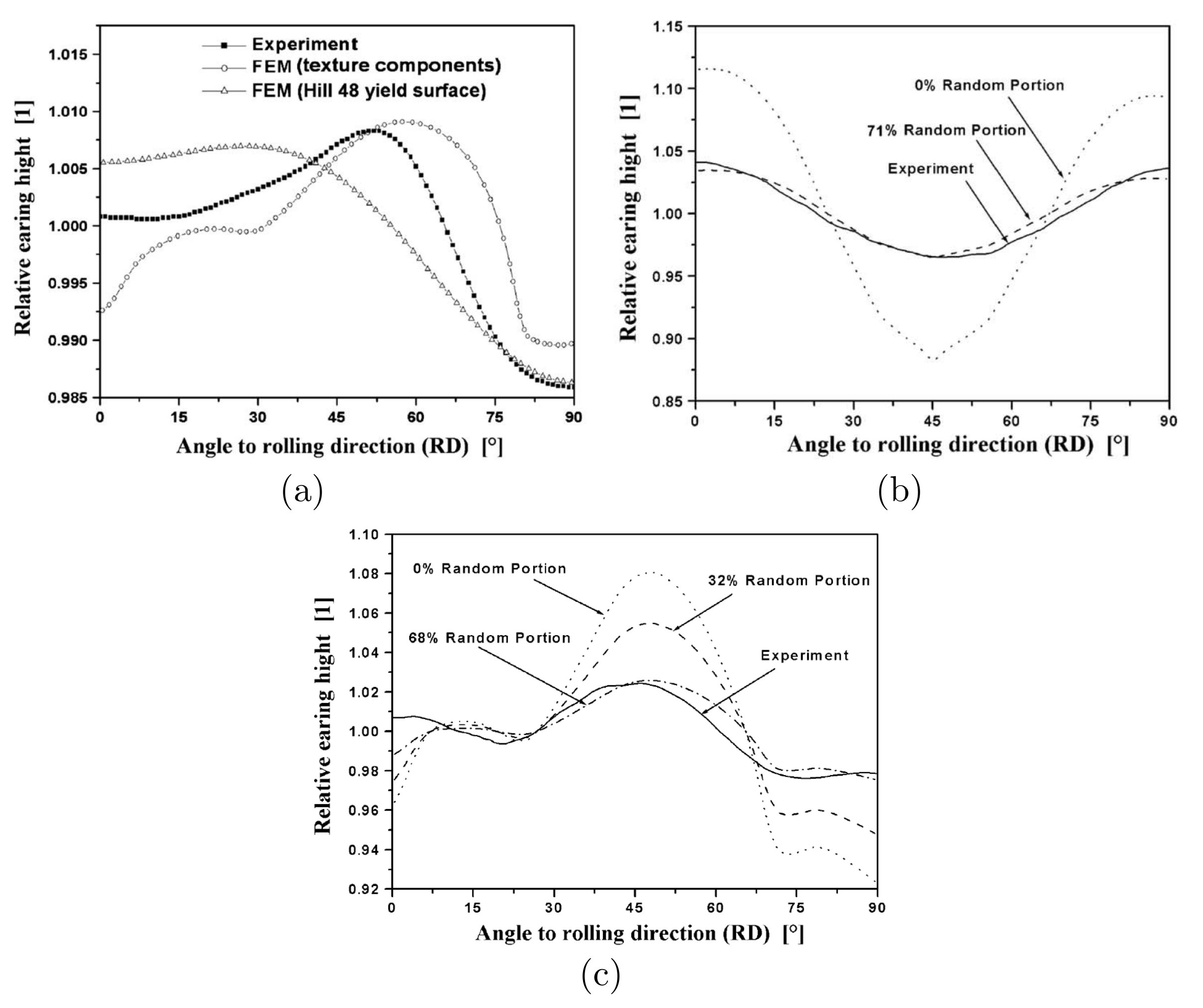
The same simulation benchmark was also employed in [174] but using a new concept for representing textures by mapping small sets of mathematically compact spherical Gaussian texture components on the integration points [175,176,177]. Figure 7 shows the comparison between the computed and experimental results for cube-textured aluminium sheet after cup drawing. In Figure 7a, the result obtained using the texture component-based crystal model is compared with the experiment and also with continuum-based elastoplasticity obtained by use of a Hill-48 yield surface. Two texture components and a random scattering background component are used for fitting the texture component. These results show a better fit of the texture component-based crystal model than that obtained with the classical Hill-based model. Figure 7b,c show simulation results for different approximations using a volume fraction and using two rolling texture components with a random texture component.
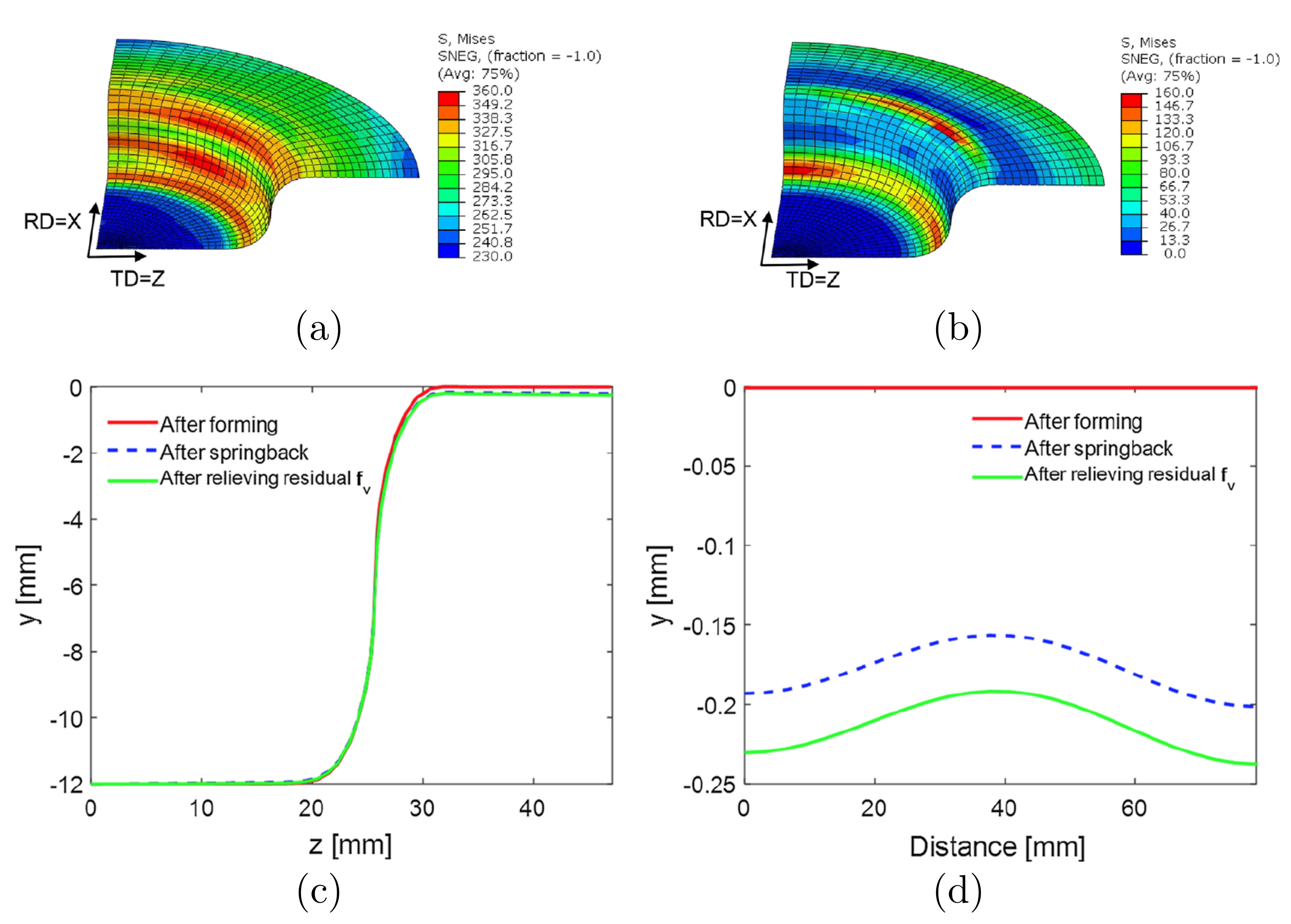
Using the elasto-plastic self-consistent homogenization scheme in the finite element framework, Zecevic and Knezevic [178] explored its potential in simulation and prediction of springback of cup drawing from an AA6022-T4 sheet, see Figure 8; only a quarter is modelled due to symmetries. The springback is obtained by eliminating the contact between the blank and other parts when the punch reaches a travel distance of 12 mm. The von Mises stress contours at the end of drawing and springback are shown in Figure 8a,b, while the dimensional changes are depicted in Figure 8c,d.

5.2. Virtual Material Testing

5.2.1. Texture Evolution

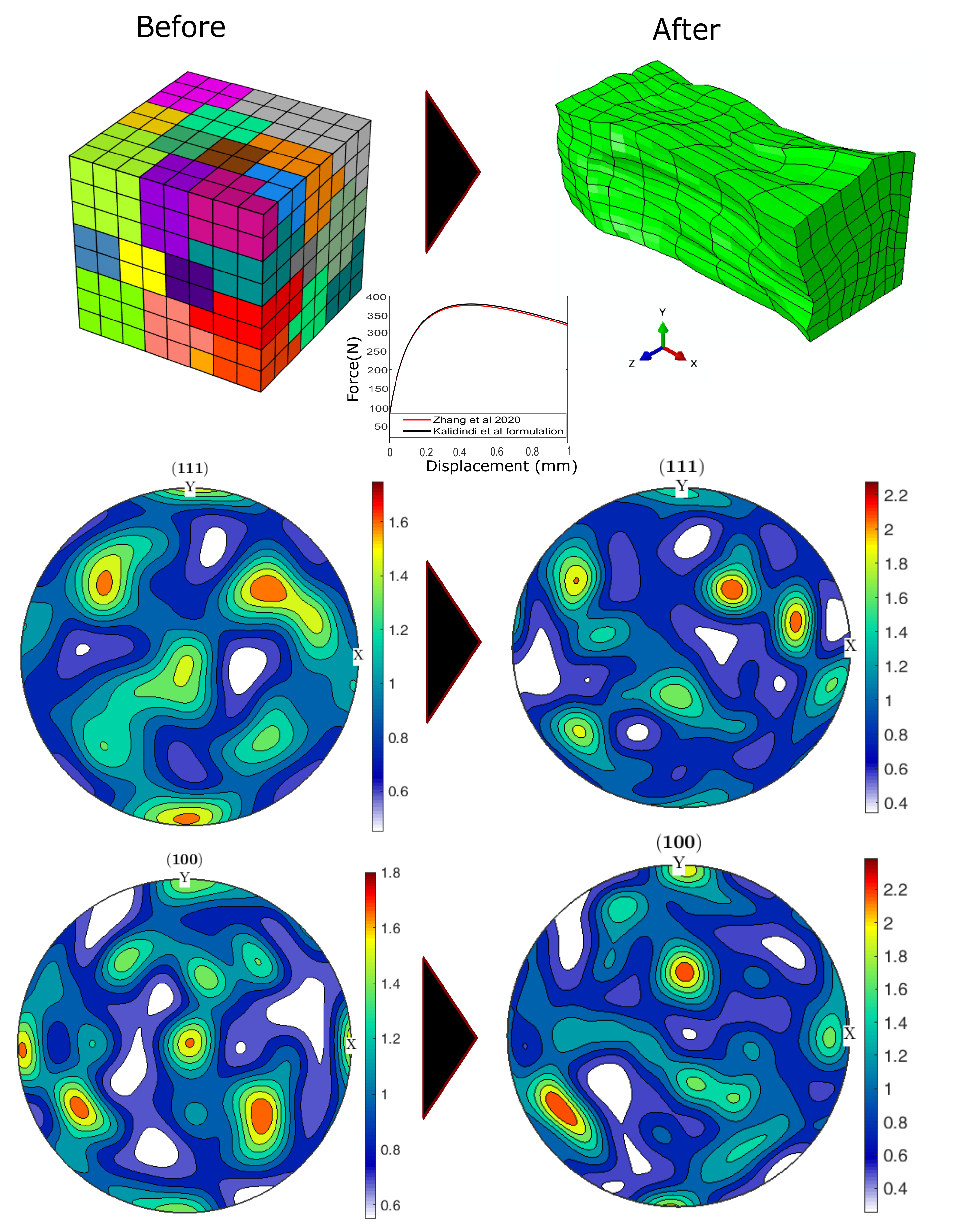
Obviously one of the simulations that can be performed with crystal plasticity models is the analysis of texture evolution and, hence, the evolution of anisotropy. In Figure 9 we show the texture evolution in a copper polycrystal cubic specimen in a tensile test, see full details about the constitutive equations (similar to the avove-presented phenomenological ones) and the material parameters employed in the simulation in [75]. For this simulation we used 512 elements with an initial random texture with 50 orientations. In the same figure, the initial mesh and the deformed mesh is shown. In the middle and lower rows of the figure, the pole figures showing the evolution of texture for directions ( 111 ) (middle row) and ( 100 ) (lower row) are shown. This evolution has been computed in Figure 9 using both the classical Kalidindi et al. framework and the novel framework employing elastic corrector rates, being the results very similar for this case (see again details in [75]).

5.2.2. Impact Test

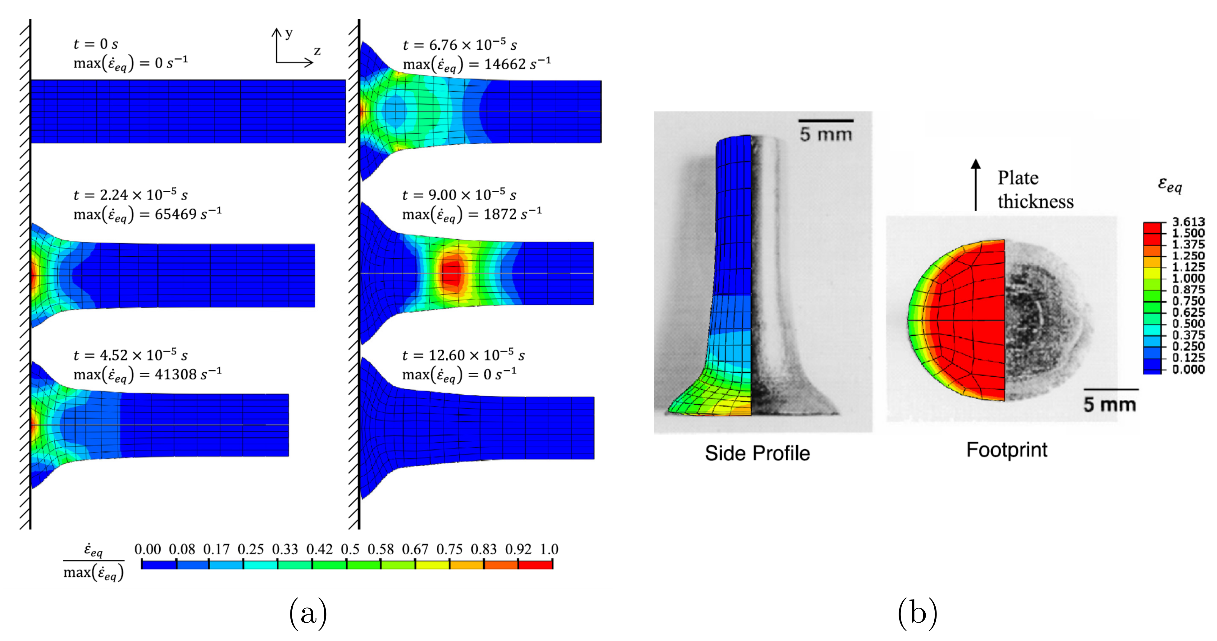
Taylor impact tests were originally devised to obtain the dynamic yield strength of a material at moderate strain rates, but now such tests are used frequently to validate the constitutive model for the simulation of plastic deformation. Figure 10a shows simulations of Ta cylinder by using the viscoplastic self-consistent (VPSC) model in the finite element framework. The simulation was performed by [179] and compared with the experimental results reported in [180,181]. Figure 10a shows the equivalent plastic strain rate contours that develop in the cylinder during the simulation. It can be seen that the dramatic change in the strain rate is observed over the course of simulation. At the beginning of the impact, the highest equivalent plastic strain rate develops at the center of the foot of the cylinder. As the impact progresses, the high strain rate zone moves away from the foot to the other side of the cylinder as a consequence of the plastic wave propagation. The side profile and footprint obtained in the simulation after the impact are compared with the experimental ones and depicted in Figure 10b. The highly heterogeneous plastic deformation is observed at the center of the foot. The deformation in lateral directions is non-uniform as shown in the ellipsoidal shape of the footprint.

5.2.3. Rolling Test

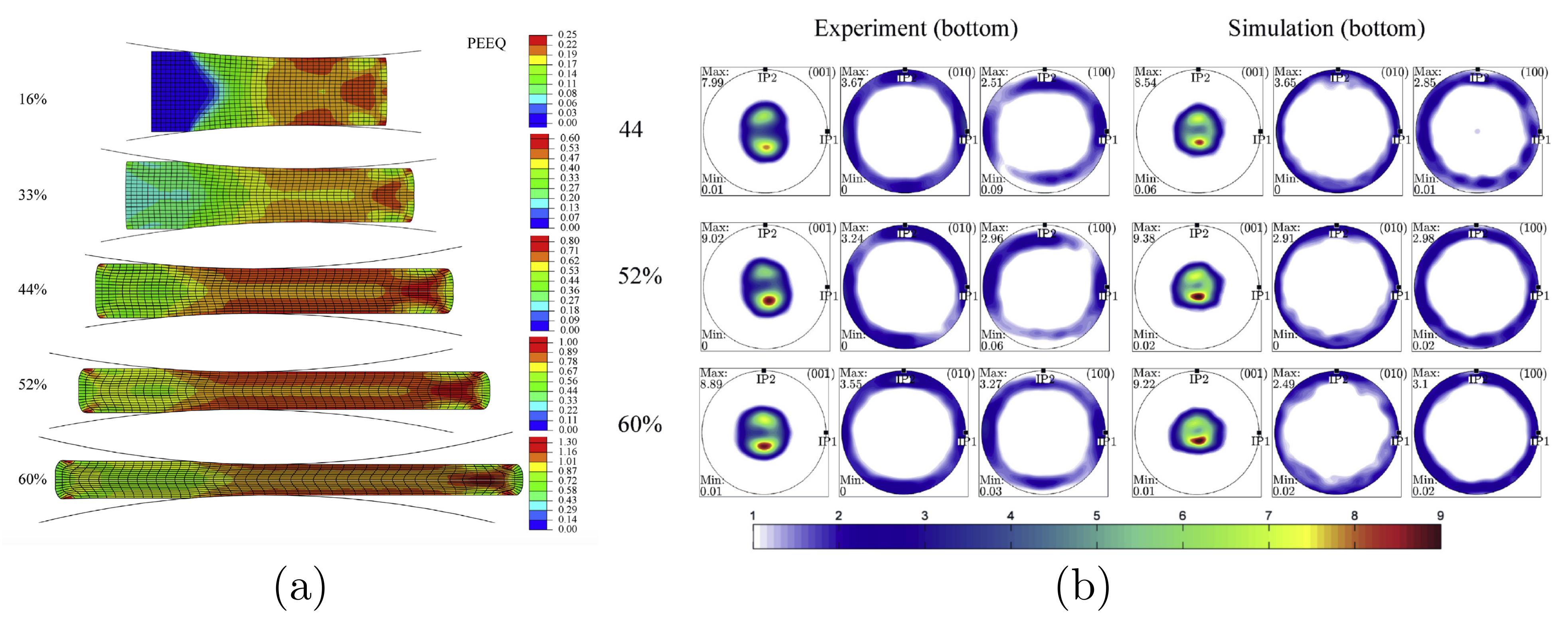
Using the multiscale framework, a typical rolling test is normally carried out to explore the mechanical behavior of polycrystals subjected to non-homogeneous stress states and examine heterogeneous texture development through the thickness of the sample during the process [165,182]. The rolling simulation that has been done in [182] is here recalled. The material of rolling plate is uranium α -U (see [182] for detailed mechanical and texture properties). The initial texture was represented using 1600 individual orientations. Each orientation was assigned to two elements and distributed over their eight integration points. The sample was rolled between two cylinders leading to 60 % reduction in thickness during five steps. The geometry of the rolled plate at each step is depicted in Figure 11a, together with the corresponding contour of the equivalent plastic strain. Due to the highly anisotropic nature of the uranium α -U, the strain is developed heterogeneously through the thickness. Similarly the heterogeneous texture that can be appreciated in Figure 11b. According to [182], the determination of the texture gradients can help with understanding recrystallization kinetics and the final recrystallized microstruture. Consequently, the texture gradients can affect recrystallization by altering crystallographic orientation, grain boundary and dislocation densities.

6. Conclusions

In the 21th century, computational crystal plasticity modelling has achieved a high degree of maturity. Thanks to the current computational power and to the algorithms with increased efficiency as multiscale ones based on the FFT, it is becoming an alternative to classical continuum plasticity for engineering problems. Crystal plasticity simulations allow for incorporating many ingredients of the structure of the material as grain size, dislocations, texture, etc. In this paper we have made an overview of different aspects of the present techniques employed in computational finite element simulations of crystal plasticity, as well as some applications of such simulations.

Author Contributions

Conceptualization, K.N. and F.J.M.; methodology, K.N. and F.J.M.; investigation, K.N., M.Z., V.J.A., M.A.S. and F.J.M.; writing—original draft preparation, K.N., M.Z., V.J.A., M.A.S. and F.J.M.; writing—review and editing, K.N., M.Z., V.J.A., M.A.S. and F.J.M.; funding acquisition, F.J.M. All authors have read and agreed to the published version of the manuscript.

Funding

Partial financial support for this work has been facilitated by Agencia Estatal de Investigación of Spain, Grant No. PGC-2018-097257-B-C32.

Institutional Review Board Statement

Not applicable.

Informed Consent Statement

Not applicable.

Data Availability Statement

Data sharing not applicable.

Conflicts of Interest

The authors declare no conflict of interest. The funders had no role in the design of the study; in the collection, analyses, or interpretation of data; in the writing of the manuscript, or in the decision to publish the results.

References

  1. Wagoner, R.; Chenot, J. Metal Forming Analysis; Cambridge University Press: Cambridge, UK, 2001. [Google Scholar]
  2. Bathe, K.J. Finite Element Procedures, 2nd ed.; Klaus-Jürgen Bathe: Watertown, MA, USA, 2014. [Google Scholar]
  3. Balluffi, R. Introduction to Elasticity Theory for Crystal Deffects; World Scientific: Hackensack, NJ, USA, 2017. [Google Scholar]
  4. Kocks, U.; Tomé, C.; Wenk, H.R. Texture and Anisotropy: Preferred Orientations in Polycrystals and Their Effect on Paterials Properties; Cambridge University Press: Cambridge, UK, 1998. [Google Scholar]
  5. Peirce, D.; Asaro, R.J.; Needleman, A. An analysis of nonuniform and localized deformation in ductile single crystals. Acta Metall. 1982, 30, 1087–1119. [Google Scholar] [CrossRef]
  6. Miehe, C.; Schröder, J.; Schotte, J. Computational homogenization analysis in finite plasticity Simulation of texture development in polycrystalline materials. Comput. Methods Appl. Mech. Eng. 1999, 171, 387–418. [Google Scholar] [CrossRef]
  7. Horstemeyer, M. Integrated Computational Materials Engineering for Metals; Wiley: Hoboken, NJ, USA, 2012. [Google Scholar]
  8. Cuitiño, A.M.; Ortiz, M. Computational modelling of single crystals. Model. Simul. Mater. Sci. Eng. 1992, 1, 225–263. [Google Scholar] [CrossRef] [Green Version]
  9. Fohrmeister, V.; Díaz, G.; Mosler, J. Classic crystal plasticity theory vs crystal plasticity theory based on strong discontinuities. Theoretical and algorithmic aspects. Int. J. Numer. Methods Eng. 2019, 117, 1283–1303. [Google Scholar] [CrossRef]
  10. Kim, J.; Yoon, J. Necking behavior of AA 6022-T4 based on the crystal plasticity and damage models. Int. J. Plast. 2015, 73, 3–23. [Google Scholar] [CrossRef]
  11. Aim, U.; Siddiq, M.; Kartal, M. Representative volume element (RVE) based crystal plasticity study of void growth on phase boundary in titanium alloys. Comput. Mater. Sci. 2019, 161, 346–350. [Google Scholar]
  12. Noell, P.; Carroll, J.; Hattar, K.; Clark, B.; Boyce, B. Do voids nucleate at grain boundaries during ductile rupture? Acta Mater. 2017, 137, 103–114. [Google Scholar] [CrossRef]
  13. Miehe, C.; Welschinger, F.; Hofacker, M. Thermodynamically consistent phase-field models of fracture: Variational principles and multi-field FE implementations. Int. J. Numer. Methods Eng. 2010, 83, 1273–1311. [Google Scholar] [CrossRef]
  14. Grilli, N.; Koslowski, M. The effect of crystal anisotropy and plastic response on the dynamic fracture of energetic materials. J. Appl. Phys. 2019, 126. [Google Scholar] [CrossRef]
  15. Kohlhoff, S.; Gumbsch, P.; Fischmeister, H. Crack propagation in BCC crystals studied with a combined finite-element and atomistic model. Philos. Mag. A 1991, 64, 851–878. [Google Scholar] [CrossRef]
  16. Shilkrot, L.E.; Miller, R.; Curtin, W. Coupled atomistic and discrete dislocation plasticity. Phys. Rev. Lett. 2002, 89, 25501. [Google Scholar] [CrossRef] [PubMed]
  17. Shiari, B.; Miller, R.; Curtin, W. Coupled atomistic/discrete dislocation simulations of nanoindentation at finite temperature. J. Eng. Mater. Technol. 2005, 127, 358–368. [Google Scholar] [CrossRef]
  18. Kochmann, J.; Wulfinghoff, S.; Ehle, L.; Mayer, J.; Svendsen, B.; Reese, S. Efficient and accurate two-scale FE-FFT-based prediction of the effective material behavior of elasto-viscoplastic polycrystals. Comput. Mech. 2018, 61, 751–764. [Google Scholar] [CrossRef]
  19. Valdenaire, P.L.; Le Bouar, Y.; Appolaire, B.; Finel, A. Density-based crystal plasticity: From the discrete to the continuum. Phys. Rev. B 2016, 93, 214111. [Google Scholar] [CrossRef] [Green Version]
  20. Roters, F.; Eisenlohr, P.; Hantcherli, L.; Tjahjanto, D.; Bieler, T.; Raabe, D. Overview of constitutive laws, kinematics, homogenization and multiscale methods in crystal plasticity finite-element modeling: Theory, experiments, applications. Acta Mater. 2010, 58, 1152–1211. [Google Scholar] [CrossRef]
  21. Roters, F.; Eisenlohr, P.; Bieler, T.; Raabe, D. Crystal Plasticity Finite Element Methods in Materials Science and Engineering; Wiley-VHC: Weinheim, Germany, 2010. [Google Scholar]
  22. Zhuang, Z.; Liu, Z.; Cui, Y. Dislocation Mechanism-Based Crystal Plasticity; Academic Press: Cambridge, MA, USA, 2019. [Google Scholar]
  23. Abbaschian, R.; Abbaschian, L.; Reed-Hill, R. Physical Metallurgy Principles; Cengage Learning: Stamford, CT, USA, 2009. [Google Scholar]
  24. Borja, R.I. Plasticity Modeling and Computation; Springer: Berlin, Germany, 2013. [Google Scholar]
  25. Hosford, W.F. The Mechanics of Crystals and Textured Polycrystals; Oxford University Press: Oxford, UK, 1993. [Google Scholar]
  26. Dunne, F.; Petrinic, N. Introduction to Computational Plasticity; Oxford University Press: Oxford, UK, 2005. [Google Scholar]
  27. Hull, D.; Bacon, D. Introduction to Dislocations; Butterworth-Heinemann: Oxford, UK, 2011. [Google Scholar]
  28. Zheng, Z.; Balint, D.; Dunne, F. Rate sensitivity in discrete dislocation plasticity in hexagonal close-packed crystals. Acta Mater. 2016, 107, 17–26. [Google Scholar] [CrossRef] [Green Version]
  29. Testa, G.; Bonora, N.; Ruggiero, A.; Iannitti, G. Flow Stress of bcc Metals over a Wide Range of Temperature and Strain Rates. Metals 2020, 10, 120. [Google Scholar] [CrossRef] [Green Version]
  30. Rogne, B.R.S.; Thaulow, C. Strengthening mechanisms of iron micropillars. Philos. Mag. 2015, 95, 1814–1828. [Google Scholar] [CrossRef]
  31. Hall, E. The Deformation and Ageing of Mild Steel: III Discussion of Results. Proc. Phys. Soc. Sect. B 1951, 64, 747–753. [Google Scholar] [CrossRef]
  32. Petch, N. The Cleavage Strength of Polycrystals. J. Iron Steel Inst. 1953, 174, 25–28. [Google Scholar]
  33. Schmid Erich, W.B. Plasticity of Crystals with Special Reference to Metals; F.A. Hughes: London, UK, 1950. [Google Scholar]
  34. Montáns, F.; Bathe, K. Computational Plasticity; Chapter Towards a Model for Large Strain Anisotropic Elasto-Plasticity; Springer: Berlin, Germany, 2007. [Google Scholar]
  35. Park, S.J.; Han, H.N.; Oh, K.H.; Raabe, D.; Kim, J.K. Finite element simulation of grain interaction and orientation fragmentation during plastic deformation of BCC metals. Mater. Sci. Forum 2002, 408–412, 371–376. [Google Scholar] [CrossRef]
  36. Sachtleber, M.; Zhao, Z.; Raabe, D. Experimental investigation of plastic grain interaction. Mater. Sci. Eng. A 2002, 336, 81–87. [Google Scholar] [CrossRef]
  37. Ma, A.; Roters, F.; Raabe, D. On the consideration of interactions between dislocations and grain boundaries in crystal plasticity finite element modeling—Theory, experiments, and simulations. Acta Mater. 2006, 54, 2181–2194. [Google Scholar] [CrossRef]
  38. Kothari, M.; Anand, L. Elasto-viscoplastic constitutive equations for polycrystalline metals: Application to tantalum. J. Mech. Phys. Solids 1998, 46, 51–67. [Google Scholar] [CrossRef]
  39. Kalidindi, S.; Bronkhorst, C.; Anand, L. Crystallographic texture evolution in bulk deformation processing of FCC metals. J. Mech. Phys. Solids 1992, 40, 537–569. [Google Scholar] [CrossRef]
  40. Kalidindi, S.R. Incorporation of deformation twinning in crystal plasticity models. J. Mech. Phys. Solids 1998, 46, 267–290. [Google Scholar] [CrossRef]
  41. Taylor, G. The mechanism of plastic deformation of crystals. Proc. R. Soc. A 1934, 165, 362–387. [Google Scholar]
  42. Basinski, Z. Thermally activated glide in face-centred cubic metals and its application to the theory of strain hardening. Philos. Mag. 1959, 4, 393–432. [Google Scholar] [CrossRef]
  43. Kuhlmann-Wilsdorf, D. A new theory of workhardening. Trans. Metall. Soc. AIME 1962, 224, 1047–1061. [Google Scholar]
  44. Essmann, U.; Mughrabi, H. Annihilation of dislocations during tensile and cyclic deformation and limits of dislocation densities. Philos. Mag. A 1979, 40, 731–756. [Google Scholar] [CrossRef]
  45. Essmann, U.; Mughrabi, H. Multislip in FCC crystals: A theoretical approach compared with experimental-data. Acta Metall. 1982, 30, 1627–1637. [Google Scholar]
  46. Lavrentev, F.; Pokhil, Y. Relation of dislocation density in different slip systems to work-hardening parameters for magnesium crystals. Mater. Sci. Eng. 1975, 18, 261–270. [Google Scholar] [CrossRef]
  47. Bertin, N.; Tomé, C.; Beyerlein, I.; Barnett, M.; Capolungo, L. On the strength of dislocation interactions and their effect on latent hardening in pure Magnesium. Int. J. Plast. 2014, 62, 72–92. [Google Scholar] [CrossRef]
  48. Arturo Rubio, R.; Haouala, S.; LLorca, J. Grain boundary strengthening of FCC polycrystals. J. Mater. Res. 2019, 34, 2263–2274. [Google Scholar] [CrossRef] [Green Version]
  49. Haouala, S.; Alizadeh, R.; Bieler, T.; Segurado, J.; LLorca, J. Effect of slip transmission at grain boundaries in Al bicrystals. Int. J. Plast. 2020, 126, 102600. [Google Scholar] [CrossRef] [Green Version]
  50. Ma, A.; Hartmaier, A. On the influence of isotropic and kinematic hardening caused by strain gradients on the deformation behaviour of polycrystals. Philos. Mag. 2014, 94, 125–140. [Google Scholar] [CrossRef]
  51. Ma, A.; Hartmaier, A. A study of deformation and phase transformation coupling for TRIP-assisted steels. Int. J. Plast. 2015, 64, 40–55. [Google Scholar] [CrossRef] [Green Version]
  52. Asaro, R.J. Micromechanics of Crystals and Polycrystals. Adv. Appl. Mech. 1983, 23, 1–115. [Google Scholar] [CrossRef]
  53. Lee, E.H. Elastic-Plastic Deformation at Finite Strains. J. Appl. Mech. 1969, 36, 1–6. [Google Scholar] [CrossRef]
  54. Rice, J. Inelastic constitutive relations for solids: An internal-variable theory and its application to metal plasticity. J. Mech. Phys. Solids 1971, 19, 433–455. [Google Scholar] [CrossRef]
  55. Hill, R.; Rice, J.R. Constitutive analysis of elastic-plastic crystals at arbitrary strain. J. Mech. Phys. Solids 1972, 20, 401–413. [Google Scholar] [CrossRef]
  56. Simo, J. Handbook of Numerical Analysis VI; Chapter Numerical Analysis and Simulation of Plasticity; Elsevier: Amsterdam, The Netherlands, 1998; pp. 183–499. [Google Scholar]
  57. Hashiguchi, K. Multiplicative Hyperelastic-Based Plasticity for Finite Elastoplastic Deformation/Sliding: A Comprehensive Review. Arch. Comput. Methods Eng. 2019, 26, 597–637. [Google Scholar] [CrossRef] [Green Version]
  58. Gurtin, M.; Fried, E.; Anand, L. The Mechanics and Thermodynamics of Continua; Cambridge University Press: Cambridge, UK, 2010. [Google Scholar]
  59. Shutov, A.; Pfeiffer, S.; Ihlemann, J. On the simulation of multistage forming processes: Invariance under change of the reference configuration. Mater. Sci. Eng. Technol. 2012, 43, 617–625. [Google Scholar]
  60. Shutov, A.; Ihlemann, J. Analysis of some basic approaches to finite strain elastoplasticity in view of reference change. Int. J. Plast. 2014, 63, 183–197. [Google Scholar] [CrossRef] [Green Version]
  61. Hartley, C.; Mishin, Y. Characterization and visualization of the lattice misfit associated with dislocation cores. Acta Mater. 2005, 53, 1313–1321. [Google Scholar] [CrossRef]
  62. Nye, J.F. Some geometrical relations in dislocated crystals. Acta Metall. 1953, 1, 153–162. [Google Scholar] [CrossRef]
  63. Kröner, E. Benefits and shortcomings of the continuous theory of dislocations. Int. J. Solids Struct. 2001, 38, 1115–1134. [Google Scholar] [CrossRef]
  64. Forest, S.; Barbe, F.; Cailletaud, G. Cosserat modelling of size effects in the mechanical behaviour of polycrystals and multi-phase materials. Int. J. Solids Struct. 2000, 37, 7105–7126. [Google Scholar] [CrossRef]
  65. Gurtin, M.E. A gradient theory of single-crystal viscoplasticity that accounts for geometrically necessary dislocations. J. Mech. Phys. Solids 2002, 50, 5–32. [Google Scholar] [CrossRef]
  66. Evers, L.P.; Brekelmans, W.A.; Geers, M.G. Scale dependent crystal plasticity framework with dislocation density and grain boundary effects. Int. J. Solids Struct. 2004, 41, 5209–5230. [Google Scholar] [CrossRef]
  67. Evers, L.P.; Brekelmans, W.A.; Geers, M.G. Non-local crystal plasticity model with intrinsic SSD and GND effects. J. Mech. Phys. Solids 2004, 52, 2379–2401. [Google Scholar] [CrossRef]
  68. Ma, A.; Roters, F. A constitutive model for fcc single crystals based on dislocation densities and its application to uniaxial compression of aluminium single crystals. Acta Mater. 2004, 52, 3603–3612. [Google Scholar] [CrossRef]
  69. Han, C.S.; Gao, H.; Huang, Y.; Nix, W.D. Mechanism-based strain gradient crystal plasticity—I. Theory. J. Mech. Phys. Solids 2005, 53, 1188–1203. [Google Scholar] [CrossRef]
  70. Kuroda, M.; Tvergaard, V. Studies of scale dependent crystal viscoplasticity models. J. Mech. Phys. Solids 2006, 54, 1789–1810. [Google Scholar] [CrossRef]
  71. Gurtin, M.E.; Anand, L.; Lele, S.P. Gradient single-crystal plasticity with free energy dependent on dislocation densities. J. Mech. Phys. Solids 2007, 55, 1853–1878. [Google Scholar] [CrossRef]
  72. Gurtin, M.E. A finite-deformation, gradient theory of single-crystal plasticity with free energy dependent on densities of geometrically necessary dislocations. Int. J. Plast. 2008, 24, 702–725. [Google Scholar] [CrossRef]
  73. Kuroda, M.; Tvergaard, V. On the formulations of higher-order strain gradient crystal plasticity models. J. Mech. Phys. Solids 2008, 56, 1591–1608. [Google Scholar] [CrossRef]
  74. Grilli, N.; Koslowski, M. The effect of crystal orientation on shock loading of single crystal energetic materials. Comput. Mater. Sci. 2018, 155, 235–245. [Google Scholar] [CrossRef]
  75. Zhang, M.; Nguyen, K.; Segurado, J.; Montáns, F. A multiplicative finite strain crystal plasticity formulation based on additive elastic corrector rates: Theory and numerical implementation. Int. J. Plast. 2020, 137, 102899. [Google Scholar] [CrossRef]
  76. Latorre, M.; Montáns, F. A new class of plastic flow evolution equations for anisotropic multiplicative elastoplasticity based on the notion of a corrector elastic strain rate. Appl. Math. Model. 2018, 55, 716–740. [Google Scholar] [CrossRef] [Green Version]
  77. Zhang, M.; Montáns, F. A simple formulation for large-strain cyclic hyperelasto-plasticity using elastic correctors. Theory and algorithmic implementation. Int. J. Plast. 2019, 113, 185–217. [Google Scholar] [CrossRef]
  78. Nguyen, K.; Sanz, M.A.; Montáns, F. Plane-stress constrained multiplicative hyperelasto-plasticity with nonlinear kinematic hardening. Consistent theory based on elastic corrector rates and algorithmic implementation. Int. J. Plast. 2020, 128, 102592. [Google Scholar] [CrossRef]
  79. Caminero, M.; Montáns, F.; Bathe, K.J. Modeling large strain anisotropic elasto-plasticity with logarithmic strain and stress measures. Comput. Struct. 2011, 89, 826–843. [Google Scholar] [CrossRef]
  80. Sánz, M.; Montáns, F.; Latorre, M. Computational anisotropic hardening multiplicative elastoplasticity based on the corrector elastic logarithmic strain rate. Comput. Methods Appl. Mech. Eng. 2017, 320, 82–121. [Google Scholar] [CrossRef] [Green Version]
  81. Latorre, M.; Montáns, F. Stress and strain mapping tensors and general work-conjugacy in large strain continuum mechanics. Appl. Math. Model. 2016, 40, 3938–3950. [Google Scholar] [CrossRef]
  82. Peirce, D.; Asaro, R.J.; Needleman, A. Material rate dependence and localized deformation in crystalline solids. Acta Metall. 1983, 31, 1951–1976. [Google Scholar] [CrossRef]
  83. Needleman, A.; Asaro, R.J.; Lemonds, J.; Peirce, D. Finite element analysis of crystalline solids. Comput. Methods Appl. Mech. Eng. 1985, 52, 689–708. [Google Scholar] [CrossRef]
  84. Fivel, M.; Tabourot, L.; Rauch, E.; Canova, G. Identification through mesoscopic simulations of macroscopic parameters of physically based constitutive equations for the plastic behavior of FCC single crystals. J. Phys. IV 1998, 8, 151–158. [Google Scholar]
  85. Groh, S.; Maron, E.; Horstemeyer, M.; Zbib, H. Multiscale modeling of the plasticity in an aluminum single crystal. Int. J. Plast. 2009, 25, 1456–1473. [Google Scholar] [CrossRef]
  86. Meric, L.; Poubanne, P.; Cailletaud, G. Single Crystal Modeling for Structural Calculations: Part 1—Model Presentation. J. Eng. Mater. Technol. 1991, 113, 162–170. [Google Scholar] [CrossRef]
  87. Cailletaud, G. A micromechanical approach to inelastic behaviour of metals. Int. J. Plast. 1992, 8, 55–73. [Google Scholar] [CrossRef]
  88. Hu, Z.; Rauch, E.F.; Teodosiu, C. Work-hardening behavior of mild steel under stress reversal at large strains. Int. J. Plast. 1992, 8, 839–856. [Google Scholar] [CrossRef]
  89. Hasija, V.; Ghosh, S.; Mills, M.J.; Joseph, D.S. Deformation and creep modeling in polycrystalline Ti-6Al alloys. Acta Mater. 2003, 51, 4533–4549. [Google Scholar] [CrossRef]
  90. Venkatramani, G.; Ghosh, S.; Mills, M. A size-dependent crystal plasticity finite-element model for creep and load shedding in polycrystalline titanium alloys. Acta Mater. 2007, 55, 3971–3986. [Google Scholar] [CrossRef]
  91. Cruzado, A.; LLorca, J.; Segurado, J. Modeling cyclic deformation of inconel 718 superalloy by means of crystal plasticity and computational homogenization. Int. J. Solids Struct. 2017, 122–123, 148–161. [Google Scholar] [CrossRef]
  92. Tome, C.; Canova, G.R.; Kocks, U.F.; Christodoulou, N.; Jonas, J.J. The relation between macroscopic and microscopic strain hardening in F.C.C. polycrystals. Acta Metall. 1984, 32, 1637–1653. [Google Scholar] [CrossRef]
  93. Bassani, J.L.; Wu, T.Y. Latent hardening in single crystals. II. Analytical characterization and predictions. Proc. R. Soc. Lond. Ser. A Math. Phys. Sci. 1991, 435, 21–41. [Google Scholar] [CrossRef]
  94. Polmear, I.J. From Traditional Alloys to Nanocrystals; Butterworth-Heinemann: Burlington, MA, USA, 2006. [Google Scholar]
  95. Estrin, Y.; Mecking, H. A unified phenomenological description of work hardening and creep based on one-parameter models. Acta Metall. 1984, 32, 57–70. [Google Scholar] [CrossRef]
  96. Estrin, Y. Dislocation-Density–Related Constitutive Modeling. In Unified Constitutive Laws of Plastic Deformation; Krausz, A., Krausz, K., Eds.; Academic Press: Cambridge, MA, USA, 1996; pp. 69–106. [Google Scholar] [CrossRef]
  97. Mecking, H.; Kocks, U.F. Kinetics of flow and strain-hardening. Acta Metall. 1981, 29, 1865–1875. [Google Scholar] [CrossRef]
  98. Devincre, B.; Hoc, T.; Kubin, L. Dislocation mean free paths and strain hardening of crystals. Science 2008, 320, 1745–1748. [Google Scholar] [CrossRef]
  99. Cheong, K.S.; Busso, E.P. Discrete dislocation density modelling of single phase FCC polycrystal aggregates. Acta Mater. 2004, 52, 5665–5675. [Google Scholar] [CrossRef]
  100. De Sansal, C.; Devincre, B.; Kubin, L. Grain size strengthening in microcrystalline copper: A three-dimensional dislocation dynamics simulation. Key Eng. Mater. 2010, 423, 25–32. [Google Scholar] [CrossRef]
  101. Estrin, Y.; Kubin, L.P. Local strain hardening and nonuniformity of plastic deformation. Acta Metall. 1986, 34, 2455–2464. [Google Scholar] [CrossRef]
  102. Kameda, T.; Zikry, M.A. Three dimensional dislocation-based crystalline constitutive formulation for ordered intermetallics. Scr. Mater. 1998, 38, 631–636. [Google Scholar] [CrossRef]
  103. Rezvanian, O.; Zikry, M.A.; Rajendran, A.M. Statistically stored, geometrically necessary and grain boundary dislocation densities: Microstructural representation and modelling. Proc. R. Soc. A Math. Phys. Eng. Sci. 2007, 463, 2833–2853. [Google Scholar] [CrossRef]
  104. Shi, J.; Zikry, M.A. Grain-boundary interactions and orientation effects on crack behavior in polycrystalline aggregates. Int. J. Solids Struct. 2009, 46, 3914–3925. [Google Scholar] [CrossRef] [Green Version]
  105. Shanthraj, P.; Zikry, M.A. Dislocation density evolution and interactions in crystalline materials. Acta Mater. 2011, 59, 7695–7702. [Google Scholar] [CrossRef]
  106. Orowan, E. Zur Kristallplastizität. I: Tieftemperaturplastizität und Beckersche Formel. Z. Phys. 1934, 89, 605–613. [Google Scholar] [CrossRef]
  107. Kocks, U. Thermodynamics and Kinetics of Slip, Volume 19 of Progress in Materials Science; Pergamon Press: Oxford, UK, 2003. [Google Scholar]
  108. Rodríguez-Galán, D.; Sabirov, I.; Segurado, J. Temperature and stain rate effect on the deformation of nanostructured pure titanium. Int. J. Plast. 2015, 70, 191–205. [Google Scholar] [CrossRef]
  109. Shahba, A.; Ghosh, S. Crystal plasticity FE modeling of Ti alloys for a range of strain-rates. Part I: A unified constitutive model and flow rule. Int. J. Plast. 2016, 87, 48–68. [Google Scholar] [CrossRef]
  110. Cailard, D.; Martin, J. Thermally Activated Mechanisms in Crystal Plasticity; Elsevier: Amsterdam, The Netherlands, 2003. [Google Scholar]
  111. Taylor, G.I. Plastic strain in metals. J. Inst. Met. 1938, 62, 307–324. [Google Scholar]
  112. Elkhodary, K.; Lee, W.; Sun, L.P.; Brenner, D.W.; Zikry, M.A. Deformation mechanisms of an Ω precipitate in a high-strength aluminum alloy subjected to high strain rates. J. Mater. Res. 2011, 26, 487–497. [Google Scholar] [CrossRef]
  113. Stelmashenko, N.A.; Walls, M.G.; Brown, L.M.; Milman, Y.V. Microindentations on W and Mo oriented single crystals: An STM study. Acta Metall. Mater. 1993, 41, 2855–2865. [Google Scholar] [CrossRef]
  114. Wang, Y.; Raabe, D.; Klüber, C.; Roters, F. Orientation dependence of nanoindentation pile-up patterns and of nanoindentation microtextures in copper single crystals. Acta Mater. 2004, 52, 2229–2238. [Google Scholar] [CrossRef] [Green Version]
  115. Zaafarani, N.; Raabe, D.; Singh, R.N.; Roters, F.; Zaefferer, S. Three-dimensional investigation of the texture and microstructure below a nanoindent in a Cu single crystal using 3D EBSD and crystal plasticity finite element simulations. Acta Mater. 2006, 54, 1863–1876. [Google Scholar] [CrossRef]
  116. Zaafarani, N.; Raabe, D.; Roters, F.; Zaefferer, S. On the origin of deformation-induced rotation patterns below nanoindents. Acta Mater. 2008, 56, 31–42. [Google Scholar] [CrossRef] [Green Version]
  117. Sánchez-Martín, R.; Pérez-Prado, M.T.; Segurado, J.; Bohlen, J.; Gutiérrez-Urrutia, I.; Llorca, J.; Molina-Aldareguia, J.M. Measuring the critical resolved shear stresses in Mg alloys by instrumented nanoindentation. Acta Mater. 2014, 71, 283–292. [Google Scholar] [CrossRef] [Green Version]
  118. Motz, C.; Schöberl, T.; Pippan, R. Mechanical properties of micro-sized copper bending beams machined by the focused ion beam technique. Acta Mater. 2005, 53, 4269–4279. [Google Scholar] [CrossRef]
  119. Weber, F.; Schestaknow, I.; Roters, F.; Raabe, D. Texture Evolution During Bending of a Single Crystal Copper Nanowire Studied by EBSD and Crystal Plasticity Finite Element Simulations. Adv. Eng. Mater. 2008, 10, 737–741. [Google Scholar] [CrossRef]
  120. Kiener, D.; Grosinger, W.; Dehm, G.; Pippan, R. A further step towards an understanding of size-dependent crystal plasticity: In situ tension experiments of miniaturized single-crystal copper samples. Acta Mater. 2008, 56, 580–592. [Google Scholar] [CrossRef]
  121. Gong, J.; Wilkinson, A.J. A microcantilever investigation of size effect, solid-solution strengthening and second-phase strengthening for a prism slip in alpha-Ti. Acta Mater. 2011, 59, 5970–5981. [Google Scholar] [CrossRef]
  122. Zhou, C.; Beyerlein, I.J.; Lesar, R. Plastic deformation mechanisms of fcc single crystals at small scales. Acta Mater. 2011, 59, 7673–7682. [Google Scholar] [CrossRef]
  123. Norton, A.D.; Falco, S.; Young, N.; Severs, J.; Todd, R.I. Microcantilever investigation of fracture toughness and subcritical crack growth on the scale of the microstructure in Al2O3. J. Eur. Ceram. Soc. 2015, 35, 4521–4533. [Google Scholar] [CrossRef]
  124. Raabe, D.; Ma, D.; Roters, F. Effects of initial orientation, sample geometry and friction on anisotropy and crystallographic orientation changes in single crystal microcompression deformation: A crystal plasticity finite element study. Acta Mater. 2007, 55, 4567–4583. [Google Scholar] [CrossRef]
  125. Ashby, M.F. The deformation of plastically non-homogeneous materials. Philos. Mag. 1970, 21, 399–424. [Google Scholar] [CrossRef]
  126. Evers, L.P.; Parks, D.M.; Brekelmans, W.A.; Geers, M.G. Crystal plasticity model with enhanced hardening by geometrically necessary dislocation accumulation. J. Mech. Phys. Solids 2002, 50, 2403–2424. [Google Scholar] [CrossRef]
  127. Gao, H.; Huang, Y. Geometrically necessary dislocation and size-dependent plasticity. Scr. Mater. 2003, 48, 113–118. [Google Scholar] [CrossRef]
  128. Kuroda, M. Plasticity and Beyond: Microstructures, Crystal-Plasticity and Phase Transitions; Chapter on Scale-Dependent Crystal Plasticity Models; CSIM Courses and Lectures; Springer: Berlin, Germany, 2014. [Google Scholar]
  129. Fleck, N.A.; Muller, G.M.; Ashby, M.F.; Hutchinson, J.W. Strain gradient plasticity: Theory and experiment. Acta Metall. Mater. 1994, 42, 475–487. [Google Scholar] [CrossRef]
  130. Gao, H.; Huang, Y.; Nix, W.D.; Hutchinson, J.W. Mechanism-based strain gradient plasticity—I. Theory. J. Mech. Phys. Solids 1999, 47, 1239–1263. [Google Scholar] [CrossRef]
  131. Cheong, K.S.; Busso, E.P.; Arsenlis, A. A study of microstructural length scale effects on the behaviour of FCC polycrystals using strain gradient concepts. Int. J. Plast. 2005, 21, 1797–1814. [Google Scholar] [CrossRef] [Green Version]
  132. Busso, E.P.; Meissonnier, F.T.; O’Dowd, N.P. Gradient-dependent deformation of two-phase single crystals. J. Mech. Phys. Solids 2000, 48, 2333–2361. [Google Scholar] [CrossRef]
  133. Dunne, F.P.; Rugg, D.; Walker, A. Lengthscale-dependent, elastically anisotropic, physically-based hcp crystal plasticity: Application to cold-dwell fatigue in Ti alloys. Int. J. Plast. 2007, 23, 1061–1083. [Google Scholar] [CrossRef]
  134. Han, C.S.; Ma, A.; Roters, F.; Raabe, D. A Finite Element approach with patch projection for strain gradient plasticity formulations. Int. J. Plast. 2007, 23, 690–710. [Google Scholar] [CrossRef]
  135. Gurtin, M.E.; Needleman, A. Boundary conditions in small-deformation, single-crystal plasticity that account for the Burgers vector. J. Mech. Phys. Solids 2005, 53, 1–31. [Google Scholar] [CrossRef] [Green Version]
  136. Yefimov, S.; Van Der Giessen, E.; Groma, I. Bending of a single crystal: Discrete dislocation and nonlocal crystal plasticity simulations. Model. Simul. Mater. Sci. Eng. 2004, 12, 1069–1086. [Google Scholar] [CrossRef]
  137. Bardella, L. A deformation theory of strain gradient crystal plasticity that accounts for geometrically necessary dislocations. J. Mech. Phys. Solids 2006, 54, 128–160. [Google Scholar] [CrossRef]
  138. Bayley, C.J.; Brekelmans, W.A.; Geers, M.G. A comparison of dislocation induced back stress formulations in strain gradient crystal plasticity. Int. J. Solids Struct. 2006, 43, 7268–7286. [Google Scholar] [CrossRef] [Green Version]
  139. Borg, U.; Niordson, C.F.; Kysar, J.W. Size effects on void growth in single crystals with distributed voids. Int. J. Plast. 2008, 24, 688–701. [Google Scholar] [CrossRef]
  140. Bardella, L.; Segurado, J.; Panteghini, A.; Llorca, J. Latent hardening size effect in small-scale plasticity. Model. Simul. Mater. Sci. Eng. 2013, 21. [Google Scholar] [CrossRef] [Green Version]
  141. Niordson, C.F.; Kysar, J.W. Computational strain gradient crystal plasticity. J. Mech. Phys. Solids 2014, 62, 31–47. [Google Scholar] [CrossRef]
  142. Sandfeld, S.; Hochrainer, T.; Gumbsch, P.; Zaiser, M. Numerical implementation of a 3D continuum theory of dislocation dynamics and application to micro-bending. Philos. Mag. 2010, 90, 3697–3728. [Google Scholar] [CrossRef]
  143. Groma, I. Link between the microscopic and mesoscopic length-scale description of the collective behavior of dislocations. Phys. Rev. B Condens. Matter Mater. Phys. 1997, 56, 5807–5813. [Google Scholar] [CrossRef] [Green Version]
  144. El-Azab, A. Statistical mechanics treatment of the evolution of dislocation distributions in single crystals. Phys. Rev. B Condens. Matter Mater. Phys. 2000, 61, 11956–11966. [Google Scholar] [CrossRef]
  145. Acharya, A. A model of crystal plasticity based on the theory of continuously distributed dislocations. J. Mech. Phys. Solids 2001, 49, 761–784. [Google Scholar] [CrossRef]
  146. Acharya, A.; Roy, A. Size effects and idealized dislocation microstructure at small scales: Predictions of a Phenomenological model of Mesoscopic Field Dislocation Mechanics: Part I. J. Mech. Phys. Solids 2006, 54, 1687–1710. [Google Scholar] [CrossRef] [Green Version]
  147. Hochrainer, T.; Zaiser, M.; Gumbsch, P. A three-dimensional continuum theory of dislocation systems: Kinematics and mean-field formulation. Philos. Mag. 2007, 87, 1261–1282. [Google Scholar] [CrossRef]
  148. Hochrainer, T.; Zaiser, M.; Gumbsch, P. Dislocation transport and line length increase in averaged descriptions of dislocations. AIP Conf. Proc. 2009, 1168, 1133–1136. [Google Scholar] [CrossRef] [Green Version]
  149. Xia, S.X.; El-Azab, A. A preliminary investigation of dislocation cell structure formation in metals using continuum dislocation dynamics. IOP Conf. Ser. Mater. Sci. Eng. 2015, 89. [Google Scholar] [CrossRef] [Green Version]
  150. Hochrainer, T. Thermodynamically consistent continuum dislocation dynamics. J. Mech. Phys. Solids 2016, 88, 12–22. [Google Scholar] [CrossRef] [Green Version]
  151. Sarma, G.; Zacharia, T. Integration algorithm for modeling the elasto-viscoplastic response of polycrystalline materials. J. Mech. Phys. Solids 1999, 47, 1219–1238. [Google Scholar] [CrossRef]
  152. Maniatty, A.; Dawson, P.; Lee, Y. A time integration algorithm for elasto-viscoplastic cubic crystals applied to modelling polycrystalline deformation. Int. J. Numer. Methods Eng. 1992, 35, 1565–1588. [Google Scholar] [CrossRef]
  153. Roters, F.; Diehl, M.; Shanthraj, P.; Eisenlohr, P.; Reuber, C.; Wong, S.L.; Maiti, T.; Ebrahimi, A.; Hochrainer, T.; Fabritius, H.O.; et al. DAMASK: The Düsseldorf Advanced Material Simulation Kit for modeling multi-physics crystal plasticity, thermal, and damage phenomena from the single crystal up to the component scale. Comput. Mater. Sci. 2019, 158, 420–478. [Google Scholar] [CrossRef]
  154. Arsenlis, A.; Parks, D.M.; Becker, R.; Bulatov, V.V. On the evolution of crystallographic dislocation density in non-homogeneously deforming crystals. J. Mech. Phys. Solids 2004, 52, 1213–1246. [Google Scholar] [CrossRef]
  155. Borja, R.I.; Wren, J.R. Discrete micromechanics of elastoplastic crystals. Int. J. Numer. Methods Eng. 1993, 36, 3815–3840. [Google Scholar] [CrossRef]
  156. Miehe, C. Exponential map algorithm for stress updates in anisotropic multiplicative elastoplasticity for single crystals. Int. J. Numer. Methods Eng. 1996, 39, 3367–3390. [Google Scholar] [CrossRef]
  157. Asaro, R.; Needleman, A. Texture development and strain hardening in rate dependent polycrystals. Acta Metall. 1985, 33, 923–953. [Google Scholar] [CrossRef]
  158. Castañeda, P.P. The effective mechanical properties of nonlinear isotropic composites. J. Mech. Phys. Solids 1991, 39, 45–71. [Google Scholar] [CrossRef]
  159. Lebensohn, R.A.; Tomé, C.N. A self-consistent anisotropic approach for the simulation of plastic deformation and texture development of polycrystals: Application to zirconium alloys. Acta Metall. Mater. 1993, 41, 2611–2624. [Google Scholar] [CrossRef]
  160. Lebensohn, R.; Uhlenhut, H.; Hartig, C.; Mecking, H. Plastic flow of γ-TiAl-Based polysynthetically twinned crystals: Micromechanical modeling and experimental validation. Acta Mater. 1998, 46, 4701–4709. [Google Scholar] [CrossRef]
  161. Masson, R.; Bornert, M.; Suquet, P.; Zaoui, A. Affine formulation for the prediction of the effective properties of nonlinear composites and polycrystals. J. Mech. Phys. Solids 2000, 48, 1203–1227. [Google Scholar] [CrossRef] [Green Version]
  162. Lebensohn, R.A.; Tomé, C.N.; Castañeda, P.P. Self-consistent modelling of the mechanical behaviour of viscoplastic polycrystals incorporating intragranular field fluctuations. Philos. Mag. 2007, 87, 4287–4322. [Google Scholar] [CrossRef]
  163. Bellec, V.; Bøe, R.; Rise, L.; Thorsnes, T. Influence of bottom currents on the Lofoten continental margin, North Norway. Rend. Online Soc. Geol. Ital. 2009, 7, 155–157. [Google Scholar]
  164. Lebensohn, R.A.; Zecevic, M.; Knezevic, M.; McCabe, R.J. Average intragranular misorientation trends in polycrystalline materials predicted by a viscoplastic self-consistent approach. Acta Mater. 2016, 104, 228–236. [Google Scholar] [CrossRef] [Green Version]
  165. Segurado, J.; Lebensohn, R.A.; Llorca, J.; Tomé, C.N. Multiscale modeling of plasticity based on embedding the viscoplastic self-consistent formulation in implicit finite elements. Int. J. Plast. 2012, 28, 124–140. [Google Scholar] [CrossRef]
  166. Knezevic, M.; Crapps, J.; Beyerlein, I.J.; Coughlin, D.R.; Clarke, K.D.; McCabe, R.J. Anisotropic modeling of structural components using embedded crystal plasticity constructive laws within finite elements. Int. J. Mech. Sci. 2016, 105, 227–238. [Google Scholar] [CrossRef] [Green Version]
  167. Zecevic, M.; Beyerlein, I.J.; Knezevic, M. Coupling elasto-plastic self-consistent crystal plasticity and implicit finite elements: Applications to compression, cyclic tension-compression, and bending to large strains. Int. J. Plast. 2017, 93, 187–211. [Google Scholar] [CrossRef]
  168. Knezevic, M.; Beyerlein, I.J. Multiscale Modeling of Microstructure-Property Relationships of Polycrystalline Metals during Thermo-Mechanical Deformation. Adv. Eng. Mater. 2018, 1700956, 1–19. [Google Scholar] [CrossRef]
  169. Borja, R.I.; Rahmani, H. Discrete micromechanics of elastoplastic crystals in the finite deformation range. Comput. Methods Appl. Mech. Eng. 2014, 275, 234–263. [Google Scholar] [CrossRef]
  170. Miehe, C. Multisurface thermoplasticity for single crystals at large strains in terms of Eulerian vector updates. Int. J. Solids Struct. 1996, 33, 3103–3130. [Google Scholar] [CrossRef]
  171. Weber, G.; Anand, L. Finite deformation constitutive equations and a time integration procedure for isotropic, hyperelastic-viscoplastic solids. Comput. Methods Appl. Mech. Eng. 1990, 79, 173–202. [Google Scholar] [CrossRef]
  172. Nakamachi, E.; Xie, C.L.; Harimoto, M. Drawability assessment of BCC steel sheet by using elastic/crystalline viscoplastic finite element analyses. Int. J. Mech. Sci. 2001, 43, 631–652. [Google Scholar] [CrossRef]
  173. Helming, K.; Eschner, T. A new approach to texture analysis of multiphase materials using a texture component model. Cryst. Res. Technol. 1990, 25, K203–K208. [Google Scholar] [CrossRef]
  174. Raabe, D.; Roters, F. Using texture components in crystal plasticity finite element simulations. Int. J. Plast. 2004, 20, 339–361. [Google Scholar] [CrossRef]
  175. Zhao, Z.; Roters, F.; Mao, W.; Raabe, D. Introduction of a texture component crystal plasticity finite element method for anisotropy simulations. Adv. Eng. Mater. 2001, 3, 984–990. [Google Scholar] [CrossRef]
  176. Raabe, D.; Zhao, Z.; Roters, F. A finite element method on the basis of texture components for fast predictions of anisotropic forming operations. Steel Res. 2001, 72, 421–426. [Google Scholar] [CrossRef]
  177. Raabe, D.; Sachtleber, M.; Zhao, Z.; Roters, F.; Zaefferer, S. Micromechanical and macromechanical effects in grain scale polycrystal plasticity experimentation and simulation. Acta Mater. 2001, 49, 3433–3441. [Google Scholar] [CrossRef]
  178. Zecevic, M.; Knezevic, M. Modeling of Sheet Metal Forming Based on Implicit Embedding of the Elasto-Plastic Self-Consistent Formulation in Shell Elements: Application to Cup Drawing of AA6022-T4. JOM 2017, 69, 922–929. [Google Scholar] [CrossRef]
  179. Zecevic, M.; Knezevic, M. A new visco-plastic self-consistent formulation implicit in dislocation-based hardening within implicit finite elements: Application to high strain rate and impact deformation of tantalum. Comput. Methods Appl. Mech. Eng. 2018, 341, 888–916. [Google Scholar] [CrossRef]
  180. Maudlin, P.J.; Gray, G.T.; Cady, C.M.; Kaschner, G.C. High-rate material modelling and validation using the Taylor cylinder impact test. Philos. Trans. R. Soc. A Math. Phys. Eng. Sci. 1999, 357, 1707–1729. [Google Scholar] [CrossRef]
  181. Maudlin, P.J.; Bingert, J.F.; House, J.W.; Chen, S.R. On the modeling of the Taylor cylinder impact test for orthotropic textured materials: Experiments and simulations. Int. J. Plast. 1999, 15, 139–166. [Google Scholar] [CrossRef]
  182. Zecevic, M.; Knezevic, M.; Beyerlein, I.J.; McCabe, R.J. Texture formation in orthorhombic alpha-uranium under simple compression and rolling to high strains. J. Nucl. Mater. 2016, 473, 143–156. [Google Scholar] [CrossRef] [Green Version]
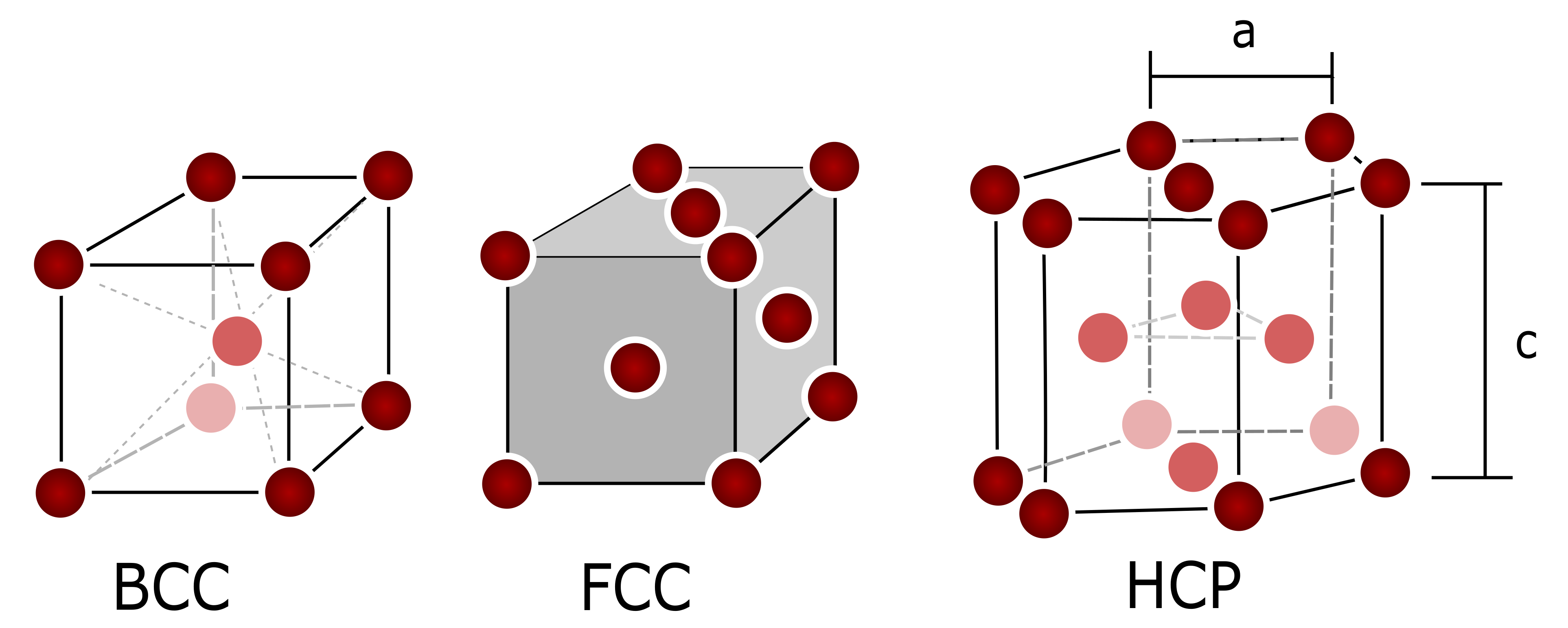
Figure 1. Three typical crystal structures in metals. BCC = Body-Centered Cubic. FCC = Face-Centered Cubic. HCP = Hexagonal Close-Packed. The form ratio for HCP is c / a , ideally c / a = 1.632 , but for example, cadmium has c / a = 1.886 and berilium has c / a = 1.586 [23].
Crystals 11 00042 g001
Figure 2. (a,b) Slip plane m g and direction s g in a FCC crystal. (c) Total dislocation in a FCC; b = 1 2 [ 1 ¯ 10 ] is the Burgers vector. (d) Partial dislocation in a FCC lattice, where the dissociation is given as b = c + d = 1 6 [ 1 ¯ 2 1 ¯ ] + 1 6 [ 2 ¯ 11 ] . Adapted from [23,24].
Crystals 11 00042 g002
Figure 3. Progressive movement of a dislocation resulting in shear plastic deformation.
Crystals 11 00042 g003
Figure 4. Ilustration of the concept of incompatibility through a moving dislocation. (Left) circuit is closed, locally compatible. (Center) plastic flow (e.g., a dislocation movement) produces an incompatible field, because the circuit is not closed by the amount b. (Right) Elastic deformations bring the field compatible.
Crystals 11 00042 g004
Figure 5. Comparison of the result obtained from two consecutive slips performed in different order.
Crystals 11 00042 g005
Figure 6. Comparison of the cup drawing between numerical simulation and experiment for CP800 material: (a) predicted thickness strain distribution and earing at punch travel 10 mm; (b) photographs of experiment specimen; (c) thickness strain distribution along the rolling direction. Reproduced from [172], under permission.
Crystals 11 00042 g006
Figure 7. Experimental and simulation results of earing profile after cup drawing for aluminium sheet: (a) comparison of results between the texture component-based crystal model and Hill 48 yield surface model and experiment; (b) simulation and experimental results in which the texture is approximated using the volume fraction; (c) simulation and experimental results in which the texture is approximated using two rolling texture components and a random texture component. Reproduced from [174], under permission.
Crystals 11 00042 g007
Figure 8. Cup drawing and springback simulation of AA6022-T4 sheet: (a) von Mises stress contours at the end of forming; (b) von Mises stress contours after springback relaxation; (c) shape change after springback of y-z profile; (d) shape change after springback of the circumference of the down cup flange. Reproduced from [178], under permission.
Crystals 11 00042 g008
Figure 9. Evolution of texture in copper under a tensile test. Upper row contains the initial and final mesh, where colors correspond to different orientation. Middle row is shows the texture pole plots evolution for direction ( 111 ) and the lower row for direction ( 100 ) . Adapted from [75], under permission. A Matlab toolbox for pole figures, and documentation, is available in https://mtex-toolbox.github.io/.
Crystals 11 00042 g009
Figure 10. Simulation results of Taylor impact test for Ta cylinder: (a) equivalent plastic strain rate contour at different time step; (b) comparison of the measured and simulated cylinder geometry after the impact with the superimposed contours of equivalent plastic strain. Reproduced from [179], under permission.
Crystals 11 00042 g010
Figure 11. Simulation results of rolling test for the uranium α -U: (a) equivalent plastic strain contours at different step; (b) comparison between measured and predicted evolution at a polycrystalline material point near the bottom surface of the plate. Reproduced from [182], under permission.
Crystals 11 00042 g011
Publisher’s Note: MDPI stays neutral with regard to jurisdictional claims in published maps and institutional affiliations.