Article

Characterization of Accumulated B-Integral of Regenerative Amplifier Based CPA Systems

1
Helmholtz-Zentrum Dresden-Rossendorf (HZDR), Bautzner Landstr. 400, 01328 Dresden, Germany
2
Technische Universität Dresden, 01062 Dresden, Germany
3
iTeox, 14 avenue Jean Jaurès, 91940 Gometz-le-chatel, France
4
Kansai Photon Science Institute (KPSI), National Institutes for Quantum and Radiological Science and Technology, 8-1-7 Umemidai, Kizugawa, Kyoto 610-0215, Japan
*
Author to whom correspondence should be addressed.
Crystals 2020, 10(9), 847; https://doi.org/10.3390/cryst10090847
Submission received: 31 August 2020 / Revised: 16 September 2020 / Accepted: 17 September 2020 / Published: 22 September 2020
(This article belongs to the Special Issue Development of High Intensity Crystal Laser and Its Applications)

Abstract

:
We report on a new approach to measure the accumulated B-integral in the regenerative and multipass amplifier stages of ultrashort-pulse high-power laser systems by B-integral-induced coupling between delayed test post-pulses and the main pulse. A numerical model for such non-linear pulse coupling is presented and compared to data taken at the high-power laser Draco with self-referenced spectral interferometry (SRSI). The dependence of the B-integral accumulated in the regenerative amplifier on its operation mode enables optimization strategies for extracted energy vs. collected B-integral. The technique presented here can, in principle, be applied to characterize any type of ultrashort pulse laser system and is essential for pre-pulse reduction.

1. Introduction

High-power laser systems are powerful instruments enabling a variety of applications in the fields of high energy density physics and relativistic laser plasma physics, with the prominent example of compact laser plasma accelerators [1,2,3]. In particular, the acceleration of protons to multi 10 MeV energies requires full control over interaction conditions and thus excellent temporal pulse contrast [4,5,6,7,8,9,10]. This key property of any high-power laser chain characterizes the temporal pulse profile relative to the peak intensity on ns to fs time scales [11]. Achievable contrast ratios are in the range of 10−12 on temporal scales between ns and few 10 ps prior to the main pulse. Contrast degrading effects are amplified spontaneous emission (ASE) in the ns range, reflections for the case of discrete pulses, scattering effects in particular in dispersive elements, incomplete pulse compression effects and others [12,13,14]. A dominating nonlinear effect is pre-pulse generation by coupling of discrete post-pulses, with the main pulse first described by Didenko et al. [15]. Post-pulses are inevitably generated when the laser pulse passes through transparent elements of the laser amplification chain, such as amplifier crystals, Pockels cells, or wave plates. As these elements are antireflection treated, typically with reflectivities of less than 0.5%, post-pulses are generated on a 10−5 level or below. They are delayed with respect to the main pulse by twice the optical path length of the element. While half wave plates, as a source of post-pulses in the range of few ps, can be avoided in amplifier chains [16], active media or Pockels cell assemblies usually cannot and the mitigation of double reflections by wedging of surfaces [17] is limited.
Amplification of stretched pulses (i.e., chirped pulse amplification, CPA) is conventionally performed in regenerative and multipass amplifiers. Multipass amplifiers are used for the amplification of pulses from mJ energy levels to joule levels and beyond. Regenerative amplifiers are applied when low energy pulses of a few microjoule or less are significantly amplified up to the mJ levels with total gain rates of 103 to 105. In closed optical cavity configurations, the seed pulse is actively injected, oscillates for a number of passes in the cavity and is then actively extracted. Linear regenerative amplifiers consist of two linear arms around a folded geometry of focusing mirrors with the active medium typically in Brewster cut in between [18]. On the linear arms thin film polarizers and Pockels cells are applied. Techniques for controlling the spectral amplification cross section can be applied using thin etalons, spatial masks in dispersive elements, birefringent filters [19] and acousto-optical programmable gain filters (Mazzler) [20]. During one round trip, the light passes each element twice, collecting the induced nonlinearities according to the material properties and the specific intensities at the element’s location. Taking into account the number of roundtrips on the order of 10 to 20 (for Ti:Sa based high gain systems), regenerative amplifiers are often the main source of material dispersion and nonlinearities accumulated in laser chains. Thus, any post-pulses generated before or in this amplification stage can dominantly cause the generation of pre-pulses.
In this paper, we derive from Didenko’s work [15] a numerical simulation of pulse coupling and generation through nonlinear temporal phase modulation and compare it with measurements of generated pre-pulses at small delays with respect to the main pulse, compared to the pulse stretching rate of the CPA system. The measurements are performed making use of the single shot self-referenced spectral field correlation technique with extended time excursion (SRSI-ETE), enabling measurements with large temporal windows (18 ps), high dynamic range (108) and pulse resolving temporal resolution (20 fs) [8,21]. This technique allowed us to measure the electric field of main, post- and generated pre-pulses in single shot. In a parallel complementary study, we demonstrated the validity of the pulse coupling concept and its dependence of the generated pre-pulse level on the square of the B-integral exploiting the same measurement technique at the J-KAREN-P laser system [22,23]. Here, we focus on measurements of the accumulated nonlinearities in a laser chain, namely, the B-integral. We show that different operation modes of the regenerative amplifier have significant impact on the collected B-integral.

2. Materials and Methods

2.1. Experimental Setup

The experimental setup employs the CPA1 stage of the Draco high-power laser, a typical combination of regenerative and multipass amplifiers equipped with an acousto-optical programmable gain filter (Mazzler, Fastlite) for spectral gain control. Self-Referenced Spectral interferometry with extended time excursion (SRSI-ETE) is applied for single-shot measurement of pulse coupling efficiency and thus accumulated B-integral (Figure 1). The Draco laser system bases on the Ti:Sa Pulsar system (Amplitude Technologies). The CPA1 stage amplifies pulses derived from a mode-locked oscillator (Femtopower Pro, Spectra Physics)/booster amplifier combination from micro joule level up to 20 mJ with 10 Hz repetition rate. The seed with ~10 µJ is sent to the Öffner-type stretcher [24] with a stretching rate of ~8.5 ps/nm leading to stretched pulses with ~0.6 ns duration. The stretched pulses pass an acousto-optical programmable dispersion filter (Dazzler, Fastlite) [25,26], used for control of spectral phase together with an automatic feedback loop, and then are seeded into a regenerative amplifier with an overall length of ~4m, resulting in a round trip time of 27.8 ns. The injection and extraction of the pulses is achieved with a single fast Pockels cell, providing two gates of 6ns full width at half maximum length and variable delay in between the gates in combination with a set of thin film polarizers. The spectral shape is enhanced to a flat top profile with >60 nm full width at half maximum (FWHM) and >70 nm at 1/e² intensity point using the Mazzler acousto-optic filter inside the cavity. After 12 round trips, the individual pulses are coupled out at gain saturation with an energy of ~1 mJ, achieved with pump energies adjustable in the range of 6–8 mJ at 532 nm. A pulse cleaning Pockels cell and polarizers, following the regenerative amplifier, enhance the nanosecond temporal contrast. For amplification up to ~20 mJ, the pulses are transferred into a 6-pass butterfly amplifier pumped by ~75 mJ pump energy at 532 nm. A fraction of the amplified pulse is sent into a double grating in-air compressor, compressing the pulses to a pulse length of ~30 fs Fourier transform limit together with a feedback loop from self-referenced spectral interferometry (SRSI / Wizzler, Fastlite) measurement to the Dazzler [27,28].
For controlled generation of post-pulses close to the main pulse a thin glass plate (BK7, thickness ~180 µm, microscope glass slide) is inserted at two different positions within the chain: in front of the regenerative amplifier and in front of the diagnostics after the compressor, for reference. The SRSI-ETE measurement setup is then placed behind the compressor to measure the pulses under the different conditions.

2.2. Numerical Model

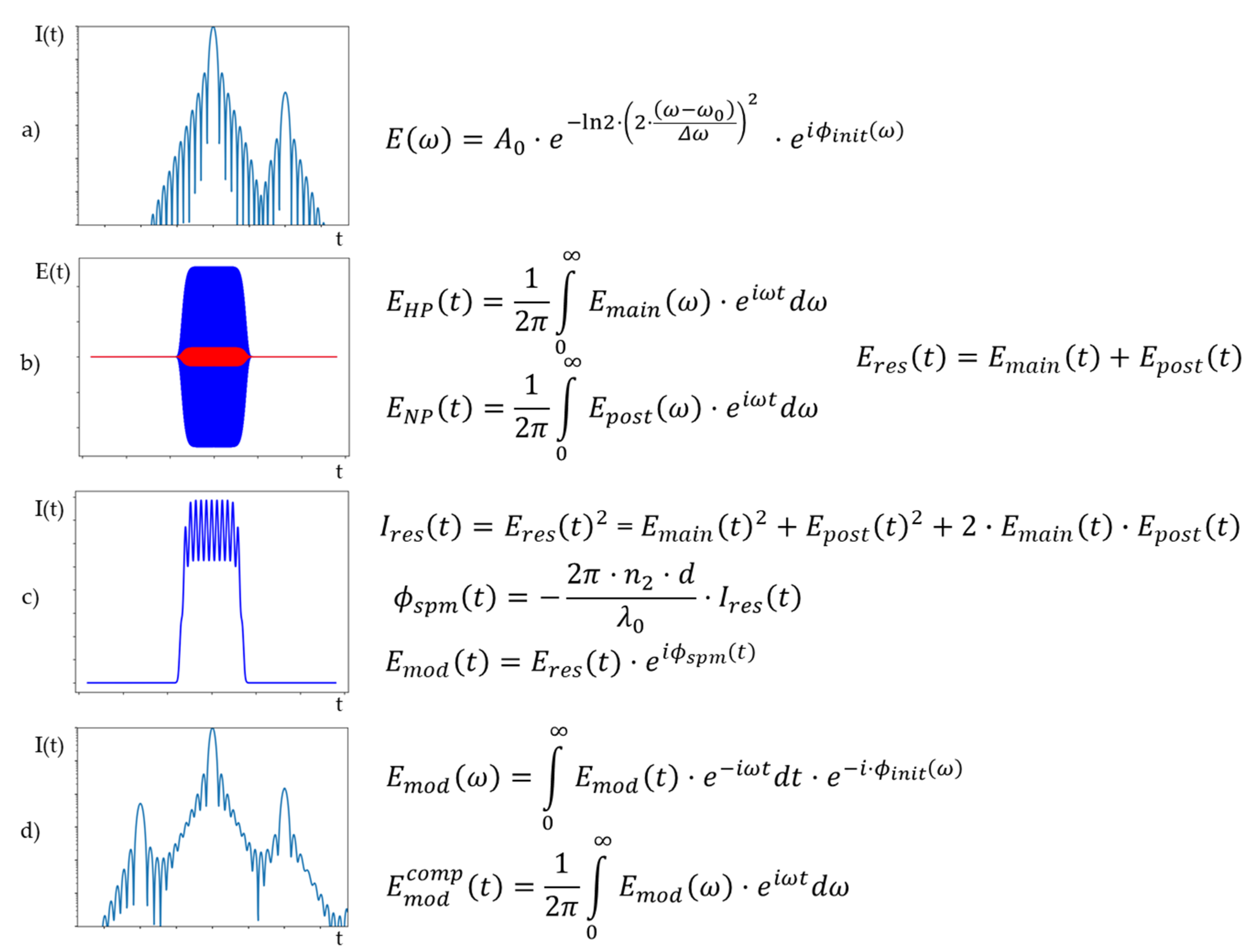
We present a model for the description of the coupling efficiency of post- to pre-pulses, following the work by Didenko et al. [15]. While his work describes the effect analytically for specific idealized pulse forms, we follow a direct numerical approach to simulate the coupling and to compare it to our measurements. Didenko et al. analyzed if the pre-pulse generation originates from amplification effects or in modulation of the temporal phase and found amplification effects to be negligible. Thus, we focus on the temporal phase modulation. The B-integral is defined as the total accumulated non-linear temporal phase shift ϕ s p m ( t ) = 2 π · n 2 λ · I ( t , z )   d z along the optical axis z , with n 2 being the non-linear refractive index, d the thickness of the material, λ the wavelength and I ( t ) the temporal intensity evolution. In our model, we assume the intensity in the relevant materials to be constant, so the accumulated temporal phase shift is simplified to ϕ s p m ( t ) = 2 π · n 2 · d λ · I ( t ) , with d being the thickness of the individual material. In Figure 2 the approach is described schematically together with the steps of the numerical modelling.
We start with a main pulse being followed by a post-pulse with delay τ. After stretching, both pulses overlap in time leading to a temporal intensity modulation due to interference of the main pulse with the post-pulse. This intensity modulation induces a temporal phase modulation via the B-integral. After compression, the newly generated pre-pulse becomes visible.
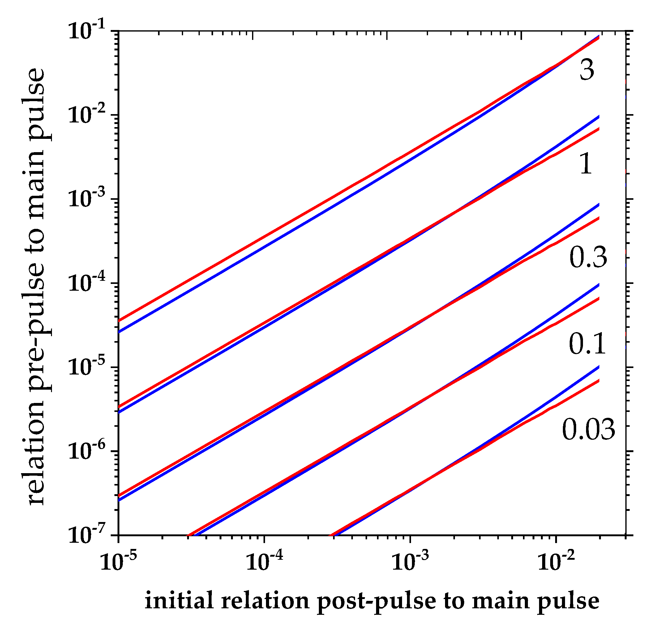
For verification of the model, we compare the expression from Didenko et al. for plane waves of the generated pre-pulse to main pulse ratio for different post-pulse to main pulse ratio:
I p r e I 0 = B 0 2 3 · I p o s t I 0
with our numerical calculations. It is noted that the analytic form depends on idealized pulse forms.
For comparison Equation (1) is used, which is valid for plane waves (spatial and temporal flat top pulses). This pulse form is not achievable in real laser systems, as well as an idealized Gaussian form. For real laser pulses, the factor between normalized pre- to post-pulses can differ for different conditions as seen in Kon et al. [22]. The advantage of applying a numerical approach is the possibility to use any temporal profile characterizing the real pulse and different temporal and spectral structures of main and post-pulse are possible to investigate. Nevertheless, to qualify the modeling it is useful to compare the analytic form to an according numerical calculation. The results are shown in Figure 3. We find a good accordance of the principle behavior and absolute values as in the work by Didenko et al.; for small values of the B-integral and small ratios of post- to main pulse, we find good agreements between numerical model and analytical equation. If any of these values rise, the modelling and analytical descriptions differ.

2.3. Amplification Modelling for B-Integral Estimation

For comparison of measured values of the accumulated B-integral in amplifier systems with expectations from material properties we use a simplified model of amplification in a laser amplifier based on the Frantz–Nodvik equation [29,30]. The model describes the amplification for one wavelength (central wavelength λ 0 =   800 nm) with a uniform beam distribution following Equation (2):
F o u t = F S · l n [ ( 1 + e F i n F S 1 ) · e n · σ e m · l ]
The initial condition of the inversion   n 0 is derived from the absorbed pump energy. The saturation fluence is given by   F S = h · c σ e m · λ 0 , with σ e m being the emission cross section at wavelength λ 0 . The calculation is performed for each pass through the active medium with spot size conditions matching the radial conditions assumed in the regenerative amplifier. According to the extracted energy, the inversion is reduced after each amplification step as an input value for the next pass. In addition, we set losses of the pulse energy after each pass of the beam to 0.5% per surface passed in the cavity.
From the calculated values for the retrieved energy per pass through the active medium, we directly evaluate the B-integral assuming a temporal pulse length of 600 ps according to stretching rate and bandwidth. We compare the critical components with respect to their individual nonlinear effect in the regen geometry following n 2 · d A derived from the definition of B-integral, with A being the area irradiated by the light at the individual positions. The results are shown in Table 1.
The comparison shows that the most critical component in the regenerative cavity is the Mazzler device with TeO2 material. One should note that different values for the n2 value can be found in literature [36,37,38]. While all values are in the range of 10−18 m²/W to 10−19 m²/W, a value of 4.48 × 10⁻¹⁹ m²/W was found to be best matching and seems to be typical for the used Mazzler material. The non-linear refractive index n2 of TeO2 of the Mazzler generates a factor of at least five higher individual nonlinearity than the other materials in the regenerative amplifier. Thus, we only considered the Mazzler to contribute for the comparison. The multipass amplifier, in contrast to the regenerative amplifier, contributes even less; the individual nonlinearity is in the range of 1.4 × 10⁻¹⁶ m/W and the number of trips through the crystal is 6, making this amplifier even less relevant for the B-integral accumulation by a factor of more than 100, taking also the number of roundtrips into account.

3. Results

3.1. B-integral Measurement under Normal Operational Conditions

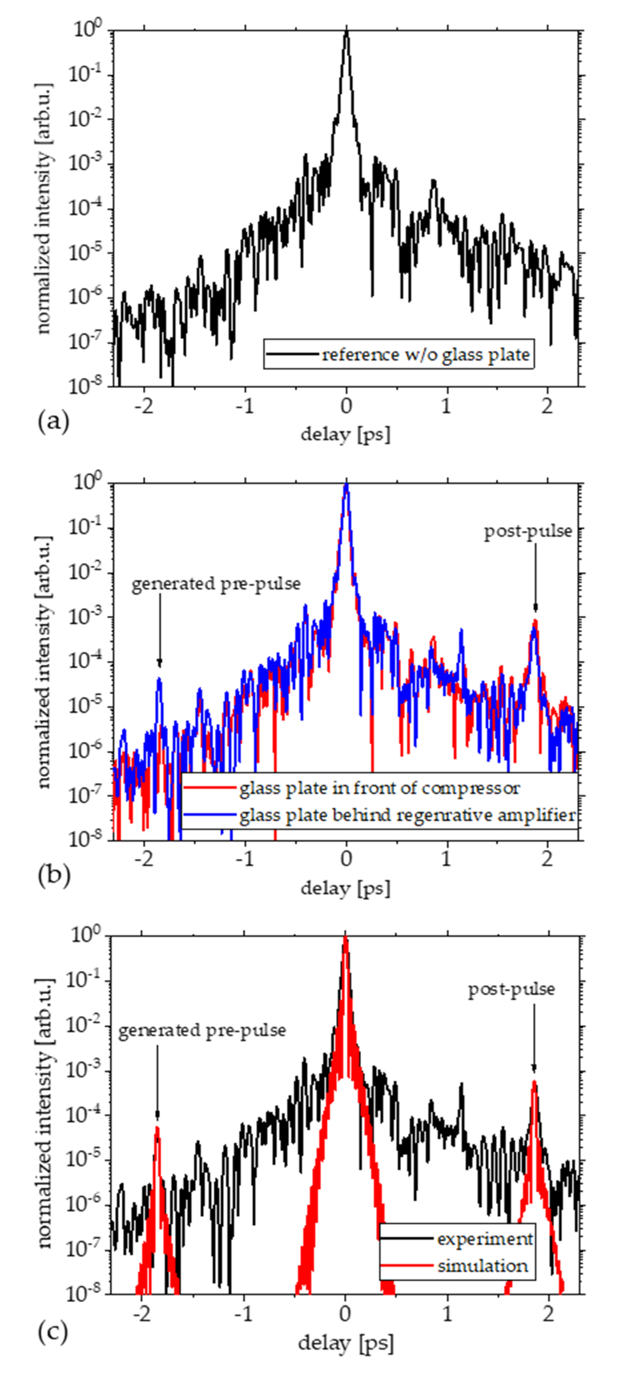
Three measurements of the temporal pulse contrast for different post-pulse conditions are presented to discuss the measurement concept under normal amplifier operation conditions. The first contrast curve depicted in Figure 4 serves as general reference and was taken without additional post-pulse generation by means of a glass plate in the beam path. Secondly, we inserted the glass plate after the compressor before the SRSI-ETE device for referencing the generated post-pulse (position 2 in Figure 1). Finally, the glass plate was placed in the beam before the regenerative amplifier in the same manner to generate not only the post-pulse, but also to induce the pulse coupling in the chain (position 1 in Figure 1).
For this measurement, we fitted the pre-pulse generation by our simulation by changing the B-integral value until the simulation found the best match with the measurement. The relative level of the post-pulse to the main pulse are 8.8 × 10⁻⁴ in case of referencing the glass plate effect in front of the SRSI-ETE device and 5.8 × 10⁻⁴ in case of placing the glass plate in front of the regenerative amplifier. Assuming a 0° reflectivity of 4.1% at 800 nm for BK7 should result in a double-reflection generated post-pulse of 16.8 × 10⁻⁴ [39]. Our measured values differ by a factor of 2 to 3, respectively. We assume that the difference originates in the optical quality of the plate (parallelism and roughness of the surfaces). Nevertheless, our method is valid, since we can compare post- and pre-pulse in a single measurement with unchanged conditions. The generated pre-pulse if the plate is placed in front of the regenerative amplifier is of 4.3 × 10⁻⁴ relative intensity to the main pulse. For best fitting with our simulation, we found an accumulated B-integral of 0.41.

3.2. Influence of Number of Roundtrips and Gain Saturation on Accumulated B-Integral

In a second measurement, we varied the pump energy of the regenerative amplifier. By increasing the pump energy, the maximum amplification (gain saturation) occurs prior to the originally chosen number of round trips until extraction. Increasing the pump energy significantly can be a way of operation to enhance the extracted pulse energy, if the extraction is done at the new maximum energy after a reduced number of roundtrips.
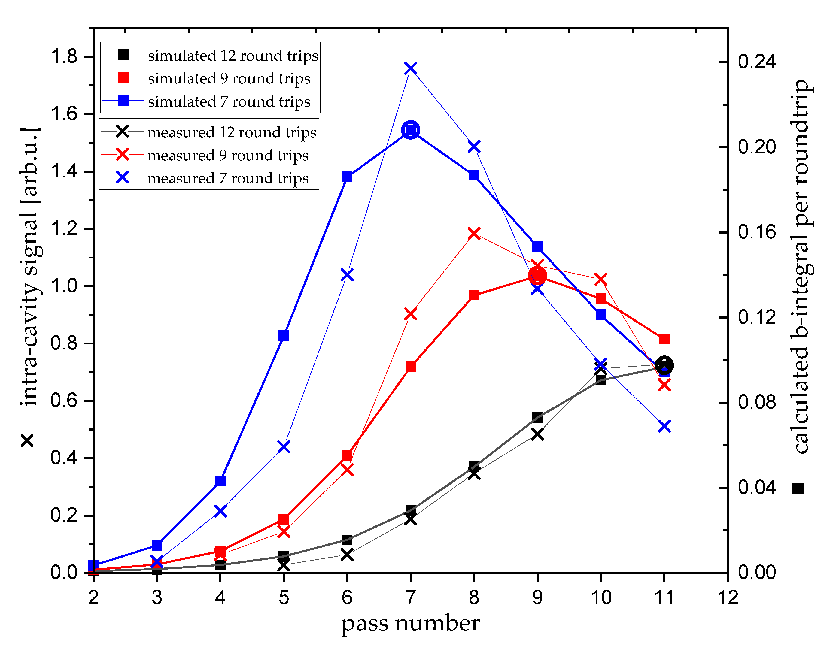
The standard number of round trips in our system is 12. We compare this normal operational mode with operation with higher pump energies for 9 and 7 round trips till maximum amplification. In our case, the extraction had to be always after 12 roundtrips to keep the dispersion management of the whole CPA system unchanged. To classify our measurements, we simulated these amplification conditions for the three different settings and compared it to the measurements of the build-up dynamics of the regenerative amplifier (Figure 5) and the accumulated B-integral. The results of relative pre-pulse level from measurement, the fitted B-integral value and the associated values for B-integral retrieved from the amplification simulation can be found in Table 2.
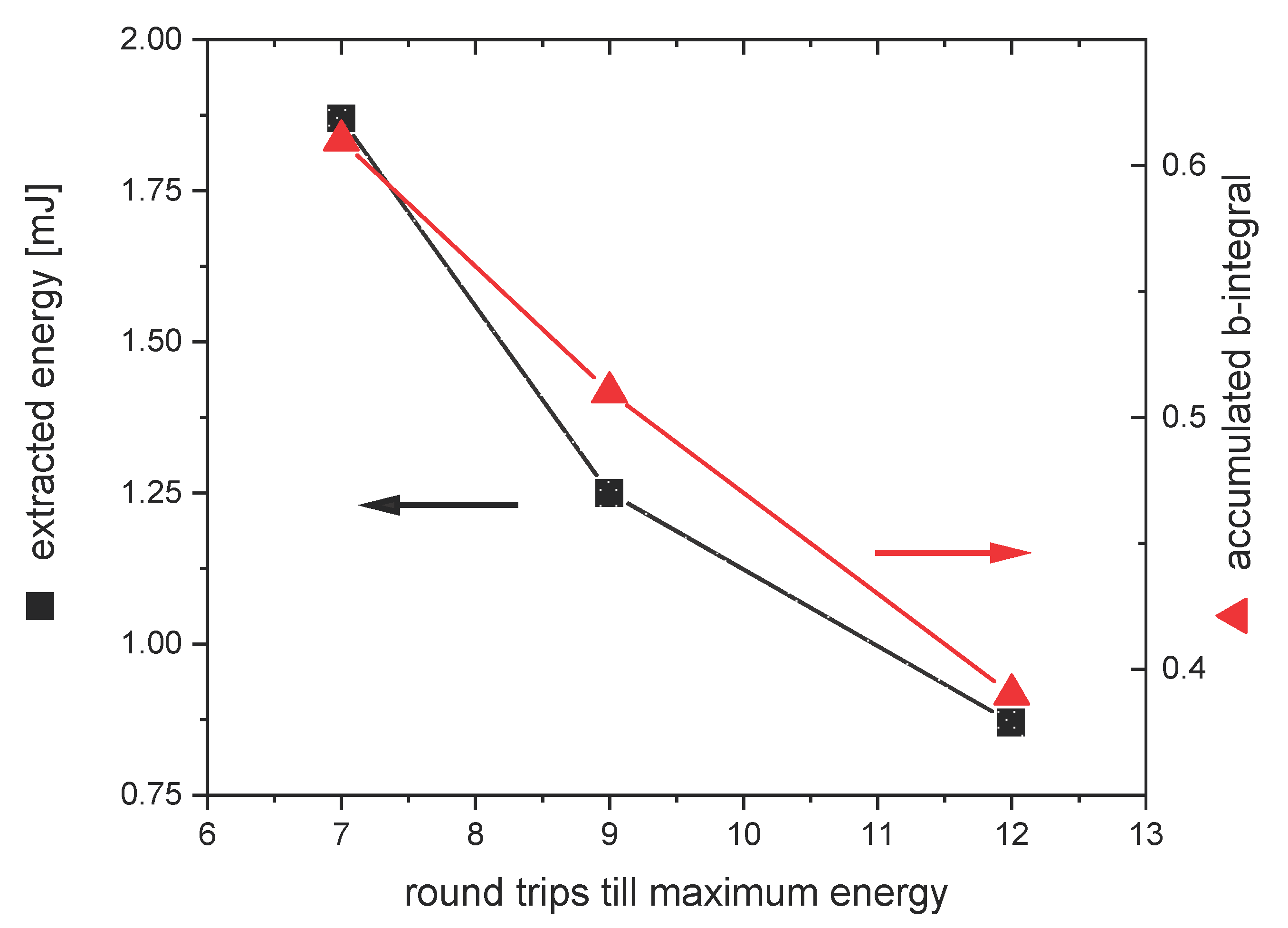
The measurements are in good agreement with our model. The analysis of this data and the calculations can also be used to derive a specific setting to balance gain and accumulated B-integral in regenerative amplifiers. Figure 6 shows the calculated extracted pulse energy, if extraction is performed at gain saturation, and the associated accumulated B-integral. The calculation shows that with higher gain and less roundtrips, the B-integral is raising, as well as the extracted pulse energy. In contrast, with less gain and more roundtrips, the B-integral is lower.

4. Discussion

We demonstrated an approach to measure the integrated B-integral of laser amplification chains. Our method combines the SRSI-ETE technique, as a single-shot field correlation measurement device, with a numerical calculation of the B-integral induced pulse coupling of post- to pre-pulses. Following this approach, we measured the integrated B-integral of a CPA laser system with a regenerative and a multipass amplifier to be 0.41 under normal operation.
We compared these retrieved values with a simple model for amplification. For the numerical calculation, we assumed that only the material of the Mazzler device dominated the B-integral. The analysis of beam sizes in the optical elements relies on geometrical beam size assumptions. These assumptions are done for the smallest beam scenario leading to maximal values in the individual nonlinearity. Under these conditions we found the individual nonlinearity of the other materials to be 20% of the Mazzler device, defining the precision of our model.
Operating the regenerative amplifier with output energy enhanced conditions, e.g., in increasing the pump energy to saturate the amplification with less roundtrips, leads to further increase of accumulated B-integral. Typically accepted maximal values for accumulated B-integral in high-power laser chains are 1 with regard to effects like self-phase modulation [40,41].
In contrast, if taking pre-pulse generation through B-integral induced pulse coupling effects into account the acceptable B-integral is reduced. Considering ionization of matter starts at 1012 W/cm² to 1013 W/cm² and state of the art high power lasers are delivering 1021 W/cm² to 1022 W/cm² in focus [4], the temporal laser pulse evolution requires a contrast level of pre-pulses of 10−9 or better. If a plasma mirror prior to the final focusing for laser matter interaction is applied, the requirements of the contrast level can be reduced to 10−7, thanks to an improvement of the contrast by at least two orders of magnitude [8]. On the other hand, post-pulses generated by reflections of unavoidable parallel anti-reflection coated surfaces (R < 0.1% per surface) can be assumed to be on the 10−6 level, compared to the main pulse in best case. Taking this into account and estimating the B-integral induces, a pulse coupling of post-pulse level 10−6 to a pre-pulse level of 10−7 leads to an acceptable B-integral of 0.55 concerning the pulse coupling effects. This restricts the capabilities of increasing the extracted energy of the regenerative amplifier. It also has to be taken into account that more B-integral will be collected in the chain during amplification.

5. Conclusions

The methods presented in this paper are capable of helping improve amplifier design and understanding. The presented technique can be applied to any part of the laser chain; investigations of the B-integral of main laser pulse amplifiers up to the tens of joule level are feasible. The numerical model opens the way to investigate the influence of higher order dispersion terms and larger delays than presented here. Further studies can also include spectral effects, as well as spatial, and their influence on the principle pulse and contrast formation of high-power laser pulses for laser driven relativistic plasma experiments.
One has to note that pulses must not only be replica generated by reflections, but also scattered light from components of the laser chain, e.g., these scattered light components can form post-pulse structures, which are then transformed through B-integral coupling to pre-pulse structures degrading the pulse contrast before the main pulse as well. In conclusion, improvements of high power lasers concerning B-integral reduction and avoidance of post-pulse generation have to be undertaken to improve the temporal contrast and circumvent applications of energy costly techniques like plasma mirrors to enhance the energy efficiency, especially if the peak power of these lasers are increasing and contrast conditions have to be maintained or even improved.

Author Contributions

Conceptualization, S.B.; Formal analysis, F.M.H., J.J.L., R.P. and T.O.; Funding acquisition, K.K. and U.S.; Investigation, S.B. and F.M.H.; Methodology, S.B., F.M.H., T.P., U.H., R.G., T.Z., A.K. and T.T.; Project administration, K.K. and U.S.; Software, J.J.L., R.P. and T.O.; Supervision, S.B., K.Z., A.I., M.N., H.K., K.K., T.T. and U.S.; Validation, R.P. and T.O.; Writing—original draft, S.B. and F.M.H.; Writing—review and editing, R.P., T.O., A.K., M.N., H.K., T.T. and U.S. All authors have read and agreed to the published version of the manuscript.

Funding

For KPSI: This research was funded by JST-Mirai Program Grant Number JPMJMI17A1, Japan, and QST President’s Strategic Grant (QST International Research Initiative (AAA98) and Creative Research (ABACS)). For HZDR / iTeox: This research received no external funding.

Acknowledgments

The authors would like to thank J.D., C.E., S.G. and P.P. for their strong support.

Conflicts of Interest

The authors declare no conflict of interest.

References

  1. Downer, M.C.; Zgadzaj, R.; Debus, A.; Schramm, U.; Kaluza, M.C. Diagnostics for plasma-based electron accelerators. Rev. Mod. Phys. 2018, 90, 035002. [Google Scholar] [CrossRef] [Green Version]
  2. Macchi, A.; Borghesi, M.; Passoni, M. Ion acceleration by superintense laser-plasma interaction. Rev. Mod. Phys. 2013, 85, 751. [Google Scholar] [CrossRef] [Green Version]
  3. Esarey, E.; Schroeder, C.B.; Leemans, W.P. Physics of laser-driven plasma-based electron accelerators. Rev. Mod. Phys. 2009, 81, 1229. [Google Scholar] [CrossRef]
  4. Schramm, U.; Bussmann, M.; Irman, A.; Siebold, M.; Zeil, K.; Albach, D.; Bernert, C.; Bock, S.; Brack, F.; Branco, J.; et al. First results with the novel Petawatt laser acceleration facility in Dresden. J. Phys. Conf. Ser. 2017, 874, 012028. [Google Scholar] [CrossRef]
  5. Kaluza, M.; Schreiber, J.; Santala, M.I.K.; Tsakiris, G.D.; Eidmann, K.; Meyer-ter-Vehn, J.; Witte, K.J. Influence of the laser prepulse on proton acceleration in thin-foil experiments. Phys. Rev. Lett. 2004, 93, 045003. [Google Scholar] [CrossRef] [PubMed]
  6. Poole, P.L.; Obst, L.; Cochran, G.E.; Metzkes, J.; Schlenvoigt, H.-P.; Prencipe, I.; Kluge, T.; Cowan, T.E.; Schramm, U.; Schumacher, D.W.; et al. Laser-driven ion acceleration via target normal sheath accelerationin the relativistic transparency regime. New J. Phys. 2018, 20, 013019. [Google Scholar] [CrossRef]
  7. Obst, L.; Göde, S.; Rehwald, M.; Brack, F.E.; Branco, J.; Bock, S.; Bussmann, M.; Cowan, T.E.; Curry, C.B.; Fiuza, F.; et al. Efficient laser-driven proton acceleration from cylindrical and planar cryogenic hydrogen jets. Sci. Rep. 2017, 7, 10248. [Google Scholar] [CrossRef]
  8. Obst, L.; Metzkes-Ng, J.; Bock, S.; Cochran, G.E.; Cowan, T.E.; Oksenhendler, T.; Poole, P.L.; Prencipe, I.; Rehwald, M.; Rödel, C.; et al. On-shot characterization of single plasma mirror temporal contrast improvement. Plasma Phys. Control. Fusion 2018, 60, 054007. [Google Scholar] [CrossRef] [Green Version]
  9. Cerchez, M.; Prasad, R.; Aurand, B.; Giesecke, A.L.; Spickermann, S.; Brauckmann, S.; Aktan, E.; Swantusch, M.; Toncian, M.; Toncian, T.; et al. ARCTURUS laser: A versatile high-contrast, high-power multi-beam laser system. High Power Laser Sci. Eng. 2019, 7, e37. [Google Scholar] [CrossRef] [Green Version]
  10. Ziegler, T.; Bernert, C.; Bock, S.; Brack, F.-E.; Cowan, T.E.; Dover, N.P.; Garten, M.; Gaus, L.; Gebhardt, R.; Helbig, U.; et al. PW-class laser-driven proton acceleration optimization by application of temporally asymmetric pulse shapes. arXiv 2020, arXiv:2007.11499v1. [Google Scholar]
  11. Kiriyama, H.; Pirozhkov, A.S.; Nishiuchi, M.; Fukuda, Y.; Ogura, K.; Sagisaka, A.; Miyasaka, Y.; Mori, M.; Sakaki, H.; Dover, N.P.; et al. High-contrast high-intensity repetitivepetawatt laser. Opt. Lett. 2018, 43, 2595–2598. [Google Scholar] [CrossRef] [PubMed]
  12. Khodakovsky, N.; Kalashnikov, M.; Gontier, E.; Falcoz, F.; Paul, P.-M. Degradation of picosecond temporal contrast of Ti:sapphire lasers with coherent pedestals. Opt. Lett. 2016, 41, 4441–4444. [Google Scholar] [CrossRef] [PubMed]
  13. Kalashnikov, M.; Osvay, K.; Sandner, W. High-power Ti:Sapphire lasers: Temporal contrast and spectral narrowing. Laser Part. Beams 2007, 219–223. [Google Scholar] [CrossRef]
  14. Nantel, M.; Itatani, J.; Tien, A.-C.; Faure, J.; Kaplan, D.; Bouvier, M.; Buma, T.; Van Rompay, P.; Nees, J.; Pronko, P.P.; et al. Temporal contrast in Ti:sapphire lasers: Characterization and control. IEEE J. Sel. Top. Quantum Electron. 1998, 4, 449–458. [Google Scholar] [CrossRef]
  15. Didenko, N.V.; Konyashchenko, A.V.; Lutsenko, A.P.; Tenyakov, S.Y. Contrast degradation in a chirped-pulse amplifier due to generation of prepulses by postpulses. Opt. Express 2008, 16, 3178–3190. [Google Scholar] [CrossRef] [PubMed]
  16. Keppler, S.; Honrung, M.; Bödefeld, R.; Kahle, M.; Hein, J.; Kaluza, M.C. All-reflective, highly accurate polarization rotator for high-power short-pulse laser systems. Opt. Express 2012, 20, 20742–20747. [Google Scholar] [CrossRef]
  17. Kiriyama, H.; Miyasaka, Y.; Sagisaka, A.; Ogura, K.; Nishiuchi, M.; Pirozhkov, A.S.; Fukuda, Y.; Kando, M.; Kondo, K. Experimental investigation on the temporal contrast of pre-pulses by post-pulses in a petawatt laser facility. Opt. Lett. 2020, 45, 1100–1103. [Google Scholar] [CrossRef]
  18. Kogelnik, H.; Ippen, E.P.; Dienes, A.; Shank, C.V. Astigmatically compensated cavities for CW dye lasers. IEEE J. Quantum Electron. 1972, 8, 373–379. [Google Scholar] [CrossRef]
  19. Barty, C.P.J.; Korn, G.; Raksi, F.; Rose-Petruck, C.; Squier, J.; Tien, A.-C.; Wilson, K.R.; Yakovlev, V.V.; Yamakawa, K. Regenerative pulse shaping and amplification of ultrabroadband optical pulses. Opt. Lett. 1996, 21, 219–221. [Google Scholar] [CrossRef] [PubMed]
  20. Oksenhendler, T.; Kaplan, D.; Tournois, P.; Greetham, G.M. Intracavity acousto-optic programmable gain control for ultra-wide-band regenerative amplifiers. Appl. Phys. B 2006, 83, 491. [Google Scholar] [CrossRef]
  21. Oksenhendler, T.; Bizouard, P.; Albert, O.; Bock, S.; Schramm, U. High dynamic, high resolution and wide range single shot temporal pulse contrast measurement. Opt. Express 2017, 25, 12588–12600. [Google Scholar] [CrossRef] [PubMed]
  22. Kon, A.; Nishiuchi, M.; Kiriyama, H.; Kando, M.; Bock, S.; Ziegler, T.; Pueschel, T.; Zeil, K.; Schramm, U.; Kondo, K. Single-shot measurement of post-pulse-generated pre-pulse in high-power laser systems. Crystals 2020, 10, 657. [Google Scholar] [CrossRef]
  23. Kiriyama, H.; Pirozhkov, A.S.; Nishiuchi, M.; Fukuda, Y.; Ogura, K.; Sagisaka, A.; Miyasaka, Y.; Sakaki, H.; Dover, N.P.; Kondo, K.; et al. Status and progress of the J-KAREN-P high intensity laser system at QST. High Energy Density Phys. 2020, 36, 100771. [Google Scholar] [CrossRef]
  24. Cheriaux, G.; Rousseau, P.; Salin, F.; Chambaret, J.P.; Walker, B.; Dimauro, L.F. Aberration-free stretcher design for ultrashort-pulse amplification. Opt. Lett. 1996, 21, 414–416. [Google Scholar] [CrossRef] [PubMed]
  25. Tournois, P. Acousto-optic programmable dispersive filter for adaptive compensation of group delay time dispersion in laser systems. Opt. Commun. 1997, 140, 245–249. [Google Scholar] [CrossRef]
  26. Kaplan, D.; Tournois, P. Theory and performance of the acousto optic programmable dispersive filter used for femtosecond laser pulse shaping. Phys. IV Fr. 2002, 12, 69–75. [Google Scholar] [CrossRef]
  27. Oksenhendler, T.; Coudreau, S.; Forget, N.; Crozatier, V.; Grabielle, S.; Herzog, R.; Gobert, O.; Kaplan, D. Self-referneced spectral interferometry. Appl. Phys. B 2010, 99, 7–12. [Google Scholar] [CrossRef]
  28. Moulet, A.; Grabielle, S.; Cornaggia, C.; Forget, N.; Oksenhendler, T. Single-shot, high-dynamic-range measurement of sub-15 fs pulses by self-referenced spectral interferometry. Opt. Lett. 2010, 35, 3856–3858. [Google Scholar] [CrossRef]
  29. Frantz, L.M.; Nodvik, J.S. Theory of pulse propagation in a laser amplifier. J. Appl. Phys. 1963, 34, 2346–2349. [Google Scholar] [CrossRef]
  30. Jeong, J.; Cho, S.; Yu, T.J. Numerical extension of Frantz-Nodvik equation for double-pass amplifiers with pulse overlap. Opt. Express 2017, 25, 3946–3953. [Google Scholar] [CrossRef]
  31. Rivera, V.A.G.; Manzani, D. Technological advances in tellurite glasses. In Springer Series in Material Science, 1st ed.; Springer: Berlin/Heidelberg, Germany, 2017. [Google Scholar]
  32. Forget, N.; (Fastlite, Antibes, France). Personal communication, 2020.
  33. Major, A.; Yoshino, F.; Nikolakakos, I.; Aitchison, J.S.; Smith, P.W.E. Dispersion of the nonlinear refractive index in sapphire. Opt. Lett. 2004, 29, 602–604. [Google Scholar] [CrossRef] [PubMed]
  34. Wang, D.; Li, T.; Wang, S.; Wang, J.; Wang, Z.; Xu, X.; Zhang, F. Study on nonlinear refractive properties of KDP and DKDP crystals. RSC Adv. 2016, 6, 14490–14495. [Google Scholar] [CrossRef]
  35. Wang, D.; Li, T.; Wang, S.; Wang, J.; Shen, C.; Ding, J.; Li, W.; Huang, P.; Lu, C. Characteristics of nonlinear optical absorption and refraction for KDP and DKDP crystals. Opt. Mater. Express 2017, 7, 533–541. [Google Scholar] [CrossRef]
  36. Al-Salami, A.E. Thermal stability, linear and nonlinear refractive indices of heavy ternary tellurite glass. J. Ovonic Res. 2016, 12, 309–316. [Google Scholar]
  37. Kim, S.H.; Yoko, T.; Sakka, S. Linear and nonlinear optical properties of TeO2 glass. J. Am. Ceram. Soc. 1993, 76, 2486–2490. [Google Scholar] [CrossRef]
  38. Kim, S.H.; Yoko, T. Nonlinear optical properties of TeO2-based glasses: MOx-TeO2 (M = Sc, Ti, V, Nb, Mo, Ta, and W) binary glasses. J. Am. Ceram. Soc. 1995, 78, 1061–1065. [Google Scholar] [CrossRef]
  39. RefractiveIndex.info. Available online: https://refractiveindex.info (accessed on 7 July 2020).
  40. Konoplev, O.A.; Meyerhofer, D.D. Cancellation of B-integral accumulation for CPA lasers. IEEE J. Sel. Top. Quantum Electron. 1998, 4, 459–469. [Google Scholar] [CrossRef]
  41. Sung, J.H.; Yu, T.J.; Lee, S.K.; Jeong, T.M.; Choi, I.W.; Ko, D.-K.; Lee, J. Design of a femtosecond Ti:sapphire laser for generation and temporal optimization of 0.5-PW laser pulses at a 0.1-Hz repetition rate. J. Opt. Soc. Korea 2009, 13, 53–59. [Google Scholar] [CrossRef]
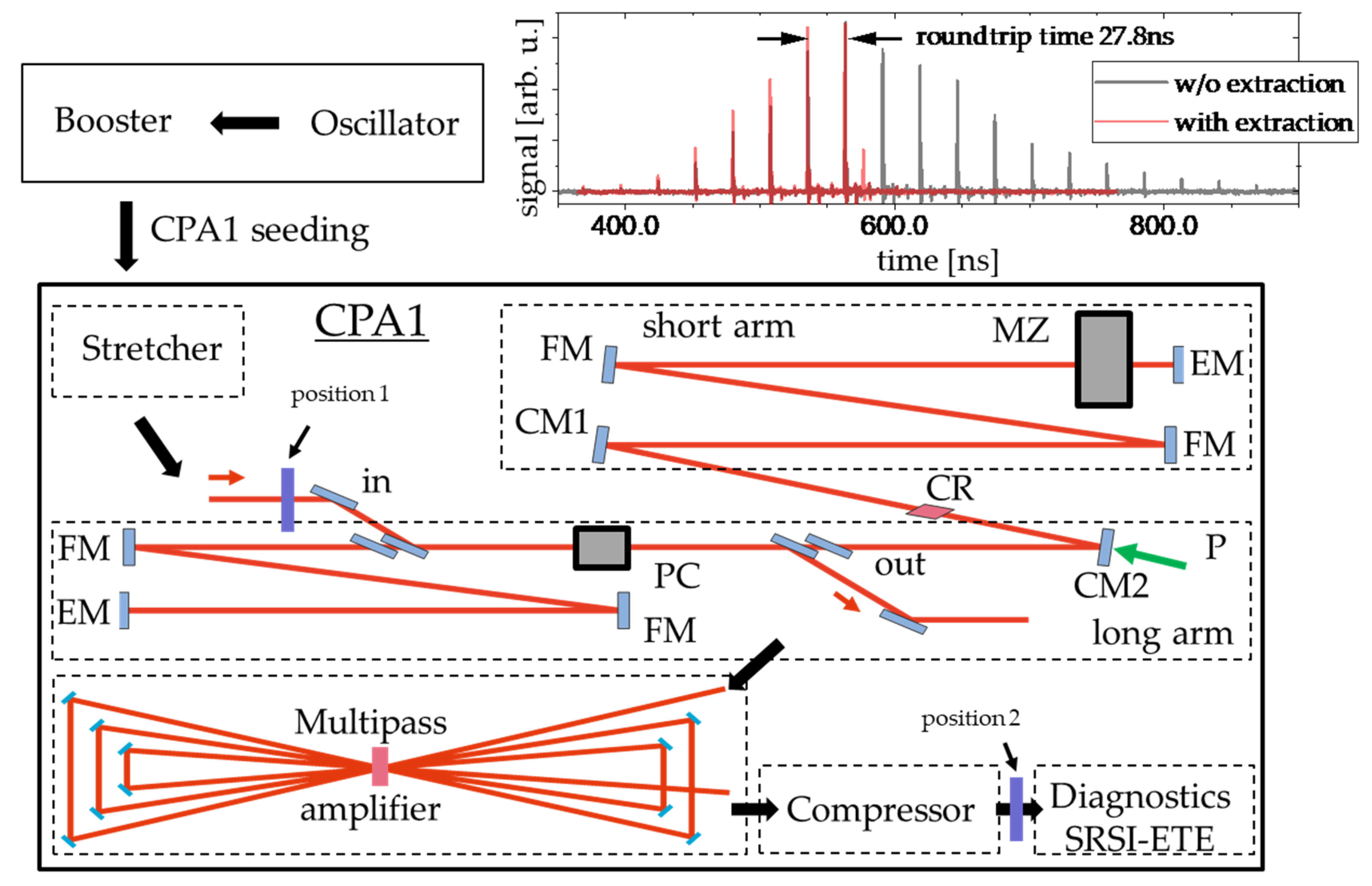
Figure 1. Experimental setup around the CPA1 stage of the Draco high-power laser system. An oscillator is followed by a pre-amplifier stage called booster. After that pulses with 10 Hz repetition rate are sent into a Öffner-type stretcher and a Dazzler. The stretched pulses are then seeded into the regenerative amplifier having a folded (FM folding mirror) geometry and a round trip time between the end mirrors (EM) of 27.8 ns (upper inset: measurement of roundtrip energy with a photodiode behind EM). The injection and extraction is performed with a double switching Pockels cell (PC) and a set of thin film polarizers in the long arm. The active material (CR) is placed between the curved mirrors (CM1 & CM2). The pump light at 532 nm is focused onto the crystal through CM2. For controlling the spectral bandwidth, a Mazzler device (MZ) is applied in the short arm. The regenerative amplifier is followed by a 6-pass amplifier and subsequent a grating compressor, delivering pulses of 30 fs FWHM temporal pulse length and 10−20 mJ energy. Behind the compressor the SRSI-ETE device is applied for single-shot measurements using a fraction of the compressed laser pulses. The glass plate generating post-pulses can be placed at position 2 before the SRSI-ETE device as reference and at position 1 for measuring the coupling in the laser chain.
Crystals 10 00847 g001
Figure 2. Description of the numerical simulation routine: (a) a main pulse and a post-pulse are generated in spectral domain together with their phase ( ϕ i n i t spectral phase including delay, ω 0 central frequency, Δ ω   FWHM bandwidth, A 0 envelope). For checking of the initial intensity conditions both pulses are Fourier transformed with just the delay into time domain; (b) both pulses (blue: main pulse, red: post-pulse) are Fourier transformed to the temporal domain (stretched) and forming a joint electric field; (c) the joint electric field leads due to interference to a temporal intensity distribution with a modulated term. This term leads to a modulated nonlinear temporal phase retroacting back onto the joint field; (d) compression leads to a newly generated pre-pulse in the temporal domain.
Crystals 10 00847 g002
Figure 3. Validation of numerical simulation. We calculated with our model for different B-integral values (label on right side) and relative post-pulse magnitudes the resulting relative pre-pulse strength (red). For comparison, the same values were analytically calculated using Equation (1) (blue).
Crystals 10 00847 g003
Figure 4. Measurement of non-linear pulse coupling with SRSI-ETE. The shown contrast traces are derived from the squared AC line of the Fourier transformed interferogram; (a) shows the reference measurement without any glass plate. (b) shows the measurement if the glass plate is inserted behind compression (position 2 in Figure 1) and the measurement with pulse coupling if the glass plate is applied in front of the regenerative amplifier (position 1 in Figure 1). (c) shows the measured trace for pulse coupling together with the matched calculation leading to a B-integral value of 0.41.
Crystals 10 00847 g004
Figure 5. Measurement vs. calculation of the build-up in a regenerative amplifier and the B-integral per roundtrip. The crosses are showing the intracavity signal during build-up, measured by a photodiode placed behind one of the regenerative amplifier end mirrors. In comparison to that, the rectangles show the B-integral per pass during amplification for each setting respectively. The theoretical point of gain saturation, optimal for extraction, is marked by circles respectively.
Crystals 10 00847 g005
Figure 6. Calculation of extracted energy (black squares) and accumulated B-integral (red triangles) vs. the number of roundtrips until extraction at gain saturation. More roundtrips (less pump energy) leads to lower accumulated B-integral and lower extracted energies.
Crystals 10 00847 g006
Table 1. Comparison of individual nonlinearities.
Materialn2 [m²/W]Individual Nonlinearity [m/W]
TeO2 [31,32]4.48 × 10−194.4 × 10⁻¹⁵
Sapphire [33]3 × 10−209 × 10−16
DKDP [34,35]1 × 10−195 × 10−16
Table 2. Roundtrips till gain saturation vs. accumulated B-integral for fixed outcoupling after 12 roundtrips.
Roundtrips Till Gain SaturationRelative Value of Generated Pre-PulseB-Integral from FitB-Integral Derived from Amplification Simulation
124.3 × 10−50.410.39
98.9 × 10−50.690.73
72.65 × 10−40.971.1