Review

Angle-Resolved Photoemission Study on the Band Structure of Organic Single Crystals

Department of Physics and Astronomy, University of Rochester, Rochester, NY 14627, USA
*
Author to whom correspondence should be addressed.
Crystals 2020, 10(9), 773; https://doi.org/10.3390/cryst10090773
Submission received: 7 August 2020 / Revised: 27 August 2020 / Accepted: 28 August 2020 / Published: 1 September 2020
(This article belongs to the Special Issue Charge Transfer Crystals)

Abstract

:
Angle-resolved photoemission spectroscopy (ARPES) is a vital technique, collecting data from both the energy and momentum of photoemitted electrons, and is indispensable for investigating the electronic band structure of solids. This article provides a review on ARPES studies of the electronic band structure of organic single crystals, including organic charge transfer conductors; organic semiconductors; and organo-metallic perovskites. In organic conductors and semiconductors, band dispersions are observed that are highly anisotropic. The Van der Waals crystal nature, the weak electron wavefunction overlap, as well as the strong electron-phonon coupling result in many organic crystals having indiscernible dispersion. In comparison, organo-metallic perovskite halides are characterized by strong s-p orbitals from the metal and halide at the top of the valence bands, with dispersions similar to those in inorganic materials.

Graphical Abstract

1. Introduction

Electronic band structure is essential to explain many physical properties of solids, and serves as the foundation for understanding all solid-state devices. The formation of electronic bands is mainly from the overlapping of the wavefunctions of the outermost electrons (valence electrons) of the atoms and molecules. The total width of the occupied portion of the bands below the Fermi level is typically in the order of 10 eV. The more tightly bound inner shell electrons have very narrow bands, because they do not overlap to a large extent. The electronic band structure is itself a property of the crystal, and as a result possesses the symmetry of the crystal [1].
A fundamental question of organic crystals is how the electronic properties of the material will be determined by the molecular structure and the packing, which will have an effect on the transport characteristics in devices [2,3,4,5,6,7,8]. The current understanding of this structure-property relationship is restricted by a few factors. While the electronic structures of the organic molecules are usually very sensitive to impurities and the morphology of the material, the properties derived from the device measurements can be influenced by the fabrication procedure and device structure. It is hence vital to explore the electronic structure directly on a pristine surface of a highly ordered system, such as ordered thin films, or more ideally, single crystals. Therefore, the uncertainties caused by external sources can be eliminated, and the intrinsic properties of the material can be understood comprehensively. Organic single crystals are perfect systems with high material purity and crystallinity, both of which are essential for electronic band structure studies that are of both fundamental and practical interest. As the prototypical systems with the highest degree of order, organic single crystals can provide valuable information on the contribution of the coherent band-like transport behavior in the charge transport mechanism. They are also suitable test beds to examine the upper limit of the carrier mobility in the organic thin film devices for various applications.
One of the most suitable and widely used techniques to study the electronic structure of a material is photoemission spectroscopy (PES) [9]. Based on the photoelectric effect as explained by Einstein in 1905 [10], photoelectrons are created via the interaction between the irradiating photons and the sample. Shown in Figure 1a is the schematic of PES. The electrons are excited by the incident photons on the sample, and if the excited electrons have sufficient energy to escape to the vacuum, they can then be detected by an electron energy analyzer.
In a simple model which does not show any energy loss during the photoemission process, the total energy must be conserved. It suggests that the kinetic energy of the emitted electrons equals the incident photon energy minus the initial binding energy (BE) of the corresponding bound electronic states. The relation can be expressed as follows [11]:
E K = h v E B Φ
where E K is the kinetic energy of the photoemitted electron, h v is the photon energy, E B is the BE of the initial state of the electron with respect to the Fermi level, and Φ is the work function of the material.
Photons with a known energy are applied to excite electrons out of the sample surface in a PES experiment. The kinetic energy and the momentum of the excited electrons can be measured by an electrostatic analyzer placed close to the surface. As indicated in Figure 1b, in the schematic representation of PES, the photoelectrons are from the occupied energy levels, including the valence bands (VB) and the core-level states which correspond to the closed atomic shells. Moreover, shown schematically in Figure 1b are secondary electrons excited by the photoelectrons that define the vacuum level cutoff [12].
Another significant aspect of PES is its surface sensitivity. For this surface analytic tool, the photoexcited electrons are used as the probing particles which have a strong interaction with the solid, leading to a relatively short escape distance, known as the mean free path (MFP). The MFP is the average distance that the particles can travel between inelastic collisions. It strongly depends on the kinetic energy of the photoelectron and is relatively independent of the materials [13]. The thickness of a monolayer is material dependent, typically ranging from 0.2–0.4 nm. It is noticed that, within the energy range of interest, which is between 10 to 2000 eV, the MFP is in the order of only 1–10 monolayers, depending on the kinetic energy of the photoelectrons.
In a photoemission process, not only the energy but also the momentum can be observed. The energy band dispersion E( k ) of a crystalline sample can be obtained if the momentum of the photoelectrons is also measured in addition to the kinetic energy with an angle-resolved electron energy analyzer. This technique is named as angle-resolved photoemission spectroscopy (ARPES) [14,15].
Figure 1c is the photoemission geometry and the relation of the electron wave vectors in vacuum ( K ) and in solid ( k ). The final states in the solid can be assumed as the free-electron-like dispersion, and the energy of the excited electrons before escaping the surface is:
E k = 2 k 2 2 m * + V 0
where m * is the effective mass of the photoexcited electron in the final state, k is the electron wave vector in solid, V 0 is the potential step to overcome by the photoexcited electron to leave the surface. When the electrons escape the surface into the vacuum, the measured kinetic energy E k is described by the following expression:
E k = 2 K 2 2 m 0 = 2 ( K 2 + K 2 ) 2 m 0
where m 0 is the free electron mass, K and K are the surface normal and parallel components of the wave vector K in vacuum, respectively. If the emission angle with respect to the surface normal is θ , then the two components are:
K = K   s i n θ ;   K = K   c o s θ
Note in Figure 1c that the parallel momentum component is conserved ( k = K ), while the perpendicular momentum component is not ( k K ). Thus, the surface parallel and normal components of the momentum of the photoexcited electron in the solid can be expressed as:
k = 2 m E k sin θ
k = 2 m ( E k cos 2 θ V 0 )
where m can be taken as m 0 if the final state is of high enough energy. The band dispersions along with the k or the k direction of the sample can be measured by varying the emission angle θ or the incident photon energy to tune the electron kinetic energy E k . The choice of the steps ( Δ θ ) is critical, since the size of the Brillouin Zone (BZ) of organic single crystals is relatively small.
To obtain the perpendicular component k , one needs to know the value of the potential step V0. Initially treated as a fitting parameter [16], experimental techniques have been developed to determine its value experimentally, by looking at the emission intensity at the band center and edges where the density of states is high [8]. To simplify the matter, it is often done with the initial state from a flat band; thus, there will be a spectral maxima corresponding to the critical points of the upper final states that is nearly free-electron like and parabolic. V0 can then be obtained using Equation (1) while the effective mass is taken to be that of the free electron one, as the photon energy is usually high enough to excite the photoelectrons to a high lying final state where the nearly free-electron parabolic dispersion is a good approximation. It is typically done by measuring the ARPES normal to the surface as a function of the photon energy. Another way is by injecting low energy electrons perpendicularly to the surface, and measuring the transmitted electron current as a function of the incident electron energy (low-energy-electron transmission (LEET)) [8].
Typical photon sources for ARPES are He lamp and synchrotron light source [9]. A He lamp is a laboratory based light source emitting photons at fixed energies (He I at hν = 21.2 eV, and He II at hν = 40.8 eV). When a He lamp is used as the light source in photoemission spectroscopy, the technique is often referred to as ultraviolet photoemission spectroscopy (UPS), and when combined with angular resolution, the technique is then called angle-resolved UPS or ARUPS. However, in this article, we use ARPES instead, as it is more widely observed in the literature. The fixed photon energy of He lamp source does not allow for free selection of the final state, and only k can be precisely determined. A synchrotron light source is much more versatile with adjustable monochromatic photon energies, and is indispensable to reach the whole BZ or to determine the value of V0. The advantage of the He lamp is that it can readily be used in a laboratory environment, as opposed to a synchrotron light source that is typically only found at an expensive facility shared by many users and involves significantly more resources.
The electron energy analyzer is typically based on deflection by a transverse electrostatic field [9]. An advanced one is equipped with a position sensitive electron detector that allows the simultaneous collection of data within an energy window and an angular distribution perpendicular to the direction of the energy dispersion. Another more recent development is angle resolved time of flight (ARTOF) electron energy analyzer, whose energy resolution is deduced from the flying time of the emitted photoelectrons. The technique requires a pulsed photon source due to the basic principle of ARTOF, namely measurement of the flying time of an electron from a sample to the detector, and allows simultaneous collection of a 3-dimensional set of data containing the whole range of the kinetic energies of the photoelectrons, as well as the k||-band structure using a position sensitive electron detector [9].
The studies on the electronic structure of organic charge transfer materials date back to the 1960s [17]. In the past few decades, research and development on organic materials and devices have grown rapidly. Compared to their inorganic counterparts, organic materials have advantages, including a wide range of the electronic and mechanical properties, such as flexibility, solubility, and tunable energy band gaps through chemical synthesis. It is thus possible to tailor the molecules in order to satisfy the specific requirements. Another attractive feature for organic molecules rises from the nature of molecular bonding. In contrast to the hard and relatively robust inorganic semiconductors that are covalently bonded, in organic solids, the interaction between the molecules is typically van der Waals [18]. Therefore, organic molecules are typically soft and fragile, which grants them the ability to be applied over large areas and to a wide variety of substrates, including mechanically flexible ones. Some mechanical properties have received lots of attention in recent years, as the researchers seek wider applications of the organic crystals. For example, the bending of organic crystals is important because they have major implications for the processing and handling of materials in industry [19]. Understanding the relationship among mechanical properties, crystal structure and tableting behavior helps to show the essence of structure based assessment of mechanical properties of organic crystals. Arkhipov et al. observed the plasticity of L-Leucinium hydrogen maleate crystals preserved at cryogenic temperatures [20]. The modifications and predictions of solubility of the organic crystals were reported by Zhang et al. and Nicoud et al. respectively [21,22]. Furthermore, the simple processing nature of organic materials provides great potential for low-cost mass production. For example, most of the small organic molecules can be evaporated at relatively low temperatures [23].
A substantial amount of ARPES measurements have been carried out on highly ordered organic monolayers or a few layers grown on non-reactive substrates [8,24,25,26,27,28,29,30,31,32,33,34,35,36,37,38,39,40,41,42,43]. There has been a comprehensive review on these ARPES measurements [8]. Band dispersion has been observed, that provides important insights on the charge transfer properties of organic crystals, and is especially valuable for understanding devices typically fabricated in the form of thin films. However, it also became apparent, that as the ordered structure can only be gained for a monolayer or a few layers, the influence from the interface interaction may not be completely excluded. Furthermore, the structure of the organic layers may differ from the bulk and may even be layer dependent [2]. Besides the experimental techniques like APRES, computational analyses also play an important role in the study of organic crystals. Significant work using computational techniques on organic materials has generated important insights on the band structures and electronic properties of these materials [44,45,46,47,48,49,50,51,52,53]. To avoid these complications, ARPES measurements on a well-prepared single crystal surface are necessary. This article aims to review ARPES studies of the electronic band structure of organic single crystals, many of which are charge transfer ones. As ARPES work on the electronic structures of crystalline organic thin films have been comprehensively reviewd by Ueno et al. [8,43], it will not be covered in this article. Another important ARPES application for imaging organic molecular orbitals instead of mapping the electronic band will also not be included here [54].

2. Organic Charge Transfer Conductors

One of the organic charge transfer crystals first studied with ARPES is a bis(ethylenedithio)-tetrathiafulvalene (BEDT-TTF) derivative, α-(BEDT-TTF)2I3 [55]. It undergoes a metal-to-insulator transition at 135 K [56], but the β phase has a superconducting ground state, Tc = 1.5 K [57]. These facts make (BEDT-TTF)2I3 suitable for studies of the relationship between the crystal structure and electronic properties. The crystal is triclinic with the unit cell described by a = 9.211 Å, b = 10.850 Å, c = 17.488 Å, α = 96.95°, β = 97.97°, and γ = 90.75° [58]. The ARPES investigation was on in situ cleaved single crystals [55].
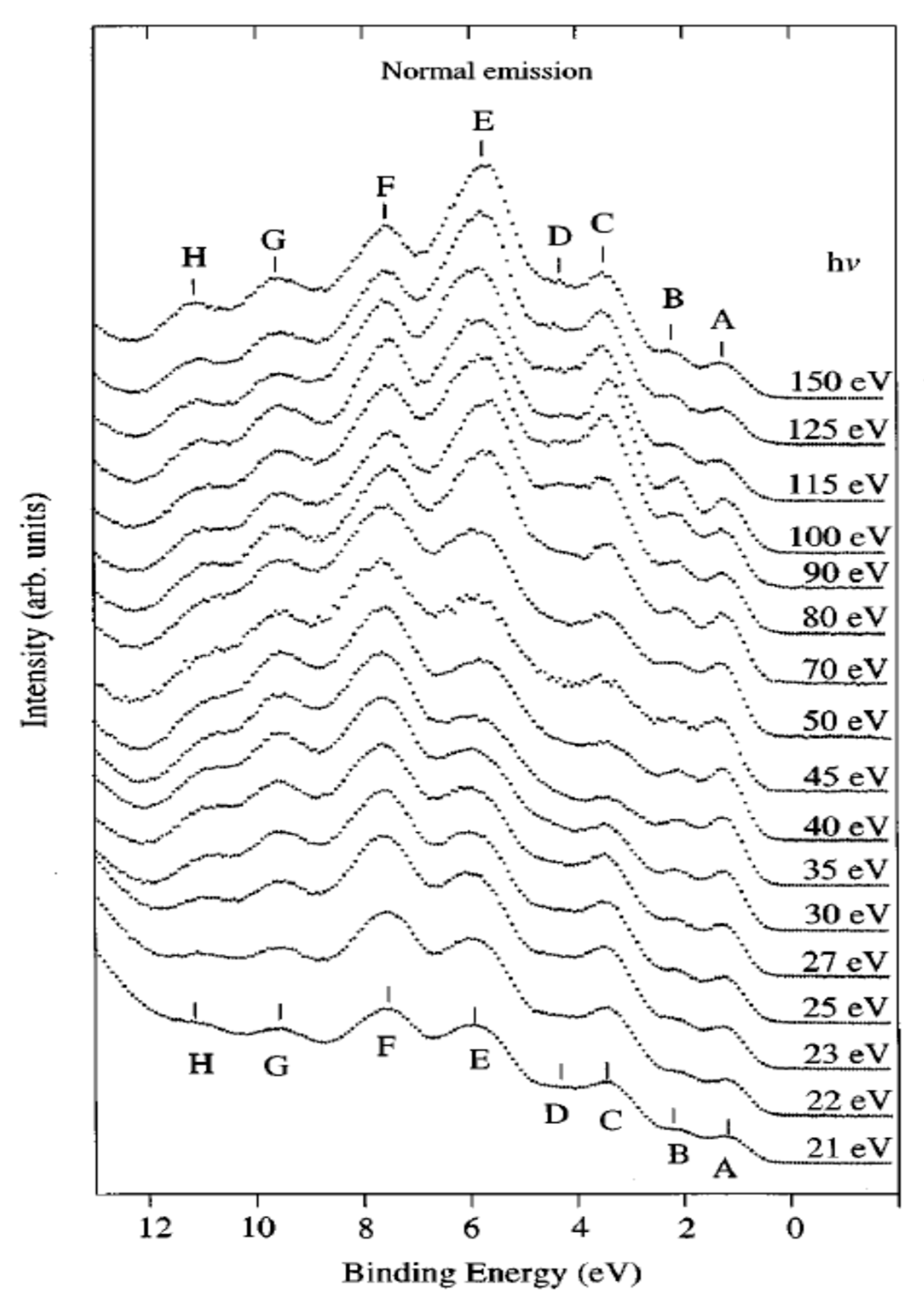
Shown in Figure 2 are ARPES spectra of the valence-band regime of an α-(BEDT-TTF)2I3 crystal recorded in normal emission, with different photon energies in the range 21–150 eV [55]. The spectra in this figure are normalized to the same height for visual clarity. Eight peaks labeled A–H can be seen in the valence-band regime shown in Figure 2, having binding energies between 1.2 and 10.9 eV relative to the Fermi level. The binding energies (BE) for peaks A–H are 1.2, 2.1, 3.4, 4.1, 5.7–6.0, 7.6, 9.6, and 10.9 eV, respectively. All peaks exist in the spectra except the peak D, which reduces to a shoulder when the excitation photon energy is greater than 70 eV or less than 25 eV. Within the experimental resolution, all peak BEs are independent of the exciting photon energy except that of peak E, whose dependence on the photon energy does not seem to be random. When the photon energy decreases from 150 ev to 50 ev, the peak shape changes gradually. Combined with the shift of the peak position when the photon energy is decreased below 70 eV, it is reasonable to expect that the peak consists of two closely lying structures. The change of the peak shape and the BE can be interpreted as the structure with the lowest binding energy dominating at photon energies above 70 eV, and the other structure is seen as a shoulder on the high BE side of the dominating structure. The structure with higher BE is dominating at lower photon energies, while the other is not identified when photon energies are below 30 eV. The ARPES data presented in Figure 2 gave no support for dispersing bands in the Γ-Z (kz) direction. Angle-resolved measurements along the a and b axis also gave no evidence that the structures closest to the Fermi level have any dispersion in the highly conducting plane. An upper limit of about 0.25 eV for the dispersion is set by the experiment [55]. The most probable explanations for the lack of any dispersion and the lack of a sharp Fermi edge despite α-(BEDT-TTF)2I3 showing metallic transport properties are correlation effects or the calculated narrow-gap semiconductor band structure [55].
Substantial band dispersion has been observed in other organic charge transfer conductors [59,60]. Tetrathiafulvalene-tetracyanoquinodimethane (TTF-TCNQ) is classified as an organic charge transfer conductor with a quasi-one-dimensional mixed valency segregated stack [60]. The incomplete charge transfer of 0.59 electrons from TTF to TCNQ causes the mixed valency in TTF-TCNQ. The ARPES measurements of single crystals were performed in the normal metallic state, i.e., above the charge density wave (CDW) transition temperature of 54 K for TTF-TCNQ [60]. TTF-TCNQ crystallizes in a monoclinic structure (Figure 3), space group P21/c, with lattice parameters a = 12.298 Å, b = 3.819 Å, c = 18.468 Å, and β = 104.46° [61]. The segregated TTF and TCNQ stacks run along the crystallographic b direction. The molecular planes are tilted by 24.5° (TTF) and 34.0° (TCNQ), with opposite signs regarding b around a. The two types of chains alternate along a but not along c. There are two TTF (TCNQ) chains with opposite tilting angles of the molecules within a unit cell, which leads to a herringbone type of arrangement.
The ARPES spectra of TTF-TCNQ are depicted in Figure 4 [60]. It shows angle-resolved measurements along the ΓZ direction, i.e., along the one-dimensional b axis, while data measured perpendicular to b was recorded and presented in the series of the right-hand panel. At the Γ point, two peaks are observed at around 0.19 eV (marked a in Figure 4) and 0.54 eV (marked b), respectively. From Figure 4, one can use dashed lines as a guide to the eye to track the dispersion of the two features, both approaching the Fermi energy at an angle around 7°. Two other features can be identified. Feature d seems to be split off feature b at the Γ point, and shifts to higher binding energy region with increasing angles, while feature c disperses away from the Fermi energy starting at an angle of about 7°. A completely different behavior is observed from data measured perpendicular to b in the right-hand panel. No dispersion is observed essentially, if one tracks peaks a and b again as a function of emission angle starting with the spectrum at the Γ point. The conspicuous dispersions along the one-dimension direction clearly show the long-distance order and substantial wave function overlap. On the other hand, these, along with the lack of any dispersion perpendicular to the 1D axis, truly reflect the electronic 1D character of the TTF-TCNQ surfaces [59]. A one-dimensional Hubbard model can be used to reconcile the observation of the dispersion [62]. Therefore, the data provides evidence for spin-charge separation where feature a represents the spinon and feature b the holon branch of the excitation spectrum [62].

3. Organic Semiconductors

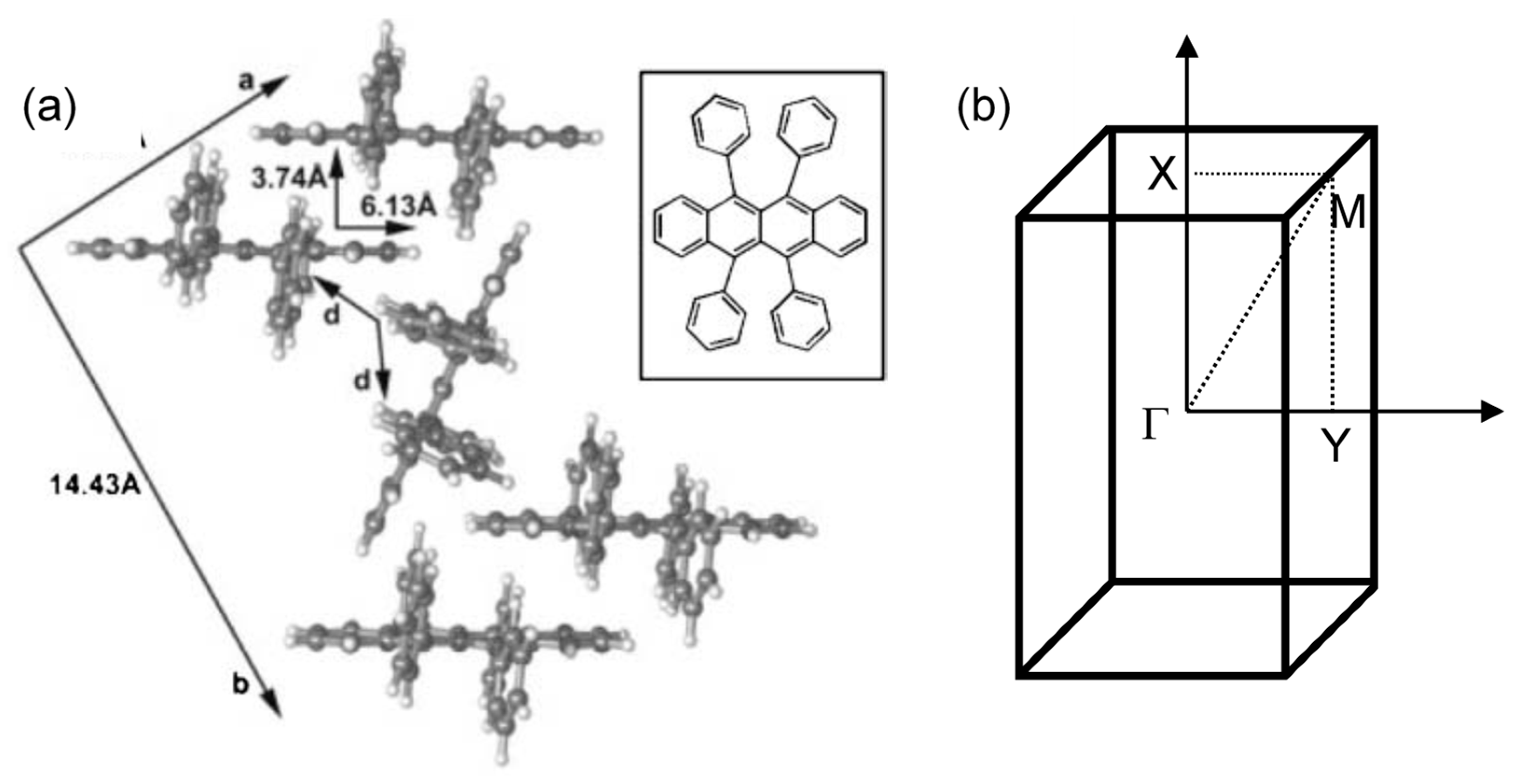
The interest in organic electronics was boosted with the discovery of conducting polymers in the early 1980s, which earned Alan Heeger, Alan MacDiarmid, and Hideki Shirakawa the Nobel Prize in Chemistry in 2000 [63], and was further stimulated when organic light-emitting diodes with quantum efficiencies attractive for consideration in real applications [64,65]. Rubrene is a tetraphenyl derivative of tetracene and has been shown by Podzorov et al. to have a field-induced hole mobility of over 15 cm2 V−1 s−1 at room temperature, with a novel device structure [66,67]. The molecular and crystal structure of rubrene are presented in Figure 5 [68]. Rubrene crystals are of the orthorhombic pyramidal point group with a well-developed face in (001) direction (a–b plane) and the slow-growing axis (c-axis) is normal to the top surface. Inside the crystal the rubrene molecules are in a lying down phase with long axes all embedded in the a–b plane. Figure 5b shows the reciprocal lattice of the rubrene single crystal unit cell, where the ΓX, ΓY and ΓM direction corresponds to the a-axis, b-axis and the diagonal direction, respectively.
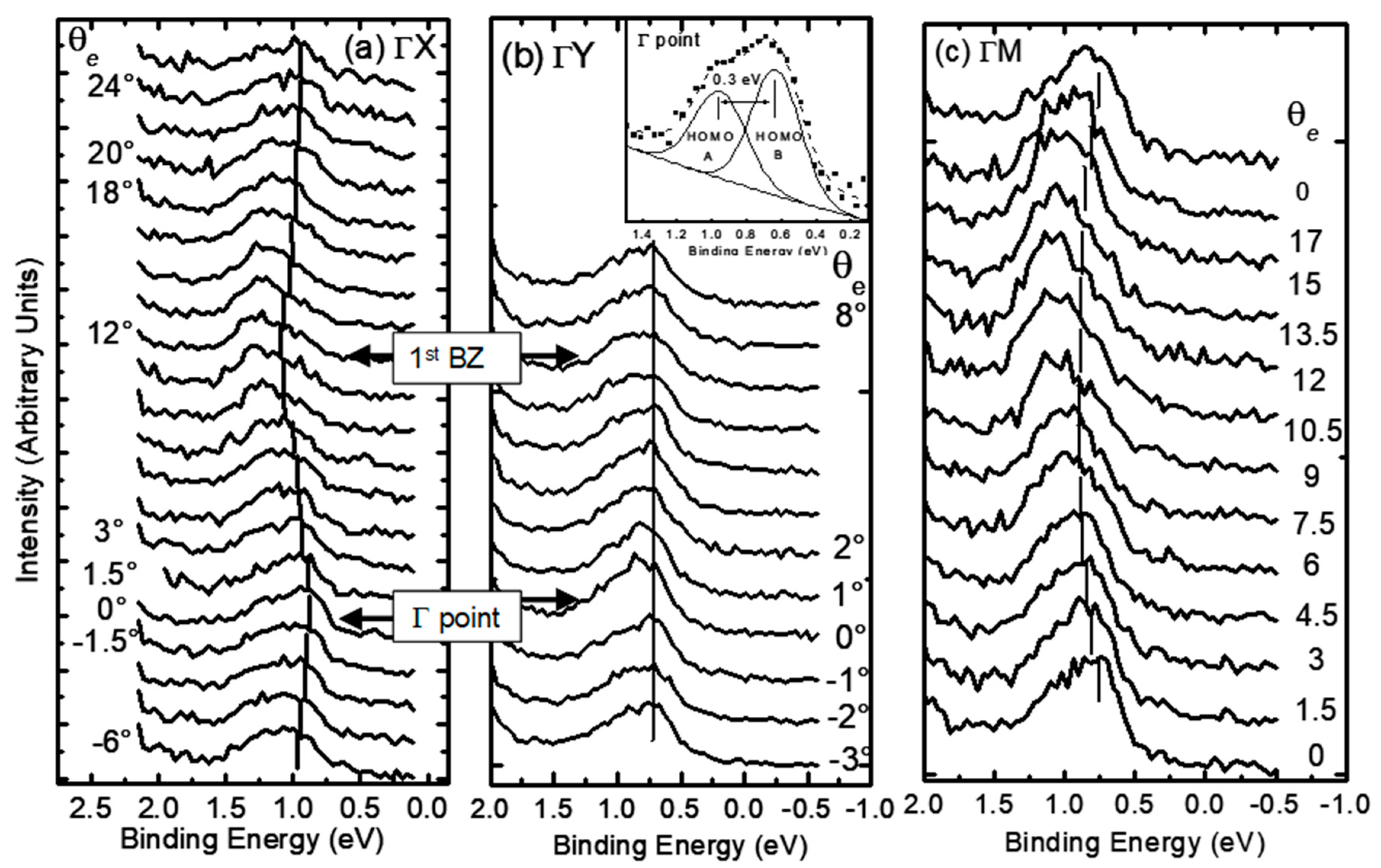
Figure 6a–c respectively show the ARPES spectra of rubrene single crystal surface measured along the ΓX (a-axis), the ΓY (b-axis) and the ΓM (diagonal) directions, respectively, as a function of electron emission angle θ. The highest occupied molecular orbital (HOMO)-derived features are located at a binding energy of about 1 eV. An asymmetric line-shape can be observed at the Γ point (θ = 0°), which indicates a splitting of two peaks. The spectrum was fitted by Gaussian peaks after the careful subtraction of a polynomial background to confirm the presence of two HOMO-derived bands is shown in the inset of Figure 6b. It is clear that there are two peaks of HOMO feature in the ARPES spectra, HOMO-A at higher binding energy and HOMO-B at lower binding energy, separated by ~0.3 eV. Other organic molecules, such as pentacene, have also observed such splitting [69], which has been theoretically predicted, due to the presence of two nonequivalent molecules in the herringbone structure in a unit cell [70,71]. Taken with a higher resolution, Figure 6a displays that, as θ increases, both peaks move towards higher binding energy and reach the maxima at about 12°, which corresponds to the boundary of the first BZ in the ΓX direction (a-axis). However, the shifts for HOMO-A and HOMO-B are ~0.15 eV and 0.25 eV respectively, which are not identical. Both peaks start to shift back towards lower binding energy as θ is increased beyond the boundary of the first BZ, reaching the values measured at the Γ point. The other side of the Γ point (negative θ) also demonstrated similar behavior. These results indicate a symmetry around both the BZ boundaries and the Γ point. Interestingly, the spectra taken in ΓY direction (b-axis) seem to be quite different from obvious dispersion observed in ΓX direction. As shown in Figure 6b, the two HOMO-derived bands remain almost intact in terms of positions as well as intensities, which clearly indicates that the band dispersion of rubrene single crystal has a strong anisotropic behavior in the a–b plane of the unit cell. Finally, the ARPES measurements have also been conducted along the diagonal direction ΓM, as shown in Figure 6c. The result is similar to that of the ΓX direction, except that HOMO-A and HOMO-B have a slightly smaller dispersion of 0.15 eV and 0.23 eV, respectively.
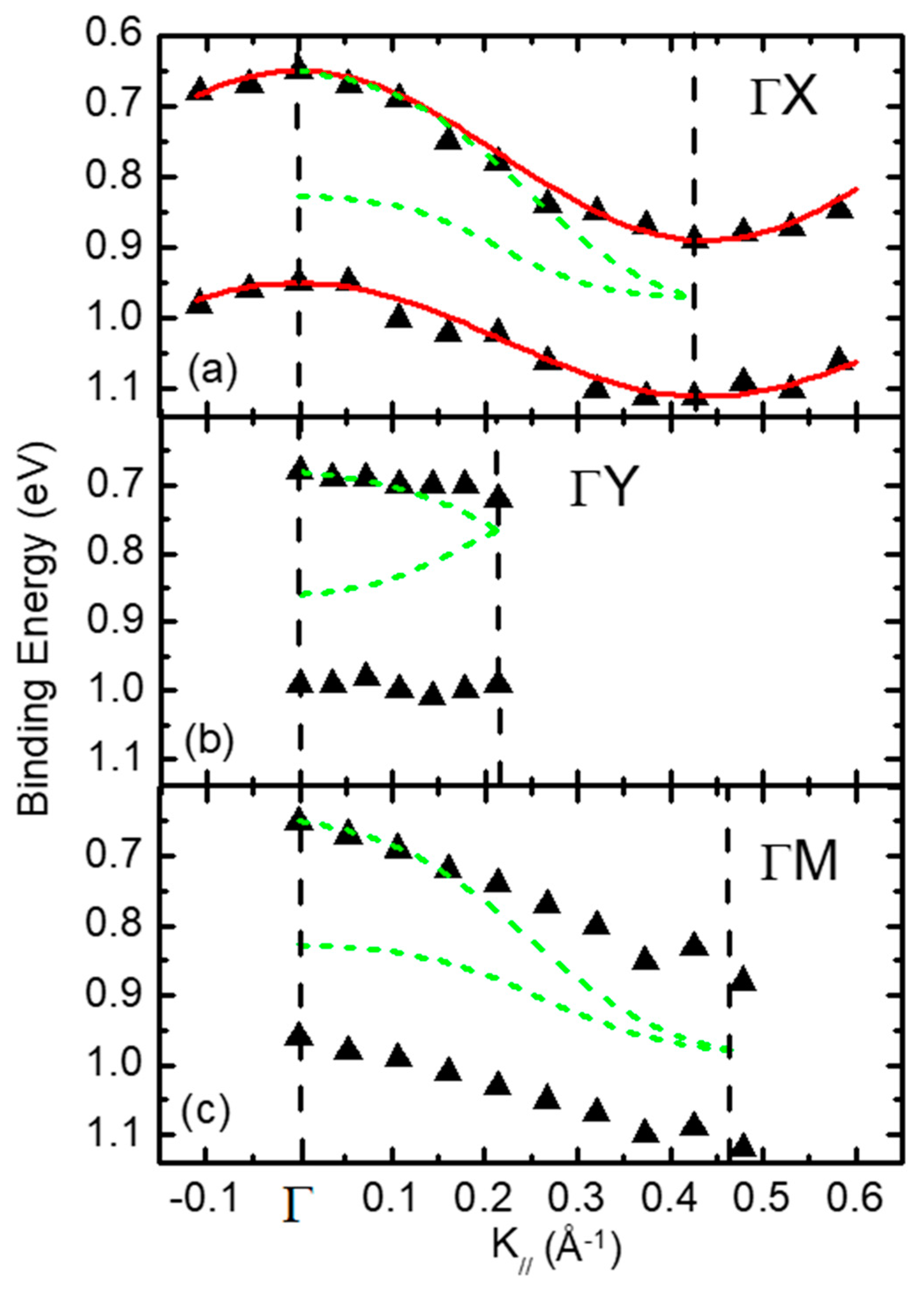
The experimentally measured energy dispersion curve of the two HOMO-derived bands of rubrene single crystal are shown in Figure 7. The binding energy of HOMO-A and HOMO-B is plotted as a function of k// presented in the inset of Figure 6b, the momentum parallel to the sample surface, along the ΓX, ΓY and ΓM directions. The dashed lines represent the Γ point and the first BZ boundaries for all three directions. The data collected along ΓX direction show great symmetry at both the Γ point and the BZ boundary. A strong anisotropic dispersion in the a-b plane can be observed for both bands. For instance, the dispersion width of the lower binding energy HOMO-B can be estimated to be about 0.25 eV in the ΓX direction, while the dispersion width of the same peak is only 0.05 eV; almost negligible in the ΓY direction. The anisotropic behavior of the measured band dispersion in the a-b plane is consistent with the expectations from theoretical calculations [72,73], as well as the mobility measurement from the single crystal field effect transistors [74]. The rubrene crystal structure can speak to such anisotropic behavior. The rubrene molecules are stacked with a certain displacement along the long molecular axes in ΓX direction (a-axis in Figure 5a). From theoretical calculations, it has been showed that the stacking distance of the molecules coincides with the calculated extreme in the oscillation of the HOMO transfer integral [73], which provides an efficient overlapping of the π-orbitals, thereby larger band dispersion. On the other hand, the adjacent molecules are more than 14 Å apart (see b-axis in Figure 5a) in the ΓY direction, which avoids any possible π-overlapping, causing a very small dispersion width. Interestingly, the dispersion widths measured along the diagonal direction (ΓM) are very close to that of the ΓX direction for both bands. This indicates that, although it is difficult to perform the direct band transport along b-axis, the charges may still make their way through the diagonal direction. The second issue to note is that the dispersion widths of the two HOMO-derived bands are different. HOMO-B shows a larger dispersion width in all measured directions at lower binding energy. For example, the dispersion widths are estimated to be 0.25 eV and 0.15 eV for HOMO-B and HOMO-A in the ΓX direction, respectively. The theoretical calculations have also predicted the discrepancy in the dispersion width of the two bands [72,73].
The dashed lines in Figure 7 represent the band structure calculations from Ref. [72]. Although there are general similarities between the measured and calculated band dispersion, some significant differences can also be noted here. First of all, the measured energy splitting of the two bands is 0.3 eV at Γ point, almost twice of that in the density functional theory (DFT) calculation. In addition, the dispersion widths obtained from the ARPES measurements are smaller. In the ΓX direction, for instance, the maximum energy dispersion measured from the experimental data is 0.25 eV, which is significantly smaller than 0.32 eV from the theoretical prediction [72]. The smaller dispersion measured in the experiment may indicate a weaker interaction between the π-orbitals of the adjacent rubrene molecules than what was theoretically predicted. Finally, as required by symmetry, the two bands merge into one at the BZ boundaries in the theoretical calculations. However, this is not observed in the ARPES data. The spectra demonstrate a feature of distinguishable asymmetry in the HOMO region at the BZ boundaries, as shown in Figure 6, which suggests that there are two HOMO-derived features at this point. In fact, for pentacene thin film, it has been reported that similar discrepancies between the ARPES data and the theoretical calculations [69]. The origin of the observed discrepancies is poorly understood at this time. A similar ARPES experiment with practically identical spectra was reported, which deduced a different band structure by introducing band crossing [75,76].
Another measurement on single crystal rubrene was carried out with ARTOF electron energy analyzer, and again, consistent results were observed [77]. There are two features at Γ point and BZ boundary from the raw data shown in Figure 6. Several different ways have been tried to fit the experimental data beside that shown in Figure 7. The first attempt was fitting with another introduced broad peak, which represented the non-dispersive feature induced by possible defects or impurities on the crystal surface. However, except that there was a slight increase in the separation between the two bands, the results of the analysis turned out to be the same. A third peak had to be introduced to complete the fitting if the two bands are overlapped intentionally at the BZ boundary. However, there would be two non-dispersive features as well as one dispersive feature with a bandwidth of 0.4 eV in this case [77].
A key factor to understand the transport properties of rubrene single crystal is the measured band dispersion curve. The solid line in Figure 7a represents a detailed analysis of the ARPES data, using a simple tight-binding (TB) model that has already been successfully used to explain band dispersion in organic materials [78,79,80]. The dispersion relation is then described by the following expression:
EB(k//) = Ec − 2t cos(ak//)
where t is the transfer integral, a is the lattice spacing of the corresponding direction, and Ec is the binding energy of the band center. The experimental data can be fitted very well by the TB model, as shown in Figure 7. The fitting produces a value of the transfer integral t of 0.06 eV, which is comparable to other organic single crystals [8,79]. For a broad band transport, the band width is much larger than kBT (~30 meV), and the drift mobility of the hole is given by
μ = /mh*
where mh* is the effective mass of the hole, and τ is the relaxation time due to the scattering. Without degeneracy, the requirements of the uncertainty relation in the usual semiconductor theory can be expressed as
3 2 k B T > τ = e m * μ
If the mobility μ is in unit of cm2V−1s−1, then Equation (9) implies that
m * m 0 > 2 3 e 300 m 0 k B T μ 20 μ 300 T
where m0 is the free electron mass [81,82]. Note that the above equations are only valid if m*/m0 is not too large, which means that bandwidth should be much larger than kBT. Equation (10) can be simplified for room temperature in the case of single crystal rubrene as
μ > 20 m 0 m * ( cm 2 V 1 s 1 )
Hence, the estimation of the effective mass from the dispersion curve may be able to obtain the lower limit of the hole mobility. According to the fitting, the effective mass of HOMO-B band is derived to be 1.3 m0 in the ΓX direction. This is in sharp contrast to the general picture of polaronic transport in normal organic materials, which is characterized by a dramatic enhancement of the effective mass as a result of strong coupling between the carriers and the local lattice deformation. The theoretical calculations and the infrared spectroscopy studies have also predicted the presence of the light holes [72]. The lower limit of the hole mobility can be estimated to be around 15 cm2V−1s−1, based off the derived mh*. This value is comparable to the results measured from the transistor experiment [66].
A major challenge to perform the photoemission measurements on organic single crystals is the charging effect induced by the limited conductivity in organic crystals of a few μm thick. The charging effect induced by the limited conductivity in organic crystals with a thickness of a few μm is a major challenge to conduct the photoemission measurements on organic single crystals. The illumination of the sample surface with visible light can solve this problem. The intensity of the light has been adjusted, so that the spectra obtained after UV exposure for two hours remain the same as that of the fresh surface. Many other groups have also reported the increase of the conductivity under illumination in the transport measurements. Such an increase has been explained by the elimination of the carrier traps by the photo-excited charges [83,84].
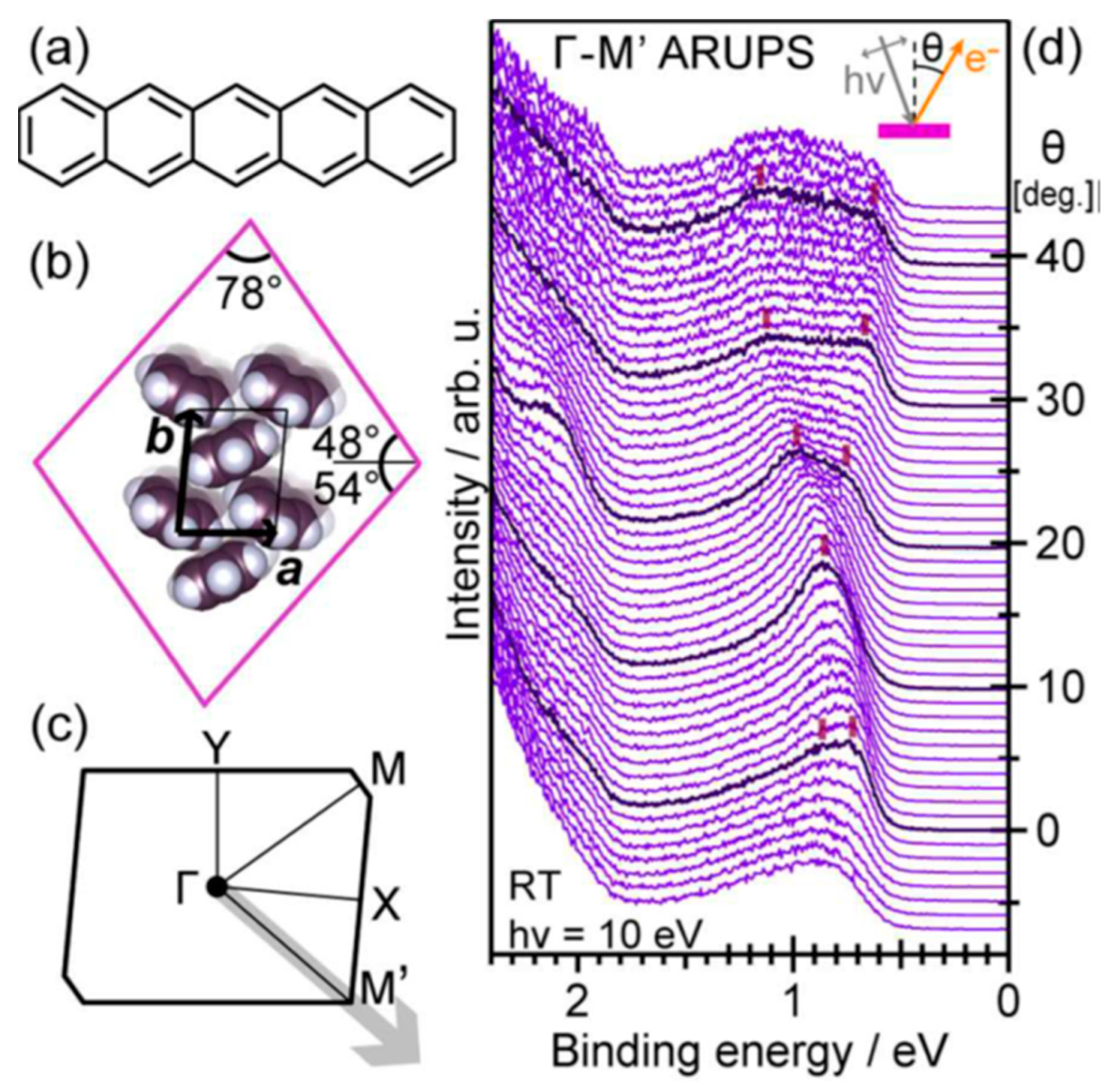
Pentacene is one of the most well-studied organic semiconductor materials because of its high hole mobility of 1.5 cm2 V−1 s−1 in thin films and over 10 cm2V−1s−1 in single crystals, indicating that the transport mechanism should be considered as bandlike rather than intermolecular hopping [18,85,86]. The band structure of single crystal pentacene and a very similar material picene have been investigated with ARPES [85,87]. The molecular structure of pentacene is shown in Figure 8a, which can be taken as five benzene rings fused together side by side [85]. The anisotropic character of the crystal shape determines the orientation of the pentacene single crystal, as shown in Figure 8b [85]. Figure 8d shows the ARPES spectra of pentacene taken at RT, where the photoelectron emission angle was varied along the ΓM direction of pentacene (Figure 8c), which has theoretically predicted the widest energy dispersion [88]. The abscissa is taken on BE with respect to the Fermi level. In the surface BZ, the electron emission angles θ of 0° and ∼33° correspond to the points Γ and M respectively. In the BE range of 0.5–1.5 eV, spectral profiles show characteristic transformations with respect to θ, which are ascribed to the valence band (highest occupied states) of pentacene. At BEs <1 eV, two spectral components are resolved in close proximity to each other under the normal emission condition (θ = 0°). These components coalesce at around θ = 10°, split into two again by θ = 20°, and are further separated at larger θ by changing the emission angle. This variation reflects the energy dispersion of the valence bands of the pentacene.
Figure 9a demonstrates the E−K plane dispersion from the ARPES spectra in Figure 8d. It also shows that the electronic band structures are replicated as an undulation of the photoelectron intensity [85]. The shape of the valence-band structures revealed by ARPES measurements reproduces the theoretical prediction very well [88]. In Figure 9b, the E−K dispersion relations of the pentacene single crystal valence bands were mapped, and the energetic positions are determined by curve fitting of the individual ARPES spectra, corresponding to the respective θ. There are three spectral components which are resolved from the spectra in the valence-band region at the Γ point. The lower component of a dispersionless character may be attributed to the inelastic scattering of photo-electrons by impurities, while the upper two components are ascribed to the two valence bands originating from the HOMOs of the two pentacene molecules in the unit cell of pentacene [77]. A simple one-dimensional TB approximation can well reproduce the E−K dispersion of the first and second bands. The VBM is located at the M point rather than Γ, which agrees with the theoretical work [88]. Notably, the trend of the present dispersion relation, namely, the expansion of the energy split of the two bands, is in contrast with that of the thin-film phase of pentacene when moving toward the edge of the surface BZ along its diagonal direction [69]. Again, it shows that one must be very careful when interpreting the band dispersion features observed in thin film geometry.
Many organic semiconductors show indiscernible dispersion because the Van der Waals crystal nature and weak electron wavefunction overlap, as well as the strong electron-phonon coupling [43]. Perylene (C20H12) is an arene compound that has two polymorphs of α-phase and β-phase [89]. Perylene derivatives can be found in commercial dyes and light emitting devices. Perylene can also form charge transfer co-crystals with tetracyanoquinodimethane that have tunable optical and electronic properties, as observed in field effect transistor applications [89].
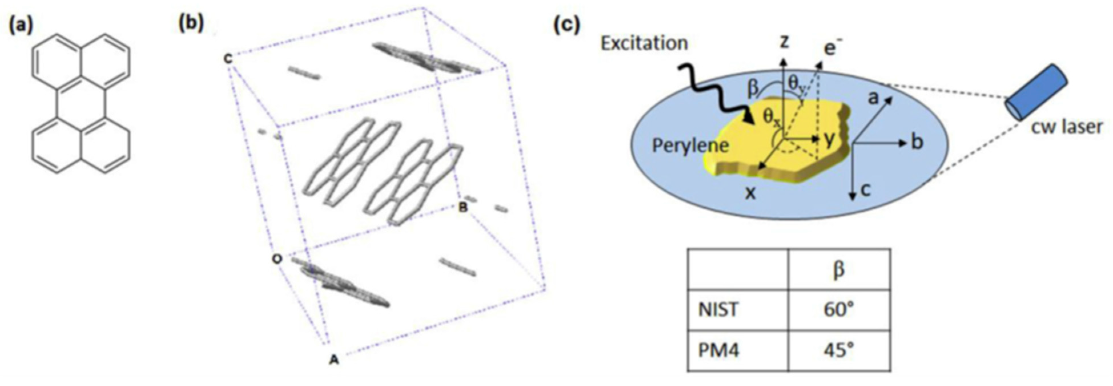
The perylene molecule skeletal structure is shown in Figure 10a,b, which show the unit cell, containing pairs of perylene molecules that are stacked in a sandwich herringbone motif [90]. The crystal structure is monoclinic with lattice parameters a = 1.027 nm, b = 1.081 nm, c = 1.118 nm, α = 90°, β = 100.8°, γ = 90°. It was not possible for the ARPES measurements to identify the relative orientation (i.e., a and b axes) of specific crystals, because of the crystal size. Figure 8c demonstrates the geometries of the photon excitation source and electron energy analyzer used for measurement at beamline PM4 of the BESSY II synchrotron facility (Helmholtz-Zentrum Berlin) and a He ultraviolet light source at National Institute of Standards and Technology (NIST); the normal sample is oriented along the electron analyzer at both locations. Figure 10c also shows the bipolar coordinate system used for the presentation of the ARTOF data.
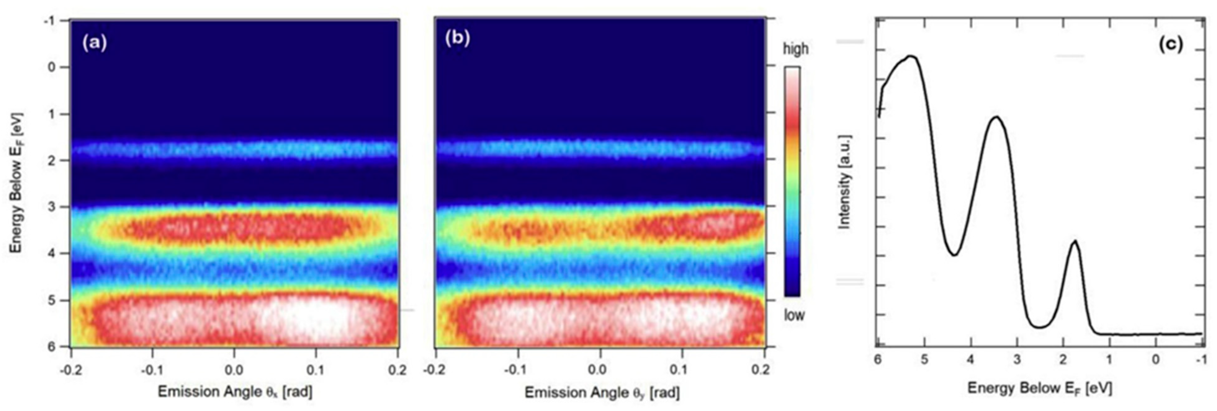
The measured photoemission intensities of several of the highest occupied levels of α-perylene are illustrated in Figure 11a,b, as a function of photoelectron emission angles in θx and θy, as demonstrated in Figure 10c. The spectra measured in θx and θy emission angles (in Figure 10a,b) are combined and demonstrated in Figure 11c. In Figure 11c, the center of the HOMO “band” is found to be 1.75 eV ± 0.05 eV below the Fermi energy in all available emission angles (in Figure 10a,b). The representative 2D plots in Figure 11a,b indicate that the identification of the presence or absence of band dispersion in the α-perylene over the accessible angular range (corresponding to ±0.8 Å−1) is inconclusive, although there are small variations in the intensity and width of the HOMO and HOMO-1 levels with emission angle in the ARTOF measurements. The average maximal “bandwidths” can be estimated at around 0.4 eV ± 0.1 eV and 0.7 eV ± 0.1 eV for the HOMO and HOMO-1 levels, respectively, as determined from the fullwidth at half maximum at various emission angles between −0.1 radians and 0.1 radians. An upper limit is set for any band-like dispersion in the α-perylene electronic structure [90].
Calculations of the electronic structure of α-perylene indicated that three bands with an molecular orbital character contribute to the HOMO region [91]. According to those results, the maximum width of the frontier α-perylene HOMO can be estimated to vary from 0.25 eV to 0.08 eV across the Brillouin zone. Compared to other organics such as pentacene or rubrene, it is somewhat weakly dispersive. The HOMO-1 “bandwidth” is found to be around 0.8 eV and this agrees well with the measured ones shown in Figure 11 [90,91].

4. Organo-Metallic Perovskite Charge Transfer Crystals

Perovskite is the appellation for any materials that have the same crystal structure as calcium titanate, namely, ABX3. Perovskites are originated from a cubic structure, where A is commonly a large cation at the body center of a cubic unit cell, B a smaller metal atom at the 8 corners of the cube, each contributing 1/8 of an atom to the unit cell, and X anions are at the middle of the 12 edges of the cube, each contributing 1/4 of an atom to the unit cell [92,93,94]. Some perovskites are reported as non-cubic. For example, CsPbI3 has an orthorhombic structure at room temperature [95]. The crystal structure of BiFeO3 multiferroic thin film is monoclinic in contrast to bulk, which is rhombohedral [96]. Organo-metallic halide perovskites, with organic A cations such as methylammonium (MA = CH3NH3+) or formamidinium (FA = CH(NH2)2+), B of group 14 metal Pb or Sn, and X of halogen elements Cl, Br, and I.X3, which are tetragonal, have exhibited important and unique properties. In just about a decade, maximum power conversion efficiencies (PCEs) have evolved from 3.8% [97] in 2009 to 23.34% [98] in 2018. Monolithic tandem c-Si/perovskite solar cells have achieved high efficiencies above 27% [99], with a potential of above 30% [100]. Other applications of organo-metallic halide perovskites beyond just photovoltaic devices include photo detectors [101], light emitting diodes (LED) [102] and lasers [103].
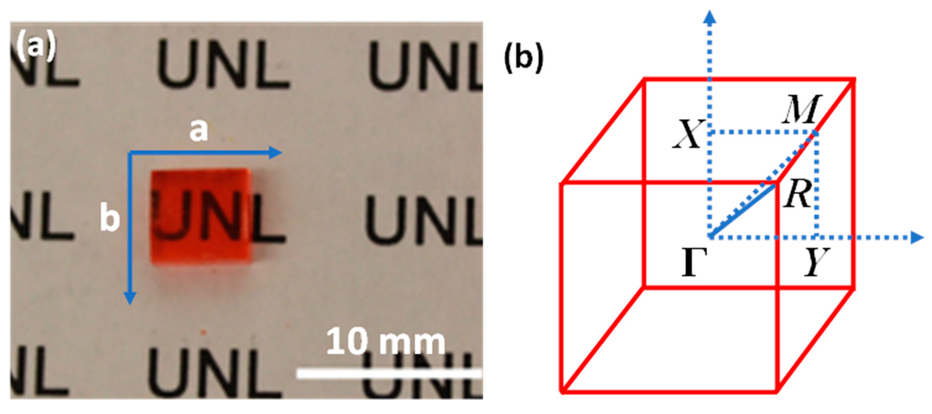
Figure 12a shows an as-grown methylammonium lead bromide (MAPbBr3) single crystal. The reciprocal lattice of the crystal unit cell is illustrated in Figure 10b, where ΓX, ΓY, and ΓM directions correspond to the a-axis, b-axis (Figure 12a) and the face diagonal direction, respectively. The reciprocal lattice is often used to represent the Fourier transform of the crystal lattice in k-space [1]. Because of the restriction of the intrinsic (001) cleavage plane of the perovskite material, ΓR direction could not be evaluated. ΓX, ΓY and ΓZ directions are all degenerate due to crystal symmetry [104].
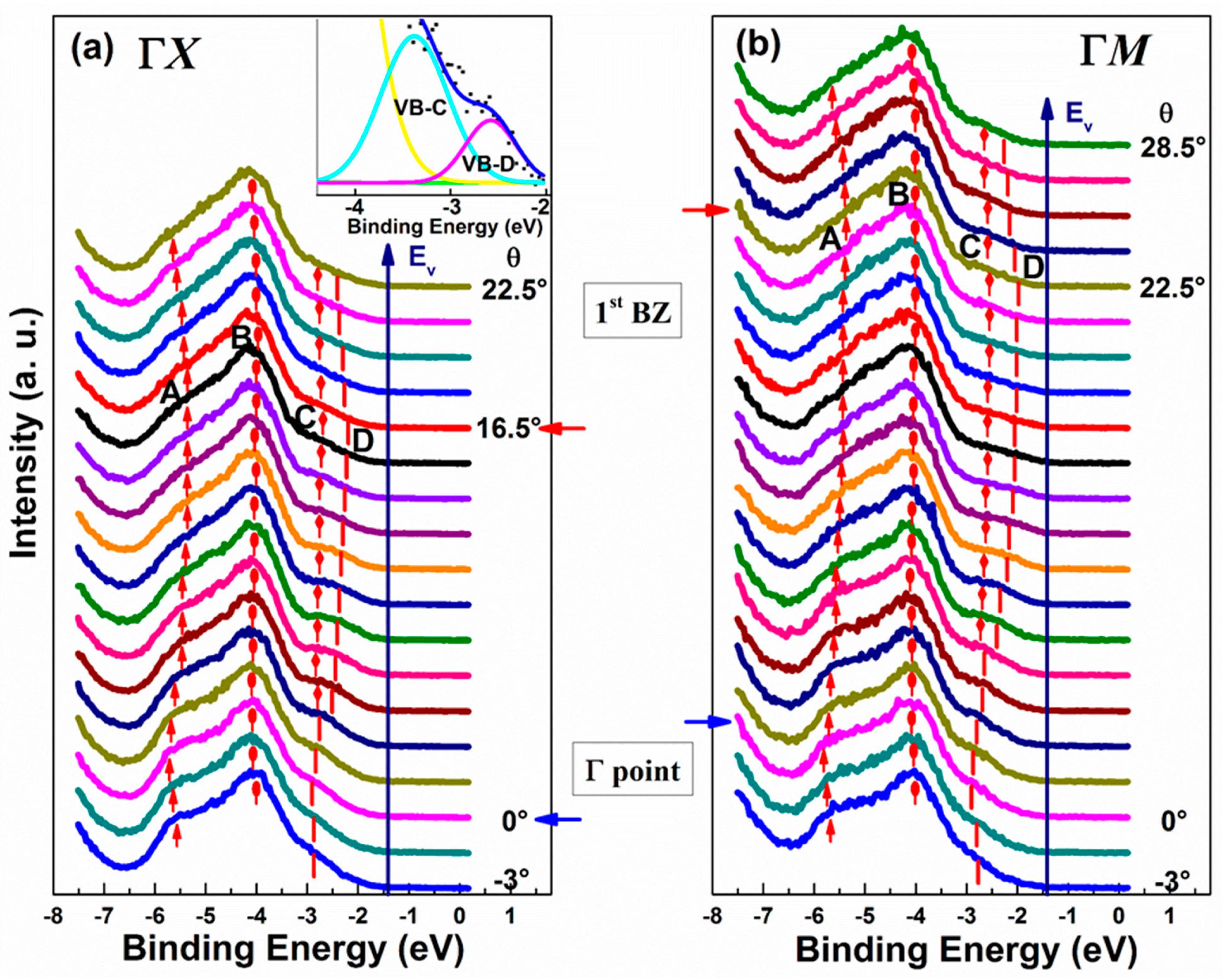
Angle-resolved energy distribution curves (EDCs) of overall valence band as a function of electron emission angle θ relative to the surface normal measured along ΓX and ΓM directions, respectively, are shown in Figure 13a,b [104]. Four Gaussian peaks of VB-A, VB-B, VB-C, and VB-D are used to fit the normalized spectra. One detailed analysis is presented in the inset of Figure 13a. A structured and angle-dependent valence-band emission can be seen in both series of spectra. For both the ΓX and ΓM directions, as θ increases, all the peaks move towards a higher BE until they reached the Γ point (θ = 0°). After passing through the Γ point, the peaks show an upward dispersion and reach the minima at around 16.5° and 22.5° in ΓX and ΓM directions, respectively. The peaks present an upward dispersion and reach the minima at around 16.5° and 22.5° in ΓX and ΓM directions, respectively, after passing through the Γ point. This minimal position corresponds to the boundary of the first BZ in each direction. The shifts are 0.48 eV, 0.18 eV, 0.40 eV and 0.98 eV for VB-A, VB-B, VB-C, and VB-D in ΓM direction; and 0.41 eV, 0.18 eV, 0.20 eV, and 0.73 eV in ΓX direction, separately. It is noticeable that the shifts are somewhat stronger along ΓM direction. All the peaks start to move back toward higher BE again as θ increases beyond the 1st BZ boundary. These results suggest the symmetry around the BZ boundaries and the Γ point [104].
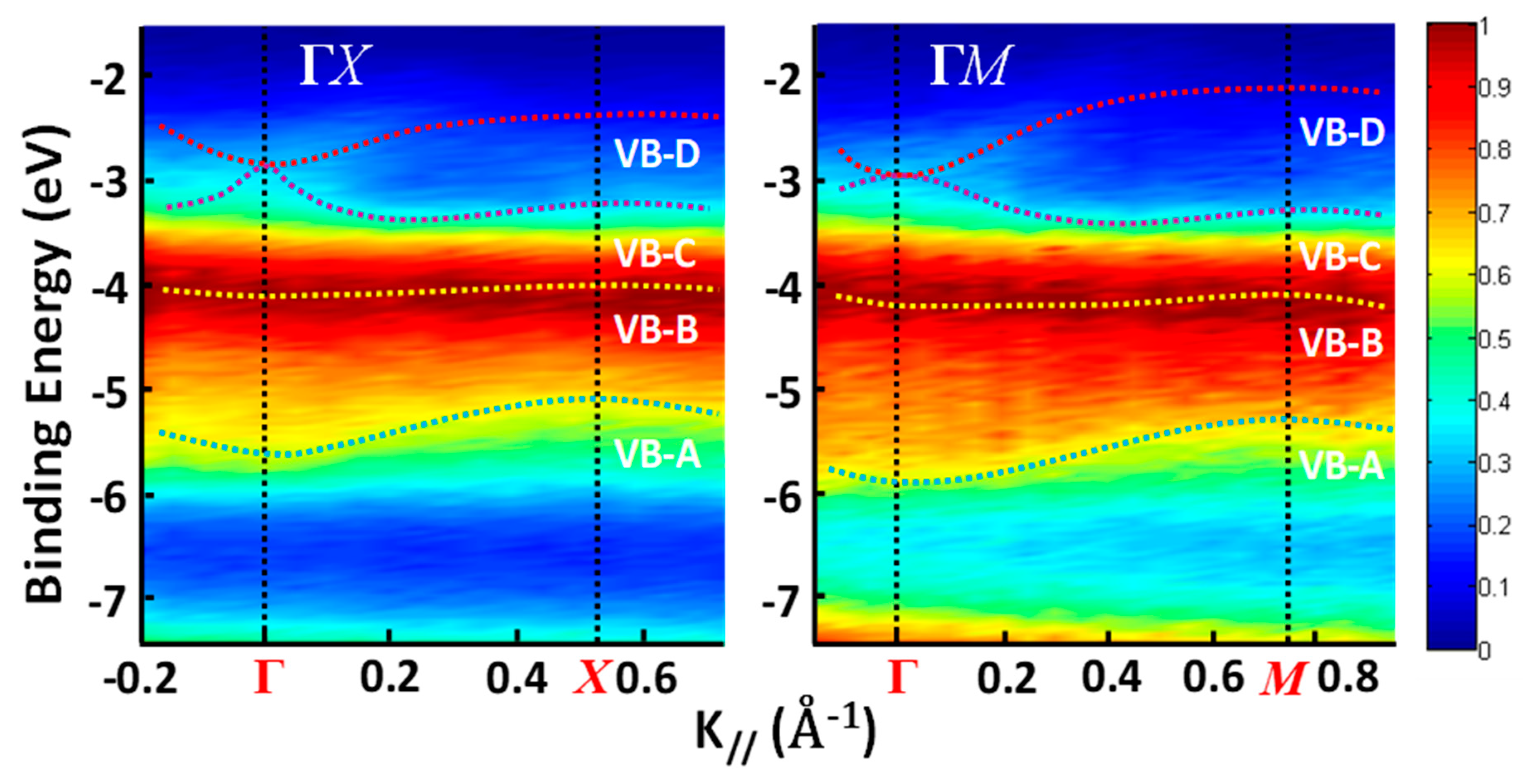
Figure 14 shows the MAPbBr3 energy dispersions of the four valence bands as a function of k along ΓX and ΓM directions. Figure 14 shows the energy dispersions of MAPbBr3 of the four valence bands as a function of k along ΓX and ΓM directions. The data points are the fitted peak centers of the four valence bands at each angle calculated in k-space. However, in Figure 14, the intensities of the kinetic energy calculated in k-space are represented in different colors. The dispersion curves therefore were fitted based on the color regions. Apparently, the two fitting results are very similar [104].
By contrast, the 1st BZ boundary has a peak energy of ~ −2.18 eV at the X point, which is lower than that of ~ −1.94 eV at the M point. The experimental results are ~ −0.90 eV and ~ −1.70 eV at the M point and the X point, respectively, which agree well with the first-principles calculations [105]. It indicates that the VB is a mixture of Pb-s and Br-p orbitals [105,106], and the band features are mostly contributed by the Br-p orbitals [105,106]. Interestingly, the VBM split into two bands of VB-C and VB-D, which are at about k = 0.14 Å−1 and ~0.24 Å−1 for ΓX and ΓM directions, respectively. The comparison of the DFT results from Jishi et al. [105] can explain this band splitting. From the calculation, the bandgap of the cubic MAPbBr3 single crystal is 2.23 eV and occurs at point R (1/2, 1/2, 1/2) in the BZ. It is not possible to compare the VBM dispersions in the ΓR direction, since the crystal cannot be cleaved along this direction. However, as presented in Figure 13a, the VBM dispersion in ΓX direction is ~0.56 eV, which is smaller than the measured value of 0.73 eV. The VBM dispersion in ΓM direction is ~1.45 eV, which is greater than the measured one of 0.98 eV, as shown in Figure 13b. The second and third valence bands are very close to each other based on the band structure calculation. They almost have the same value, with the VBM at the vicinity of the Γ point in both directions. The average dispersions of the two bands are ~0.14 eV and ~0.2 eV, which are comparable with the 0.20 eV and 0.40 eV of VB-C in ΓX and ΓM directions, respectively. As a result, these two bands could contribute to the VB-C, and share the same k value with VB-D near the Γ point [104].
The calculated value of the hole mobility from the band structure is similar to some reports, which are from 19.4 to 56.1 cm2V−1s−1 by photoluminescence measurements [107], and 24.0 cm2V−1s−1 from dark current-voltage measurements [108]. Other results such as 217 cm2V−1s−1 and 206 cm2V−1s−1 are from time-of-flight (TOF) measurements [101], which demonstrate larger values than the measurement results. Shi et al. [109] used Hall effect measurements and TOF measurements to obtain the mobility of the same sample. The results are 20 to 60 cm2 V−1 s−1 and 115 cm2 V−1 s−1, respectively. The higher TOF measurement than those from other methods can be attributed to the distribution of mobility. In other words, TOF measurement gives the highest mobility to carriers. Meanwhile, the DFT results indicated a necessity to have the largest VBM dispersion for the ΓR direction, which may result in the lowest effective mass and highest hole mobility. Refrained by the restriction of the cleaving technique, the dispersions along this direction could not be measured. It is also possible that the hole mobility is underestimated because it is too complicated to fully present the structure of perovskite single crystal with the TB approximation fitting.
In Niesner et al.’s work, they found out the giant Rashba splitting in MAPbBr3 single crystals and confirmed the presence of the strong spin-orbit coupling (SOC) in both orthorhombic and cubic phases [110]. Normally, the presence of SOC is stronger in conduction band than in valence band [105,111,112]. However, in both ΓX and ΓM directions, they did not observe a clear Rashba splitting around the VBM or its effect on the largest band dispersions. The lower limit drift mobility of the holes in perovskite single crystals were revealed by these observations. In practical cases, because of the interfacial characteristics between perovskite and other layers, the transport behavior of the real devices may be more complicated. The effective mass and carrier mobility also play a significant role for a fair evaluation for the possibility to apply the perovskite material as a future channel material, to achieve high speed performances in field effect transistors [104].
More recently, ARPES measurements [113] on prototypical organo-metallic perovskites (MAPbBr3 and methylammonium lead iodide (MAPbI3)) were performed and compared, that revealed the band dispersion in two high-symmetry directions and identified the global valence band maxima. Given these benchmark data, photoemission spectra from polycrystalline thin film samples were constructed, and the consistency of relating the energy level alignment was discussed in perovskite-based photovoltaic and optoelectronic applications with their functional parameters [114,115,116].
Figure 15a–c displays the as-obtained ARPES spectra as a function of k for MAPbBr3 and Figure 15d–f demonstrates that for MAPbI3 [114]. In order to improve the visualization of electronic bands and their dispersion, the 2D curvature method was used to analyze the ARPES spectra [117]. These treated ARPES data seem sharper, which helps to track the k dependent peak positions and creates more space for a straightforward comparison with the DFT-calculated band structure. In ARPES measurements, the electron wave vector component perpendicular to the surface (k) is not conserved, and the k resolution is dependent on the photoelectron kinetic energy. Therefore, one needs to take into consideration whether the measurements can meet the experimental conditions within the so-called band structure regime (i.e., information about the k position within the BZ is retained), and DFT calculations can have a more accurate use in assigning the probed directions. For both perovskite crystals, it was shown that there was a wide dispersions of the top valence bands (VBs) along the two principal directions. In accordance with the calculated band structures when dispersion along ΓX is minimal, such observation can be matched best by assuming these to be the XM and XR momentum directions of the bulk BZ. In fact, good overall agreements are clearly presented between theory and experiment (see Figure 15a–c), by overlaying the calculated bands along the XM and XR directions with the photoemission data. According to the above assignment of directions, the determination of a lattice parameter can be attributed to the periodicity of the ARPES data from MAPbBr3 in Figure 15a, aARPES = 5.56 ± 0.29 Å [114].
Hole effective mass is one key parameter for charge transport properties, mh*, which is deduced for MAPbBr3 to be 0.25 ± 0.08 m0 near R (in the XR direction), and 0.30 ± 0.15 m0 near M. For MAPbI3. Due to the feature of the structure where the top of the VB would appear along ΓZ, and the intensity was not observed, it is not apparent to see the notable contributions of the tetragonal structure to the photoemission spectra. The lattice parameter determined from the periodicity along XM amounts to 5.97 ± 0.18 Å, which is perfectly correspondent with the lattice parameter of the cubic phase. In line with the theoretical results, the VBM is found to be located at R [118]. Moreover, another consistent with the calculated ones for the cubic structure (0.6 and 1.1 eV, respectively) is clearly seen, with the topmost VB widths being 0.6 eV (XM) and 1.0 eV (XR). Differences between ARPES and DFT are revealing for some of the higher BE bands. Most notably is that the experimental data does not show the (as can be seen best in the curvature spectra) four calculated bands just below the top VBs. It remains unknown why this deviation occurs. One of the possible reasons is related to matrix element effects given the polarization of the incident light, which can potentially modify the measured photoelectron intensity [119]. While calculations were performed for an infinite bulk, a structural difference may also appear between the sample surface and bulk as the cubic structure could be confined to the near-surface region in experiment. Other measurements, however, seem not to suffer as much from the above-mentioned effects [115,116].
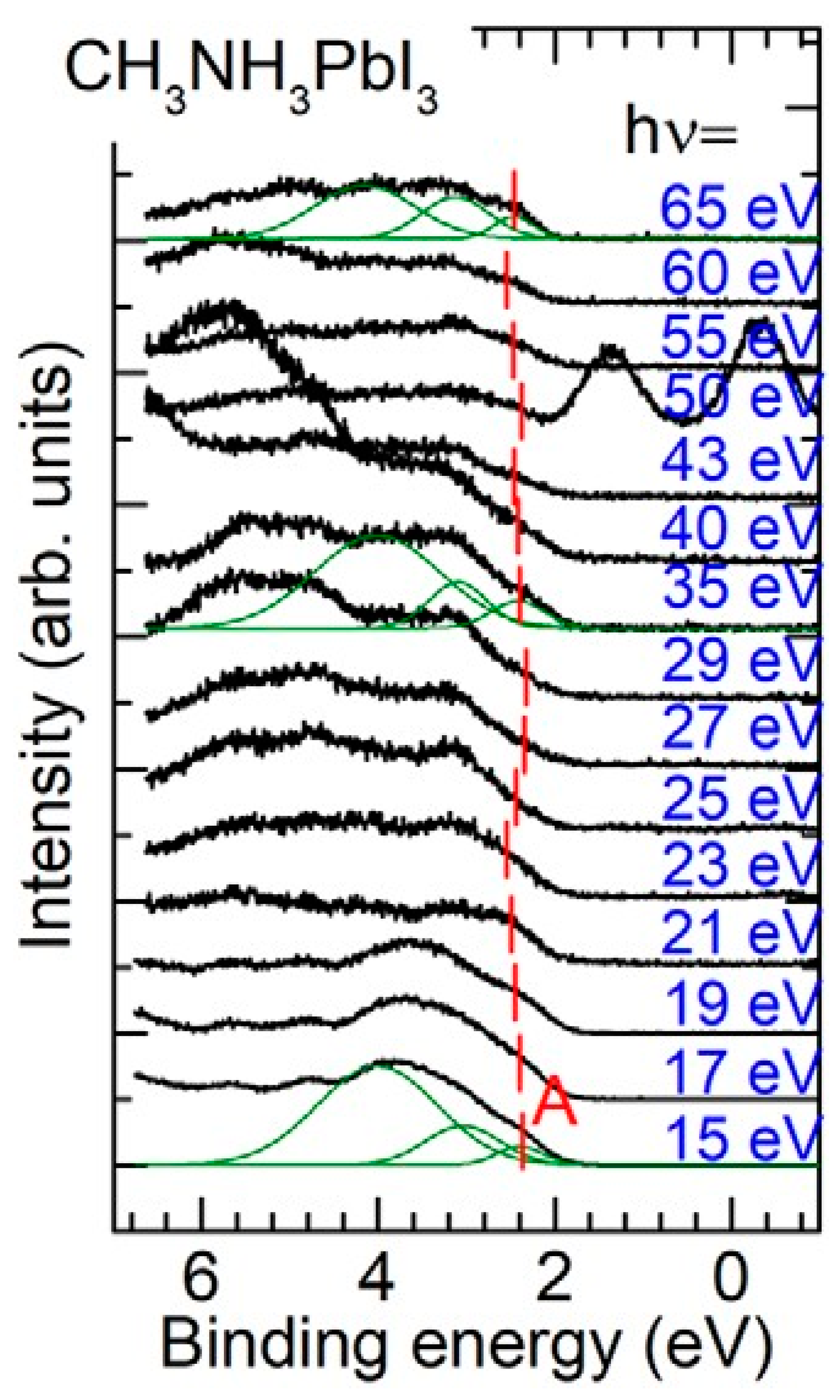
To learn more precisely the band structure, one must consider that the electron wave vector component perpendicular to the surface (k) is not conserved in ARPES experiments, as the emitted electrons experience a potential step V0 across the surface, as illustrated in Equation (2). ARPES measurements on MAPbI3 single crystal surface with synchrotron radiation have been performed to obtain V0 by measuring the momentum component k at different photon energies [120]. Figure 16 demonstrates the photon energy dependence of normal emission spectra for a cleaved MAPbI3 single crystal, wherein the binding energy is measured from the Fermi level and the photoemission intensities are normalized to the synchrotron ring current. The BE of top valence band peak is about 2.38 eV when is 15 eV. As the photon energy increases, the top valence band peak moves to the higher BE region, and shifts back at = 23 eV. The similar behavior of turning back of the top valence band peak is also seen from = 29 to 60 eV. The total shift of top valence band peak is about 0.2 eV, which is comparable with commonly observed for k dependence in organic thin films with the relaxation energy on hole caused by synchrotron radiation [8]. The energy band dispersion can explain the BE shift of the top valence band.
Figure 16 depicts two additional peaks above top valence band in the spectrum with = 50 eV, directly indicating the Auger electrons originated from I 4d. According to the band dispersion measurements perpendicular to the substrate with tuning photon energy, the surface normal components of the wave vector k of the photo-excited electron in the solid is given by Equation (6). By applying the assumptions of direct inter-band transitions, a free electron parabolic band in a constant V0, and free electron mass m0 for the final state [9], V0 from the dependence of the photoemission intensity can be calculated, as shown in Figure 17a [8,120].
In MAPbI3 single crystal, the nearly flat band in the region that is close to Γ point is confirmed from calculation [118], and the experiments as very small band dispersion [116]. It is expected that at Brillouin zone center (Γ point), and at boundaries, the density of states of parabolic final states have maxima, as shown in Figure 17a (right panel). Figure 17a (left panel) shows that the maxima of valence band intensities are seen at photon energies with ∼21 eV, ∼40 eV and ∼55 eV as shown, which are considered to come from the density of states at the final state, and is correspondent to the energies above the vacuum level of 13 eV, 33 eV and 48 eV, respectively. From these results, V0 is estimated to be −3 eV. In Figure 17b, a comparison can be seen between calculated top valence band dispersion curve along ΓX direction by calculations, using Vienna ab-initio simulation package (VASP), TB model and the experimental results plotted using Equation (6) with the inner potential V0 of −3 eV. By calculating the lattice constant a to be chosen as 6.25 Å, a good agreement can be achieved. This confirms that the surface structure of MAPbI3 single crystal at 300 K is dominated by a cubic phase, as indicated by the takeoff angle dependence of photoelectron spectra [116,120].

5. Final Remarks

In this article, we reviewed angle resolved photoemission studies on the electronic band structures of organic single crystals. It means to illustrate the band structure dependence on the structural properties of the organic materials, that is the key to the understanding of their characteristics. ARPES investigations have generated significant insight of the fundamental processes’ organic crystals. As in inorganic materials, the formation of electronic bands is mainly from the overlapping of the wavefunctions of the outermost electrons (valence electrons) of the atoms and molecules. However, in contrast to the strong s-p electron overlapping in most inorganic crystals, in organic conductors and semiconductors, the necessary overlapping is provided by the pi-conjugated electrons that depend strongly on the molecular packing, often resulting in highly anisotropic 1D band dispersions and providing evidence of interesting physical phenomena, such as spinons, holons, and polarons. In organo-metallic perovskite halides, on the other hand, again strong s-p orbitals from the metal and halide form the valence band, whose dispersion is similar to those in inorganic materials and possesses the 3D symmetry of perovskite. Many organic semiconductors show none-discernable dispersion, because the Van der Waals crystal nature and weak electron wavefunction overlap, as well as the strong electron-phonon coupling. One may expect that more systematic studies on the electronic band structures of organic crystals and more tools that probe the materials will be applied in the future, and a more complete picture of the electronic structure in organic crystals can be expected to emerge as a result.

Funding

The work is support in part by NSF DMR-1903962. B.E. acknowledges Hooker Dissertation Fellowship from the University of Rochester.

Conflicts of Interest

The authors declare no conflict of interest.

References

  1. Ashcroft, N.W.; Mermin, N.D. Solid State Physics; Harcourt: New York, NY, USA, 1976. [Google Scholar]
  2. Gao, Y. Surface analytical studies of interfaces in organic semiconductor devices. Mater. Sci. Eng. R Rep. 2010, 68, 39–87. [Google Scholar] [CrossRef]
  3. Gao, Y. Surface Analytical Studies of Interface Formation in Organic Light-Emitting Devices. Acc. Chem. Res. 1999, 32, 247–255. [Google Scholar] [CrossRef]
  4. Hwang, J.; Wan, A.; Kahn, A. Energetics of metal—Organic interfaces: New experiments and assessment of the field. Mater. Sci. Eng. R Rep. 2009, 64, 1–31. [Google Scholar] [CrossRef]
  5. Ishii, H.; Sugiyama, K.; Ito, E.; Seki, K. Energy level alignment and interfacial electronic structures at organic metal and organic organic interfaces. Adv. Mater. 1999, 11, 605–625. [Google Scholar] [CrossRef]
  6. Koch, N. Energy levels at interfaces between metals and conjugated organic molecules. J. Phys. Condens. Matter 2008, 20, 184008. [Google Scholar] [CrossRef]
  7. Salaneck, W.R.; Stafstrom, S.; Bredas, J.-L. Conjugated Polymer Surfaces and Interfaces; Cambridge University Press: New York, NY, USA, 1996. [Google Scholar]
  8. Ueno, N.; Kera, S. Electron spectroscopy of functional organic thin films: Deep insights into valence electronic structure in relation to charge transport property. Prog. Surf. Sci. 2008, 83, 490–557. [Google Scholar] [CrossRef]
  9. Hüfner, S.; Hüfner, P.D.S. Photoelectron Spectroscopy; Springer Science and Business Media LLC: Berlin, Germany, 2003. [Google Scholar]
  10. Einstein, A. On a Heuristic Viewpoint Concerning the Production and Transformation of Light. Ann. Phys. 1905, 17, 132–148. [Google Scholar] [CrossRef]
  11. Park, R.L.; Lagally, M.G. Solid State Physics: Surfaces; Academic Press: Cambridge, MA, USA, 1985. [Google Scholar]
  12. Reinert, F.; Hüfner, S. Photoemission spectroscopy—From early days to recent applications. New J. Phys. 2005, 7, 97. [Google Scholar] [CrossRef]
  13. Seah, M.; Seah, M.P.; Dench, W.A. Quantitative electron spectroscopy of surfaces: A standard data base for electron inelastic mean free paths in solids. Surf. Interface Anal. 1979, 1, 2. [Google Scholar] [CrossRef]
  14. Smith, K.E.; Kevan, S.D. The electronic structure of solids studied using angle resolved photoemission spectroscopy. Prog. Solid State Chem. 1991, 21, 49–131. [Google Scholar] [CrossRef]
  15. Damascelli, A.; Hussain, Z.; Shen, Z.-X. Angle-resolved photoemission studies of the cuprate superconductors. Rev. Mod. Phys. 2003, 75, 473–541. [Google Scholar] [CrossRef] [Green Version]
  16. Chiang, T.C.; Knapp, J.A.; Aono, M.; Eastman, D.E. Angle-resolved photoemission, valence band dispersions E(k), and electron and hole lifetimes for GaAs. Phys. Rev. B 1980, 21, 3513–3522. [Google Scholar] [CrossRef]
  17. Pope, M.; Swenberg, C.E. Electronic Processes in Organic Crystals and Polymers; Oxford University Press: New York, NY, USA, 1999. [Google Scholar]
  18. Hannewald, K.; Stojanović, V.M.; Schellekens, J.M.T.; Bobbert, P.A.; Kresse, G.; Hafner, J. Theory of polaron bandwidth narrowing in organic molecular crystals. Phys. Rev. B 2004, 69, 075211–075218. [Google Scholar] [CrossRef] [Green Version]
  19. Reddy, C.M.; Gundakaram, R.C.; Basavoju, S.; Kirchner, M.T.; Padmanabhan, K.A.; Desiraju, G.R. Structural basis for bending of organic crystals. Chem. Commun. 2005, 2005, 3945. [Google Scholar] [CrossRef]
  20. Arkhipov, S.G.; Losev, E.A.; Nguyen, T.T.; Rychkov, D.A.; Boldyreva, E. A large anisotropic plasticity of L-leucinium hydrogen maleate preserved at cryogenic temperatures. Acta Crystallogr. Sect. B Struct. Sci. Cryst. Eng. Mater. 2019, 75, 143–151. [Google Scholar] [CrossRef]
  21. Zhang, Y.; Yang, Z.; Zhang, S.; Zhou, X. Synthesis, Crystal Structure, and Solubility Analysis of a Famotidine Cocrystal. Crystal 2019, 9, 360. [Google Scholar] [CrossRef] [Green Version]
  22. Nicoud, L.; Licordari, F.; Myerson, A.S. Estimation of the Solubility of Metastable Polymorphs: A Critical Review. Cryst. Growth Des. 2018, 18, 7228–7237. [Google Scholar] [CrossRef]
  23. Mahon, J.K.; Zhou, T.X.S.R.; Forrest, S.R.; Schwambera, M.; Meyer, M. Organic VPD shows promise for OLED volume production (FPD). Solid State Technol. 2002, 45, 131–136. [Google Scholar]
  24. Andreasson, M.; Tengelin-Nilsson, M.; Ilver, L.; Kanski, J. Photoelectron spectroscopic studies of ultra-thin CuPc and PTCDA layers on Cu(100). Synth. Met. 2008, 158, 45–49. [Google Scholar] [CrossRef]
  25. Hasegawa, S.; Tanaka, S.; Yamashita, Y.; Inokuchi, H.; Fujimoto, H.; Kamiya, K.; Seki, K.; Ueno, N. Molecular orientation in thin films of bis(1,2,5-thiadiazolo)-p-quinobis(1,3-dithiole) on graphite studied by angle-resolved photoelectron spectroscopy. Phys. Rev. B 1993, 48, 2596–2600. [Google Scholar] [CrossRef]
  26. Hatch, R.C.; Höchst, H. Evolution of interface properties of the Pentacene/Bi(0001) system. Surf. Sci. 2010, 604, 1684–1687. [Google Scholar] [CrossRef]
  27. Huang, H.; Mao, H.; Chen, Q.; Yan, X.; Qian, H.; Zhang, J.; Li, H.; He, P.; Bao, S. The electronic states of ordered thin films of perylene on Ag(110). Phys. B Condens. Matter 2004, 352, 36–41. [Google Scholar]
  28. Huang, H.; Yan, X.; Mao, H.; Chen, Q.; Qian, H.; Zhang, J.; Li, H.; He, P.; Bao, S. The electronic states of ordered thin film of perylene on Ag(110). Acta Phys. Chim. Sin. 2004, 20, 892–896. [Google Scholar]
  29. Huang, J.; Kertesz, M. Electronic Structures and Charge Transport Properties of the Organic Semiconductor Bis[1,2,5]thiadiazolo-p-quinobis(1,3-dithiole), BTQBT, and Its Derivatives. J. Phys. Chem. B 2005, 109, 12891–12898. [Google Scholar] [CrossRef]
  30. Mao, H.Y.; Huang, H. The growth of perylene on Ru(0001). J. Chem. Phys. 2004, 121, 6972–6977. [Google Scholar]
  31. Chen, Q.; Mao, H.Y.; Huang, H.; Qian, H.Q.; Zhang, J.-H.; Li, H.Y.; He, P.-M.; Bao, S.-N.; Yan, X.-C. The structure and electronic state of the ordered thin film of perylene and tetracene on Ag(110) surface. Acta Phys. Sin. 2005, 54, 460–466. [Google Scholar]
  32. Nicoara, N.; Román, E.; Gómez-Rodríguez, J.; Martín-Gago, J.; Méndez, J. Scanning tunneling and photoemission spectroscopies at the PTCDA/Au(111) interface. Org. Electron. 2006, 7, 287–294. [Google Scholar] [CrossRef]
  33. Tengelin-Nilsson, M.; Ilver, L.; Kanski, J. Photoemission and low-energy electron diffraction studies of 3,4,9,10-perylene tetracarboxylic dianhydride layers on Si(111):H. Surf. Sci. 2000, 464, 265–271. [Google Scholar] [CrossRef]
  34. Tengelin-Nilsson, M.; Ilver, L.; Kanski, J. Photoelectron spectroscopic studies of thin PTCDA layers on TiSe2. Org. Electron. 2002, 3, 73–79. [Google Scholar] [CrossRef]
  35. Ueno, N. Angle-resolved UPS of ultrathin films of functional organic molecules with synchrotron radiation: Determination of molecular orientation by quantitative analysis of photoelectron angular distribution. J. Electron. Spectrosc. Relat. Phenom. 1996, 78, 345–350. [Google Scholar] [CrossRef]
  36. Ueno, N.; Kitamura, A.; Okudaira, K.K.; Miyamae, T.; Harada, Y.; Hasegawa, S.; Ishii, H.; Inokuchi, H.; Fujikawa, T.; Miyazaki, T.; et al. Angle-resolved ultraviolet photoelectron spectroscopy of thin films of bis(1,2,5-thiadiazolo)-p-quinobis (1,3-dithiole) on the MoS2 surface. J. Chem. Phys. 1997, 107, 2079–2088. [Google Scholar] [CrossRef]
  37. Vasseur, G.; Abadia, M.; Miccio, L.A.; Brede, J.; Garcia-Lekue, A.; de Oteyza, D.G.; Rogero, C.; Lobo-Checa, J.; Ortega, J.E. Pi Band Dispersion along Conjugated Organic Nanowires Synthesized on a Metal Oxide Semiconductor. J. Am. Chem. Soc. 2016, 138, 5685–5692. [Google Scholar] [CrossRef] [PubMed] [Green Version]
  38. Yue, W.; Han, H.; Hong-Ying, M.; Xin-Guo, Y.; Jian-Hua, Z.; Mang, W.; Shi-Ning, B. Study on the interface of an organic semiconductor grown on Ru(0001) surface. Acta Phys. Sin. 2004, 53, 1604–1610. [Google Scholar]
  39. Yamane, H.; Kanai, K.; Ouchi, Y.; Ueno, N.; Seki, K. Impact of interface geometric structure on organic–metal interface energetics and subsequent films electronic structure. J. Electron. Spectrosc. Relat. Phenom. 2009, 174, 28–34. [Google Scholar] [CrossRef]
  40. Yamane, H.; Kera, S.; Okudaira, K.K.; Yoshimura, D.; Seki, K.; Ueno, N. Intermolecular energy-band dispersion in PTCDA multilayers. Phys. Rev. B 2003, 68, 033102–033106. [Google Scholar] [CrossRef]
  41. Yamane, H.; Kosugi, N. Systematic study on intermolecular valence-band dispersion in molecular crystalline films. J. Electron. Spectrosc. Relat. Phenom. 2015, 204, 61–67. [Google Scholar] [CrossRef]
  42. Fan, Y.; Xinguo, Y.; Yue, W.; Jianhua, Z.; Jingzhi, S.; Mang, W.; Haiyang, L.; Pimo, H.; Shining, B. Study on the stages of N,N-dibutyl–3,4,9,10-perylene tetracarboxylic diimide growth on Ru (0001) surface. Phys. B Condens. Matter 2003, 334, 244–249. [Google Scholar] [CrossRef]
  43. Yang, J.-P.; Bussolotti, F.; Kera, S.; Ueno, N. Origin and role of gap states in organic semiconductor studied by UPS: As the nature of organic molecular crystals. J. Phys. D Appl. Phys. 2017, 50, 423002. [Google Scholar] [CrossRef]
  44. Stoumpos, C.C.; Cao, D.H.; Clark, D.J.; Young, J.; Rondinelli, J.M.; Jang, J.I.; Hupp, J.T.; Kanatzidis, M.G. Ruddlesden–Popper Hybrid Lead Iodide Perovskite 2D Homologous Semiconductors. Chem. Mater. 2016, 28, 2852–2867. [Google Scholar] [CrossRef]
  45. Landers, J.; Gor, G.Y.; Neimark, A.V. Density functional theory methods for characterization of porous materials. Colloids Surf. A Physicochem. Eng. Asp. 2013, 437, 3–32. [Google Scholar] [CrossRef]
  46. Berland, K.; Cooper, V.R.; Lee, K.; Schröder, E.; Thonhauser, T.; Hyldgaard, P.; Lundqvist, B. van der Waals forces in density functional theory: A review of the vdW-DF method. Rep. Prog. Phys. 2015, 78, 066501. [Google Scholar] [CrossRef] [PubMed] [Green Version]
  47. Kim, S.; Lee, J.K.; Kang, S.O.; Ko, J.; Yum, J.-H.; Fantacci, S.; De Angelis, F.; Di Censo, D.; Nazeeruddin, K.; Grätzel, M. Molecular Engineering of Organic Sensitizers for Solar Cell Applications. J. Am. Chem. Soc. 2006, 128, 16701–16707. [Google Scholar] [CrossRef] [PubMed]
  48. Ong, W.-J.; Tan, L.-L.; Ng, Y.H.; Yong, S.-T.; Chai, S.-P. Graphitic Carbon Nitride (g-C3N4)-Based Photocatalysts for Artificial Photosynthesis and Environmental Remediation: Are We a Step Closer to Achieving Sustainability? Chem. Rev. 2016, 116, 7159–7329. [Google Scholar] [CrossRef]
  49. Langreth, D.C.; Lundqvist, B.; Chakarova-Käck, S.D.; Cooper, V.R.; Dion, M.; Hyldgaard, P.; Kelkkanen, A.; Kleis, J.; Kong, L.; Li, S.; et al. A density functional for sparse matter. J. Phys. Condens. Matter 2009, 21, 084203. [Google Scholar] [CrossRef] [PubMed] [Green Version]
  50. Usta, H.; Facchetti, A.; Marks, T.J. n-Channel Semiconductor Materials Design for Organic Complementary Circuits. Acc. Chem. Res. 2011, 44, 501–510. [Google Scholar] [CrossRef] [PubMed]
  51. Mosconi, E.; Amat, A.; Nazeeruddin, M.; Grätzel, M.; De Angelis, F. First-Principles Modeling of Mixed Halide Organometal Perovskites for Photovoltaic Applications. J. Phys. Chem. C 2013, 117, 13902–13913. [Google Scholar] [CrossRef]
  52. Djurovich, P.I.; Mayo, E.I.; Forrest, S.R.; Thompson, M. Measurement of the lowest unoccupied molecular orbital energies of molecular organic semiconductors. Org. Electron. 2009, 10, 515–520. [Google Scholar] [CrossRef]
  53. Gao, J.; Miao, J.; Li, Z.; Teng, W.Y.; Yang, L.; Zhao, Y.; Liu, B.; Zhang, Q. A p-type Ti(iv)-based metal–organic framework with visible-light photo-response. Chem. Commun. 2014, 50, 3786–3788. [Google Scholar] [CrossRef]
  54. Dauth, M.; Wiessner, M.; Feyer, V.; Scholl, A.; Puschnig, P.; Reinert, F.; Kummel, S. Angle resolved photoemission from organic semiconductors: Orbital imaging beyond the molecular orbital interpretation. New J. Phys. 2014, 16, 103005. [Google Scholar] [CrossRef]
  55. Söderholm, S.; Girard, R.T.; Schweitzer, D. Electronic structure of the organic conductor α-(BEDT-TTF)2I3 sstudied by angle-resolvedand core-level photoelectron spectroscopy. Phys. Rev. B 1997, 55, 4267–4274. [Google Scholar] [CrossRef]
  56. Hennig, I.; Bender, K.; Schweitzer, D.; Dietz, K.; Endres, H.; Keller, H.J.; Gleitz, A.; Helberg, H.W. α And β-((BEDT-TTF)2+I3: Two Dimensional Organic Metals. Mol. Cryst. Liq. Cryst. 1985, 119, 337–341. [Google Scholar] [CrossRef]
  57. Yagubskii, E.B.; Shchegolev, I.F.; Laukhin, V.N.; Kononovich, P.A.; Karstovnik, M.V.; Zvarykina, A.V.; Buravov, L.I. Normal-pressure superconductivity in an organic metal (BEDT-TTF)2I3 [bis (ethylene dithiolo) tetrathiof ulvalene triiodide]. JETP Lett. 1984, 39, 12–16. [Google Scholar]
  58. Bender, K.; Hennig, I.; Schweitzer, D.; Dietz, K.; Endres, H.; Keller, H.J. Synthesis, Structure and Physical Properties of a Two-Dimensional Organic Metal, Di[bis(ethylenedithiolo)tetrathiofulvalene] triiodide, (BEDT-TTF)2+I3. Mol. Cryst. Liq. Cryst. 1984, 108, 359–371. [Google Scholar] [CrossRef] [Green Version]
  59. Zwick, F.; Onellion, M.; Voit, J.; Jérome, D.; Margaritondo, G.; Grioni, M. Band Mapping and Quasiparticle Suppression in the One-Dimensional Organic Conductor TTF-TCNQ. Phys. Rev. Lett. 1998, 81, 2974–2977. [Google Scholar] [CrossRef]
  60. Sing, M.; Schwingenschlögl, U.; Claessen, R.; Blaha, P.; Carmelo, J.; Martelo, L.M.; Sacramento, P.D.; Dressel, M.; Jacobsen, C.S. Electronic structure of the quasi-one-dimensional organic conductor TTF-TCNQ. Phys. Rev. B 2003, 68, 125111–125121. [Google Scholar] [CrossRef] [Green Version]
  61. Kistenmacher, T.J.; Phillips, T.E.; Cowan, D.O. The crystal structure of the 1:1 radical cation–radical anion salt of 2,2’-bis-l,3-dithiole (TTF) and 7,7,8,8-tetracyanoquinodimethane (TCNQ). Acta Crystallogr. Sect. B Struct. Crystallogr. Cryst. Chem. 1974, 30, 763–768. [Google Scholar] [CrossRef] [Green Version]
  62. Claessen, R.; Sing, M.; Schwingenschlögl, U.; Blaha, P.; Dressel, M.; Jacobsen, C.S. Spectroscopic Signatures of Spin-Charge Separation in the Quasi-One-Dimensional Organic Conductor TTF-TCNQ. Phys. Rev. Lett. 2002, 88, 096402. [Google Scholar] [CrossRef] [Green Version]
  63. Heeger, A.J.; Su, W.-P.; Kivelson, S.; Schrieffer, J.R. Solitons in conducting polymers. Rev. Mod. Phys. 1988, 60, 781–850. [Google Scholar] [CrossRef]
  64. Tang, C.W.; Vanslyke, S.A. Organic electroluminescent diodes. Appl. Phys. Lett. 1987, 51, 913–915. [Google Scholar] [CrossRef]
  65. Burroughes, J.H.; Bradley, D.D.C.; Brown, A.R.; Marks, R.N.; Mackay, K.; Friend, R.H.; Burn, P.L.; Holmes, A.B. Light-emitting diodes based on conjugated polymers. Nature 1990, 347, 539–541. [Google Scholar] [CrossRef]
  66. Podzorov, V.; Menard, E.; Borissov, A.; Kiryukhin, V.; Rogers, J.A.; Gershenson, M.E. Intrinsic Charge Transport on the Surface of Organic Semiconductors. Phys. Rev. Lett. 2004, 93, 086602. [Google Scholar] [CrossRef] [PubMed] [Green Version]
  67. Sundar, V.C.; Zaumseil, J.; Podzorov, V.; Menard, E.; Willett, R.L.; Someya, T.; Gershenson, M.E.; Rogers, J.A. Elastomeric Transistor Stamps: Reversible Probing of Charge Transport in Organic Crystals. Science 2004, 303, 1644–1646. [Google Scholar] [CrossRef] [PubMed] [Green Version]
  68. single crystal with angle-resolved photoemission. Appl. Phys. Lett. 2010, 96, 222106. [CrossRef]
  69. Kakuta, H.; Hirahara, T.; Matsuda, I.; Nagao, T.; Hasegawa, S.; Ueno, N.; Sakamoto, K. Electronic Structures of the Highest Occupied Molecular Orbital Bands of a Pentacene Ultrathin Film. Phys. Rev. Lett. 2007, 98, 247601. [Google Scholar] [CrossRef] [Green Version]
  70. Hummer, K.; Draxl, C. Electronic properties of oligoacenes from first principles. Phys. Rev. B 2005, 72, 205205. [Google Scholar] [CrossRef] [Green Version]
  71. Troisi, A. Prediction of the Absolute Charge Mobility of Molecular Semiconductors: The Case of Rubrene. Adv. Mater. 2007, 19, 2000–2004. [Google Scholar] [CrossRef]
  72. Li, Z.Q.; Podzorov, V.; Sai, N.; Martín, M.C.; Gershenson, M.E.; Di Ventra, M.; Basov, D.N. Light Quasiparticles Dominate Electronic Transport in Molecular Crystal Field-Effect Transistors. Phys. Rev. Lett. 2007, 99, 016403. [Google Scholar] [CrossRef] [Green Version]
  73. Silva-Filho, D.; Kim, E.-G.; Bredas, J.-L. Transport Properties in the Rubrene Crystal: Electronic Coupling and Vibrational Reorganization Energy. Adv. Mater. 2005, 17, 1072–1076. [Google Scholar] [CrossRef]
  74. Reese, C.; Bao, Z. High-Resolution Measurement of the Anisotropy of Charge Transport in Single Crystals. Adv. Mater. 2007, 19, 4535–4538. [Google Scholar] [CrossRef]
  75. Machida, S.; Nakayama, Y.; Duhm, S.; Xin, Q.; Funakoshi, A.; Ogawa, N.; Kera, S.; Ueno, N.; Ishii, H. Highest-Occupied-Molecular-Orbital Band Dispersion of Rubrene Single Crystals as Observed by Angle-Resolved Ultraviolet Photoelectron Spectroscopy. Phys. Rev. Lett. 2010, 104, 156401. [Google Scholar] [CrossRef]
  76. Nakayama, Y.; Uragami, Y.; Machida, S.; Koswattage, K.R.; Yoshimura, D.; Setoyama, H.; Okajima, T.; Mase, K.; Ishii, H. Full Picture of Valence Band Structure of Rubrene Single Crystals Probed by Angle-Resolved and Excitation-Energy-Dependent Photoelectron Spectroscopy. Appl. Phys. Express 2012, 5, 111601. [Google Scholar] [CrossRef]
  77. Vollmer, A.; Ovsyannikov, R.; Gorgoi, M.; Krause, S.; Oehzelt, M.; Lindblad, A.; Mårtensson, N.; Svensson, S.; Karlsson, P.; Lundvuist, M.; et al. Two dimensional band structure mapping of organic single crystals using the new generation electron energy analyzer ARTOF. J. Electron. Spectrosc. Relat. Phenom. 2012, 185, 55–60. [Google Scholar] [CrossRef] [Green Version]
  78. Koch, N.; Vollmer, A.; Salzmann, I.; Nickel, B.; Weiss, H.; Rabe, J.P. Evidence for Temperature-Dependent Electron Band Dispersion in Pentacene. Phys. Rev. Lett. 2006, 96, 156803. [Google Scholar] [CrossRef] [PubMed] [Green Version]
  79. Hasegawa, S.; Mori, T.; Imaeda, K.; Tanaka, S.; Yamashita, Y.; Inokuchi, H.; Fujimoto, H.; Seki, K.; Ueno, N. Intermolecular energy-band dispersion in oriented thin films of bis(1,2,5-thiadiazolo)-p-quinobis(1,3-dithiole) by angle-resolved photoemission. J. Chem. Phys. 1994, 100, 6969–6973. [Google Scholar] [CrossRef]
  80. Gavrila, G.; Mendez, H.; Kampen, T.; Zahn, D.R.; Vyalikh, D.V.; Braun, W. Energy band dispersion in well ordered N,N[sup ʹ]-dimethyl-3,4,9,10-perylenetetracarboxylic diimide films. Appl. Phys. Lett. 2004, 85, 4657. [Google Scholar] [CrossRef]
  81. Meier, H. Organic Semiconductors; Ebel, H.F., Ed.; Verlag Chemie: Winheim, Germany, 1974. [Google Scholar]
  82. Frohlich, H.; Sewell, G.L. Electric Conduction in Semiconductors. Proc. Phys. Soc. 1959, 74, 643–647. [Google Scholar] [CrossRef]
  83. Menard, E.; Marchenko, A.A.; Podzorov, V.; Gershenson, M.E.; Fichou, D.; Rogers, J.A. Nanoscale Surface Morphology and Rectifying Behavior of a Bulk Single-Crystal Organic Semiconductor. Adv. Mater. 2006, 18, 1552–1556. [Google Scholar] [CrossRef]
  84. Podzorov, V.; Pudalov, V.M.; Gershenson, M.E. Light-induced switching in back-gated organic transistors with built-in conduction channel. Appl. Phys. Lett. 2004, 85, 6039–6041. [Google Scholar] [CrossRef]
  85. Nakayama, Y.; Mizuno, Y.; Hikasa, M.; Yamamoto, M.; Matsunami, M.; Ideta, S.; Tanaka, K.; Ishii, H.; Ueno, N. Single-Crystal Pentacene Valence-Band Dispersion and Its Temperature Dependence. J. Phys. Chem. Lett. 2017, 8, 1259–1264. [Google Scholar] [CrossRef]
  86. Jurchescu, O.D.; Baas, J.; Palstra, T.T.M. Effect of impurities on the mobility of single crystal pentacene. Appl. Phys. Lett. 2004, 84, 3061. [Google Scholar] [CrossRef]
  87. Xin, Q.; Duhm, S.; Bussolotti, F.; Akaike, K.; Kubozono, Y.; Aoki, H.; Kosugi, T.; Kera, S.; Ueno, N. Accessing Surface Brillouin Zone and Band Structure of Picene Single Crystals. Phys. Rev. Lett. 2012, 108, 226401. [Google Scholar] [CrossRef] [PubMed] [Green Version]
  88. Yoshida, H.; Sato, N. Crystallographic and electronic structures of three different polymorphs of pentacene. Phys. Rev. B 2008, 77, 235205. [Google Scholar] [CrossRef]
  89. Vermeulen, D.; Zhu, L.; Goetz, K.P.; Hu, P.; Jiang, H.; Day, C.S.; Jurchescu, O.D.; Coropceanu, V.; Kloc, C.; McNeil, L. Charge Transport Properties of Perylene–TCNQ Crystals: The Effect of Stoichiometry. J. Phys. Chem. C 2014, 118, 24688–24696. [Google Scholar] [CrossRef]
  90. Pookpanratana, S.J.; Goetz, K.; Bittle, E.; Haneef, H.; You, L.; Hacker, C.A.; Robey, S.; Jurchescu, O.D.; Ovsyannikov, R.; Giangrisostomi, E. Electronic properties and structure of single crystal perylene. Org. Electron. 2018, 61, 157–163. [Google Scholar] [CrossRef] [PubMed]
  91. Fedorov, I.A.; Zhuravlev, Y.N.; Berveno, V.P. Structural and electronic properties of perylene from first principles calculations. J. Chem. Phys. 2013, 138, 94509. [Google Scholar] [CrossRef]
  92. Hodes, G. Perovskite-Based Solar Cells. Science 2013, 342, 317–318. [Google Scholar] [CrossRef]
  93. Lin, Q.; Armin, A.; Burn, P.L.; Meredith, P. Organohalide Perovskites for Solar Energy Conversion. Acc. Chem. Res. 2016, 49, 545–553. [Google Scholar] [CrossRef]
  94. Snaith, H.J. Perovskites: The Emergence of a New Era for Low-Cost, High-Efficiency Solar Cells. J. Phys. Chem. Lett. 2013, 4, 3623–3630. [Google Scholar] [CrossRef]
  95. Li, Z.; Yang, M.; Park, J.-S.; Wei, S.-H.; Berry, J.J.; Zhu, K. Stabilizing Perovskite Structures by Tuning Tolerance Factor: Formation of Formamidinium and Cesium Lead Iodide Solid-State Alloys. Chem. Mater. 2015, 28, 284–292. [Google Scholar] [CrossRef]
  96. Wang, J.; Neaton, J.B.; Zheng, H.; Nagarajan, V.; Ogale, S.B.; Liu, B.; Viehland, D.; Vaithyanathan, V.; Schlom, D.G.; Waghmare, U.V.; et al. Epitaxial BiFeO3 Multiferroic Thin Film Heterostructures. Science 2003, 299, 1719–1722. [Google Scholar] [CrossRef]
  97. Kojima, A.; Teshima, K.; Shirai, Y.; Miyasaka, T. Organometal Halide Perovskites as Visible-Light Sensitizers for Photovoltaic Cells. J. Am. Chem. Soc. 2009, 131, 6050–6051. [Google Scholar] [CrossRef] [PubMed]
  98. Jeon, N.J.; Na, H.; Jung, E.H.; Yang, T.-Y.; Lee, Y.G.; Kim, G.; Shin, H.-W.; Seok, S.I.; Lee, J.; Seo, J. A fluorene-terminated hole-transporting material for highly efficient and stable perovskite solar cells. Nat. Energy 2018, 3, 682–689. [Google Scholar] [CrossRef]
  99. Werner, J.; Weng, C.-H.; Walter, A.; Fesquet, L.; Seif, J.P.; De Wolf, S.; Niesen, B.; Ballif, C. Efficient Monolithic Perovskite/Silicon Tandem Solar Cell with Cell Area >1 cm2. J. Phys. Chem. Lett. 2015, 7, 161–166. [Google Scholar] [CrossRef] [PubMed]
  100. Rech, B.; Saliba, M.; Correa-Baena, J.-P.; Lang, F.; Kegelmann, L.; Mews, M.; Steier, L.; Abate, A.; Rappich, J.; Korte, L.; et al. Monolithic perovskite/silicon-heterojunction tandem solar cells processed at low temperature. Energy Environ. Sci. 2016, 9, 81–88. [Google Scholar]
  101. Wei, H.; Fang, Y.; Mulligan, P.L.; Chuirazzi, W.; Fang, H.-H.; Wang, C.; Ecker, B.; Gao, Y.; Loi, M.A.; Cao, L.; et al. Sensitive X-ray detectors made of methylammonium lead tribromide perovskite single crystals. Nat. Photon. 2016, 10, 333–339. [Google Scholar] [CrossRef]
  102. Tan, Z.-K.; Moghaddam, R.S.; Lai, M.L.; Docampo, P.; Higler, R.; Deschler, F.; Price, M.B.; Sadhanala, A.; Outón, L.M.P.; Credgington, D.; et al. Bright light-emitting diodes based on organometal halide perovskite. Nat. Nanotechnol. 2014, 9, 687–692. [Google Scholar] [CrossRef]
  103. Deschler, F.; Price, M.B.; Pathak, S.; Klintberg, L.E.; Jarausch, D.-D.; Higler, R.; Hüttner, S.; Leijtens, T.; Stranks, S.D.; Snaith, H.J.; et al. High Photoluminescence Efficiency and Optically Pumped Lasing in Solution-Processed Mixed Halide Perovskite Semiconductors. J. Phys. Chem. Lett. 2014, 5, 1421–1426. [Google Scholar] [CrossRef]
  104. Wang, C.; Ecker, B.; Wei, H.; Huang, J.; Meng, J.-Q.; Gao, Y. Valence band dispersion measurements of perovskite single crystals using angle-resolved photoemission spectroscopy. Phys. Chem. Chem. Phys. 2017, 19, 5361–5365. [Google Scholar] [CrossRef] [Green Version]
  105. Jishi, R.A.; Ta, O.B.; Sharif, A.A. Modeling of Lead Halide Perovskites for Photovoltaic Applications. J. Phys. Chem. C 2014, 118, 28344–28349. [Google Scholar] [CrossRef] [Green Version]
  106. Park, J.-S.; Choi, S.; Yan, Y.; Yang, Y.; Luther, J.; Wei, S.-H.; Parilla, P.; Zhu, K. Electronic Structure and Optical Properties of α-CH3NH3PbBr3 Perovskite Single Crystal. J. Phys. Chem. Lett. 2015, 6, 4304–4308. [Google Scholar] [CrossRef]
  107. Tian, W.; Zhao, C.; Leng, J.; Cui, R.; Jin, S. Visualizing Carrier Diffusion in Individual Single-Crystal Organolead Halide Perovskite Nanowires and Nanoplates. J. Am. Chem. Soc. 2015, 137, 12458–12461. [Google Scholar] [CrossRef] [PubMed]
  108. Saidaminov, M.I.; Abdelhady, A.L.; Murali, B.; Alarousu, E.; Burlakov, V.M.; Peng, W.; Dursun, I.; Wang, L.; He, Y.; Maculan, G.; et al. High-quality bulk hybrid perovskite single crystals within minutes by inverse temperature crystallization. Nat. Commun. 2015, 6, 7586. [Google Scholar] [CrossRef] [PubMed] [Green Version]
  109. Shi, D.; Adinolfi, V.; Comin, R.; Yuan, M.; Alarousu, E.; Buin, A.; Chen, Y.; Hoogland, S.; Rothenberger, A.; Katsiev, K.; et al. Low trap-state density and long carrier diffusion in organolead trihalide perovskite single crystals. Science 2015, 347, 519–522. [Google Scholar] [CrossRef] [PubMed] [Green Version]
  110. Niesner, D.; Wilhelm, M.; Levchuk, I.; Osvet, A.; Shrestha, S.; Brabec, C.J.; Fauster, T.; Batentschuk, M. Giant Rashba Splitting in CH3NH3PbBr3 Organic-Inorganic Perovskite. Phys. Rev. Lett. 2016, 117, 126401. [Google Scholar] [CrossRef] [Green Version]
  111. Etienne, T.; Mosconi, E.; De Angelis, F. Dynamical Origin of the Rashba Effect in Organohalide Lead Perovskites: A Key to Suppressed Carrier Recombination in Perovskite Solar Cells? J. Phys. Chem. Lett. 2016, 7, 1638–1645. [Google Scholar] [CrossRef]
  112. Amat, A.; Mosconi, E.; Ronca, E.; Quarti, C.; Umari, P.; Nazeeruddin, M.; Grätzel, M.; De Angelis, F. Cation-Induced Band-Gap Tuning in Organohalide Perovskites: Interplay of Spin–Orbit Coupling and Octahedra Tilting. Nano Lett. 2014, 14, 3608–3616. [Google Scholar] [CrossRef]
  113. Lee, M.-I.; Barragán, A.; Nair, M.N.; Jacques, V.L.R.; Le Bolloc’H, D.; Fertey, P.; Jemli, K.; Lédée, F.; Trippé-Allard, G.; Deleporte, E.; et al. First determination of the valence band dispersion of CH3NH3PbI3 hybrid organic–inorganic perovskite. J. Phys. D Appl. Phys. 2017, 50, 26LT02. [Google Scholar] [CrossRef]
  114. Zu, F.; Amsalem, P.; Egger, D.A.; Wang, R.; Wolff, C.M.; Fang, H.-H.; Loi, M.A.; Neher, D.; Kronik, L.; Duhm, S.; et al. Constructing the Electronic Structure of CH3NH3PbI3 and CH3NH3PbBr3 Perovskite Thin Films from Single-Crystal Band Structure Measurements. J. Phys. Chem. Lett. 2019, 10, 601–609. [Google Scholar] [CrossRef] [Green Version]
  115. Nandi, P.; Pandey, S.K.; Giri, C.; Singh, V.; Petaccia, L.; Manju, U.; Mahanti, S.D.B.; Topwal, D. Probing the Electronic Structure of Hybrid Perovskites in the Orientationally Disordered Cubic Phase. J. Phys. Chem. Lett. 2020, 11, 5719–5727. [Google Scholar] [CrossRef]
  116. Yang, J.-P.; Meissner, M.; Yamaguchi, T.; Zhang, X.-Y.; Ueba, T.; Cheng, L.; Ideta, S.; Tanaka, K.; Zeng, X.; Ueno, N.; et al. Band Dispersion and Hole Effective Mass of Methylammonium Lead Iodide Perovskite. Sol. RRL 2018, 2, 1800132. [Google Scholar] [CrossRef]
  117. Zhang, P.; Richard, P.; Qian, T.; Xu, Y.-M.; Dai, X.; Ding, H. A precise method for visualizing dispersive features in image plots. Rev. Sci. Instrum. 2011, 82, 43712. [Google Scholar] [CrossRef] [PubMed] [Green Version]
  118. Brivio, F.; Butler, K.T.; Walsh, A.; Van Schilfgaarde, M. Relativistic quasiparticle self-consistent electronic structure of hybrid halide perovskite photovoltaic absorbers. Phys. Rev. B 2014, 89, 155204. [Google Scholar] [CrossRef] [Green Version]
  119. Lindroos, M.; Sahrakorpi, S.; Bansil, A. Matrix element effects in angle-resolved photoemission from Bi2Sr2CaCu2O8: Energy and polarization dependencies, final state spectrum, spectral signatures of specific transitions, and related issues. Phys. Rev. B 2002, 65, 054514. [Google Scholar] [CrossRef] [Green Version]
  120. Yang, J.-P.; Ren, S.-X.; Yamaguchi, T.; Meissner, M.; Cheng, L.-W.; Zhou, L.; Ideta, S.-I.; Tanaka, K.; Kera, S. Valence band dispersion measured in the surface normal direction of CH3NH3PbI3 single crystals. Appl. Phys. Express 2019, 13, 011009. [Google Scholar] [CrossRef]
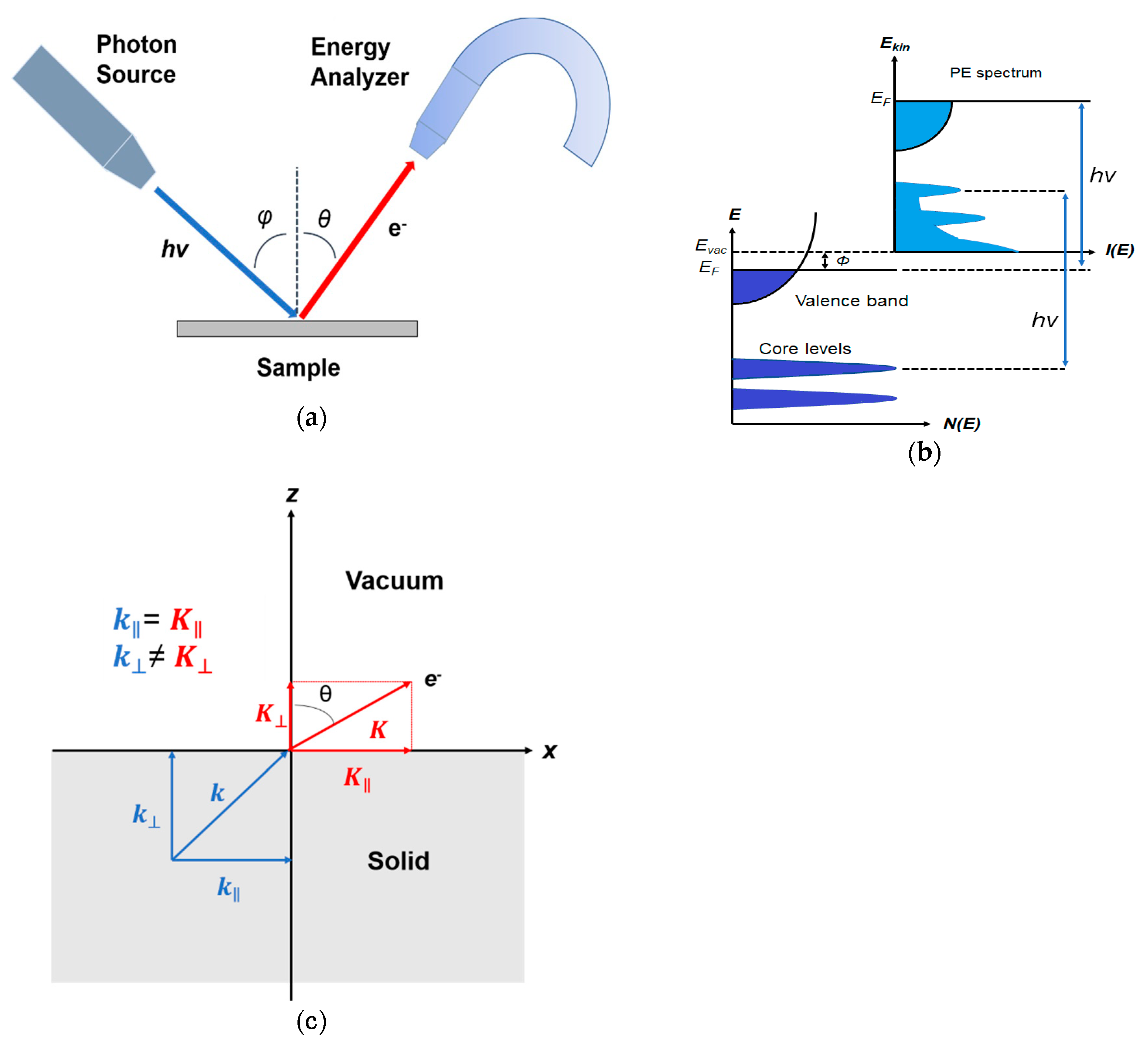
Figure 1. (a) Schematic of a photoemission experiment. The electrons are excited by the incident photons on the sample, then the excited electrons escape to the vacuum and are detected by an electron energy analyzer. (b) Schematic representation of photoemission spectroscopy (PES). The photoelectrons are excited from the occupied energy levels, including the valence bands as well as the core-level states. Additionally, secondary electrons excited by the photoelectrons that define the vacuum level cutoff are shown. (c) Photoemission geometry and relation of the electron wave vectors in vacuum ( K ) and in solid ( k ). Note that only the parallel momentum component is conserved.
Crystals 10 00773 g001
Figure 2. Angle-resolved photoemission spectroscopy (ARPES) photoemission spectra of α-(BEDT-TTF)2I3 obtained in normal emission, with photon energies between 21 and 150 eV. Different structures in the valence band regime are labeled A to H and marked with tick marks in the spectra. The spectra are normalized to the same height. From Ref. [55] with permission.
Crystals 10 00773 g002
Figure 3. Crystal structure of tetrathiafulvalene-tetracyanoquinodimethane (TTF-TCNQ). θF and θQ indicate the tilt angles of the planar TTF and TCNQ molecules, respectively, relative to the ac plane. Additionally shown is the monoclinic Brillouin zone with its high symmetry points. From Ref. [60] with permission.
Crystals 10 00773 g003
Figure 4. ARPES spectra of TTF-TCNQ measured along the ΓZ direction (hν =25 eV, T = 61 K). The thin lines are guides to the eye and are meant to indicate the dispersion of the spectral features. From Ref. [47] with permission.
Crystals 10 00773 g004
Figure 5. (a) Illustration of the lattice parameters within the a-b plane of rubrene single crystal. The molecular structure of rubrene is also shown in the inset. (b) The reciprocal lattice of crystalline rubrene. ΓX, ΓY and ΓM correspond to the a, b and the diagonal crystalline direction, respectively. From Ref. [68] with permission.
Crystals 10 00773 g005
Figure 6. Evolution of the highest occupied molecular orbital (HOMO) region in the rubrene ARPES spectra as a function of electron emission angle (θ) for single crystal rubrene along (a) ΓX, (b) ΓY, and (c) ΓM direction. The spectra are plotted in binding energy relative to the Fermi level. The boundaries of the 1st Brillouin Zone are noted by arrows. The inset shows the peak decomposition of the HOMO feature at Γ point. The evolution of the HOMO-B along ΓX direction is noted by short bars. From Ref. [68] with permission.
Crystals 10 00773 g006
Figure 7. Band dispersions of the two HOMO-derived bands of single crystal rubrene along (a) ΓX, (b) ΓY and (c) ΓM directions. The theoretical calculations from Ref. [61] are shown in the dashed lines. The solid curves are the dispersion obtained by analyzing the HOMO-B band using a simple tight-binding model. From Ref. [55] with permission.
Crystals 10 00773 g007
Figure 8. (a) Molecular structure of pentacene. (b) Schematic illustration of the molecular arrangement and unit cell of the pentacene (001) surface with the typical parallelogram-shape. (c) Surface Brillouin zone of pentacene single crystal. The direction of the ARPES measurements is indicated by the gray arrow. (d) ARPES spectra of pentacene single crystal taken toward the Γ−M′ direction at RT. The vertical bars are guides for the eyes to indicate the peak positions of spectral components. The measurement geometry is illustrated in the inset. From Ref. [85] with permission.
Crystals 10 00773 g008
Figure 9. (a) Pentacene ΓM ARPES spectral image taken at RT mapped on the E−K plane. The band calculation results [88] are also plotted as cross marks. (b) Binding energy positions of the three valence-band components derived through least-squares fitting of the ARPES spectra plotted as a function of the electron wavenumber parallel to the surface. The sizes of the symbols represent the intensities of the respective spectral components. The 1D-TB fitting curves for the first and second valence bands are shown as thick lines. From Ref. [85] with permission.
Crystals 10 00773 g009
Figure 10. (a) Chemical structure of perylene and (b) crystal structure of the α-perylene (hydrogen atoms have been omitted). In (c), schematic of laser-assisted photoemission measurements with crystal axes, excitation source (β) angle with respect to the sample surface normal and photoelectron emission angles θx and θy are identified for a bipolar coordinate system. From Ref. [90] with permission.
Crystals 10 00773 g010
Figure 11. Angle-resolved perylene HOMO using the angle resolved time of flight (ARTOF) spectrometer as a function of photoelectron emission angle in (a) θx and (b) θy. In (c), spectra integrated in θx and θy from (a,b) show the HOMO. Measurements were performed with a photon energy of 60 eV and cw laser at 473 nm. From Ref. [90] with permission.
Crystals 10 00773 g011
Figure 12. (a) MAPbBr3 single crystal with a surface area of 6 mm × 6 mm. (b) The reciprocal lattice of the cubic MAPbBr3. From Ref. [104] with permission.
Crystals 10 00773 g012
Figure 13. (a) Angle-resolved energy distribution curves of MAPbBr3 measured along ΓX; (b) Angle-resolved energy distributions curves of MAPbBr3 measured along ΓM. The four VB peaks are denoted by arrows and bars. The inset shows the detailed fitting of VB-C and VB-D peaks. From Ref. [104] with permission.
Crystals 10 00773 g013
Figure 14. Energy distribution curves (EDCs) of MAPbBr3 along ΓX and ΓM directions. The color represents the intensity of the photoemission spectrum. From Ref. [104] with permission.
Crystals 10 00773 g014
Figure 15. ARPES k-space 2D curvature band maps. Top row: MAPbBr3 single crystal along the (a) XM and (b) XR high-symmetry directions. Bottom row: MAPbI3 single crystal along the (d) XM and (e) XR high-symmetry directions. In all plots, corresponding DFT-calculated bands are shown with light blue lines (shifted in energy to match experimental band positions). A zoom into the topmost VB along the XR direction is given in (c) for MAPbBr3 and in (f) for MAPbI3. Fitting the VB edge regions with parabolic curves (green lines) yields a hole effective mass near R of ∼0.25 ± 0.05 m0 for MAPbBr3 and ∼0.50 ± 0.10 m0 for MAPbI3. From Ref. [114] with permission.
Crystals 10 00773 g015
Figure 16. (Color online) Photon energy dependence of angle-resolved photoemission spectroscopy with synchrotron radiation (SR-ARPES) spectra along the surface normal direction for cleaved MAPbI3 single crystal surface. The binding energy is referred to the Fermi level position. From Ref. [120] with permission.
Crystals 10 00773 g016
Figure 17. (Color online) (a) Determination of inner potential (V0) in MAPbI3 single crystal using photon energy dependence of ARPES intensity at θ = 0. The transition from a flat band to a parabolic final state gives intensity maxima at the critical points with peaked density-of-states. (b) The experimental dispersion for top valence band in the extended zone scheme and the best-fit curve (dash line) under both Vienna ab-initio simulation package (VASP) calculation and the approximation of TB model with considering V0 = −3 eV. From Ref. [120] with permission.
Crystals 10 00773 g017