Review

Polarization Volume Gratings for Near-Eye Displays and Novel Photonic Devices

College of Optics and Photonics, University of Central Florida, Orlando, FL 32816, USA
*
Author to whom correspondence should be addressed.
These authors contributed equally to this work.
Crystals 2020, 10(7), 561; https://doi.org/10.3390/cryst10070561
Submission received: 17 May 2020 / Revised: 5 June 2020 / Accepted: 24 June 2020 / Published: 1 July 2020
(This article belongs to the Special Issue Liquid-Crystal Polarization Gratings)

Abstract

:
Liquid crystal-based reflective polarization volume grating (PVG), also known as a linear Bragg–Berry phase optical element or a member of volume Bragg gratings (VBGs), is a functional planar structure with patterned orientation of optical axis. Due to the strong polarization selectivity, nearly 100% diffraction efficiency, large diffraction angle, and simple fabrication process, PVGs have found potential applications in novel photonic devices and emerging near-eye displays. In this review paper, we describe the operation principles, discuss the optical properties, present the fabrication methods, and provide promising applications of PVGs for near-eye displays and novel photonic devices.

1. Introduction

Polarization volume gratings (PVGs) based on patterned cholesteric liquid crystals (CLC) have attracted increasing attention in both liquid crystal and photonics fields [1,2,3]. Ascribed to its intriguing formation process and distinct optical properties, PVGs is particularly useful for novel optical devices and emerging displays, such as near-eye optical systems [4,5].
As a branch of Bragg gratings [6], PVGs with high efficiency, large diffraction angle, and strong polarization selectivity shed new light on a unique molecular orientation profile [2,7,8]. Following two-dimensional patterned alignment, the chiral molecules promote the self-organization of bulk LC and then an asymmetric helical structure is formed. Compared to conventional Bragg gratings, such as holographic volume gratings (HVGs) [9,10], PVGs achieve nearly 100% diffraction efficiency at a very large diffraction angle, moreover, it possesses a wider angular response to incident light. In addition to distinctive optical functions, PVGs also exhibit attractive features such as elasticity [11,12], thermal and electrical responses [13], etc. Besides its optical field, this CLC structure with the circularly polarized response is also surprisingly similar to the helical architecture of insects in nature, such as beetles [14]. In recent years after in-depth studies, a deeper understanding on the operation principles and characteristics of PVGs have been achieved [15]. Moreover, various PVG-based applications are emerging, such as beam steering, near-eye optical systems, head-up displays, and so on [16,17,18,19].
In this paper, we review recent advances of LC-based PVGs and propose some novel devices and systems based on this fascinating optical component. In Section 2, we begin with LC director configuration to reveal the operation principles of PVGs. In Section 3, we delve into the model and characterize the unique optical properties through simulation results. In Section 4, the fabrication process including molecular alignment method and exposure system is discussed. Finally, in Section 5, we introduce the applications of PVGs from two aspects: novel optical devices and emerging near-eye display systems, especially for augmented reality (AR). Besides reviewing the latest development, we also propose two PVG-based devices, photoluminescence enchantment film and polarization converter, and a multi-focal-plane system for waveguide-based AR displays.

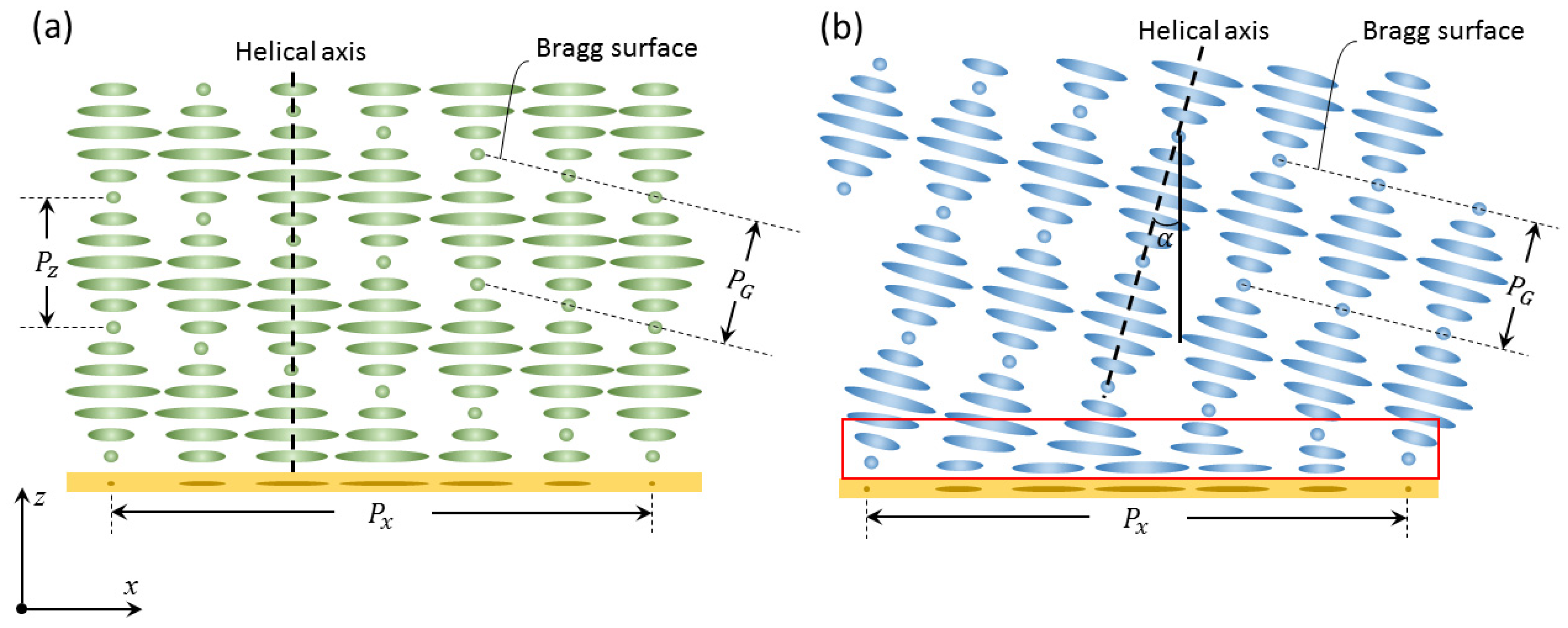
2. Operation Principles

Before we understand the physical principles, we need to know the internal structure of PVGs. Interestingly, with further research on physical models and experiments, the understanding of the LC director configuration in PVGs have experienced a transition. At first, the bulk structure was thought to be planar as Figure 1a depicts, where all the LC directors are parallel to the substrate [2,7,8]. The helical axis of CLC is perpendicular to the substrate and the CLC structure rotates following the bottom sinusoidal alignment pattern. This configuration produces an overall Bragg structure with Bragg pitch obeying the following equation:
1 P G 2 = 1 P x 2 + 1 P z 2 ,
where Pz in this case is equal to the CLC pitch PCLC. This presumed planar structure accords with our intuition in that all the LC directors follow the bottom planar alignment perfectly. Besides, like the geometric phase (or Pancharatnam–Berry phase) in transmissive LC polarization gratings [20,21,22,23], it also exists in reflective CLC structures. The rotation of the helical axis, therefore, generates the geometric phase that can be utilized to fabricate various optical elements [2]. So far, the planar structure explains some experimental results well.
Nonetheless, it has to be pointed out [15] that the bulk structure in planar-PVGs is not in the most relaxed state (pure helix structure), which is reflected in its free energy density (single-constant approximation):
f = K 2 [ ( n ^ ) 2 + ( n ^ × n ^ + 2 π P C L C ) 2 + | n ^ × × n ^ | 2 ] ,
f p l a n a r = K 2 ( 2 π P x ) 2 .
From Equation (3), the bulk free energy density of the planar structure is non-zero, and inversely proportional to (Px)2. The effect of the deviation from perfectly relaxed state is not obvious when Px is relatively large (much larger than the pitch of CLC) [2]. However, as the deflection angle of PVG gets larger, Px eventually evolves into a small value comparable to the CLC pitch length. In this case, the bulk free energy is so high that the system becomes unstable.
Recently, some experiments on the polarization response in PVG indicate that the bulk structure may be in a slanted configuration [24]. This issue is explicitly explained in [15] through simulation and experimental validation. The slanted PVG, as shown in Figure 1b, preserves the perfect helical structure in the bulk, which results in its lowest free energy (the bulk free energy is zero). The Bragg pitch PG in this case is equal to the CLC pitch PCLC. The bottom alignment gives the bulk helical structure a tilt angle α = arcsin(PG/PX) so as to match the bottom k-vector with the bulk periodic structure. To transit from the bottom planar alignment to the bulk slanted structure, there exists a transitional region (red box in Figure 1b) with non-zero free energy. However, the thickness of this transitional region is usually very small (tens of nanometers), so its contribution to the total free energy is minor. Therefore, the large-angle PVG formed by one-time spin coating or cell formation manifests the slanted structure.
As discussed in [15], the formation of planar-PVGs requires: 1) large Px (where planar-PVGs and slanted-PVGs are indistinguishable), or 2) strong anchoring and small thickness (less than 300 nm for each layer, and multiple spin-coatings to gain sufficient thickness, about 3 μm). At the same time, except polarization selectivity (which we will discuss later), the optical properties of planar-PVGs and slanted-PVGs are very similar in terms of reflection efficiency, wavelength response, and angular response. Therefore, from the perspective of practical application, the slanted-PVGs formed by one-time assembly are more advantageous. For the convenience of discussion, unless otherwise mentioned, the PVGs we refer to are the slanted ones.

3. Optical Properties

To comprehensively show the diffractive properties of PVGs, we have built a rigorous simulation model using the commercial Finite Element Method (FEM) package. For PVGs, there are several important characteristics that deserve special attention, including: diffraction efficiency, wavelength response, angular response, and polarization response. As shown in Figure 2a, only circularly polarized light with the same handedness as the helical rotation will be diffracted (in this case, right-handed circular polarization RCP), while the opposite handedness (LCP) will pass through. Besides, as Bragg volume gratings, the PVGs should be thick enough to establish Bragg diffraction. As depicted in Figure 2b, the diffraction efficiency is directly related to the film thickness.
As the thickness increases, diffraction efficiency grows monotonically at the beginning and then gradually saturates and approaches 100%. Therefore, for a certain wavelength, the required thickness for achieving high diffraction efficiency can be easily obtained based on the number of pitches. Compared to a conventional volume holographic grating, whose thickness is at least tens of micrometers, PVG (several micrometers) is much thinner. Besides, it is important to note that the efficiency is only for a circularly polarized input and the opposite circular polarization can fully transmit through the PVG. This feature provides high transmittance for the ambient light, which is important for see-through near-eye displays.

3.1. Wavelength Response

As analyzed in Section 2, the Bragg diffraction of PVGs is based on the helical twist along the LC optical axis. Therefore, the effective index modulation in PVGs is essentially the birefringence of the LC material. Due to the matured LCD industry, a wide range of birefringence (Δn = 0.05 to 0.4) is available. Same as the spectral properties of CLC, the reflection band of PVGs could be easily tuned by using a LC with different Δn, as Figure 3a depicts. Usually, as Δn increases, the reflection band grows wider. Furthermore, Figure 3b shows the diffraction efficiency spectra at three different diffraction angles with Δn of 0.15. From these simulation results, we can see that the diffraction efficiency and bandwidth are almost independent of diffraction angle. This means the PVGs can diffract light to different angles while keeping high efficiency, which is a very favorable feature for near-eye display systems.

3.2. Angular Response

It is not only diffraction spectra—the angular selectivity is also closely related to Δn. Thus, the angular response via different birefringence is investigated and illustrated in Figure 4a. The angular band of incident light becomes broader as Δn increases. Compared to the effective index modulation in holographic volume grating (typically of the order of 10−2), the LC birefringence is much higher (typically 0.15). As a result, the PVGs possesses wider angular bandwidth, which is much needed in many applications, such as light couplers in near-eye systems. These will be discussed later. Besides, it is worth mentioning that the angular response is sensitive to diffraction angle as well. Figure 4b shows the angular bandwidth for different diffraction angles with the same Δn (0.15). The trend is clear: as the diffraction angle increases, the angular band of incident light for achieving high diffraction efficiency is broader.

3.3. Polarization Response

In addition to spectral and angular responses of PVGs, polarization response is another unique property. This part is rarely discussed in previous reports, but the study of the polarization properties is necessary for PVGs to be used in cascaded optical systems where polarization control is pivotal. In an early study, it was described that the first order diffracted light maintains a circular polarization with an appropriate input circular polarization [7]. Specifically, the input circularly polarized light will keep its handedness or flip its handedness when diffracted by a reflective or transmissive PVGs. Later, Xiang et al. realized transmissive PVGs and surprisingly, the polarization state of the first order deviates severely from circular polarization [25], which was further proven in their simulation work [26]. Recently, Lee et al. analyzed the polarization response of reflective PVGs [24]. Numerical analysis shows that for the traditional planar configuration (Figure 1a), the polarization of the first order diffracted light deviates from circular polarization, which agrees with that reported in [26]. However, in experiment, the measured polarization state of the first order is highly circular (Stokes parameter S3 ~ 1). To explain this, the slanted configuration of PVG (Figure 1b) was proposed [24]. In a traditional planar PVG, the helical axis of cholesteric liquid crystals is oriented at the vertical axis, while in the slanted configuration, the helical axis is perpendicular to the Bragg planes.
To investigate the polarization property of the diffracted light, we use Stokes parameter S3 as an indicator. S3 denotes the degree of circular polarization of light. For example, S3 = 1 means right-handed circularly polarized light, while S3 = −1 stands for left-handed circularly polarized light. In the simulation, the horizontal period (Px) is 440 nm and vertical period (Pz) is 205 nm, which results in a slanted angle of α = 25°. The central wavelength is set at 532 nm, and Δn is 0.15. At normal incidence, the first-order polarization state of the slanted configuration is very close to circular polarization, as shown in Figure 5. By contrast, the diffracted light from the planar PVG significantly deviates from the circular polarization.
The previous investigation in polarization response seeded the finding of slanted configuration of PVGs. Nevertheless, the study of polarization response is merely a starting point. Both slant angle and incident angle make significant impacts on the polarization response. Further detailed analysis is necessary to understand its optical response.

4. Fabrication Process

In addition to unique optical characteristics, simple fabrication process is another noteworthy advantage of PVGs. Since PVGs are essentially a grating based on liquid crystal, recording high-quality patterns to align liquid crystal molecules is an important step during fabrication. Compared to conventional rubbing method [27], photo-alignment is a more advantageous option for generating precise patterns [28,29,30].

4.1. Liquid Crystal Alignment

Two approaches have been widely used in the fabrication based on photo-alignment materials. The first approach is surface alignment, which utilizes polarization interference to pattern a thin photo-alignment layer (PAL) [31,32,33,34,35]. The subsequently coated or sprayed liquid crystals self-align into gratings following the recorded patterned surface. To fabricate a polymeric PVG film, the LC precursor typically contains LC monomer, solvent, photo-initiator, and surfactant [36,37]. After the alignment process, we expose the sample with ultra-violet light (λ = 365 nm, room temperature, 10 mW/cm2 for 5 minutes) to polymerize the film. By contrast, to fabricate an electrically switchable PVG, two thin PAL-coated ITO glass substrates are assembled to form a uniform cell. After recording the alignment, we inject LC to the cell at an isotropic phase temperature [38], and let it cool down to room temperature. Then diffraction behavior of the PVG can be tuned by applying a voltage [14]. Surface alignment is the most established method so far for PVGs fabrication, as Figure 6a,b depict. The second approach is to record the volumetric polarization field by applying the photocycloaddition of cinnamate groups or similar all-in-one materials [39,40,41]. After the bulk LC alignment, the film is annealed to induce birefringence. This process is illustrated in Figure 6c.

4.2. Exposure System

The polarization field used to provide LC orientations is usually generated by light exposure [42,43,44]. In the simplest case, the grating can be formed by a polarization interferometer, as shown in Figure 7a. The linearly polarized laser beam is filtered and expanded, then split into two arms by a beam splitter (BS). A quarter-wave plate is placed in each arm to convert the incident light to RCP (Path 1) and LCP (Path 2). Then, these two beams are reflected by the mirrors (M) to interfere at the sample (S). Normally, the PVG phase can be obtained without other optical components in box A. However, appropriate modifications can be made to achieve exotic PVG phase profiles. For example, if a cylindrical lens is added, then the polarization filed has an additional parabolic phase in one dimension, so that the fabricated PVG shows a period of gradient change according to the direction of the cylindrical lens. In addition, if a lens is added, then the final PVG would have an additional parabolic phase profile in two dimensions, which makes it no longer a grating, but a polarization volume lens.
Besides, the polarized light field for fabricating PVGs can also come from a pixelated spatial light modulator (SLM) [45,46,47]. As depicted in Figure 7b, the collimated linearly polarized laser beam is converted to circular polarization by a QWP, and then is reflected by a high resolution SLM. The spatially modulated laser beam is changed back to linear polarization by the second QWP, and imaged onto the substrate coated with the photo alignment material. The resolution of this method is limited by the pixel density of the SLM. If the period is too small to record, then a lens-system needs to be added to compress the pattern to meet the requirements. Although this method has some limitations, it still provides a possible solution for fabricating PVGs and other PVG-based devices with designed patterns.

5. Emerging Applications

5.1. Novel Optical Devices

Due to the unique optical properties and simple fabrication process, in this section, we propose two PVG-based novel optical devices: photoluminescence enhancement film and polarization converter. Both theoretical analyses and simulation results will be fully discussed. Moreover, we present the potential of PVGs for continuous beam steering applications.

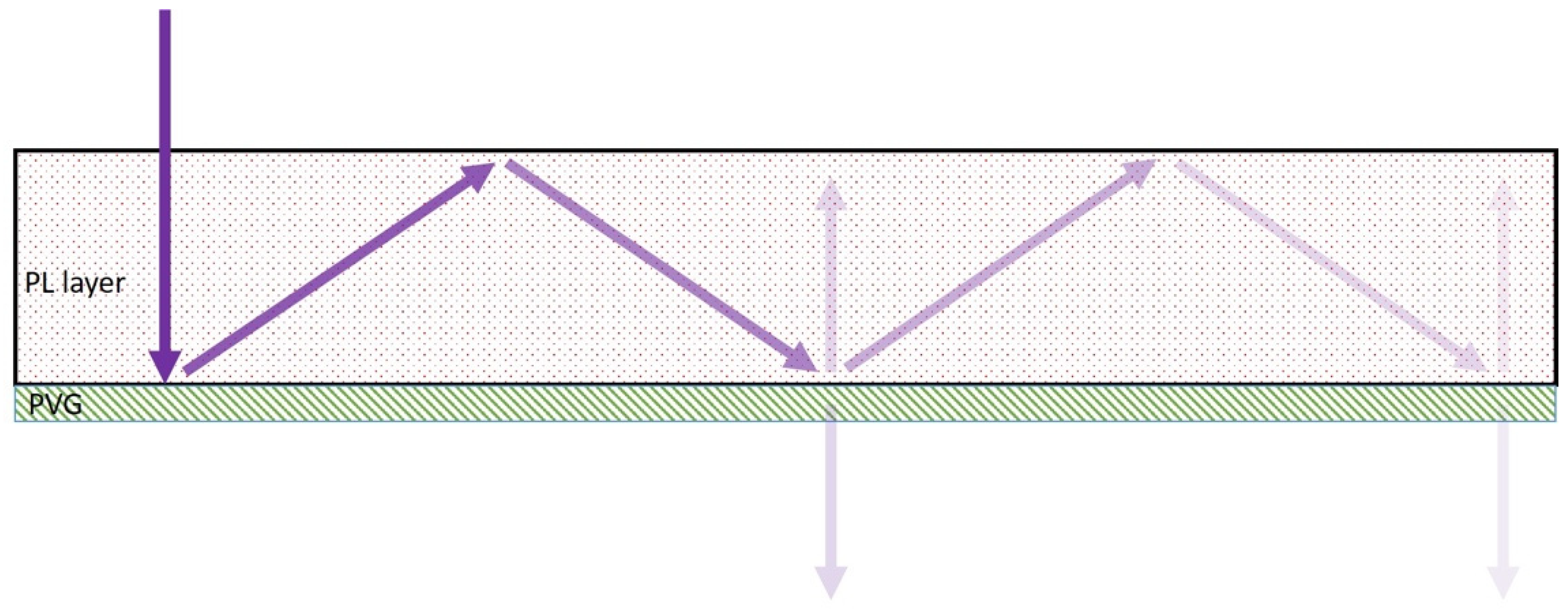
5.1.1. Photoluminescent Enhancement Film

Photoluminescent (PL) materials play important roles in many disciplines of the modern world, including but not limited to imaging, display, lighting, and even solar cells. The luminescent solar concentrators (LSCs), usually made of a down-converting PL layer in a geometric light guide, have attracted considerable attention due to their compact form factor, high flexibility, and cost efficiency for photovoltaics. The primary issue that slows the commercialization of LSCs is their relatively low light-collecting efficiency due to various losses in these devices. Here, we propose to employ PVGs to increase the photon collection rate in LSCs, especially those as alternatives to window glass, which require certain transparency.
The central concept is to deflect the input excitation light at an angle larger than the total internal reflection angle of the geometric light-guide. In doing so, the entire optical path length of the input excitation light in the down-converting materials can be significantly enhanced. The light loss due to insufficient absorption is therefore reduced, as illustrated in Figure 8. The geometric path length of the normally incident light after M total internal reflections can be expressed as:
L M = d ( 1 + 2 M cos θ ) ,
where d is the thickness of the PL layer and θ is the diffraction angle from the PVG. Although part of the excitation light is extracted from the light-guide during the second interaction with PVG, the geometrical optical path length is already significantly increased before this happens. For example, if the diffraction angle is around 60° for the excitation light, the effective path length is four times longer than the thickness of the PL. In other words, the optical density of the PL layer can be four times smaller while keeping the PL intensity unchanged under the same excitation circumstance. As a proof of concept, we fabricated a PVG with high efficiency at 350~400 nm for one polarization, whose zero-order transmittance is plotted in Figure 9a. Then, we attached on top of the PVG the PL layer, which is a polymeric film filled with perovskite quantum dot that emits green light under excitation [48]. Then the fabricated assembly was exposed to a UV flashlight for excitation. The area of the PL layer is larger than that of PVG, as marked by the red dashed lines in the photograph inside Figure 9b. The area with PVG (inside the red circle) appears brighter than the surrounding area. In addition to visual inspection, we also measured the brightness enhancement. The PL spectra with and without PVG were measured with a spectrometer (Ocean Optics spectrometer HR4000CG-UV-NIR, Ocean Optics, Inc., Florida, USA), and the results are plotted in Figure 9b, which prove that the PL intensity can be significantly enhanced with the proposed PL enhancement film. Here, the employed PVG only has one chiral layer and it diffracts RCP light. Thus, if a two-layer PVG that can diffract both RCP and LCP lights [7] is applied here, the PL intensity can be further enhanced. It is also noteworthy that PVGs working at deep blue or UV spectrum can manifest high transparency in the visible spectrum, as shown in the inset photo in Figure 9a. This merit enables another useful application for PL-based projection displays [49].

5.1.2. Polarization Converter

Thanks to their distinct polarization response and high diffraction efficiency, PVGs can also function as a polarization converter to convert an unpolarized light to a polarized light. In a high contrast LCD, a linearly polarized light is required. However, the most commonly used LED (light-emitting diode) backlight emits unpolarized light. Thus, instead of sacrificing half of the light using an absorptive polarizer, a polarization converter [50] can help make full use of the light from an unpolarized light source. Here, we provide the design of a novel thin-film polarization converter employing two PVGs and a c-plate, which is a homogeneous uniaxial layer with a c-axis perpendicular to its surface. The key feature of c-plate is that it generates phase retardation only for the oblique incident light, but not normal incidence. Figure 10 illustrates the design and working principle of the PVG-based polarization converter.
Firstly, the unpolarized light can pass through the designed R-PVG directly from oblique incidence because the Bragg condition is not satisfied. The c-plate does not alter the polarization state of light in the first pass. Then the L-PVG works as a polarizing beam splitter, diffracting one circular polarization (LCP) back to the c-plate and let the orthogonal one (RCP) pass through. The c-plate is designed to work at a large incident angle, therefore, the diffracted LCP light is converted to RCP after passing through it. It is feasible to tailor the periodicity of the two PVGs such that the light after its second passing through the c-plate (small incident angle while maintaining the polarization state) has an incident angle that satisfies the Bragg condition of the R-PVG. As a result, the outgoing light realizes the unification of polarization states by the polarization conversion. Compared to conventional polarization converters utilizing spatially pattern waveplates [51], our design necessitates neither spatial patterning nor certain space distance between adjacent optical components, manifesting easier fabrication process and thinner profile. It should be noted that the above-mentioned thin-film polarization converter has some limitations. Due to the limited spectral and angular bandwidth of PVGs and the phase retardation of the c-plate being dependent on the wavelength and incident angle, the convention efficiency may decrease if the incident wavelength and angle deviates from the designed configuration. To improve the angular response of the PVG, we can apply a multilayer structure or chirp method. However, the angular bandwidth of the c-plate should be kept relatively narrow and sharp so that it only responds to the light with a large incident angle. Thus, the proposed device is more promising for collimated narrow-band light sources with a small divergence. The efficiency of this device is highly dependent on the diffraction efficiency of each optical element. As discussed in Section 3, the diffraction efficiency of the PVGs can be higher than 95% when the thickness is enough to establish Bragg condition (~3µm).
Both reflective and transmissive PVGs can be utilized in the polarization conversion system. The transmissive PVG has a much longer period than the reflective one in the direction perpendicular to grating surface. It behaves like a Pancharatnam–Berry phase deflector [5] with a homogeneously and linearly twisted molecular structure in the axial direction [42]. The optical configuration of the transmissive-PVG polarization-converter is simpler than that based on the reflective one. With a sophisticated molecular orientation design, a transmissive PVG itself can convert an unpolarized incoming light into polarized beams and result in a larger beam divergence as the consequence. Figure 11 is a colored heat map showing the electric field intensity distribution inside a polarization-conversion transmissive PVG, where the orthogonal circular polarization components (RCP and LCP) are separated to illustrate the polarization evolution within the PVG. This electric field distribution is calculated with finite element method using COMSOL Multiphysics 5.2a (COMSOL Inc., Stockholm, Sweden). In this simulation, the thickness of transmissive PVG is 1.37 µm, and the grating period along and perpendicular to the grating surface is 0.78 µm and 3 µm, respectively. The extraordinary and ordinary refractive indices of the liquid crystal material at the incident wavelength (550 nm) are 1.70 and 1.50. Figure 11 clearly shows that both RCP and LCP input beams at normal incidence are converted to LCP in the output medium as the zero and first diffraction orders. The enlarged beam divergence issue can be resolved using fly’s eye array for better illumination uniformity in projector optics. This polarization converter can play a key role in enhancing the brightness of projection displays, such as the liquid-crystal-on-silicon light engines [52] for augmented reality.

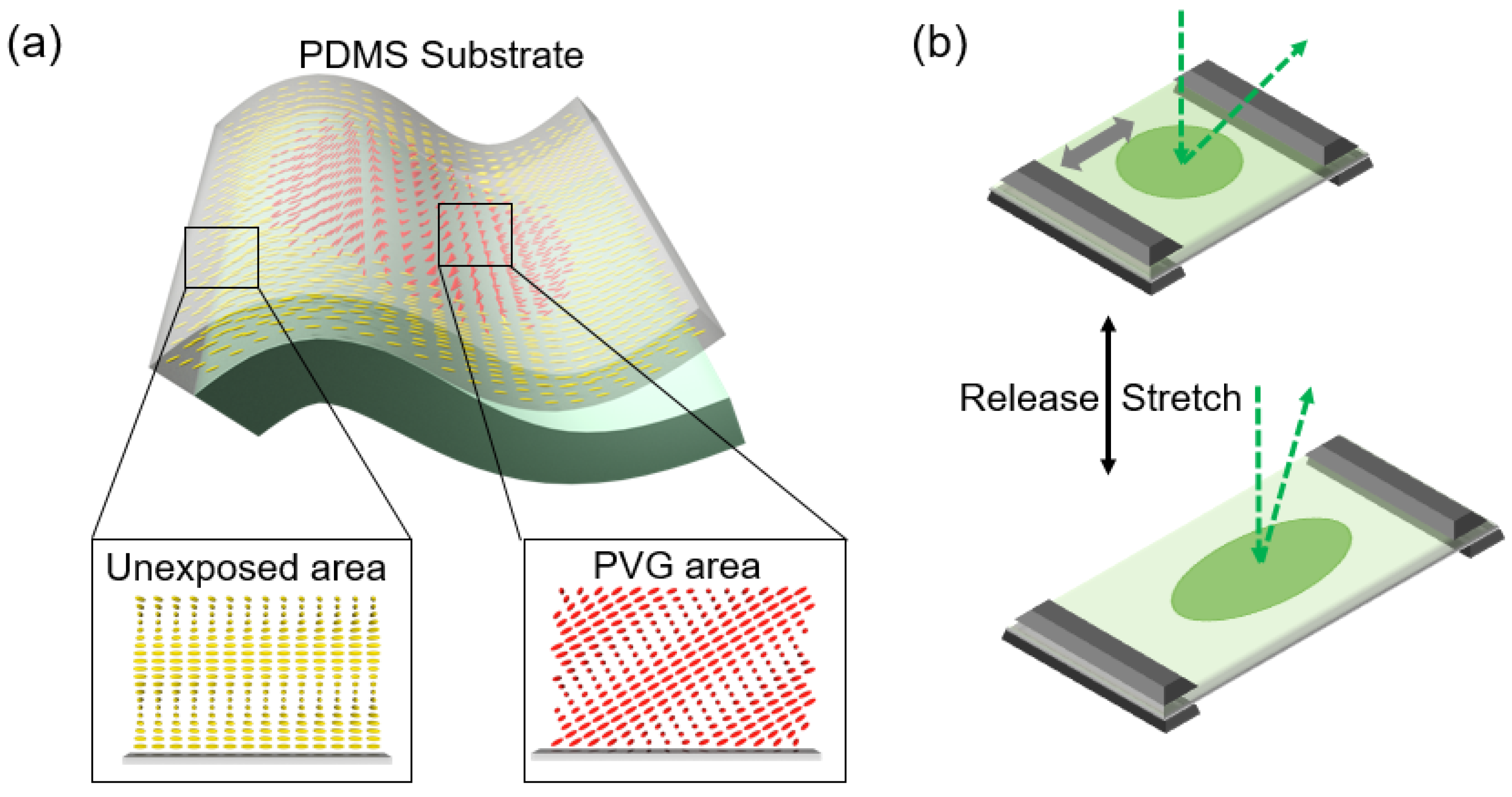
5.1.3. Beam Steering

As mentioned in Section 3, PVGs possess the ability to diffract the beam into different directions while keeping a large diffraction angle and high efficiency. Therefore, it is also a strong candidate for beam steering. Previously, volume gratings based on holographic polymer-dispersed liquid crystal (HPDLC) have been applied for steering light [53,54]. By stacking multiple holographic volume gratings together, discrete steering angles can be realized. However, due to the optical imperfections induced by the diffusion process, fabricating high-quality HPDLC based volume grating is still challenging. In contrast, high quality PVG structure is much easier to realize for active addressing and passive addressing beam steerers. In the former, liquid crystal is the switching medium, while in the latter, PVG is made of LC polymer and the switching medium is a LC-based polarization rotator [13]. In both active and passive devices, the switching time can be as fast as 1 ms, depending on the employed LC material and cell gap. For these devices, typically the field of view (angular response) at the central wavelength is around 17º. By applying multi-layer or gradient-pitch structure [8,18], both spectral and angular bandwidth can be dramatically widened while keeping a high diffraction efficiency.
Furthermore, by replacing the substrate from glass to PDMS (Figure 12a), a stretchable PVG film can be developed to realize continuous beam steering [11,12,17]. When the PVG film is stretched mechanically along the gray arrow in Figure 12b, the grating periodicity will continuously increase, and the corresponding diffraction angle will change accordingly. Releasing the strain will return the film to the initial state. By repeating the stretch-release cycle, the beam can be continuously steered inside the tuning range. It is worth mentioning that the diffraction angle of a PVG can reach more than 70º, but the actual steering range is not as large. For example, if the diffraction angle (at a given wavelength) is designed to be 55º, then the maximum reachable steering angle by stretching is about 43.5º, which means that the tuning range is 12º. The response time is dependent on the speed of the mechanical motor. Although the lifetime of this film has not been fully investigated, it provides a feasible solution for achieving continuous beam steering.

5.2. Near-Eye Displays

Besides novel optical elements, the unique properties of PVGs also open new space in near-eye displays, especially novel optical systems for augmented reality (AR) displays. At the current stage, there are still many unresolved challenges in near-eye display systems, such as expanding field of view (FOV), increasing the system efficiency, generating more depths to decrease the dazzling, and improving the uniformity of image [4,55,56]. The combination of PVGs and new optical systems offers intriguing solutions for near-eye displays [4].

5.2.1. Waveguide-Based AR Display Coupler

The basic construction of a waveguide-based AR display includes a display panel as image source, magnifying optics, and couplers to overlay computer generated images and real world. Normally, the light that comes from the display is first guided into a thin glass plate (the “waveguide”) by the input grating coupler, and then propagates inside the waveguide due to total internal reflection (TIR). An output coupler is placed at the see-through area to extract the light out of the waveguide and toward the human eye. As a critical component in this system, the grating coupler must meet the following conditions: large diffraction angle (to generate TIR), high single-order diffraction efficiency, and decent angular response (to support the required FOV). As we analyzed in Section 3, PVG meets these requirements and is therefore very suitable as coupler for waveguide-based AR displays.
Although both transmissive and reflective PVGs could be used as the input coupler, the reflective type shows a wider angular response bandwidth under the same average index [26]. Different from the input coupler, the output coupler has three important functions: 1) to export light from the waveguide to the human eye, 2) to achieve good uniformity of the outgoing light, and 3) to ensure an eye-box with decent size in both lateral and vertical directions. As a result, the output coupler with the pupil dilation function is usually called an exit pupil expander (EPE). A typical method for expanding the exit pupil is to use an output coupler with gradient diffraction efficiency. As the beam passes through the waveguide, its intensity decreases when it encounters the output coupler. This gradient-efficiency approach has been well developed in commercial AR products with holographic volume gratings or surface relief gratings [19]. Since the diffraction efficiency of PVGs is closely related to the thickness of the film, the gradient-efficiency can be achieved by controlling the thickness. Therefore, the gradient-efficiency method is also applicable to waveguides using PVG couplers, as Figure 13a illustrates [57,58].
Because the diffraction efficiency of PVGs is also highly sensitive to the input polarization state, another approach based on polarization management layer (PML) can also be utilized for expanding the exit light [4,19]. As Figure 13b shows, instead of generating gradient diffraction efficiency, a PML is added on the PVG-based waveguide to boost the efficiency and distribute the output light. In such a design, the PML is essentially a transparent LC film that has different azimuthal angles at different locations to control the polarization state. Each time the light passes through the PML, the polarization state is adjusted so that the required amount of light is coupled out during the next interaction with the output coupler. By designing the film thickness and the azimuthal angle of the LC in the PML, good uniformity of the output intensity along the entire out-coupling region can be achieved. Moreover, in comparison with the gradient-efficiency method, this PML approach can provide a relatively uniform ambient light transmittance, thereby avoiding clearly visible segment regions in the EPE area.

5.2.2. Wide Field of View

In most waveguide-based AR systems, the FOV is highly dependent on the angular response of the coupler and is limited by the TIR of the waveguide itself. In order to expand the FOV of the system, we can tackle two aspects: (1) using a high index glass to extend the TIR limit, and (2) increasing the angular response of the couplers. To broaden the angular response, some designs based on the vertical twist structures [59,60] have been developed for both reflective and transmissive PVGs. Previously, a two-layer twisted transmissive PVG was designed, in which each layer is a transmissive PVG with the same deflection angle but different slanted angles. This method is effective but the diffraction efficiency is not as high as expected. As reported in [59], the measured angular bandwidth is 40º and the average diffraction efficiency within the band is about 30%. More recently, for reflective PVGs, a gradient-pitch method [60] was proposed and fabricated to dramatically widen the angular bandwidth [61]. By inducing a gradually changing period along the vertical direction while the period along the horizontal direction is fixed, a wider angular bandwidth can be obtained. Figure 14a shows the device structure of this gradient-pitch PVG. The fabrication procedure of such a gradient-pitch grating is similar to that described in Section 4, except for different precursors and UV curing conditions. Compared to previous mixture (LC monomers, solvents, photo-initiators, and surfactants), we added a 1.50-wt% UV dye (Avobenzone) to help generate a gradually changing period, and then raised the curing temperature to 60 °C and cured with a low power ultraviolet light (λ = 365 nm, 0.3 mW/cm2) for 40 minutes. Figure 14b shows the simulated and measured angular responses and a photo of the sample. In the experiment, the angular bandwidth was extended to 54° while keeping a diffraction efficiency over 80%. Such a wide FOV enables PVGs to become strong contenders for AR displays [18].

5.2.3. Polarization Volume Lens (PVL)

As couplers with high efficiency and large deflection angle, PVGs have shown promising applications in AR optical systems. However, for certain situations, such as multi-focal plane designs, they require components with more features than regular gratings—for example, a lens. Fortunately, it is possible to further implement the lens function on the basis of PVGs. As discussed in Section 4.2, if a lens is added into the exposure setting as a template, then the final PVG would have an additional parabolic phase profile, which makes it a polarization volume lens (PVL) [2]. The operation principle of PVL is equivalent to combining a reflective PVG with a lens. Such a PVL is useful as an off-axis mirror for converging or diverging the incident light; the incident light is focused/diversified by the lens profile and diffracted by the grating. Recently, a PVL with a small f-number and large diffraction angle has been reported [62] that provides a solid theoretical foundation and a promising fabrication process. Figure 15a illustrates the schematic diagram of the PVL.
Next, let us go back to the AR system. Due to the limited focal planes, one of the major challenges for near-eye displays is the vergence-accommodation conflict (VAC) [63,64]. To overcome the VAC issue, several methods have been proposed, such as multi-focal-plane displays [51,65], light field displays [66,67], and holographic displays [68,69]. Here, we propose a two-focal-plane system with PVL for waveguide-based AR displays. Figure 15b depicts the system configuration. This design has a stacked two-layer structure, which has been widely used in commercial products. The light beams carrying different polarization information (LCP and RCP) are respectively coupled into different two-layer waveguides through two counter-twist PVGs. Due to the TIR, the light propagates inside the glass slab and reaches the output areas. Here, two PVLs with opposite polarization responses (LCP and RCP) and different diopters are used as output couplers to extract light toward the human eye. Based on this simple but effective design, the image contents with different polarization states are projected to different depths.

6. Conclusions

In conclusion, we have reviewed some recent advances in the physical principles and fabrication methods of liquid crystal-based polarization volume gratings and their applications for novel optical devices and emerging near-eye displays. Based on the theoretical and experimental results, we proposed two PVG-based novel devices aiming for different applications, such as photoluminescence enhancement film and polarization convertor. Moreover, both the PML-PVG combination system and the two-focal-plane system using PVL enable promising applications of PVG-based devices for near-eye displays. With the latest development of liquid crystal materials and optical systems, PVGs have rapidly evolved from a single-function grating to a multi-functional device. Due to the unique and attractive optical properties, PVGs have been successfully applied in novel optical systems to satisfy the increasing demands from both basic researches and practical applications, such as near-eye displays for augmented reality. We believe that the continuing and substantial progress, as well as the emergence of novel materials and hybridization approaches, will promote the development of not only PVG, but also next-generation displays to benefit human life.

Author Contributions

Methodology, K.Y. and T.Z.; writing—original draft preparation, K.Y., T.Z., Z.H. and J.X.; writing—review and editing, K.Y. and S.-T.W.; supervision, S.-T.W. All authors have read and agreed to the published version of the manuscript.

Funding

Air Force Office of Scientific Research (Grant No. FA9550-14-1-0279) and GoerTek Electronics.

Conflicts of Interest

The authors declare no conflict of interest.

References

  1. Barboza, R.; Bortolozzo, U.; Clerc, M.G.; Residori, S. Berry phase of light under bragg reflection by chiral liquid-crystal media. Phys. Rev. Lett. 2016, 117, 053903. [Google Scholar] [CrossRef] [Green Version]
  2. Kobashi, J.; Yoshida, H.; Ozaki, M. Planar optics with patterned chiral liquid crystals. Nat. Photonics 2016, 10, 389. [Google Scholar] [CrossRef]
  3. Kobashi, J.; Mohri, Y.; Yoshida, H.; Ozaki, M. Circularly-polarized, large-angle reflective deflectors based on periodically patterned cholesteric liquid crystals. Opt. Data Process. Storage 2017, 3, 61–66. [Google Scholar] [CrossRef]
  4. Lee, Y.H.; Zhan, T.; Wu, S.T. Prospects and challenges in augmented reality displays. Virtual Real. Intell. Hardw. 2019, 1, 10–20. [Google Scholar] [CrossRef]
  5. Zhan, T.; Lee, Y.H.; Tan, G.; Xiong, J.; Yin, K.; Gou, F.; Zou, J.; Zhang, N.; Zhao, D.; Yang, J.; et al. Pancharatnam-Berry optical elements for head-up and near-eye displays. J. Opt. Soc. Am. B 2019, 36, D52–D65. [Google Scholar] [CrossRef]
  6. Gaylord, T.K.; Moharam, M.G. Thin and thick gratings: Terminology clarification. Appl. Opt. 1981, 20, 3271–3273. [Google Scholar] [CrossRef] [PubMed]
  7. Weng, Y.; Xu, D.; Zhang, Y.; Li, X.; Wu, S.T. Polarization volume grating with high efficiency and large diffraction angle. Opt. Express 2016, 24, 17746–17759. [Google Scholar] [CrossRef] [PubMed]
  8. Lee, Y.H.; Yin, K.; Wu, S.T. Reflective polarization volume gratings for high efficiency waveguide-coupling augmented reality displays. Opt. Express 2017, 25, 27008–27014. [Google Scholar] [CrossRef]
  9. Rasmussen, T. Overview of high-efficiency transmission gratings for molecular spectroscopy. Spectroscopy 2014, 29, 32–39. [Google Scholar]
  10. Moharam, M.G.; Grann, E.B.; Pommet, D.A.; Gaylord, T.K. Formulation for stable and efficient implementation of the rigorous coupled-wave analysis of binary gratings. J. Opt. Soc. Am. A 1995, 12, 1068–1076. [Google Scholar] [CrossRef]
  11. Yin, K.; Lee, Y.H.; He, Z.; Wu, S.T. Stretchable, flexible, and adherable polarization volume grating film for waveguide-based augmented reality displays. J. Soc. Inf. Disp. 2019, 27, 232–237. [Google Scholar] [CrossRef]
  12. Yin, K.; Lee, Y.H.; He, Z.; Wu, S.T. Stretchable, flexible, rollable, and adherable polarization volume grating film. Opt. Express 2019, 27, 5814–5823. [Google Scholar] [CrossRef] [PubMed]
  13. Chen, R.; Lee, Y.H.; Zhan, T.; Yin, K.; An, Z.; Wu, S.T. Multistimuli-responsive self-organized liquid crystal Bragg gratings. Adv. Opt. Mater. 2019, 7, 1900101. [Google Scholar] [CrossRef]
  14. McDonald, L.T.; Finlayson, E.D.; Wilts, B.D.; Vukusic, P. Circularly polarized reflection from the scarab beetle Chalcothea smaragdina: Light scattering by a dual photonic structure. Interface Focus 2017, 7, 20160129. [Google Scholar] [CrossRef]
  15. Xiong, J.; Chen, R.; Wu, S.T. Device simulation of liquid crystal polarization gratings. Opt. Express 2019, 27, 18102–18112. [Google Scholar] [CrossRef] [Green Version]
  16. Zhan, T.; Lee, Y.H.; Xiong, J.; Tan, G.; Yin, K.; Yang, J.; Liu, S.; Wu, S.T. High-efficiency switchable optical elements for advanced head-up displays. J. Soc. Inf. Disp. 2019, 27, 223–231. [Google Scholar] [CrossRef]
  17. He, Z.; Gou, F.; Chen, R.; Yin, K.; Zhan, T.; Wu, S.T. Liquid Crystal Beam Steering Devices: Principles, Recent Advances, and Future Developments. Crystals 2019, 9, 292. [Google Scholar] [CrossRef] [Green Version]
  18. Yin, K.; Lin, H.Y.; Wu, S.T. Chirped polarization volume grating for wide FOV and high efficiency waveguide-based AR displays. J. Soc. Inf. Disp. 2020, 28, 368–374. [Google Scholar] [CrossRef]
  19. Lee, Y.H.; Tan, G.; Yin, K.; Zhan, T.; Wu, S.T. Compact see-through near-eye display with depth adaption. J. Soc. Inf. Disp. 2018, 26, 64–70. [Google Scholar] [CrossRef]
  20. Tabiryan, N.V.; Serak, S.V.; Roberts, D.E.; Steeves, D.M.; Kimball, B.R. Thin waveplate lenses of switchable focal length-new generation in optics. Opt. Express 2015, 23, 25783–25794. [Google Scholar] [CrossRef]
  21. McManamon, P.F.; Bos, P.J.; Escuti, M.J.; Heikenfeld, J.; Serati, S.; Xie, H.; Watson, E.A. A review of phased array steering for narrow-band electrooptical systems. Proc. IEEE 2009, 97, 1078–1096. [Google Scholar] [CrossRef]
  22. Lee, Y.H.; Tan, G.; Zhan, T.; Weng, Y.; Liu, G.; Gou, F.; Peng, F.; Tabiryan, N.V.; Gauza, S.; Wu, S.T. Recent progress in Pancharatnam-Berry phase optical elements and the applications for virtual/augmented realities. Opt. Data Process. Storage 2017, 3, 79–88. [Google Scholar] [CrossRef]
  23. Sarkissian, H.; Park, B.; Tabirian, N.; Zeldovich, B. Periodically aligned liquid crystal: potential application for projection displays. Mol. Cryst. Liq. Cryst. 2006, 451, 1–19. [Google Scholar] [CrossRef] [Green Version]
  24. Lee, Y.H.; He, Z.; Wu, S.T. Optical properties of reflective liquid crystal polarization volume gratings. J. Opt. Soc. Am. B 2019, 36, D9–D12. [Google Scholar] [CrossRef]
  25. Xiang, X.; Kim, J.; Komanduri, R.; Escuti, M.J. Nanoscale liquid crystal polymer Bragg polarization gratings. Opt. Express 2017, 25, 19298–19308. [Google Scholar] [CrossRef]
  26. Xiang, X.; Escuti, M.J. Numerical analysis of Bragg polarization gratings. J. Opt. Soc. Am. B 2019, 36, D1–D8. [Google Scholar] [CrossRef]
  27. Berreman, D.W. Solid surface shape and the alignment of an adjacent nematic liquid crystal. Phys. Rev. Lett. 1972, 28, 1683–1686. [Google Scholar] [CrossRef]
  28. Gibbons, W.M.; Shannon, P.J.; Sun, S.T.; Swetlin, B.J. Surface-mediated alignment of nematic liquid crystals with polarized laser light. Nature 1991, 351, 49–50. [Google Scholar] [CrossRef]
  29. Schadt, M.; Schmitt, K.; Kozinkov, V.; Chigrinov, V. Surface-Induced Parallel Alignment of Liquid Crystals by Linearly Polymerized Photopolymers. Jpn. J. Appl. Phys. 1992, 31, 2155–2164. [Google Scholar] [CrossRef]
  30. Ichimura, K. Photoalignment of liquid-crystal systems. Chem. Rev. 2000, 100, 1847–1874. [Google Scholar] [CrossRef]
  31. Chigrinov, V.; Muravski, A.; Kwok, H.S.; Takada, H.; Akiyama, H.; Takatsu, H. Anchoring properties of photoaligned azo-dye materials. Phys. Rev. E 2003, 68, 061702. [Google Scholar] [CrossRef] [Green Version]
  32. Tseng, M.C.; Yaroshchuk, O.; Bidna, T.; Srivastava, A.K.; Chigrinov, V.; Kwok, H.S. Strengthening of liquid crystal photoalignment on azo dye films: Passivation by reactive mesogens. RSC Adv. 2016, 6, 48181–48188. [Google Scholar] [CrossRef]
  33. Wang, J.; McGinty, C.; Reich, R.; Finnemeyer, V.; Clark, H.; Berry, S.; Bos, P. Process for a reactive monomer alignment layer for liquid crystals formed on an azodye sublayer. Materials 2018, 11, 1195. [Google Scholar] [CrossRef] [Green Version]
  34. Wang, J.; McGinty, C.; West, J.; Bryant, D.; Finnemeyer, V.; Reich, R.; Berry, S.; Clark, H.; Yaroshchuk, O.; Bos, P. Effects of humidity and surface on photoalignment of brilliant yellow. Liq. Cryst. 2017, 44, 863–872. [Google Scholar] [CrossRef]
  35. Ouskova, E.; Vergara, R.; Hwang, J.; Roberts, D.; Steeves, D.M.; Kimball, B.R.; Tabiryan, N. Dual-function reversible/irreversible photoalignment material. J. Mol. Liq. 2018, 267, 205–211. [Google Scholar] [CrossRef]
  36. Decker, C.; Moussa, K. Real-time kinetic study of laser-induced polymerization. Macromolecules 1989, 22, 4455–4462. [Google Scholar] [CrossRef]
  37. Bryant, S.J.; Nuttelman, C.R.; Anseth, K.S. Cytocompatibility of UV and visible light photoinitiating systems on cultured NIH/3T3 fibroblasts in vitro. J. Biomater. Sci. Polym. Ed. 2000, 11, 439–457. [Google Scholar] [CrossRef]
  38. Yang, D.K.; Wu, S.T. Fundamentals of Liquid Crystal Devices, 2nd ed.; John Wiley & Sons: Chichester, UK, 2014. [Google Scholar]
  39. Sakhno, O.; Gritsai, Y.; Sahm, H.; Stumpe, J. Fabrication and performance of efficient thin circular polarization gratings with Bragg properties using bulk photo-alignment of a liquid crystalline polymer. Appl. Phys. B 2018, 124, 52. [Google Scholar] [CrossRef]
  40. Emoto, A.; Matsumoto, T.; Yamashita, A.; Shioda, T.; Ono, H.; Kawatsuki, N. Large birefringence and polarization holographic gratings formed in photocross-linkable polymer liquid crystals comprising bistolane mesogenic side groups. J. Appl. Phys. 2009, 106, 073505. [Google Scholar] [CrossRef]
  41. Ono, H.; Emoto, A.; Takahashi, F.; Kawatsuki, N.; Hasegawa, T. Highly stable polarization gratings in photocrosslinkable polymer liquid crystals. J. Appl. Phys. 2003, 94, 1298–1303. [Google Scholar] [CrossRef]
  42. Gao, K.; McGinty, C.; Payson, H.; Berry, S.; Vornehm, J.; Finnemeyer, V.; Roberts, B.; Bos, P. High-efficiency large-angle Pancharatnam phase deflector based on dual-twist design. Opt. Express 2017, 25, 6283–6293. [Google Scholar] [CrossRef]
  43. Kakichashvili, S.D. Method for phase polarization recording of holograms. Sov. J. Quantum Electron. 1974, 4, 795–798. [Google Scholar] [CrossRef]
  44. Crawford, G.P.; Eakin, J.N.; Radcliffe, M.D.; Callan-Jones, A.; Pelcovits, R.A. Liquid-crystal diffraction gratings using polarization holography alignment techniques. J. Appl. Phys. 2005, 98, 123102. [Google Scholar] [CrossRef] [Green Version]
  45. Chen, P.; Wei, B.Y.; Hu, W.; Lu, Y.Q. Liquid-Crystal-Mediated Geometric Phase: From Transmissive to Broadband Reflective Planar Optics. Adv. Mater. 2019, 31, 1903665. [Google Scholar] [CrossRef]
  46. De Sio, L.; Roberts, D.E.; Liao, Z.; Nersisyan, S.; Uskova, O.; Wickboldt, L.; Tabiryan, N.; Steeves, D.M.; Kimball, B.R. Digital polarization holography advancing geometrical phase optics. Opt. Express 2016, 24, 18297–18306. [Google Scholar] [CrossRef]
  47. Wu, H.; Hu, W.; Hu, H.C.; Lin, X.W.; Zhu, G.; Choi, J.W.; Chigrinov, V.; Lu, Y.Q. Arbitrary photo-patterning in liquid crystal alignments using DMD based lithography system. Opt. Express 2012, 20, 16684–16689. [Google Scholar] [CrossRef] [Green Version]
  48. He, J.; He, Z.; Towers, A.; Zhan, T.; Chen, H.; Zhou, L.; Zhang, C.; Chen, R.; Sun, T.; Gesquiere, A.J.; et al. Ligand assisted swelling–deswelling microencapsulation (LASDM) for stable, color tunable perovskite–polymer composites. Nanoscale Adv. 2020, 2, 2034–2043. [Google Scholar] [CrossRef]
  49. Cheng, B.; Sun, L.; Yu, G.; Sun, T.X. A novel emissive projection display (EPD) on transparent phosphor screen. Proc. SPIE 2017, 10117. [Google Scholar] [CrossRef]
  50. Kim, J.; Komanduri, R.K.; Lawler, K.F.; Kekas, D.J.; Escuti, M.J. Efficient and monolithic polarization conversion system based on a polarization grating. Appl. Opt. 2020, 51, 4852–4857. [Google Scholar] [CrossRef] [Green Version]
  51. Du, T.; Fan, F.; Tam, A.M.W.; Sun, J.; Chigrinov, V.G.; Kwok, H.S. Complex nanoscale-ordered liquid crystal polymer film for high transmittance holographic polarizer. Adv. Mater. 2015, 27, 7191–7195. [Google Scholar] [CrossRef]
  52. Zhan, T.; Zou, J.; Lu, M.; Chen, E.; Wu, S.T. Wavelength-multiplexed multi-focal-plane seethrough near-eye displays. Opt. Express 2019, 27, 27507–27513. [Google Scholar] [CrossRef] [PubMed]
  53. Sutherland, R.L.; Natarajan, L.V.; Tondiglia, V.P.; Bunning, T.J. Bragg gratings in an acrylate polymer consisting of periodic polymer-dispersed liquid-crystal planes. Chem. Mater. 1993, 5, 1533–1538. [Google Scholar] [CrossRef]
  54. Liu, Y.J.; Sun, X.W. Holographic polymer-dispersed liquid crystals materials, formation, and applications. Adv. Optoelectron. 2008, 2008, 684349. [Google Scholar] [CrossRef] [Green Version]
  55. Cakmakci, O.; Rolland, J. Head-worn displays: A review. J. Disp. Tech. 2006, 2, 199–216. [Google Scholar] [CrossRef]
  56. Wang, J.; Liang, Y.; Xu, M. Design of a see-through head-mounted display with a freeform surface. JOSK 2015, 19, 614–618. [Google Scholar] [CrossRef] [Green Version]
  57. Saarikko, P. Diffractive exit-pupil expander with a large field of view. Proc. SPIE 2008, 7001. [Google Scholar] [CrossRef]
  58. Äyräs, P.; Saarikko, P.; Levola, T. Exit pupil expander with a large field of view based on diffractive optics. J. Soc. Inf. Disp. 2009, 17, 659–664. [Google Scholar] [CrossRef]
  59. Xiang, X.; Kim, J.; Escuti, M.J. Bragg polarization gratings for wide angular bandwidth and high efficiency at steep deflection angles. Sci. Rep. 2018, 8, 7202. [Google Scholar] [CrossRef] [Green Version]
  60. Broer, D.J.; Lub, J.; Mol, G.N. Wide-band reflective polarizers from cholesteric polymer networks with a pitch gradient. Nature 1995, 378, 467–469. [Google Scholar] [CrossRef]
  61. Yin, K.; Lin, H.Y.; Wu, S.T. Chirped polarization volume grating with ultra-wide angular bandwidth and high efficiency for see-through near-eye displays. Opt. Express 2019, 27, 35895–35902. [Google Scholar] [CrossRef]
  62. Yin, K.; He, Z.; Wu, S.T. Reflective polarization volume lens with small f-number and large diffraction angle. Adv. Opt. Mater. 2020, 8, 2000170. [Google Scholar] [CrossRef]
  63. Hoffman, D.M.; Girshick, A.R.; Akeley, K.; Banks, M.S. Vergence-accommodation conflicts hinder visual performance and cause visual fatigue. J. Vis. 2008, 8, 33. [Google Scholar] [CrossRef] [PubMed]
  64. Hua, H. Enabling focus cues in head-mounted displays. Proc. IEEE 2017, 105, 805–824. [Google Scholar] [CrossRef]
  65. He, Z.; Yin, K.; Wu, S.T. Passive polymer-dispersed liquid crystal enabled multi-focal plane displays. Opt. Express 2020, 28, 15294–15299. [Google Scholar] [CrossRef]
  66. Arimoto, H.; Javidi, B. Integral 3D imaging with digital reconstruction. Opt. Lett. 2001, 26, 157–159. [Google Scholar] [CrossRef] [PubMed]
  67. Huang, F.C.; Chen, K.; Wetzstein, G. The light field stereoscope: Immersive computer graphics via factored near-eye light field displays with focus cues. ACM Trans. Graph. 2015, 34, 60. [Google Scholar] [CrossRef]
  68. Wakunami, K.; Hsieh, P.Y.; Oi, R.; Senoh, T.; Sasaki, H.; Ichihashi, Y.; Okui, M.; Huang, Y.P.; Yamamoto, K. Projection-type see-through holographic three-dimensional display. Nat. Commun. 2016, 7, 12954. [Google Scholar] [CrossRef] [Green Version]
  69. Li, G.; Lee, D.; Jeong, Y.; Cho, J.; Lee, B. Holographic display for see-through augmented reality using mirror-lens holographic optical element. Opt. Lett. 2016, 41, 2486–2489. [Google Scholar] [CrossRef]
Figure 1. Different LC director configurations of PVG. (a) Planar-PVG with helical axis perpendicular to substrate surface. (b) Slanted-PVG with helical axis perpendicular to Bragg surface. The red box indicates the transitional region from planar to slanted structure.
Crystals 10 00561 g001
Figure 2. (a) Schematic of the beam diffracted by a PVG. (b) Simulated diffraction efficiency as a function of film thickness. The diffraction efficiency is defined as the ratio of first-order diffracted light to incident light at a specific diffraction angle and center wavelength. The horizontal period is 440 nm, vertical period is 205 nm, Δn = 0.15, the diffraction angle is 50°, and the central wavelength is 532 nm. The efficiency is higher than 95% when the thickness exceeds 3 µm.
Crystals 10 00561 g002
Figure 3. Wavelength response of PVGs. The horizontal period (Px) is 440 nm, vertical period (Pz) is 205 nm, and the central wavelength is 532 nm. (a) Diffraction efficiency spectra at normal incidence and 50° diffraction angle with different refractive index contrast and (b) different diffraction angles with Δn = 0.15.
Crystals 10 00561 g003
Figure 4. Angular response of PVGs. The horizontal period (Px) is 440 nm, vertical period (Pz) is 205 nm, and the central wavelength is 532 nm. (a) Diffraction efficiency versus incident angle at three refractive index contrasts with 50° diffraction angle and (b) three diffraction angles with Δn = 0.15.
Crystals 10 00561 g004
Figure 5. Stokes parameters S3 as a function of film thickness. The horizontal period (Px) is 440 nm, vertical period (Pz) is 205 nm, central wavelength is 532 nm and Δn is 0.15.
Crystals 10 00561 g005
Figure 6. Fabrication procedures of PVGs. (a) Surface alignment for LC polymeric PVG. (b) Electrically responsive LC PVG. (c) Volume alignment.
Crystals 10 00561 g006
Figure 7. Exposure setups of PVGs. (a) Two-beams interferometer. (b) Exposure based on SLM.
Crystals 10 00561 g007
Figure 8. Schematic illustration of a photoluminescent enhancement film based on PVGs.
Crystals 10 00561 g008
Figure 9. (a) Transmittance spectrum of a PVG as the luminance enhancement film. (b) Measured PL intensity of a perovskite film with and without the PVG.
Crystals 10 00561 g009
Figure 10. Schematic illustration of a thin-film polarization converter based on two PVGs and a c-plate.
Crystals 10 00561 g010
Figure 11. Electric field distribution in a polarization converting transmissive PVG. Scale bar indicates the electric field distribution. Tilt originates from the diffraction of the transmissive PVG.
Crystals 10 00561 g011
Figure 12. (a) Schematic illustration of stretchable PVG film. (b) Schematic diagram of mechanically controlled PVG film for continuous beam steering.
Crystals 10 00561 g012
Figure 13. Schematic illustration of waveguide-based optical systems. (a) Using gradient-efficiency output coupler. (b) Using uniform-efficiency output coupler with a PML.
Crystals 10 00561 g013
Figure 14. (a) Schematic diagram of gradient-pitch PVG. (b) Simulation and experimental results of angular response. Inset: photo of the sample.
Crystals 10 00561 g014
Figure 15. (a) Schematic diagram of PVL, (b) Schematic illustration of two-focal-plane waveguide-based AR system.
Crystals 10 00561 g015

