1. Introduction
Investment casting is the primary method for manufacturing aircraft turbine parts from nickel and cobalt superalloys because it can be used to fabricate products with intricate geometries [
1,
2,
3,
4,
5].
The key advantages of investment casting lie in its ability to obtain superior dimensional accuracy, smooth surfaces, and intricately shaped shell molds [
6,
7]. Manufacturing investment shell molds with good mechanical properties strongly depends on the quality and technological properties of the shell molds [
8,
9,
10]. During investment casting, multilayer ceramic molds are used to reconstruct intricate geometrical shapes. Such molds should have appropriate physical and mechanical properties because they influence the quality of the fabricated castings [
11,
12,
13]. The most important properties are the porosity, high gas permeability during metal pouring, and mechanical strength [
14,
15,
16]. The structures of ceramic shell molds may have from one to several dozen layers. The number of layers determines the characteristic properties of the molds when used to fabricate monocrystalline castings.
There are three types of layers formed in a foundry:
First layer (prime coat): this layer mainly helps maintain surface roughness tolerance, even at minimum mold layer oxidation. It also helps obtain the desired dimensional and structural tolerance and shape accuracy of the mold. The prime coat must not interact with liquid metal and must precisely coat the wax pattern without short-run castings, air bubbles, cracks, or slivers after drying.
Second layer (sealing coat): reinforces the prime coat.
Structural layers (back-up coats): provide the desired strength, porosity, and gas permeability to ceramic shell molds [
17,
18,
19,
20].
The basic materials used to fabricate shell molds are alumina, ZrSiO
4, quartz, and aluminosilicate (e.g., mullite), and are typically applied as small grain-size powders, or meals [
21,
22,
23].
The most commonly used binders are those containing nano silica [
24,
25,
26]. Previously, alcohol binders based on hydrolyzed ethyl silicate were widely used; however, due to environmental concerns and health issues, binders with alcohol thinners were replaced with water-thinning binders [
27]. To improve the rheological properties of slurries and the physical and mechanical properties of ceramic shell molds, several other additives have been used, e.g., fluxes and wetting and defoaming agents [
9,
28,
29,
30,
31,
32,
33,
34].
One of the most recent solutions in investment casting is the use of silicon carbide (SiC) as the mold base material and a water-based structural binder with Al
2O
3 instead of SiO
2 nanoparticles. This provides the individual mold layers with the desired mechanical strength. Binders containing colloidal SiO
2 cannot always be used to fabricate SiC-based shell molds because SiO
2 acts as a decomposition catalyst for SiC at high temperatures, which can significantly decrease the thermal conductivity of ceramic slurries. The broader application of water-based binders with colloidal Al
2O
3 is inhibited by their low commercial availability and higher price compared with binders with SiO
2 nanoparticles [
35].
In contrast to the powders commonly used to fabricate shell molds on an industrial scale, SiC has a high thermal resistance and stability, high electrical conductivity, and thermal shock resistance [
35,
36,
37]. Its broad availability, relatively low price, and desirable physical and chemical properties make it widely used in various industries, e.g., construction, materials engineering, electronics, aerospace, and motor industries [
14,
35]. The conductivity of SiC (130 W/m·K) at 20 °C is particularly interesting for modern investment casting and aviation. Due to its high thermal conductivity, the use of SiC is likely to open new possibilities to control the macrostructure (grain size) and microstructure (interdendritic distance) of castings, thus increasing their mechanical strength at increased temperatures as well as the reliability and durability of aircraft turbines [
14,
15].
The primary objective of this work was to investigate the preparation of stable slurries for prime and second coats and also structural layers for the fabrication of technical-scale, SiC-based shell molds with colloidal Al
2O
3 binder, instead of the commonly used SiO
2 nanoparticle binder. Larger silicon carbide powders were used as sprinkling. I also used a SiC-based ceramic slurry without grain growth inhibitor, i.e., cobalt aluminate, for the prime coat, which is important when casting nickel superalloys, e.g., IN713C [
38,
39,
40]. The third objective of this study was to investigate whether the fabricated SiC-based shell molds could meet the performance requirements of the aviation industry.
2. Materials and Methods
2.1. Materials
Three powders were used in this study: SiC F400 meal (Stanchem, Poland) with an average particle size of 21.8 µm was used as the main slurry component, and two powders (sands): F80 (253.9 µm, layers 1–2) and F40 (564.8 µm, layers 3–8), were used as sprinkling. The liquid phase consisted of a binder with aluminum oxide nanoparticles (Evonik, Germany) to ensure appropriate rheological properties of the slurries and the high mechanical strength of the porous shell mold before dewaxing and after three thermal treatments. Defoaming and wetting agents were also added to the slurries.
2.2. SEM, XRD, and XRF Analyses of Powders and Binder
The size of the SiC particles was measured by a laser diffraction method (Horiba LA-950 analyzer, Kyoto, Japan). The powder morphologies were examined with a Hitachi SU8000 scanning electron microscope (SEM), and the morphology of colloidal aluminum oxide in the polymer binder was examined using a Hitachi 5500 STEM.
The phase composition of SiC was analyzed using a Bruker D8 Advance X-ray powder diffractometer with a DaVinci automatic detection system. The 2θ angle range was 20°–100°. The X-ray radiation source was a copper lamp emitting at λ = 1.5406 Å with a nickel filter to eliminate Kβ spectral lines. The spectra acquisition time was 3 s, and the 2θ step was 0.02. A 2.5° Soller slits system was applied behind the source and in front of the PSD detector.
Phase identification was performed using an ICDD PDF-2 Release 2010 computer database. The chemical composition was analyzed using a Bruker S4 Explorer X-ray fluorescence spectrometer, equipped with a Rh X-ray lamp with a copper anode; Cu, Pb, and Al filters; 0.23°, 0.46°, 1°, and 2° collimators; and crystals of LiF200, Ge, PET, and XS-55.
2.3. Testing of Technological Properties of SiC-Based Slurries
Investment casting slurries with SiC solid concentrations of 65 and 70 wt.% were mixed at 21 °C in closed reactors equipped with mechanical agitators. To ensure the homogenization of slurries, they were mixed for 14 days, starting from the slurry preparation day. Each day, we tested the density, pH, Zahn cup efflux time, plate adhesion, and thickness of the plate layers of slurries intended for use as the prime coat, second coat, and structural layers.
The slurry densities were measured with a glass aerometer with a measurement range of 2.5 g/cm
3. The pH of slurries was measured with a sensION-1 (Hach) pH meter, equipped with an electrode for suspensions. The adhesive properties of SiC-based slurries were evaluated using a plate weight test with a copper plate with dimensions of 75 × 75 mm and a weight of 75.46 g. The plate weight test was conducted by immersing the copper plate in ceramic slurries and then measuring the weight of the copper plate 120 s after it was removed from the slurry. The SiC coat was left to dry on the plate surface. The suitability for using the slurry to fabricate SiC shell molds was assessed by examining the coating’s surface, corners, and edges. The plate weight test results and suspension density were used to calculate the thickness of the layer generated on the plate 120 s after it was coated by the slurry. The thickness was calculated using Equation (1):
where:
H—layer thickness [cm];
Wd—plate weight before immersion in slurry [g];
Wp—plate weight after immersion in slurry [g];
D—slurry density [g/cm3];
S—plate surface [cm2].
Viscosity tests were performed using Zahn Cup #4 with an outlet nozzle with a 4-mm diameter. The scope of the tests used to evaluate the technological properties of the slurries was similar to those used in industrial investment casting.
2.4. Fabrication of SiC-Based Shell Molds
SiC-based shell molds were made from slurries to test their mechanical properties, microstructure, and to perform tomographic tests. Each shell mold consisted of seven layers: a prime coat (layer 1), a sealing coat (layer 2), and five structural layers. Samples were fabricated on the technical scale using an immersion-sprinkling method, according to a well-known process used in investment casting, using specially prepared wax-assembled patterns (
Figure 1).
Figure 2 presents an example image of the SiC-based shell mold.
The composition of slurries used for individual SiC-based shell molds is presented in
Table 1.
2.5. Evaluation of Bending Strength, Young’s Modulus, and Weibull’s Modulus
The next step included performing mechanical, profilometry, and tomography tests on the obtained materials. The tests were applied to a sample ceramic shell mold that was fabricated in three stages: dewaxing at 190 °C for 1 h (ref. PW1), preheating at 700 °C/1 h (ref. PW2), and annealing at 1200 °C/1 h in a vacuum furnace (ref. PW3). The individual shell mold stages were thermally and technologically similar to standard industrial manufacturing processes.
The static bending mechanical strength of the SiC-based shell mold was determined using three-point bending tests, conducted on 60 samples (20 for each series) on beams with rectangular cross sections (b × h) (ASTM C1161–18). Measurements were performed on a static Q-TEST universal testing machine. The span of the supports L was five times the average thickness of samples, i.e., L = 35 mm. The samples were loaded at a speed of 1000 mm/min until they fractured, and the destructive force F was recorded. The bending strength σ of the tested shell molds was calculated according to Equation (2):
The stress and strain values were obtained from Hooke’s law, and the Young’s modulus of the shell molds was calculated using Equation (3).
where
F—force [N];
σ—stress [MPa];
ε—strain [mm];
b—sample width [mm];
h—sample height [mm];
L—supports span: 25 mm;
E—Young’s modulus [MPa].
The strength of the porous ceramic shell molds showed a broad distribution, and static Weibull theory was used to characterize its variability. The probability of the destruction of samples subjected to stress σ is defined by Equation (4):
where
Weibull’s modulus m describes the variability of the mechanical strength of the ceramic shell mold and is related to the probability of defects in the material structure. Larger m values indicate a narrower mechanical strength distribution and that the material is less likely to be destroyed.
Figure 3 presents the basic geometrical parameters and the sample loading method.
2.6. Profilometry Tests, Computer Tomography Tests (µCT), and SEM Microstructure Analysis
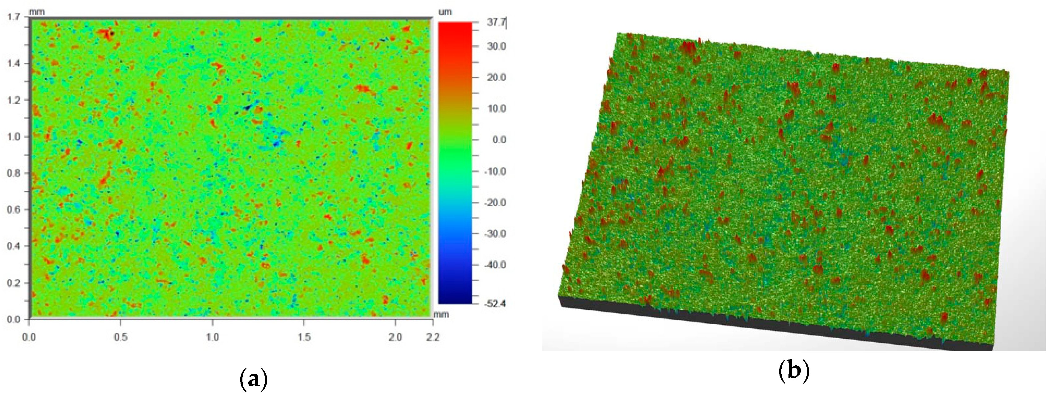
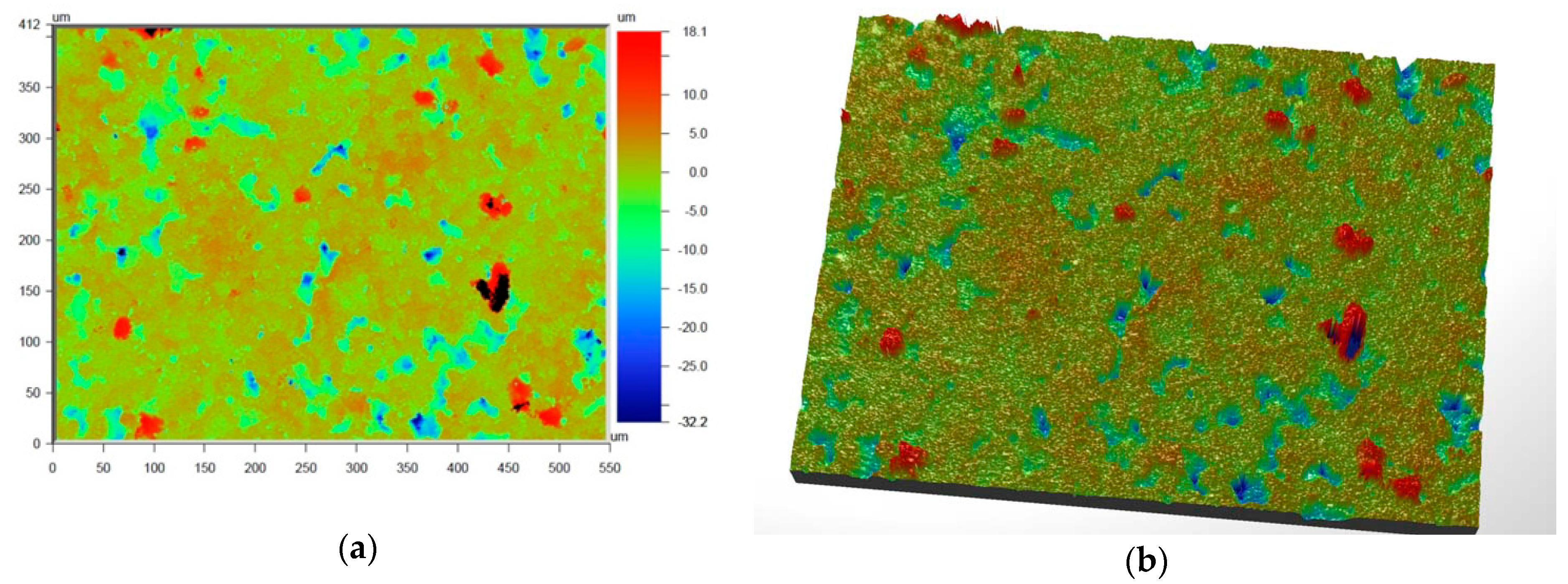
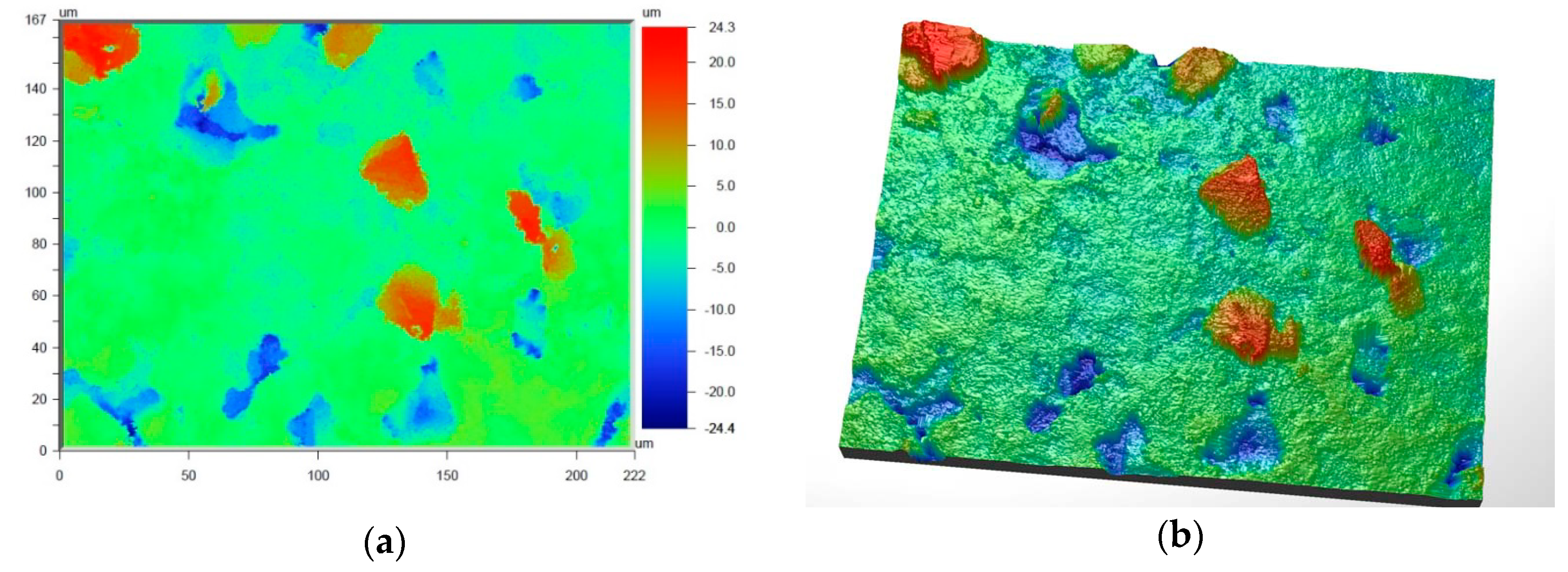
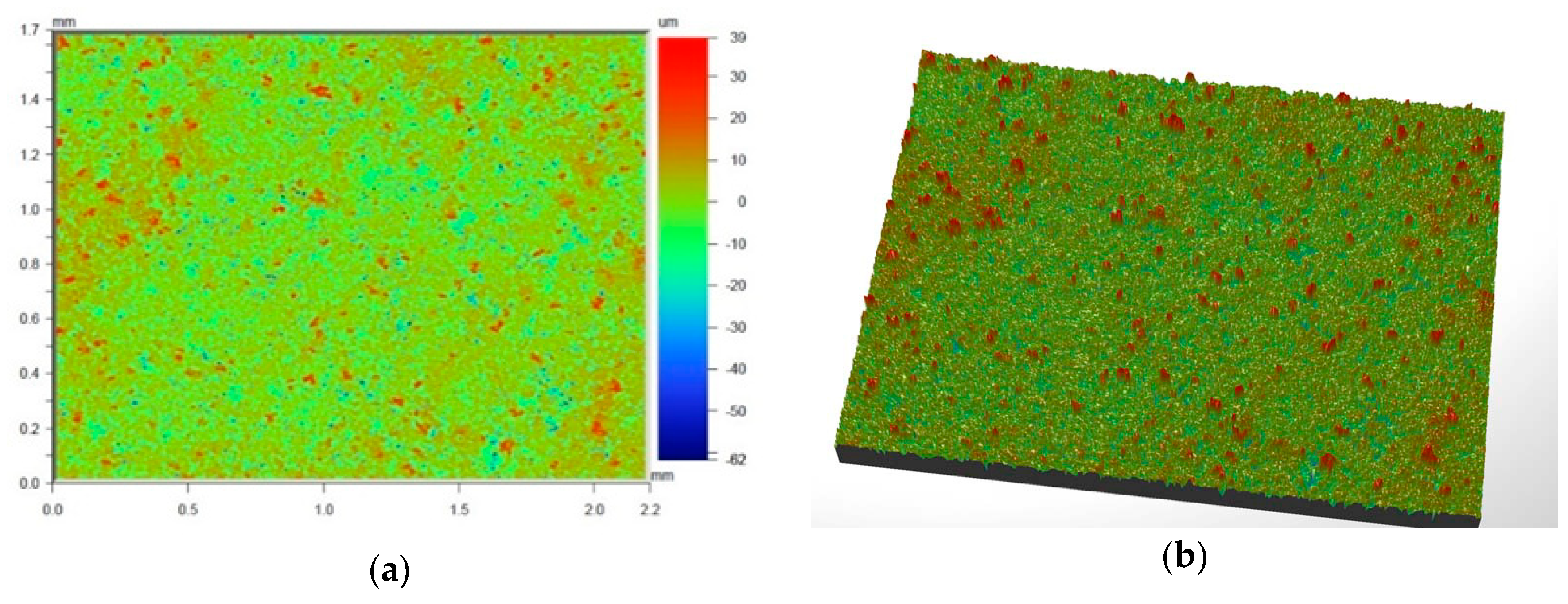
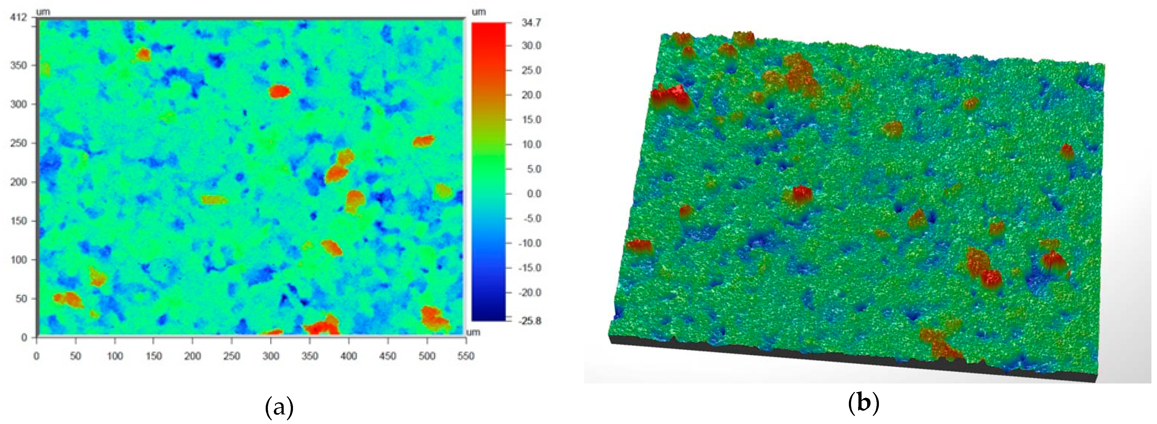
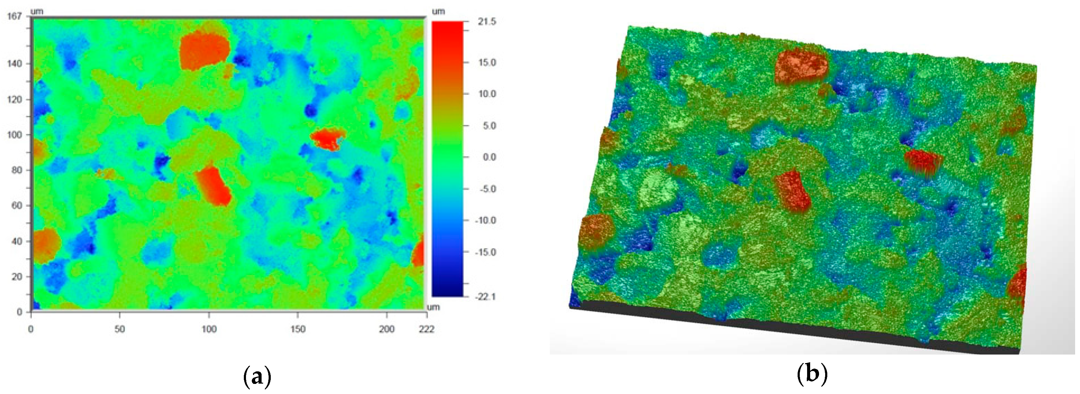
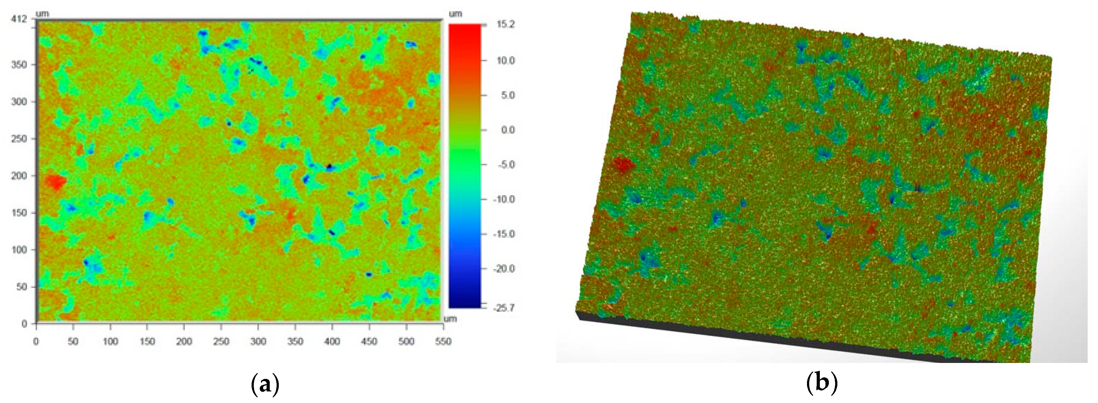
The surface roughness of the prime coat was examined using a Wyko NT9300 optical profilometer, at magnitudes of 2.9, 11.5, and 28.4. Based on the surface scans, the roughness of the surface in contact with the metal was tested, i.e., Ra (average roughness) and Rq (maximum roughness height). Tomography tests were performed using a Skyscan 1172 X-ray micro-CT. Samples were scanned at 180° rotation, and data were recorded every 0.4°. The pixel values of all samples ranged from 7.5 to 8.3 µm.
The fractures of samples of SiC-based shell molds at the output phase were observed by a Hitachi TM-1000 SEM using an accelerating voltage of 15 kV. Samples were examined using backscattered electron (BSE) mode under a low vacuum (5 Pa).
3. Results and Discussion
The powders exhibited high clarity, as confirmed by the chemical composition (XRF) results presented in
Table 2. The total contaminants present in SiC F400 did not exceed 0.6 wt.% and included phosphorous in the form of P
2O
5 (0.32 wt.%) and calcium in the form of CaO (0.26 wt.%).
The XRD results showed that this was a single-phase material, in accordance with PDF 731664 and 291128 data sheets and in agreement with previous results [
14,
15].
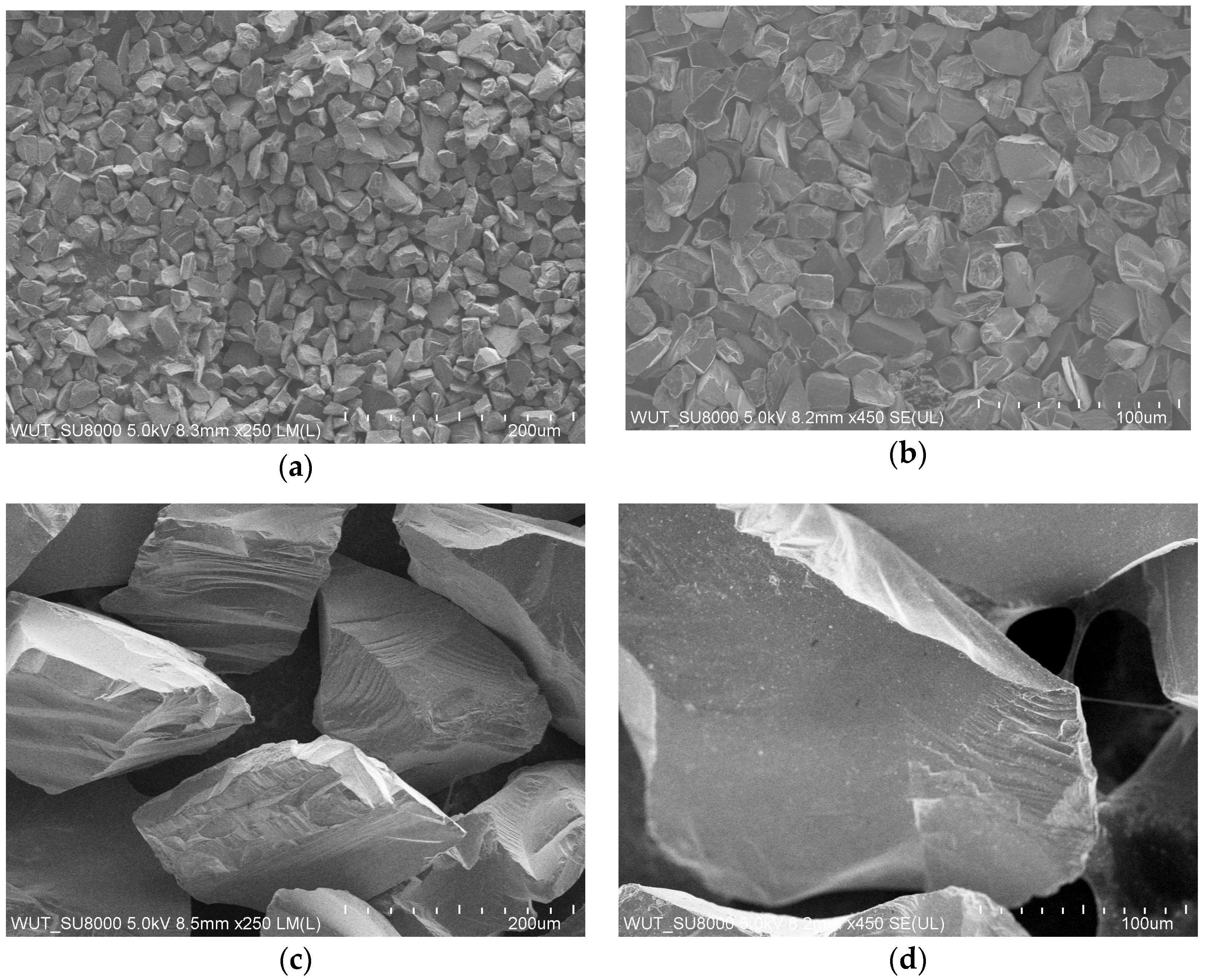
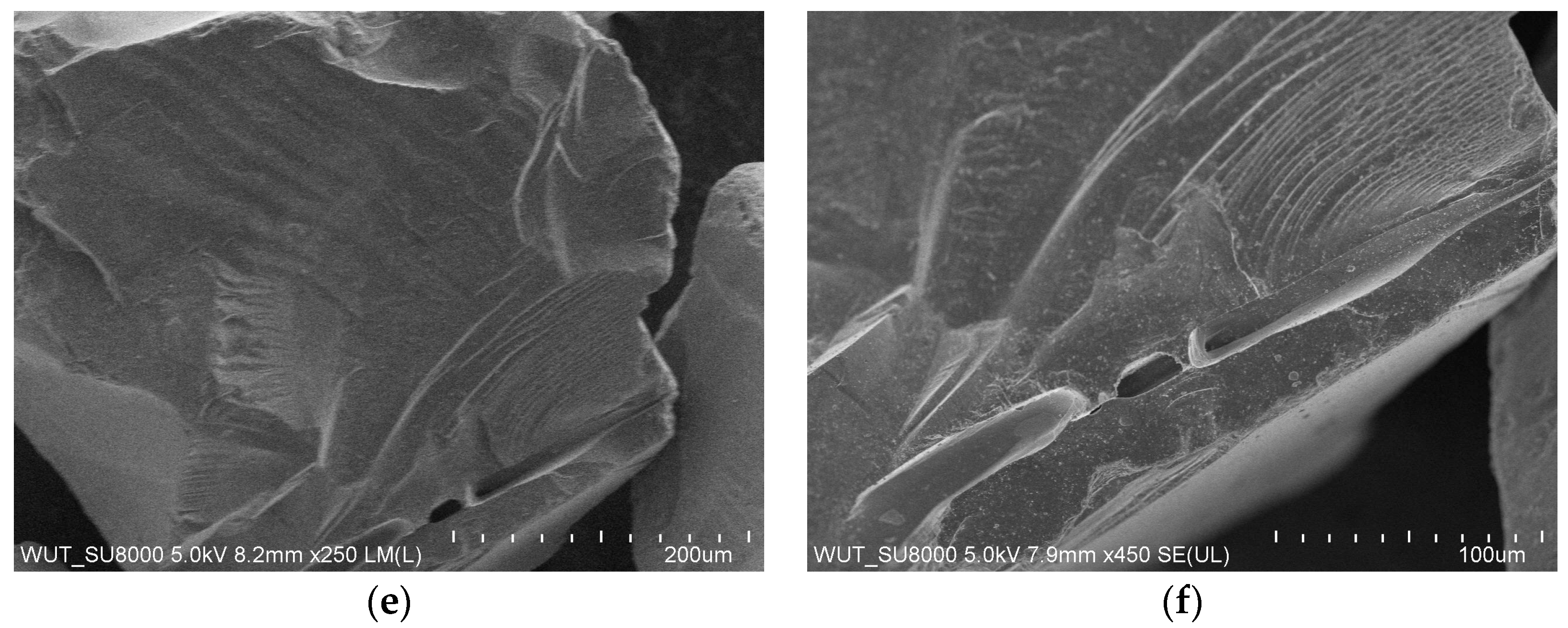
Figure 3 presents an image of the morphology of the SiC-based powders, which shows that SiC grains were irregularly shaped with sharp edges, which permits a greater solid phase density in slurries compared with spherical powders. It also allows for the production of more durable wax pattern surface coatings and higher grain packing in the shell mold, which increases the mechanical strength [
35]. In industrial practice, it is also economically advantageous to use irregularly shaped powders because the use of spherical granular materials significantly increases the costs of shell molds.
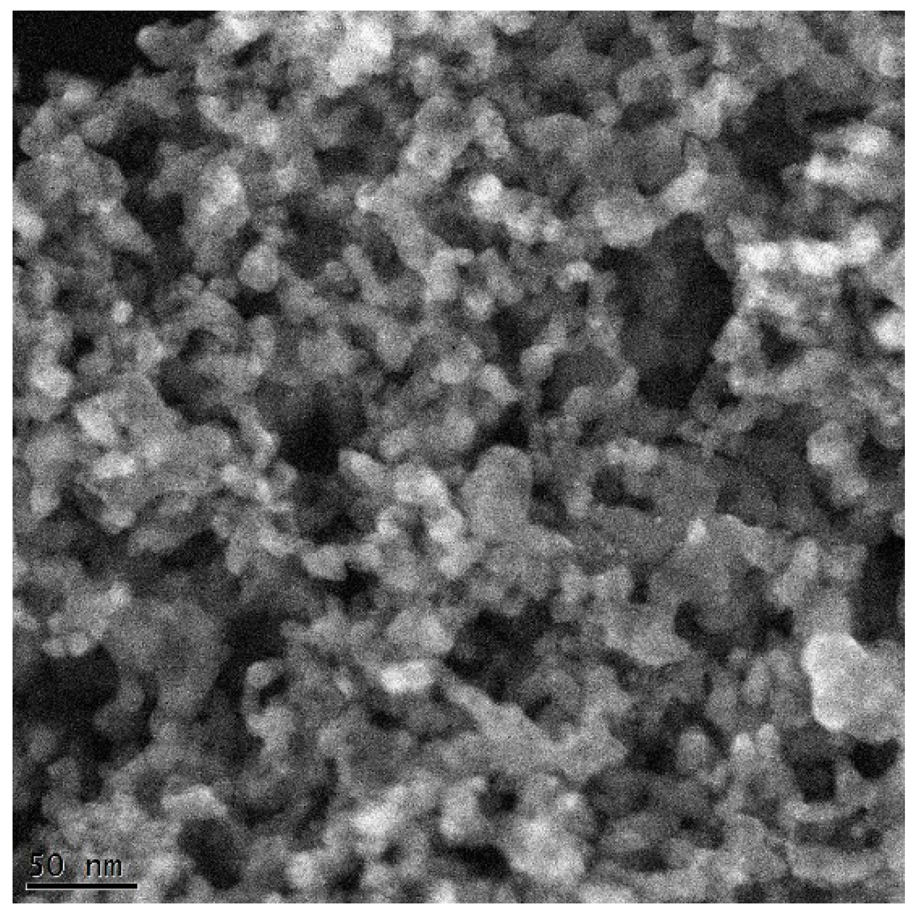
The image in
Figure 4 presents the SEM morphology of dried binder on a graphite mesh. The Al
2O
3 nanoparticles were nearly spherical, and the polymer component of the binder coated the surface of the Al
2O
3 nanoparticles and caused them to agglomerate. Based on stereological measurements, it was estimated that the average grain size of the Al
2O
3 nanoparticles was 16 nm.
Table 3 presents the technological parameters of the SiC-based ceramic slurries. In investment casting, slurries are typically prepared over 14 days because the powders have relatively large grain sizes and are homogenized with nano-oxide-based binders. Such a long mixing time allows the slurry parameters such as pH, density, and viscosity to stabilize.
The densities of slurries used for the first two layers and structural layers of shell mold were, respectively, 2.1 and 1.9 g/cm3, which was an insignificant difference. Both slurries had a slightly alkaline pH, which is a safe pH for workers who may be exposed to slurries in a manufacturing environment. Similar amounts of slurry were placed on a plate after 120 s due to only a 5 wt.% difference of the solid phase. For the same reason, the thickness of the layer made from the slurry with 65 wt.% solid phase was lower than the slurry intended for layers 1 and 2 of the shell mold.
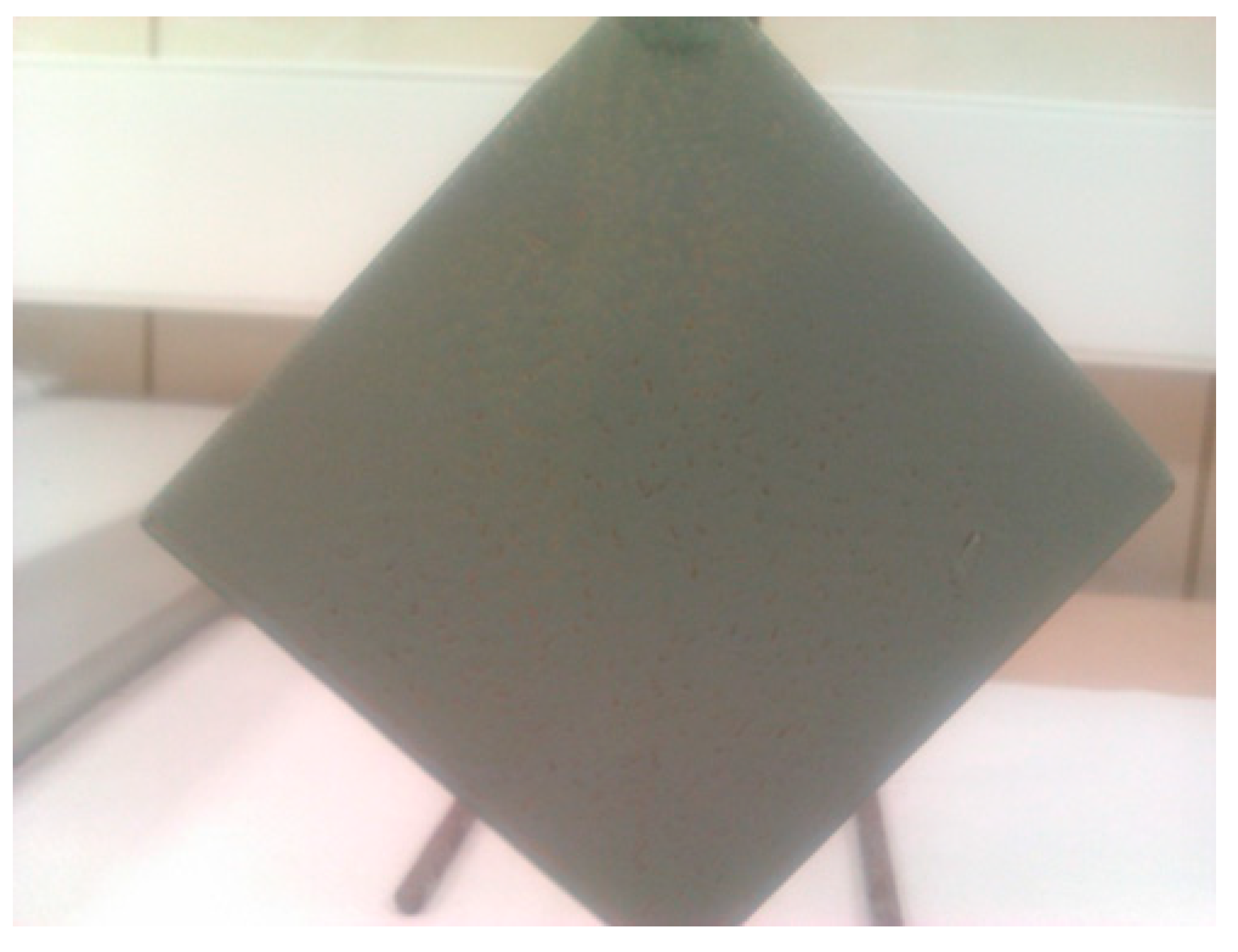
Plate weight tests were used to visually examine the slurry adhesion to a copper plate after drying, and the uniformity of the coating surface and edges, adhesion, and strength of the fabricated layer were examined. The prepared SiC-based slurries provided a good coating of the plate and its corners, without any streaks or air-bubbles (
Figure 5). Thus, it was assumed they could also be applied for wax casting patterns. This was confirmed during the fabrication of shell molds, and the stable ceramic slurry generated uniform and durable layers on both the angles and edges of flat surfaces.
The slurries had different densities, and the obtained values were within the range required by investment casting. The viscosity of slurries used for the prime coat of shell molds should be in the range of 25–40 s, and the Zahn Cup#4 efflux time for slurries intended for the structural layers of shell molds should be dozens of seconds. The prepared slurries met these requirements for casting materials (
Table 3).
Table 4 presents the mechanical properties of samples PW1, PW2, and PW3 as the average values from 20 measurements for each state of the shell mold. The PW1 series had the highest bending mechanical strength (2.28 MPa) and the highest Young’s modulus (207.66 MPa) because of the adhesion of the polymer binder to SiC grains and the uniform coating which resulted in a low number of material defects. Increasing the heating temperature (burnout) to 700 °C decreased the bending mechanical strength and Young’s modulus of the PW2 samples. This was caused by the evaporation of chemically bound water and the beginning of the burnout of the binder organic compounds, which were responsible for the relatively high mechanical strength of samples after dewaxing. The resulting defects nearly halved the mechanical strength from 2.28 to 1.21 MPa. The PW3 samples, annealed at 1200 °C/1 h, displayed a higher σ (2.03 MPa) and E (182.51 MPa) compared with the PW2 series due to the initiation of ceramic powder sintering in the material, analogous to a previous study.
The results also indicate that thermal treatment of the shell molds increased the Weibull’s modulus from 6.87 to 9.94, but further heating decreased this parameter to 5.36. The value of m depends on the quantity, concentration, and size of defects. For the PW3 samples, the low Weibull’s modulus was impacted by the high number of defects and their irregular distribution. In ceramic materials, Weibull’s modulus typically ranges from 5 < m < 30. The current materials are porous and contain many defects; however, the obtained m values for PW1–PW3 samples fall within this specified range. Thus, they share characteristics of both porous materials and ceramic shell molds [
16].
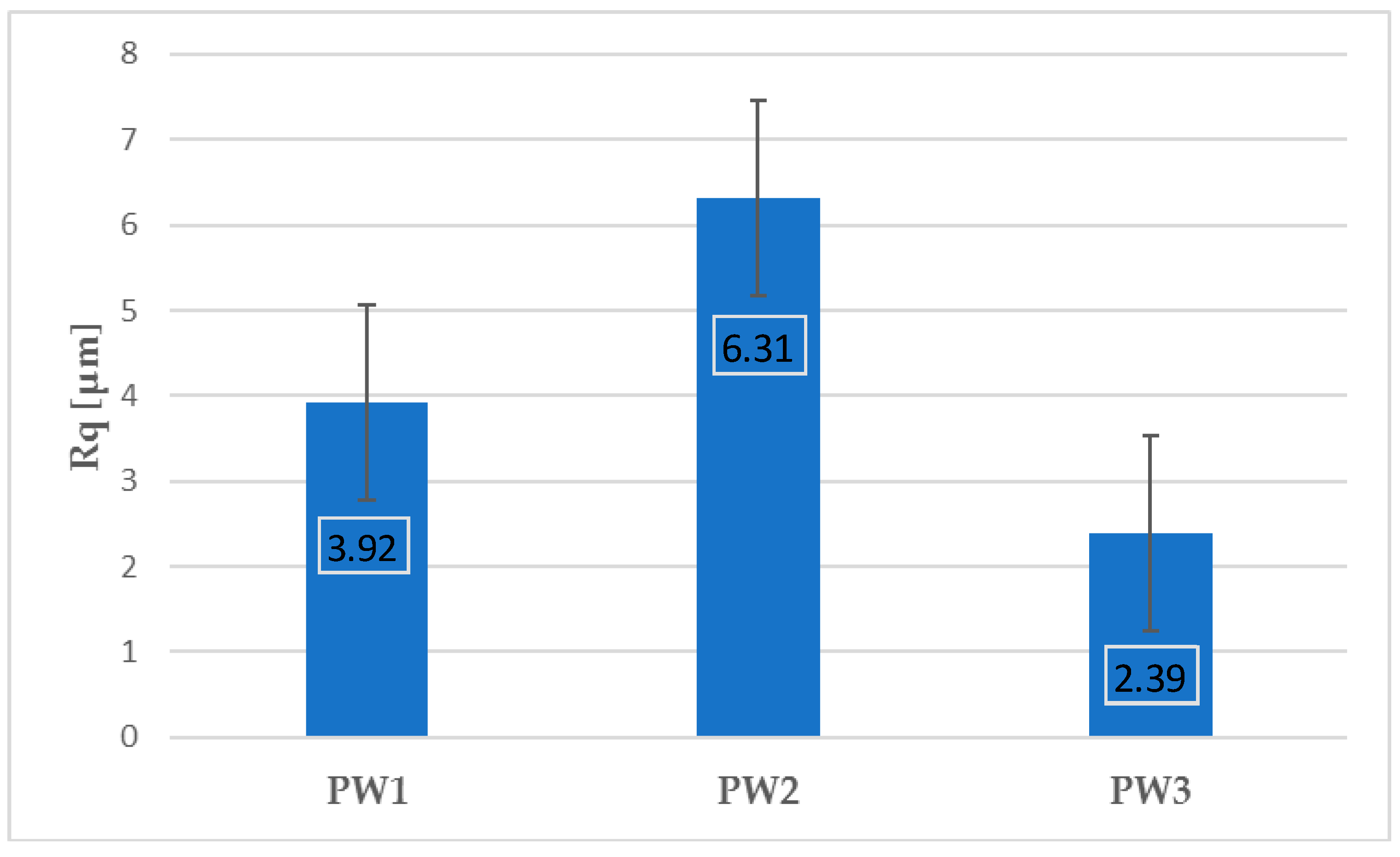
Figure 6 and
Figure 7 present the values of Ra and Rq for the prime coat, i.e., exposed to a wax pattern and to liquid metal during casting. In the aviation industry, castings should have moderate roughness values, i.e., Ra and Rq from 1 µm to 5 µm, and this level of roughness is determined by the prime coat of the ceramic shell mold, in particular after burnout preheating at 1200 °C.
Figure 6 and
Figure 7 show that the obtained values of Ra and Rq meet the requirements specified by the aviation industry.
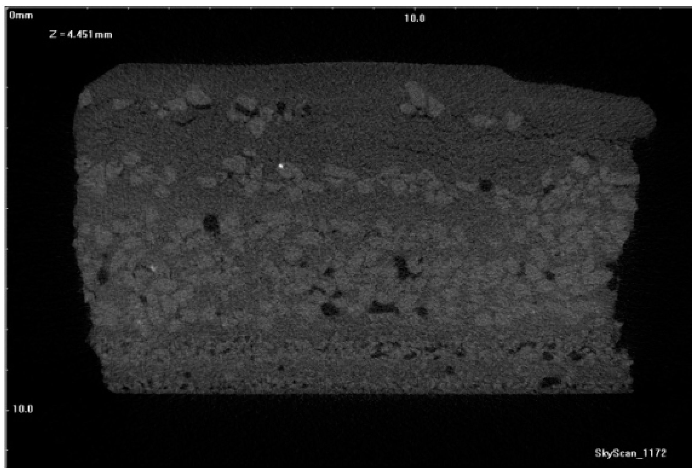
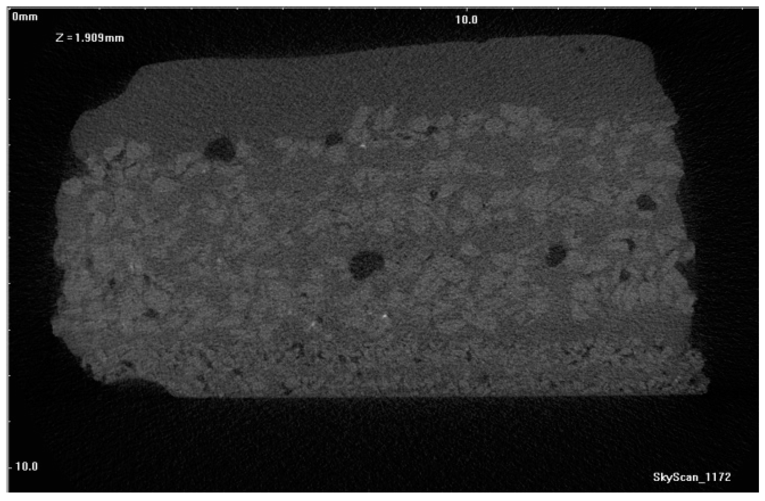
Figure 17,
Figure 18 and
Figure 19 show tomograms of the fractures of PW1, PW2, and PW3 sample shell molds. The images show that the binder coated the SiC F400 and SiC F40 and F80 particles in individual shell mold layers. After dewaxing, PW1 contained pores and individual fractures in its outer structural layers. As a result, a compact material with a relatively low number of defects was obtained (
Figure 17). Burnout preheating at 700 °C/1 h increased both the number and diameter of pores in the material (
Figure 18).
Further burnout preheating of the materials at 1200 °C/1 h formed macroscopic discontinuities in the penultimate layer and generated Al
2O
3 nanoparticles at the edges of sprinkling grains. Upon increasing the preheating temperature, a growing number of pores was generated with a stochastic distribution (
Figure 17). The reasons for defect generation, in particular in the sample annealed at 1200 °C (PW3), were due to a low interaction among SiC grains and aluminum oxide nanoparticles, due to the different chemical nature of the two compounds. The different sintering temperatures of Al
2O
3 (>1500 °C), and porous SiC (mostly 1200–1300 °C), the conditions of thermal processes of Al
2O
3 and SiC, and the significantly different grain sizes of the two solid phases also affected the defect generation [
14,
15].
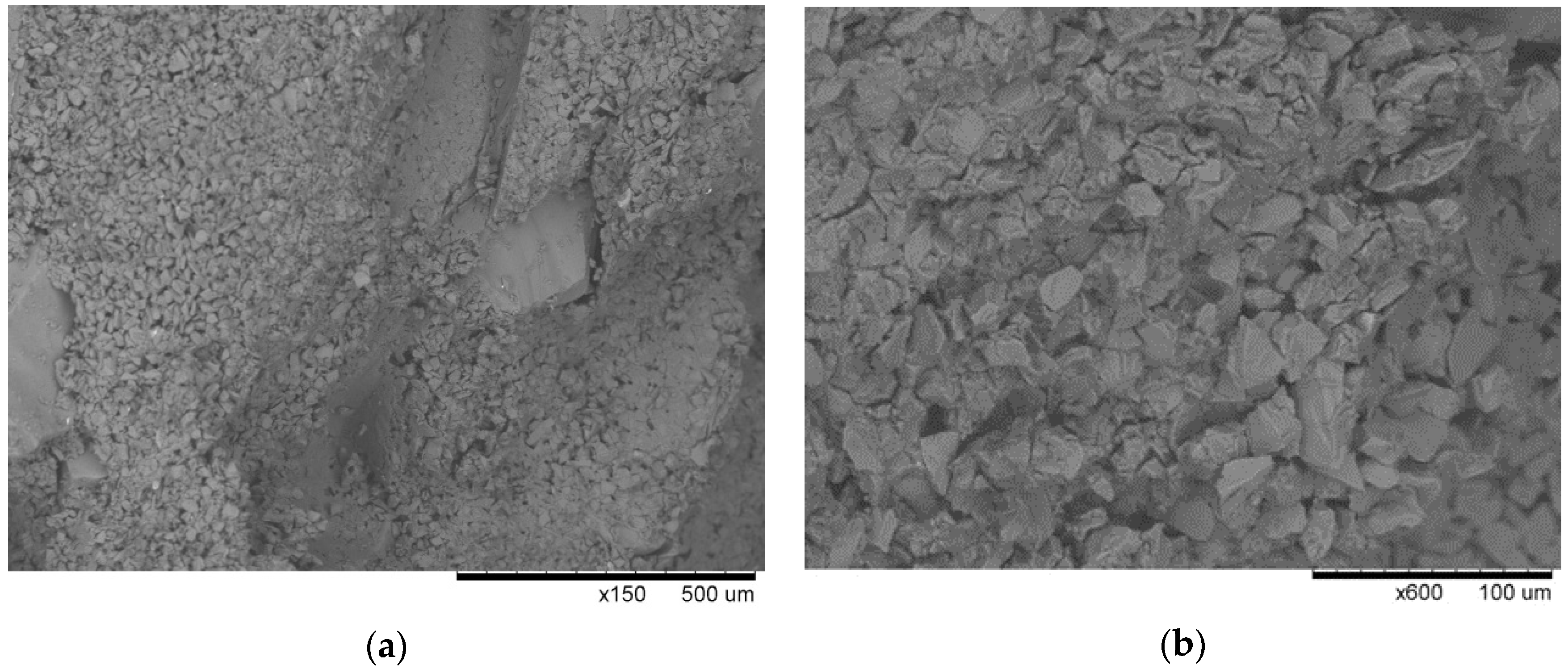
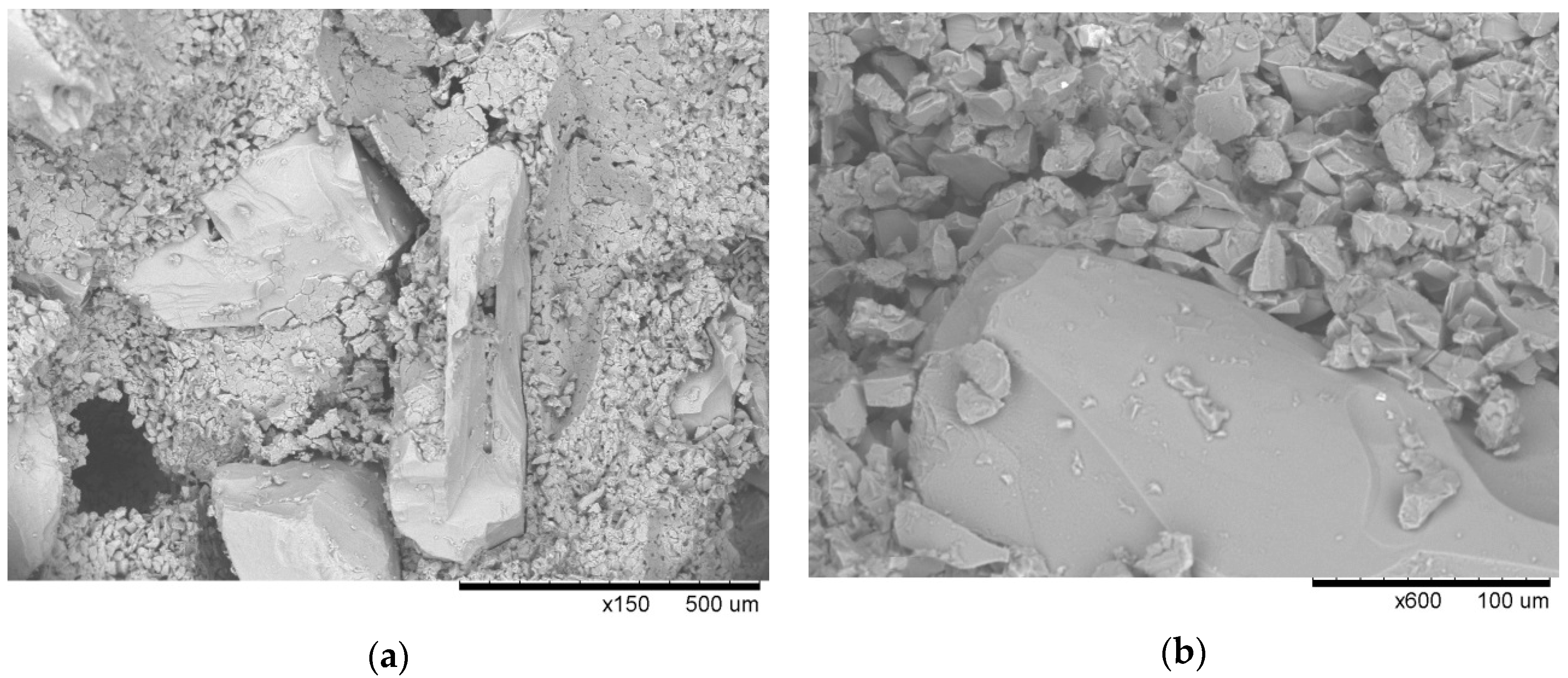
The microtomogram results were confirmed by scanning microscopy, and
Figure 20,
Figure 21 and
Figure 22 present the morphologies of PW1, PW2, and PW3 samples.
The PW1 sample shows that the large material grains of SiC F40 and F80 were surrounded by smaller SiC and binder particles. The morphology of PW1 was compact and had a small number of macroscopic defects. It can thus be assumed that the polymer binder containing colloidal Al
2O
3 contained SiC particles with good adhesion and wettability at the dewaxing stage. No binder decomposed at the dewaxing temperature, which prevented it from coating a significant number of SiC particles (
Figure 22). Increasing the burnout preheating temperature resulted in significant polymer decomposition, dehydration (to 200 °C), and dehydroxylation of water (up to 600 °C) in PW2. The evaporation of water from the material generated many large pores (
Figure 21). Further burnout preheating at 1200 °C completely decomposed the organic components of the binder and generated larger material defects, i.e., pores and fractures, in all layers of the PW3 sample. The results of the tomography tests and SEM microstructure confirmed the physical and mechanical properties of PW1, PW2, and PW3 samples.
4. Conclusions
The objective of this work was to obtain stable slurries for preparing individual layers of SiC-based shell molds, using a SiC-based ceramic slurry without grain growth inhibitor for the prime coat. Additionally, we also sought to fabricate and examine SiC-based shell molds. SiC-based slurries with a relatively high ceramic powder content and SiC concentrations of 65–70 wt.% were obtained. Both slurries met the required technological parameters and were characterized by a high viscosity, as determined by the Zahn cup #4 outflow time. The viscosity of the slurry used for the prime coat was 33.1 s and 14.8 s for the structural layers. The slurries were also characterized by the complete and defect-free coating of a copper plate, flat areas, angles, and edges of wax patterns and individual shell mold layers. The SiC F80–F40 sprinkling grains exhibited good adhesion to the slurry and did not detach after drying. The binder containing Al2O3 nanoparticles could be used in investment casting to replace binders that contain colloidal silica. The prepared original investment casting systems for prime coat, sealing coat, and structural layers are likely to be implemented in industrial practice.
Three series of samples were prepared from SiC-based shell forms fabricated by a lost-wax method: after dewaxing (PW1), after burnout preheating at 700 °C/1 h (PW2), and after annealing at 1200 °C/1 h (PW3). The profilometry results showed that the obtained values of Ra and Rq of the prime coat of SiC-based shell mold did not exceed 5 µm, meaning that they met the requirements specified by the aviation industry.
The fabricated shell molds had a bending mechanical strength within the range of 1.21–2.28 MPa, a Young’s modulus of 102.97–207.66 MPa, and a Weibull’s modulus of 5.36–9.94. The properties were affected by the thermal treatment temperature.
The PW1 samples displayed the highest mechanical bending strength of 2.28 MPa and the highest Young’s modulus (207.66 MPa), which ensured good adhesion and wetting of the SiC grains by the polymer binder. Consequently, the materials fabricated from this series had few defects.
The fabricated shell molds met the requirements specified for industrial shell molds, and both the investment casting systems and SiC-based shell molds have promising properties and may be an alternative to current materials. This work constitutes the basis for further studies for producing SiC-based shell molds on a larger scale. Thus, industrial-scale tests must be performed, combined with follow-up shell mold testing, casting test runs, and the evaluation of molds and investment castings.


