Deformation Induced Soft and Hard Lath Packets Enhance Ductility in Martensitic Steels

 and
and 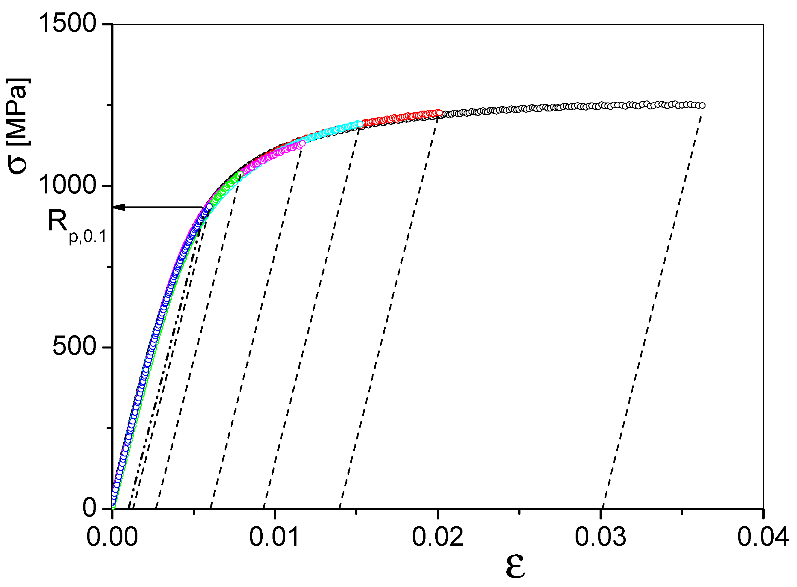
Abstract
1. Introduction
2. Experimental
2.1. Specimens
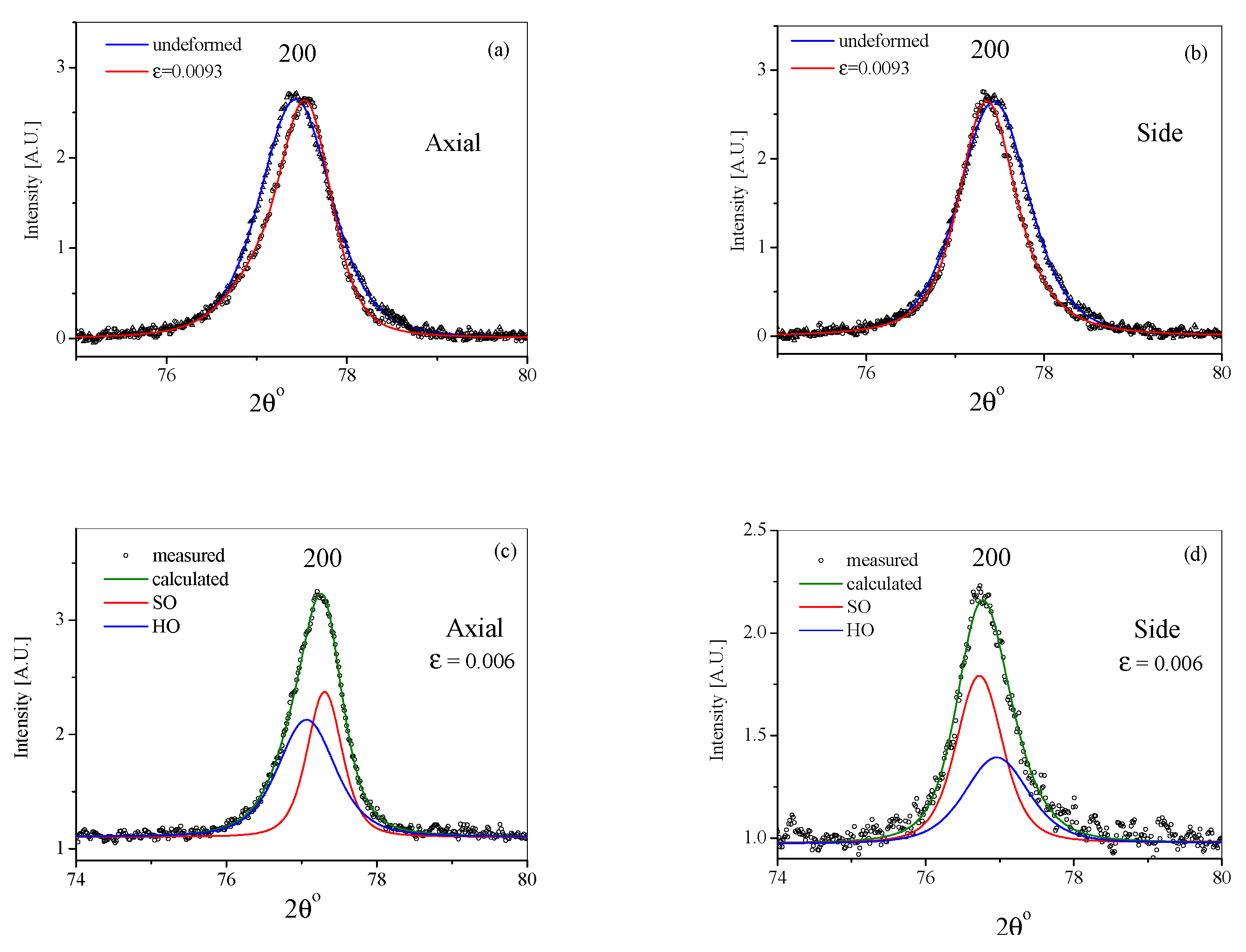
2.2. X-ray Diffraction Experiments
2.3. Nano- and Micro-Indentation Measurements
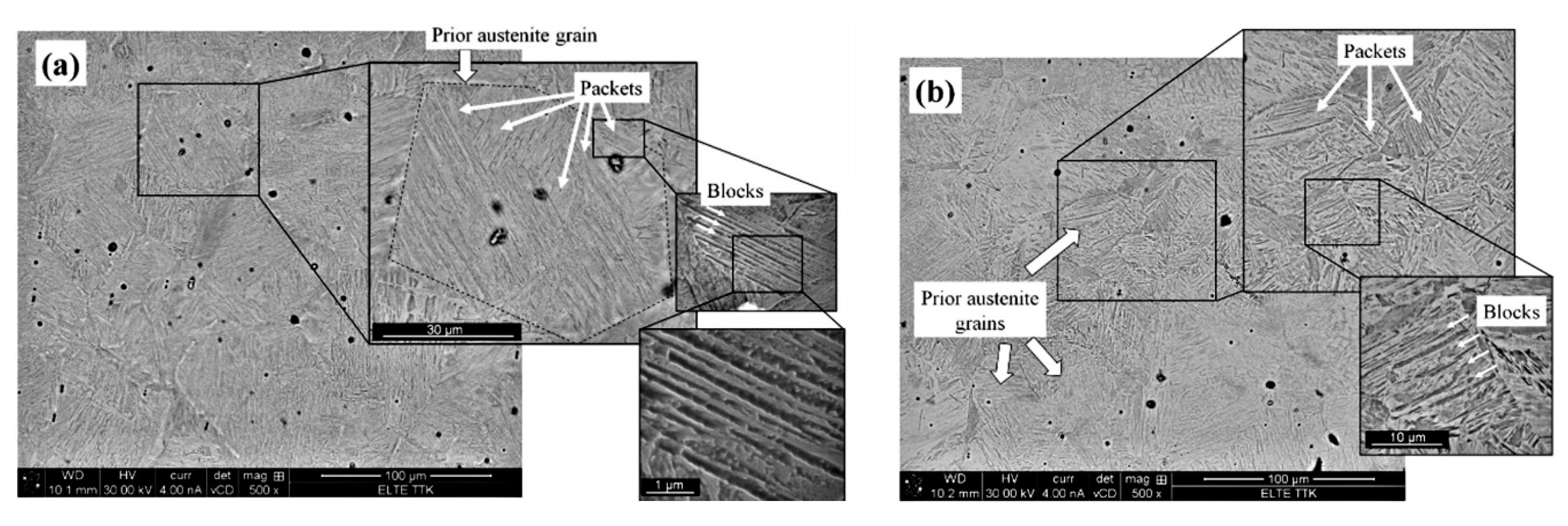
2.4. Scanning Electron Microscopy Investigations
3. Evaluation of the Diffraction Patterns
4. Results and Discussion
4.1. Plastic Strain Induced Long-Range Internal Stresses
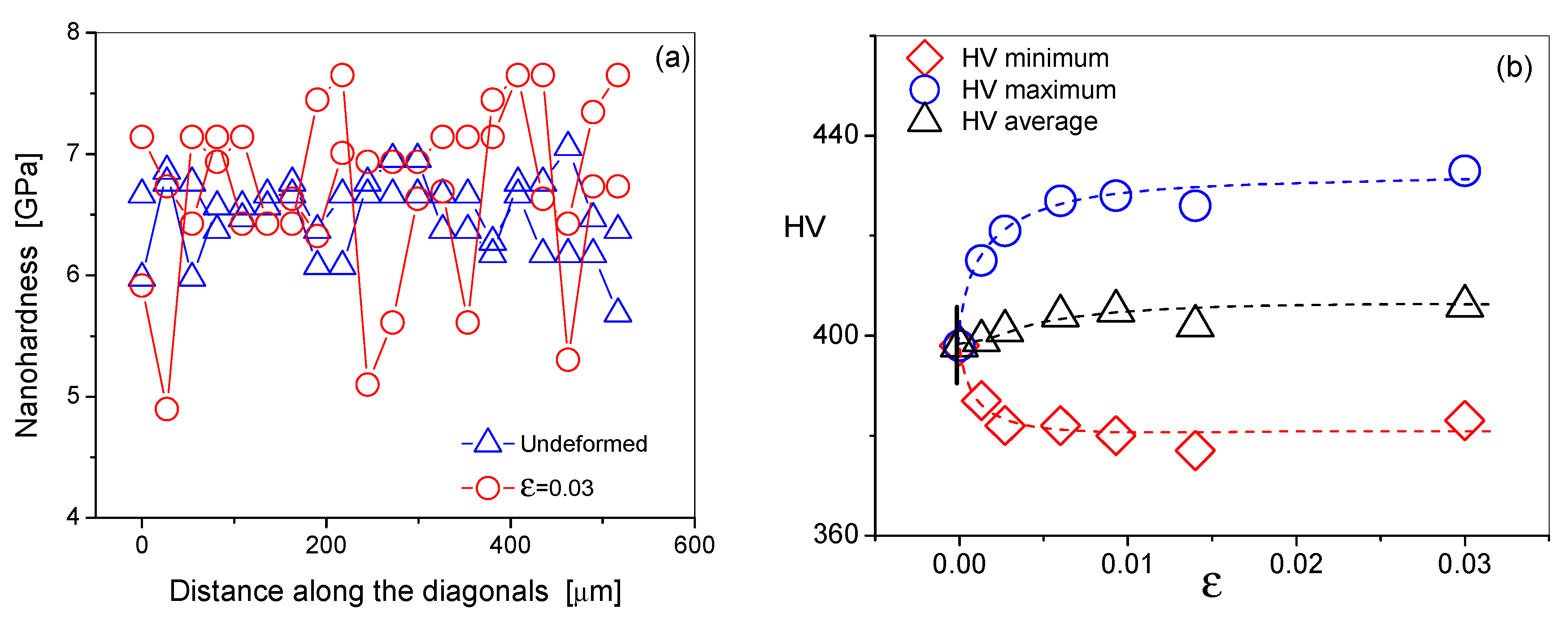
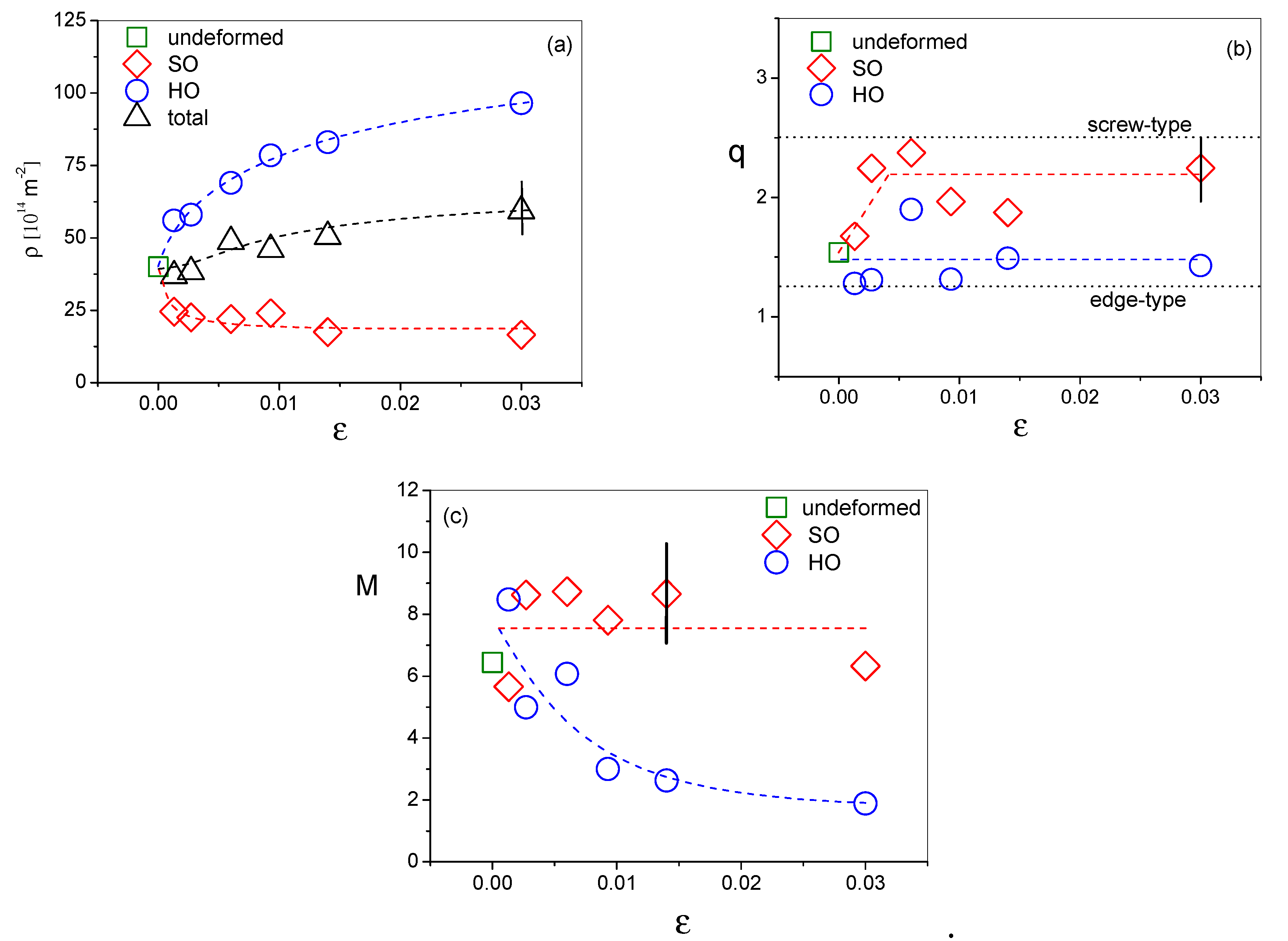
4.2. The Local and the Average Dislocation Densities as a Function Plastic Strain
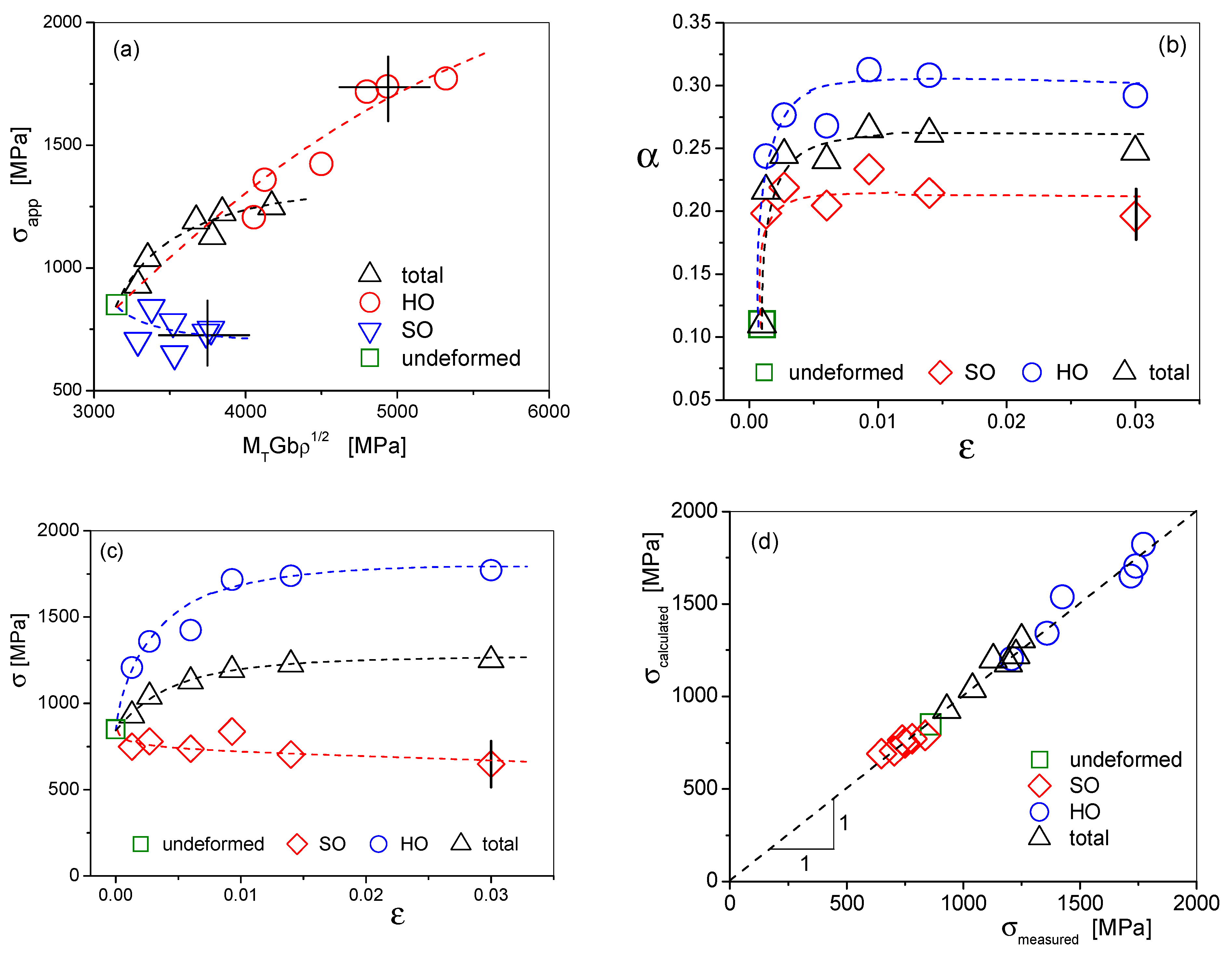
4.3. Correlation between the Stress-Strain Response and the Dislocation Density and Arrangement as a Function of Strain
4.4. A Direct Evidence for the Decomposition into the Composition of Soft and Hard Lath-packets Induced by Plastic Strain
5. Conclusions and Summary
Author Contributions
Funding
Acknowledgments
Conflicts of Interest
References
- Krauss, G. Martensite in steel: Strength and structure. Mater. Sci. Eng. 1999, 273–275, 40–57. [Google Scholar] [CrossRef]
- Krauss, G.; Marder, A.R. The morphology of martensite in iron alloys. Metall. Trans. 1971, 2, 2343–2357. [Google Scholar] [CrossRef]
- Krauss, G. Tempering of lath martensite in low and medium carbon steels: Assessment and challenges. Steel Res. Int. 2017, 87, 1700038. [Google Scholar] [CrossRef]
- Bhadeshia, H.K.D.H.; Honeycombe, R. Steels: Microstructure and Properties, 3rd ed.; Butterworth-Heinemann: Oxford, UK, 2006; pp. 95–128. ISBN 9780750680844. [Google Scholar]
- Morito, S.; Tanaka, H.; Konishi, R.; Furuhara, T.; Maki, T. The morphology and crystallography of lath martensite in Fe-C alloys. Acta Mater. 2003, 51, 1789–1799. [Google Scholar] [CrossRef]
- Kitahara, H.; Ueji, R.; Tsuji, N.; Minamino, Y. Crystallographic features of lath martensite in low-carbon steel. Acta Mater. 2006, 54, 1279–1288. [Google Scholar] [CrossRef]
- Swarr, T.; Krauss, G. The effect of structure on the deformation of as-quenched and tempered martensite in an Fe-0.2 pct C alloy. Metall. Trans. 1976, A7, 41–48. [Google Scholar] [CrossRef]
- Morito, S.; Adachi, Y.; Ohba, T. Morphology and crystallography of sub-blocks in ultra-low carbon lath martensite steel. Mater. Trans. 2009, 50, 1919–1923. [Google Scholar] [CrossRef]
- Morito, S.; Huang, X.; Furuhara, T.; Maki, T.; Hansen, N. The morphology and crystallography of lath martensite in alloy steels. Acta Mater. 2006, 54, 5323–5331. [Google Scholar] [CrossRef]
- Zhang, P.; Chen, Y.; Xiao, W.; Ping, D.; Zhao, X. Twin structure of the lath martensite in low carbon steel. Prog. Nat. Sci. Mater. Int. 2016, 26, 169–172. [Google Scholar] [CrossRef]
- Kurdjumov, G.V.; Sachs, G. Über den Mechanismus der Stahlhärtung. Zeitschrift Physik 1930, 64, 325–343. [Google Scholar] [CrossRef]
- Michiuchi, M.; Nambu, S.; Ishimoto, Y.; Inoue, J.; Koseki, T. Relationship between local deformation behavior and crystallographic features of as-quenched lath martensite during uniaxial tensile deformation. Acta Mater. 2009, 57, 5283–5291. [Google Scholar] [CrossRef]
- Nambu, S.; Michiuchi, M.; Ishimoto, Y.; Asakura, K.; Inoue, J.; Koseki, T. Transition in deformation behavior of martensitic steel during large deformation under uniaxial tensile loading. Scr. Mater. 2009, 60, 221–224. [Google Scholar] [CrossRef]
- Ghassemi-Armaki, H.; Chen, P.; Bhat, S.; Sadagopan, S.; Kumar, S.; Bower, A. Microscale-calibrated modeling of the deformation response of low-carbon martensite. Acta Mater. 2013, 61, 3640–3652. [Google Scholar] [CrossRef]
- Mine, Y.; Hirashita, K.; Takashima, H.; Matsuda, M.; Takashima, K. Micro-tension behaviour of lath martensite structures of carbon steel. Mater. Sci. Eng. 2013, A560, 535–544. [Google Scholar] [CrossRef]
- Kwak, K.; Mayama, T.; Mine, Y.; Takashima, K. Anisotropy of strength and plasticity in lath martensite steel. Mater. Sci. Eng. 2016, A674, 104–116. [Google Scholar] [CrossRef]
- Kapp, M.W.; Hohenwarter, A.; Wurster, S.; Yang, B.; Pippan, R. Anisotropic deformation characteristics of an ultrafine- and nanolamellar pearlitic steel. Acta Mater. 2016, 106, 239–248. [Google Scholar] [CrossRef]
- Funkenbusch, P.D.; Lee, J.K.; Courtney, T.H. Ductile Two-Phase Alloys: Prediction of Strengthening at High Strains. Metall. Trans. 1987, A18, 1249–1256. [Google Scholar] [CrossRef]
- Hangen, N.; Raabe, D. Modelling of the yield stregth of a heavily wire drawn Cu-20%Nb composite by use of a modified linear rule of mixture. Acta Metall. Mater. 1995, 43, 4075–4082. [Google Scholar] [CrossRef]
- Russell, A.M.; Chumbley, L.S.; Tian, Y. Deformation Processed Metal-Metal Composites. Adv. Eng. Mater. 2000, 2, 11–22. [Google Scholar] [CrossRef]
- Bouaziz, O.; Zurob, H.; Huang, M. Driving Force and Logic of Development of Advanced High Strength Steels for Automotive Applications. Int. Steel Res. 2013, 84, 937–947. [Google Scholar] [CrossRef]
- Ungár, T.; Harjo, S.; Kawasaki, T.; Tomota, Y.; Ribárik, G.; Shi, Z. Composite behavior of martensite steels induced by plastic strain, a new paradigm for the elastic-plastic response of martensitic steels. Metall. Mater. Trans. 2017, A48, 159–167. [Google Scholar] [CrossRef]
- Harjo, S.; Kawasaki, T.; Tomota, Y.; Gong, W.; Aizawa, K.; Shi, Z.; Tichy, G.; Ungár, T. Work hardening, dislocation structure and load partitioning in lath-martensite determined by in situ neutron diffraction line profile analysis. Metall. Mater. Trans. 2017, A48, 4080–4092. [Google Scholar] [CrossRef]
- Mughrabi, H. Dislocation wall and cell structures and long-range internal stresses in deformed metal crystals. Acta Metall. 1983, 31, 1367–1379. [Google Scholar] [CrossRef]
- Ungár, T.; Mughrabi, H.; Rönnpagel, D.; Wilkens, M. X-ray line-broadening study of the dislocation cell structure in deformed [001]-orientated copper single crystals. Acta Metall. 1984, 32, 333–342. [Google Scholar] [CrossRef]
- Mughrabi, H.T.; Ungár Kienle, T.W.; Wilkens, M. Long-range internal stresses and asymmetric X-ray line-broadening in tensile-deformed [001]-orientated copper single crystals. Philos. Mag. 1986, A53, 793–813. [Google Scholar] [CrossRef]
- Ungár, T.; Ott, S.; Sanders, P.G.; Borbély, A.; Weertman, J.R. Dislocations, grain size and planar faults in nanostructured copper determined by high resolution X-ray diffraction and a new procedure of peak profile analysis. Acta Mater. 1998, 46, 3693–3699. [Google Scholar] [CrossRef]
- Ungár, T.; Gubicza, J.; Ribárik, G.; Borbély, A. Crystallite size distribution and dislocation structure determined by diffraction profile analysis: Principles and practical application to cubic and hexagonal crystals. J. Appl. Cryst. 2001, 34, 298–310. [Google Scholar] [CrossRef]
- Ribárik, G.; Gubicza, J.; Ungár, T. Correlation between strength and microstructure of ball-milled Al-Mg alloys determined by X-ray diffraction. Mater. Sci. Eng. 2004, A387–A389, 343–347. [Google Scholar] [CrossRef]
- Ribárik, G.; Ungár, T. Characterization of the microstructure in random and textured polycrystals and single crystals by diffraction line profile analysis. Mater. Sci. Eng. 2010, A528, 112–121. [Google Scholar] [CrossRef]
- Ribárik, G.; Jóni, B.; Ungár, T. Global optimum of microstructure parameters in the CMWP line-profile-analysis method by combining Marquardt-Levenberg and Monte-Carlo procedures. J. Mater. Sci. 2019, 35, 1508–1514. [Google Scholar] [CrossRef]
- Ungár, T.; Tichy, G.; Gubicza, J.; Hellmig, R.J. Correlation between subgrains and coherently scattering domains. Powder Diffr. 2005, 20, 366–375. [Google Scholar] [CrossRef]
- Warren, B.E. X-ray Diffraction; Dover Publ.: New York, NY, USA, 1990; p. 269. [Google Scholar]
- Wilkens, M. Theoretical aspects of kinematical X-ray diffraction profiles from crystals containing dislocation distributions. In Fundamental Aspects of Dislocation Theory Volume II; Simmons, J.A., De Wit, R., Bullough, R., Eds.; National Bureau of Standards (US) Special Publication No. 317; National Institute of Standards and Technology: Gaithersburg, MD, USA, 1970; pp. 1195–1221. [Google Scholar]
- Ungár, T.; Tichy, G. The effect of dislocation contrast on X-ray line profiles in untextured polycrystals. Phys. Status Solidi 1999, A171, 425–434. [Google Scholar] [CrossRef]
- Ungár, T.; Dragomir, I.; Révész, Á.; Borbély, A. The contrast factors of dislocations in cubic crystals: The dislocation model of strain anisotropy in practice. J. Appl. Crystallogr. 1999, 32, 992–1002. [Google Scholar] [CrossRef]
- Ungár, T.; Li, L.; Tichy, G.; Pantleon, W.; Choo, H.; Liaw, P.K. Work softening in nanocrystalline materials induced by dislocation annihilation. Scr. Mater. 2011, 64, 876–879. [Google Scholar] [CrossRef]
- Devincre, B.; Hoc, T.; Kubin, L. Dislocation mean free paths and strain hardening of crystals. Science 2008, 320, 1745–1748. [Google Scholar] [CrossRef]
- Sestak, B.; Seeger, A. The relationship between the work-hardening of B.C.C. and F.C.C. metals. Phys. Status Solidi 1971, B43, 433–444. [Google Scholar] [CrossRef]
- Sestak, B.; Seeger, A. Gleitung und Verfestigung in kubisch raumzentrierten Metallen und Legierungen I-III. Zeitschrift Metallkunde 1978, 69, 425–432. [Google Scholar]
- Taylor, G.I. The mechanism of plastic deformation of crystals, Part I Theoretical. Proc. R. Soc. Lond. 1934, A145, 362–387. [Google Scholar]
- Arlazarov, A.; Bouaziz, O.; Hazotte, A.; Gouné, M.; Allain, S. Characterization and Modeling of Manganese Effect on Strength and Strain Hardening of Martensitic Carbon Steels. Int. Iron Steel Inst. Jpn. 2013, 53, 1076–1080. [Google Scholar] [CrossRef]
- Mughrabi, H. A two-parameter description of heterogeneous dislocation distributions in deformed metal crystals. Mater. Sci. Eng. 1987, 85, 15–31. [Google Scholar] [CrossRef]
- Schafler, E.; Simon, K.; Bernstorff, S.; Hanák, P.; Tichy, G.; Ungár, T.; Zehetbauer, M.J. A second-order phase-transformation of the dislocation structure during plastic deformation determined by in situ synchrotron X-ray diffraction. Acta Mater. 2005, 53, 315–322. [Google Scholar] [CrossRef]
- Ungár, T.; Stoica, A.D.; Tichy, G.; Wang, X.-L. Orientation-dependent evolution of the dislocation density in grain populations with different crystallographic orientations relative to the tensile axis in a polycrystalline aggregate of stainless steel. Acta Mater. 2014, 66, 251–261. [Google Scholar] [CrossRef]
- Mughrabi, H. The α-factor in the Taylor flow-stress law in monotonic, cyclic and quasi-stationary deformations: Dependence on slip mode, dislocation arrangement and density. Curr. Opin. Solid State Mater. Sci. 2016, 20, 411–420. [Google Scholar] [CrossRef]


© 2020 by the authors. Licensee MDPI, Basel, Switzerland. This article is an open access article distributed under the terms and conditions of the Creative Commons Attribution (CC BY) license (http://creativecommons.org/licenses/by/4.0/).
Share and Cite
Ódor, É.; Jóni, B.; Ribárik, G.; Chinh, N.Q.; Ungár, T.; Szabó, P.J. Deformation Induced Soft and Hard Lath Packets Enhance Ductility in Martensitic Steels. Crystals 2020, 10, 373. https://doi.org/10.3390/cryst10050373
Ódor É, Jóni B, Ribárik G, Chinh NQ, Ungár T, Szabó PJ. Deformation Induced Soft and Hard Lath Packets Enhance Ductility in Martensitic Steels. Crystals. 2020; 10(5):373. https://doi.org/10.3390/cryst10050373
Chicago/Turabian StyleÓdor, Éva, Bertalan Jóni, Gábor Ribárik, Nguyen Quang Chinh, Tamás Ungár, and Péter J. Szabó. 2020. "Deformation Induced Soft and Hard Lath Packets Enhance Ductility in Martensitic Steels" Crystals 10, no. 5: 373. https://doi.org/10.3390/cryst10050373
APA StyleÓdor, É., Jóni, B., Ribárik, G., Chinh, N. Q., Ungár, T., & Szabó, P. J. (2020). Deformation Induced Soft and Hard Lath Packets Enhance Ductility in Martensitic Steels. Crystals, 10(5), 373. https://doi.org/10.3390/cryst10050373