Article

Fabrication of CoFe2O4 Nanowire Using a Double-Pass Porous Alumina Template with a Large Range of Pore Diameters

1
Laboratory for Nanoelectronics and NanoDevices, Department of Electronics Science and Technology, Hangzhou Dianzi University, Hangzhou 310018, China
2
Magnetism Kev Laboratory of Zhejiang Province, China Jiliang University, Hangzhou 310018, China
*
Authors to whom correspondence should be addressed.
Crystals 2020, 10(4), 331; https://doi.org/10.3390/cryst10040331
Submission received: 20 March 2020 / Revised: 13 April 2020 / Accepted: 22 April 2020 / Published: 23 April 2020
(This article belongs to the Special Issue Magnetism in Low Dimensional Structures)

Abstract

:
In this work, CoFe2O4 nanowire was fabricated by using a self-designed double-pass porous alumina template. The double-pass porous alumina template was prepared by a two-step oxidation method using a mixed acid (phosphoric acid and oxalic acid) electrolyte and polymethyl methacrylate (PMMA) filler. The combustion of aluminum foil at a high voltage has been effectively resolved by using this mixed acid electrolyte. Additionally, the range of pore diameters has been obviously increased to 230–400 nm by using PMMA as the filler, which can prevent contact between the pore and solution when removing the barrier layer. Subsequently, CoFe2O4 ferrite nanowire arrays were successfully fabricated into the double-pass porous alumina template by an electrochemical deposition method, and show an anisotropic feature of magnetic properties.

1. Introduction

Recently, one-dimensional magnetic nanomaterials such as nanowires, nanotubes, and nanorods have attracted much attention due to their potential applications in magnetic integrated nanosystems, perpendicular magnetic records, microwave absorbing, and spintronic nanodevices [1,2]. Cobalt spinel ferrite CoFe2O4 (CFO) is well known for its high coercivity, giant magnetostriction, unique light-induced coercivity change, and remarkable chemical stability. CFO has various applications, such as humidity sensors, photodetectors, biomedical, and magnetoelectric devices [3,4]. Various methods have been used to prepare ferrite magnetic nanomaterials, such as the hydrothermal method [5,6,7], sol–gel template-assisted method [8,9,10], electrochemical deposition template-assisted method [11,12,13], and physical vapor deposition template-assisted method [14,15,16]. Obviously, template-assisted methods are the most universal and effective methods. Therefore, various templates, such as mesoporous molecular sieves [17], polymer porous membranes [18], porous silicon [19], and alumina templates [20], have been widely used. Among them, the alumina template is favorable in the preparation of one-dimensional nanostructures because of its adjustable template parameters, uniform pore size, hexagonal structure arrangement, parallel pores, highly ordered structure, good physical and chemical stability, and low production cost.
In 1995, H. Masuda successfully prepared self-ordered porous anodized alumina oxide (AAO) [21] and then established a two-step anodization method to further optimize the morphology of the template. The two-step oxidation method involves etching of the oxide layer produced by the first oxidation and then a second oxidation on the aluminum surface with regular pit morphology, thereby increasing the order of the porous alumina pores. Subsequently, the AAO template parameters, including the pore diameter and thickness, were adjusted by the oxidation conditions, such as the etching time, anodization time and electrolytes [22,23]. For example, AAO templates have been successfully prepared in different electrolytes: 10–30 nm pore diameter in sulfuric acid [24,25] and 30–100 nm pore diameter in oxalic acid [26]. However, the preparation of AAO with pore diameters larger than 100 nm still faces some difficulty, which plays an important role in nanodevices. Moreover, the double-pass AAO template, especially the ultrathin template, can be used to prepare functional nanoarray materials, which have a significant role in nanodevices. Therefore, the preparation of double-pass AAOs with large-diameter pores has great significance but also faces some problems.
First, phosphoric acid has been widely used as the electrolyte for large-pore-diameter AAO; however, the oxide film formed in phosphoric acid is easily burned under high voltage. Various studies have used organic compound-assisted phosphoric acid as an electrolyte to alleviate this problem, such as ethanol-assisted oxalic acid electrolytes [27] and methanol-assisted phosphoric acid electrolytes [28,29].
Second, the whole wall will become very thin and even completely dissolve during etching of the barrier layer. Removal of the barrier layer is an essential step for double-pass AAO and always results in etching of the whole wall in the etching solution. Therefore, choosing a suitable reagent to fill the pores and avoid pore contact with the solution is an effective and significant method.
In this work, a double-pass AAO template with a pore diameter range of 230–400 nm was prepared by using two-step anodization with a mixed acid (phosphoric acid and oxalic acid) as the electrolyte and polymethyl methacrylate (PMMA) as a pore filler. The obtained large range of pore diameters of the AAO template is believed to be highly applicable for fabricating magnetic nanomaterials. Subsequently, the CFO ferrite nanowires was successfully fabricated into the double-pass porous alumina template by the electrochemical deposition method.

2. Experimental

2.1. Preparation of Double-Pass AAO Template

2.1.1. The Pretreatment of Aluminum Film

AAO was prepared by using aluminum foil (15 mm × 10 mm) with a purity of 99.99%. To eliminate defects and stresses in the aluminum foil, pretreatment of aluminum foil is indispensable. The aluminum foil was first annealed at a high temperature (400 °C) for two hours in a nitrogen atmosphere and degreased and then cleaned with acetone, alcohol, and deionized water sequentially. Finally, it was electrochemically polished in a solution of perchloric acid: alcohol = 1:4 (volume ratio) with a voltage of 20 V for 2 min.

2.1.2. Two-Step Anodization

In the two-step anodic oxidation, a mixed solution of 0.5 wt % phosphoric acid and 0.01 M oxalic acid was used as the electrolyte. The temperature of the bath was kept at 5 °C, and the anodizing voltage was 195 V. After the first oxidation, the oxide layer was etched with a solution consisting of 6 wt % phosphoric acid and 1.5 wt % chromic acid. Thereafter, a second anodization was carried out under the first oxidation conditions. The particular experimental parameters are shown in Table 1. In addition, the two-step voltage method was used at the beginning of the anodization process, and 145 V was applied initially. After one minute, another 50 V was applied to reach the predetermined voltage (195 V). The high voltage was applied by a DC regulated power supply (MP1501D), and the temperature of the bath was maintained by the Cryostat (DC-0506).

2.1.3. Removal of the Barrier Layer

For comparison, removal of the barrier layer can be accomplished by two schemes: (1) the porous film was directly immersed in the 5 wt % phosphoric acid solution at room temperature and (2) the porous film was first immersed in the 0.3 g/mL PMMA colloid for 30 min and then dried by an oven lamp. Subsequently, the PMMA-filled porous film was immersed in the 5 wt % phosphoric acid solution at room temperature. Last, the double-pass AAO was obtained after the PMMA was dissolved in an acetone solution.

2.2. Preparation of CFO Nanowires

CFO nanowire arrays were synthesized by the electrochemical deposition method with two electrodes systems. The double-pass AAO with a metal layer on one side as the cathode electrode, the anode electrode is a graphite. The metal (Cu) layer was deposited by the electron beam evaporation (EBE). The following composition of electrolyte was used: FeSO4·7H2O, CoSO4·7H2O, ascorbic acid (C6H8O6) and boric acid (H3BO3), and the PH of electrolyte solution be controlled at 3.0 by H3BO3. FeSO4·7H2O and CoSO4·7H2O were dissolved in deionized water with a molar ratio of 1:2. The magnetic alloy was deposition into the AAO under the DC at 2.5 V. After that, the AAO with the CoFe2 nanowire arrays was annealing in open air at 720 °C for 10 h. The schematic diagram of synthesis mechanism of CFO nanowire is shown in Figure 1.

2.3. Characterizations of AAO and CFO Nanowires

The morphology of the porous anodic alumina and nanowires were characterized by scanning electron microscopy (SEM, JEOL, JSM-7800F, Tokyo, Japan). The composition of CFO nanowires was further analyzed by an energy dispersive spectrometer (EDS, INCA Energy). The phase of nanowires was examined by x-ray diffraction (Cu Ka radiation, XRD, Ultima IV, Rigaku, Tokyo, Japan). The static magnetic properties of the sample with size of 2 × 2 mm2 were investigated by a physical property measurement system (PPMS-9T from Quantum Design, CA, USA) at different temperatures.

3. Results and Discussion

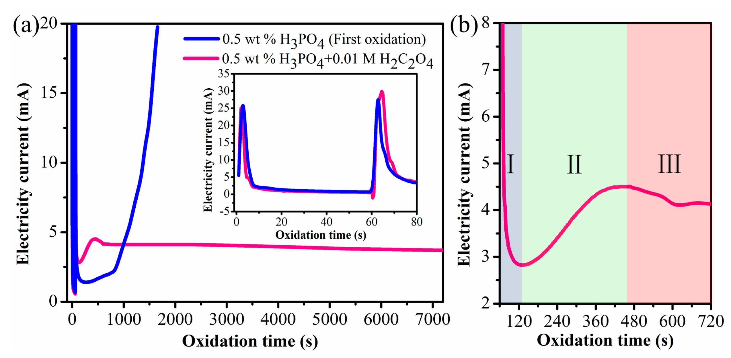
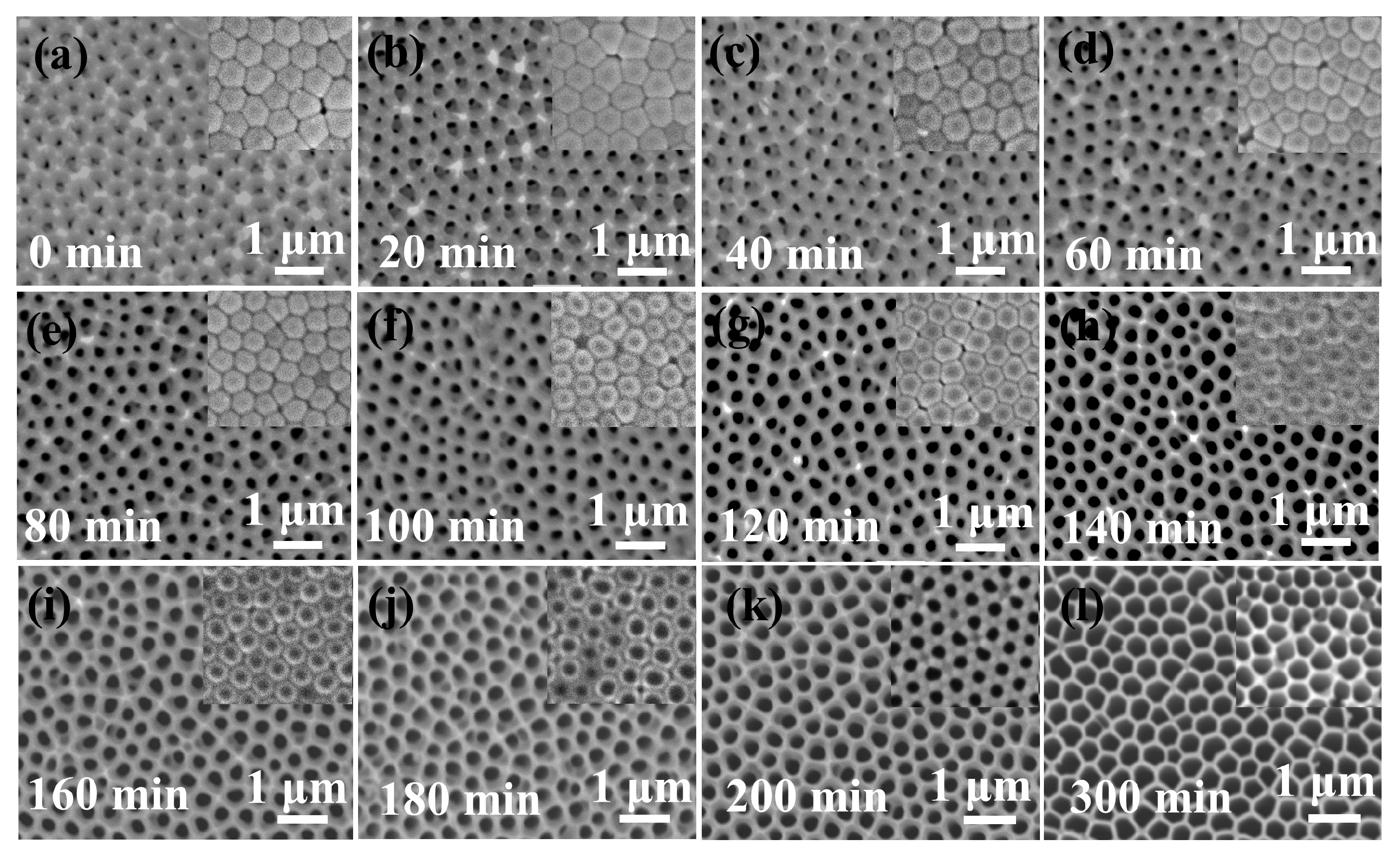
3.1. Using a Mixed Acid of Phosphoric Acid and Oxalic Acid as the Electrolyte

The variation in the current with the oxidation time in different electrolytes is shown in Figure 2. First, the inset in Figure 2a displays the high stability of the two-step voltage process at oxidation times < 80 s, which plays an important role in the preparation of the AAO template. However, in the electrolyte consisting of phosphoric acid only, the current instantaneously rose at 800 s (shown as the blue curve in Figure 2a), and combustion occurred on the surface of the aluminum foil. The difference is that the current tended to gradually stabilize in the mixed acid electrolyte (0.5 wt % H3PO4 and 0.01 M H2C2O4), which is shown as the pink curve in Figure 2a. This phenomenon indicates that the mixed acid electrolyte effectively resolves the problem of burning of the oxide film under high voltage. The reason can be illustrated as follows: in the mixed acid electrolyte, the generated Al3+ prefers to coordinate with acid anions (C2O42−) to form a complex, which could reduce the migration of ions and inhibit the anodization process, thereby avoiding “burning” of the aluminum foil.
Additionally, the formation mechanism of the AAO film can be explained from the curve of current–time variation [30], which is shown in Figure 2b. The curve is mainly divided into three stages: (1) The sudden appearance of the applied electric field will generate a pulse current signal, and then an oxide layer (high resistance) is formed on the surface of the aluminum foil, which hinders the transmission of charged ions in the solution so that the current drops instantaneously from more than 20 mA to a minimum of 2.8 mA. (2) When the oxidation time reaches 130 s, the current starts to increase. In this stage, the oxide layer gradually becomes thicker, the volume expansion causes cracks, and then the solution penetrates the crack. A field-assisted dissolution reaction occurs under the action of the electric field. The pores are initially nucleated, and the current gradually increases and reaches a maximum (4.5 mA at 450 s). (3) Subsequently, the current tends to stabilize at an oxidation time of 720 s after adjustment. At this moment, the rates of both increasing and decreasing current have reached a dynamic balance.

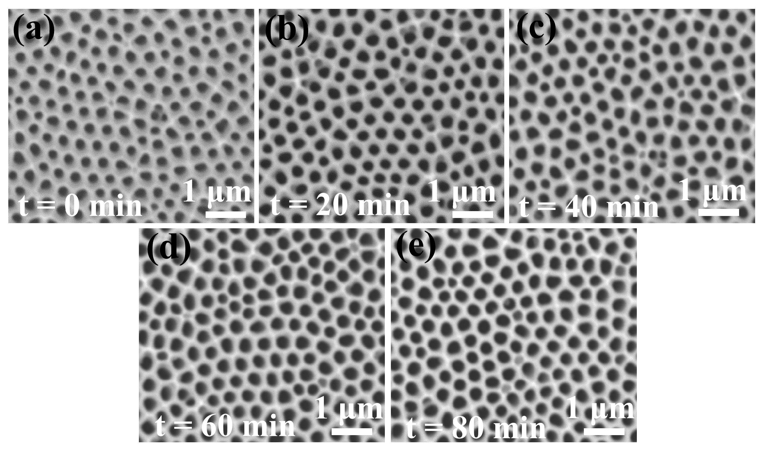
3.2. Using PMMA as Filler

For comparison, the AAO template was also prepared without using PMMA, and parameters such as the interpore distance (Dc), thickness, and pore diameter were studied. First, the interpore distance is mainly determined by the oxidation voltage [31]:
Dc=λc·U
where the proportionality constant λc is approximately 2.5 nm·V−1. Here, the theoretical value of Dc is approximately 487 nm at U = 195 V, which is very close to the value (496 ± 10 nm) measured from the SEM image, as shown in Figure 3a.
Second, the thickness of the AAO is determined by the oxidation time. Figure 3b–e shows the cross-sectional image of the template after oxidation for 1 h, 2 h, 3 h and 4 h. The nanopore walls are smooth, straight and parallel to each other. Additionally, the thickness increased with increasing oxidation time. Figure 3f also displays a linear relation between the film thickness and the oxidation time. The growth rate was approximately 6.3 μm/h, which is influenced by the second anodization time.
Last, the pore diameter was determined by the etching time. The impact of the pore-widening duration on the diameter of the pores is depicted in Figure 4. The pore diameter gradually increased with increasing etching time. Figure 5 shows the linear relation between the pore diameter and etching time, and the etching rate was calculated to be approximately 1.06 nm/min. When the etching time reached 300 min, the pore diameter was increased to 400 nm, and the pores show a hexagonal morphology. Furthermore, the morphology of the barrier layer is also given in the upper right corner of Figure 4, indicating that obtaining the double-pass AAO required an etching time of ≥200 min. However, the pore diameter was close to 300 nm after etching for this time. Therefore, based on only the above steps (method), there was a limitation in the pore diameter of the double-pass AAO film, which would limit the application of the template.
Therefore, the PMMA colloid that did not react with acids but dissolved in acetone was chosen as the reagent to fill the pores in this work. A schematic diagram is shown in Figure 6. In brief, the PMMA colloid was filled into the single-pass AAO, and then the barrier layer was removed in a phosphoric acid solution. Finally, the double-pass AAO was obtained after removal of the PMMA colloid in acetone. Figure 7a,b shows that the dried PMMA has filled into the pore, as seen in the SEM images of the removed AAO area and the cross-sectional view. Figure 7c–f shows the morphology of the AAO template and barrier layer after etching the PMMA/AAO composite for different times. Notably, the barrier layer was completely removed after etching for 8 h.
After removal of the barrier layer, the pore diameter can be further increased by etching in solution. Figure 8 shows SEM images of the AAO film (after 8 h of barrier layer removal) after etching for different times (0 min, 20 min, 40 min, 60 min and 80 min). The variation in pore diameter as a function of etching time is shown in Figure 9. It is clearly demonstrated that the pore diameter is dependent on the etching time. The pore diameter increased from 230 to 310 nm after 80 min of etching. The average etching rate is calculated to be 1 nm/min, which is basically consistent with the comparison experiment. The pore diameter can be controlled in the range of 230–400 nm by using the PMMA colloid, which is wider than the pore diameter of AAO without using PMMA (300–400 nm). Therefore, using a PMMA colloid can effectively avoid pore contact with the solution and achieve a wide pore diameter range in the double-pass AAO.

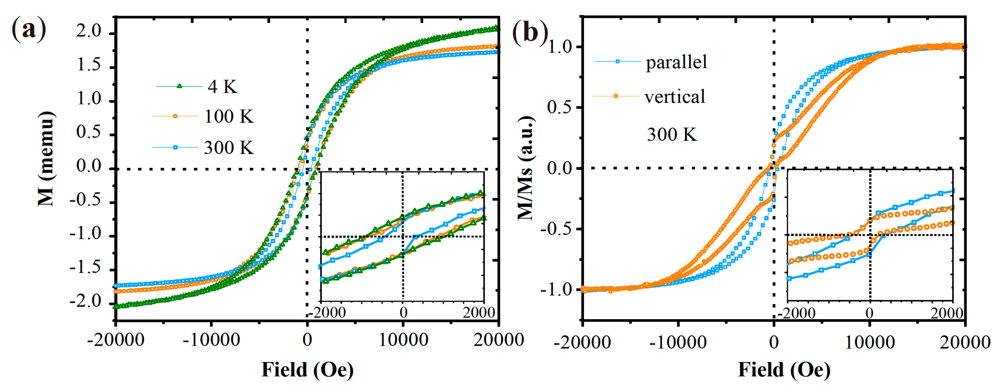
3.3. Characterization of CFO Nanowires

Subsequently, the CFO nanowires was fabricated into the above made double-pass AAO template with a 255 nm pore diameter by the electrochemical deposition method. The morphologies of CFO nanowires after annealing at 720 °C for 10 h were observed by SEM. On the left of Figure 10a shows a represent SEM image of the AAO template with CFO nanowires, proving that the nanowires grow closely along the template channels, and the nanowire diameter was approximately equal to the template pore diameter. A uniform length (5 μm) and straight nanowire arrays were obtained after the AAO template was dissolved away, which is shown on the right. EDS spectrum (Figure 10b) quantitative analysis of CFO nanowires indicates an approximately 1:2 atomic ratios of Co:Fe, inferring a CoFe2O4 compositions for the nanowire prepared under these experimental conditions.
Figure 10c shows the XRD pattern of CFO nanowires within the AAO template. Strong diffraction peaks of crystalline Al2O3 could be observed due to the oxidized of AAO at high annealing temperature. Although for the noise signal, the diffraction peaks of CFO could also be indexed according to the PDF#22-1086 standard for CFO. The result indicates that the obtained CFO nanowires had no preferred crystallite orientation. Additionally, a diffraction peak of Fe (100) could also be observed in the XRD pattern, which declared incomplete oxidation for the CoFe2 alloy nanowire with a 250 nm diameter even for 10 h.
The static magnetic properties of CFO nanowires in AAO templates were studied by using the hysteresis loops as shown in Figure 10. The representative hysteresis curves of the CFO nanowires at three temperatures (4 K, 100 K, and 300 K) are displayed. It can be obtained that the coercivity (HC) and saturation magnetization (Ms) increased by 118% and 22% respectively, with the decrease of temperature from 300 to 4 K. The static magnetic properties of CFO nanowires in AAO templates were studied by using the hysteresis loops as shown in Figure 11. The representative hysteresis curves of the CFO nanowires at three temperatures (4 K, 100 K, and 300 K) are displayed. One of the remarkable features in Figure 11a is that the magnetization did not saturate at low temperature, especially at 4 K. It could be attributed to the disordered spins at the surface of nanoparticles that are difficult to align along the field direction causing an unsaturated magnetization in these particles. The inset of the figures shows a magnified region around the origin to make the coercivity more visible at various temperatures. It can be obtained that the coercivity (HC) and saturation magnetization (Ms) increased by 118% and 22% respectively, with the decrease of temperature from 300 K to 4 K. The thermal fluctuation affected the blocked moment across the anisotropy barrier, which is a reason for the increase in HC with a decrease in temperature. The Kneller’s law as follows in Equation (2) can well explain the relationship between coercivity and temperature (<TB, TB is the superparamagnetic blocking temperature of the nanoparticles) of the magnetic nanostructure with anisotropy [32].
H C = H 0 ( 1 T / T B ) 1 2
Here, H 0 is the coercivity at T = 0 K. It is obtained that the HC was increasing with the decrease of temperature. Similarly, the relation between saturation magnetization and temperature can be explained by the Bloch’s law and the modified Bloch’s law [33] as:
M s = M 0 ( 1 T / T 0 ) α
Here, M 0 is the magnetization at T = 0 K, and T 0   is the temperature when the Ms is zero. ( 1 / T 0 ) α is called the Bloch’s constant (B) that depends upon the structure of the material. For the nanoparticles, the Bloch exponent α is large than 3/2 [34]. Therefore, the Ms also increases with a decrease in temperature of the sample.
The hysteresis loop of the CFO nanowire arrays with the applied field parallel and vertical to the longitudinal nanowires were also given in Figure 11b. It is shown that their hysteresis loops were different, which means that the CFO nanowires fabricated show an anisotropic behavior. This behavior was mainly due to the larger shape anisotropy of the nanowires. It is interesting to find that the hysteresis curves vertical to the longitudinal nanowires demonstrated an obvious wasp-waisted hysteresis loop. It is worth to note that the hysteresis curve exhibited obvious constricted M–H loops characterized by a small coercivity at low fields whereas at higher field these M–H loops were open at both ends. If there were further raising of the field, closing of loops and magnetization saturation could be observed. The reason for this type of hysteresis loop is generally observed in bimagnetic exchange spring systems consisting of two chemically different magnetic phases; one soft phase and the other one hard phase [35,36,37]. In this work, the hard phase of CFO and soft phase of Fe coexisted in the nanowires, which was confirmed from the XRD results. As a result, a wasp-waisted structure formed in the low field. Furthermore, this phenomenon was more obvious in the vertical direction than the parallel direction, which might be for its high shape anisotropy.

4. Conclusions

A double-pass AAO template was prepared by a two-step oxidation method using a mixed acid of phosphoric acid and oxalic acid as the electrolyte and PMMA as the filler. The combustion of aluminum foil at a high voltage was effectively resolved by using this mixed acid. Additionally, the range of pore diameters was obviously increased to 230–400 nm by using PMMA as the filler, which can prevent contact between the pores and the solution when removing the barrier layer. Subsequently, CFO ferrite nanowire arrays were successfully fabricated into the double-pass AAO template, and show an anisotropic feature of magnetic properties.

Author Contributions

Investigation, W.C. and D.H.; writing—original draft preparation, W.C.; writing—review and editing, H.Z. and Y.Z; data curation, Q.W. and L.Z.; supervision, H.Z., P.Z. and Y.Z.; project administration, H.Z., P.Z. and Y.Z. All authors have read and agreed to the published version of the manuscript.

Funding

This research was funded by the National Natural Science Foundation of China (Grant No. 51702075, 51771176), National Key Research and Development Project (Grant No. 2019YFF0217205).

Conflicts of Interest

The authors declare no conflict of interest. The funders had no role in the design of the study; in the collection, analyses, or interpretation of data; in the writing of the manuscript; or in the decision to publish the results.

References

  1. Gudiksen, M.S.; Lauhon, L.J.; Wang, J.; Smith, D.C.; Lieber, C.M. Growth of nanowire superlattice structures for nanoscale photonics and electronics. Nature 2002, 415, 617–620. [Google Scholar] [CrossRef] [PubMed]
  2. Wang, Z.W.; Cai, J.Q.; Wu, Y.Z.; Wang, H.J.; Xu, X.L. Ordered silicon nanorod arrays with controllable geometry and robust hydrophobicity. Chin. Phys. B 2014, 24, 017802. [Google Scholar] [CrossRef]
  3. Petrov, V.M.; Bichurin, M.I.; Srinivasan, G. Electromechanical resonance in ferrite-piezoelectric nanopillars, nanowires, nanobilayers, and magnetoelectric interactions. J. Appl. Phys. 2010, 107, 073908.1–073908.6. [Google Scholar] [CrossRef]
  4. Zheng, H.; Han, M.G.; Deng, L.J. Fabrication of CoFe2O4 ferrite nanowire arrays in porous silicon template and their local magnetic properties. Chin. Phys. B 2016, 25, 026201. [Google Scholar] [CrossRef]
  5. Pervaiz, E.; Gul, I.H.; Anwar, H. Hydrothermal synthesis and characterization of CoFe2O4 nanoparticles and nanorods. J. Supercond. Novel Magn. 2013, 26, 44193. [Google Scholar] [CrossRef]
  6. Zhen, L.; He, K.; Xu, C.Y.; Shao, W.Z. Synthesis and characterization of single-crystalline MnFe2O4 nanorods via a surfactant-free hydrothermal route. J. Magn. Magn. Mater. 2008, 320, 2672–2675. [Google Scholar] [CrossRef]
  7. Zhang, D.E.; Zhang, X.J.; Ni, X.M.; Zheng, H.G.; Yang, D.D. Synthesis and characterization of NiFe2O4 magnetic nanorods via a PEG-assisted route. J. Magn. Magn. Mater. 2005, 292, 79–82. [Google Scholar] [CrossRef]
  8. Mehri, A.; Ebrahimi, S.A.S.; Masoudpanah, S.M. Synthesis and characterization of high aspect ratio NiFe2O4 nanowire. J. Anal. Appl. Pyrolysis. 2014, 110, 235–238. [Google Scholar] [CrossRef]
  9. Pirouzfar, A.; Ebrahimi, S.A.S. Optimization of sol-gel synthesis of CoFe2O4 nanowires using template assisted vacuum suction method. J. Magn. Magn. Mater. 2014, 370, 1–5. [Google Scholar] [CrossRef]
  10. Ebrahimi, F.; Ashrafizadeh, F.; Bakhshi, S.R. Tuning the magnetic properties of high aligned strontium ferrite nanowires formed in alumna template. J. Alloys Compd. 2016, 656, 237–244. [Google Scholar] [CrossRef]
  11. Hua, Z.H.; Chen, R.S.; Li, C.L.; Yang, S.G.; Lu, M.; Gu, B.X.; Du, Y.W. CoFe2O4 nanowire arrays prepared by template electrodeposition method and further oxidization. J. Alloys Compd. 2007, 427, 199–203. [Google Scholar] [CrossRef]
  12. Xu, Y.; Xue, D.S.; Gao, D.Q.; Fu, J.L.; Fan, X.L.; Guo, D.W.; Gao, B.; Sui, W.B. Ordered CoFe2O4 nanowire arrays with preferred crystal orientation and magnetic anisotropy. Electrochim. Acta 2009, 54, 5684–5687. [Google Scholar] [CrossRef]
  13. Gao, D.; Shi, Z.; Xu, Y.; Zhang, J.; Yang, G.J.; Zhang, J.L.; Wang, X.H.; Xue, D.S. Synthesis, magnetic anisotropy and optical properties of preferred oriented zinc ferrite nanowire arrays. Nanoscale Res. Lett. 2010, 5, 1289–1294. [Google Scholar] [CrossRef] [PubMed] [Green Version]
  14. Zheng, H.; Han, M.; Zheng, L.; Zheng, L.; Zheng, P.; Wu, Q.; Deng, L.J.; Qin, H.B. Preparing magnetic yttrium iron garnet nanodot arrays by ultrathin anodic alumina template on silicon substrate. Appl. Phys. Lett. 2015, 34, 064201. [Google Scholar] [CrossRef]
  15. Xu, Z.; Zheng, H.; Han, M. Preparation and morphology magnetic properties of yttrium iron garnet nanodot arrays on Gd3Ga5O12 substrate. Chem. Phys. Lett. 2017, 680, 90–93. [Google Scholar] [CrossRef]
  16. Bornemann, S.; Minar, J.; Braun, J.; Ködderitzsch, D.; Ebert, H. Ab-initio description of the magnetic shape anisotropy due to the Breit interaction. Solid State Commun. 2010, 152, 85–89. [Google Scholar] [CrossRef] [Green Version]
  17. Atchudan, R.; Perumal, S.; Yong, R.L. Highly graphitic carbon nanosheets synthesized over tailored mesoporous molecular sieves using acetylene by chemical vapor deposition method. RSC Adv. 2015, 5, 93364–93373. [Google Scholar] [CrossRef]
  18. Datta, A.; Sangle, A.; Hardingham, N.; Cooper, C.; Kraan, M.; Ritchie, D.; Narayan, V.; Kar-Narayan, S. Structure and Thermoelectric Properties of Bi2−xSbxTe3 Nanowires Grown in Flexible Nanoporous Polycarbonate Templates. Materials 2017, 10, 553. [Google Scholar] [CrossRef] [Green Version]
  19. Zheng, H.; Han, M.; Zheng, L.; Zheng, L.; Zheng, P.; Wu, Q.; Deng, L.J.; Qin, H.B. Porous silicon templates prepared by Cu-assisted chemical etching. Mater. Lett. 2014, 118, 146–149. [Google Scholar] [CrossRef]
  20. Manzano, C.V.; Bürki, G.; Pethö, L.; Michler, J.; Philippe, L. Determining the diffusion mechanism for high aspect ratio ZnO nanowires electrodeposited into anodic aluminum oxide. J. Mater. Chem. 2017, 5, 1706–1713. [Google Scholar] [CrossRef]
  21. Masuda, H.; Fukuda, K. Ordered metal nanohole arrays made by a two-step replication of honeycomb structures of anodic alumina. Science 1995, 268, 1466–1468. [Google Scholar] [CrossRef]
  22. Chahrour, K.M.; Ahmed, N.M.; Hashim, M.R.; Elfadill, N.G.; Ahmad, M.A.; Bououdina, M. Influence of wet etching time cycles on morphology features of thin porous Anodic Aluminum oxide (AAO) template for nanostructure’s synthesis. J. Phys. Chem. Solids 2015, 87, 1–8. [Google Scholar] [CrossRef]
  23. Belwalkar, A.; Grasing, E.; Geertruyden, W.V.; Huang, Z.; Misiolek, W.Z. Effect of processing parameters on pore structure and thickness of anodic aluminum oxide (AAO) tubular membranes. J. Membr. Sci. 2008, 319, 192–198. [Google Scholar] [CrossRef] [Green Version]
  24. Sulka, G.D.; Parkota, K.G. Temperature influence on well-ordered nanopore structures grown by anodization of aluminium in sulphuric acid. Electrochim. Acta 2007, 52, 1880–1888. [Google Scholar] [CrossRef]
  25. Sulka, G.D.; Parkota, K.G. Anodizing potential influence on well-ordered nanostructures formed by anodisation of aluminium in sulphuric acid. Thin Solid Films 2006, 515, 338–345. [Google Scholar] [CrossRef]
  26. Schneider, J.J.; Engstler, J.; Budna, K.P.; Christian, T.; Steffen, F. Freestanding, highly flexible, large area, nanoporous alumina membranes with complete through-hole pore morphology. Eur. J. Inorg. Chem. 2005, 2005, 2352–2359. [Google Scholar] [CrossRef]
  27. Li, Y.; Ling, Z.Y.; Wang, J.C.; Chen, S.S.; Hu, X.; He, X.H. Fabrication of porous alumina templates with a large-scale tunable interpore distance in a H2C2O4-C2H5OH-H2O solution. Chin. Sci. Bull. 2008, 53, 1608–1612. [Google Scholar] [CrossRef] [Green Version]
  28. Martín, J.; Manzano, C.V.; Martín-González, M. In-depth study of self-ordered porous alumina in the 140–400 nm pore diameter range. Microporous Mesoporous Mater. 2012, 151, 311–316. [Google Scholar] [CrossRef]
  29. Chen, W.; Wu, J.S.; Xia, X.H. Porous Anodic Alumina with Continuously Manipulated Pore/Cell Size. ACS Nano 2008, 2, 959–965. [Google Scholar] [CrossRef]
  30. Ding, G.Q.; Zheng, M.J.; Xu, W.L.; Shen, W.Z. Fabrication of controllable free-standing ultrathin porous alumina membranes. Nanotechnology 2005, 16, 1285–1289. [Google Scholar] [CrossRef]
  31. Su, Z.; Hähner, G.; Zhou, W. Investigation of the pore formation in anodic aluminum oxide. J. Mater. Chem. 2005, 18, 5787–5795. [Google Scholar] [CrossRef]
  32. Batlle, X.; Garcia, D.M.M.; Tejada, J.; Gornert, P.; Sinn, E. Magnetic study of M-type doped barium ferrite nanocrystalline powders. J. Appl. Phys. 1993, 74, 3333. [Google Scholar] [CrossRef] [Green Version]
  33. Hendriksen, P.V.; Linderoth, S.; Lindgard, P.A. Finite-size modifications of the magnetic properties of clusters. Phys. Rev. B 1993, 48, 7259–7273. [Google Scholar] [CrossRef] [PubMed] [Green Version]
  34. Linderoth, S.; Balcells, L.; Labarta, A.; Tejada, J.; Hendriksen, P.V.; Sethi, S.A. Magnetization and Mossbauer studies of ultrafine Fe-C particles. J. Magn. Magn. Mater. 1993, 124, 269–276. [Google Scholar] [CrossRef]
  35. Otani, O.; Miyajima, H.; Chikazumi, H.; Hirosawa, S.; Sagawa, M. Magnetization processes in Nd-Fe-B permanent magnets. J. Magn. Magn. Mater. 1986, 60, 168–170. [Google Scholar] [CrossRef]
  36. Chithra, M.; Anumol, C.N.; Sahu, B.; Sahoo, S.C. Exchange spring like magnetic behavior in cobalt ferrite nanoparticles. J. Magn. Magn. Mater. 2016, 401, 1–8. [Google Scholar] [CrossRef]
  37. Li, X.; Guo, F.; Wang, S.Y.; Wang, X.; Xu, X.L.; Gao, J.; Liu, W.F. Template-free synthesis of Nd0.1Bi0.9FeO3 nanotubes with large inner diameter and wasp-waisted hysteresis loop. Appl. Phys. Lett. 2015, 107, 062903. [Google Scholar] [CrossRef] [Green Version]
Figure 1. Schematic diagram of synthesis mechanism of the CFO nanowire.
Crystals 10 00331 g001
Figure 2. (a) Current–time variation during anodization in an electrolyte consisting of 0.5 wt % H3PO4 and 0. 5 wt % H3PO4 with the addition of 0.01 M H2C2O4., the illustration of (a) is current–time variation of two-step voltage process; (b) Current variation from 120 s to 720 s.
Crystals 10 00331 g002
Figure 3. (a) Top view of the anodized alumina oxide (AAO) film; (b–e) cross-section of AAO film grown at different anodizing times (1 h, 2 h, 3 h, 4 h); and (f) curve correlating AAO film thickness with anodizing time.
Crystals 10 00331 g003
Figure 4. SEM images of the AAO film under different etching times. (a–l) SEM images of the PMMA/AAO composite film after different etching times.
Crystals 10 00331 g004
Figure 5. Curve correlating the mean pore diameter with etching time.
Crystals 10 00331 g005
Figure 6. Schematic diagram of the barrier layer removal by using the PMMA colloid.
Crystals 10 00331 g006
Figure 7. (a) Top view of the PMMA/AAO composite film; (b) cross-sectional view of the PMMA/AAO composite film; and (c–h) SEM images of the PMMA/AAO composite film after different etching times.
Crystals 10 00331 g007
Figure 8. SEM images of the AAO template after etching for different times: (a) 0 min; (b) 20 min; (c) 40 min; (d) 60 min; and (e) 80 min.
Crystals 10 00331 g008
Figure 9. Curve correlating the mean pore diameter with etching time.
Crystals 10 00331 g009
Figure 10. Morphology and crystal structure of the prepared CFO nanowires, (a) SEM images; (b) EDS spectrum; and (c) XRD pattern.
Crystals 10 00331 g010
Figure 11. Magnetism of the obtained CFO nanowires, (a) hysteresis loops along the parallel direction at 4 K, 100 K, and 300 K and (b) hysteresis loops along the parallel and vertical direction at 300 K. The insets show the magnified region.
Crystals 10 00331 g011
Table 1. The experimental parameters of two-step anodic oxidation.
-First AnodizationOxide RemovalSecond Anodization
Solution0.5 wt % H3PO4 +
0.01 M C2H2O4
6 wt % H3PO4 +
1.5 wt % H2CrO4
0.5 wt % H3PO4 +
0.01 M C2H2O4
Temperature5 °C60 °C5 °C
Time2 h2 h-

