Article

The Effect of Ion Irradiation Density on the Defect of Graphene: A Molecular Dynamics Study

1
Key Laboratory for Wide Band Gap Semiconductor Materials and Devices of Education, The School of Microelectronics, Xidian University, Xi’an 710071, China
2
School of Microelectronics, Northwestern Polytechnical University, Xi’an 710072, China
*
Author to whom correspondence should be addressed.
Crystals 2020, 10(3), 158; https://doi.org/10.3390/cryst10030158
Submission received: 5 February 2020 / Revised: 25 February 2020 / Accepted: 28 February 2020 / Published: 1 March 2020
(This article belongs to the Special Issue 2D Materials: From Structures to Functions)

Abstract

:
This paper analyzes graphene irradiation effects using a molecular dynamic simulation software, large-scale atomic / molecular massively parallel simulator (LAMMPS). We propose a hypothesis for the effective range of incident ions based on simulation results of irradiation effects that were found using a suspended single-layer graphene. This explains the influence mechanism of irradiation density on the degree of material defects. This paper does key research on how copper substrate influences a single- and bi-layer graphene. The results show that for a single-layer graphene (SLG) the substrate increases the effective range of the incident ions. Within a certain range of the irradiation density, the substrate enhances the defect production on graphene in low-energy irradiation (<5 keV). However, due to the shielding effect of the substrate, the overall trend of graphene damage will be reduced. For the bi-layer graphene (BLG), the effect of the indirect action range is more obvious than that of the direct-action range. In the case of low irradiation density, the knock-on atoms of BLG are much less than suspended SLG.

1. Introduction

Graphene is a two-dimensional (2D) atomic crystal formed by a single layer of carbon atoms and arranged in a hexagonal honeycomb structure with sp2 hybrid orbitals [1]. The spacing between two carbon atoms connected by chemical bonds is about 1.42 Å. Graphene has great conductivity materials and low resistivity at room temperature—only 10−6 Ω·cm—which results from the special 2D structure [2]. Therefore, it is expected to have extremely broad application prospects in the electronics industry due to its low resistivity and high electron mobility [3]. However, the property of zero-bandgap semiconductors limits the utilization of graphene [2,4]. In order to maximize the practical value of graphene, precisely affecting electronic properties of materials through changing atomic structure is required. The introduction of defects in the crystal lattice can transform the semi-metal properties without a forbidden band and band-tunable semiconductor properties [5,6,7]. Based on different radiation sources, the command of the graphene surface state through irradiation ions could precisely adjust the atomic structure level, control the doping and defect generation of materials, and efficiently improve electrical properties, avoiding the disordered doping and sample contamination problem caused by chemical vapor deposition (CVD) [8,9,10,11,12].
As a technique for controlling the characteristics of graphene, ion irradiation has been studied for a long time. It is noteworthy that researchers have made progress in the study of irradiation effect of graphene, especially single-layer suspended graphene (SLG) [13,14,15,16,17,18]. Although special experimental phenomena observed in bi-layer graphene (BLG) were presented in previous papers [19,20], little literature is available on BLG. Moreover, researchers are now concerned with the effects of the energy of irradiated ions on graphene [15,16,17,18,19,20,21,22]. Therefore, the present work deals with the irradiation effect of both SLG and BLG from the perspective of irradiation density using the molecular dynamics (MD) simulation software large-scale atomic / molecular massively parallel simulator (LAMMPS). Herein, carbon atoms were selected as the irradiation source.

2. Materials and Methods

This work used a classical MD simulation to simulate the ion-solid interaction process. MD is a simulation method that used the computer to study the physical motion of atoms and molecules. It numerically solves a system’s Newton equation, as it contains interacting particles that determine the trajectories of atoms and molecules. Moreover, it is expressed in the study of carbon nanostructures [23,24,25]. The Adaptive Intermolecular Reactive Empirical Bond Order (AIREBO) potential function [26] is used to describe the carbon–carbon interaction in graphene. The Ziegler–Biersack–Littmark (ZBL) [27] potential function is used to describe the interaction between incident ions and graphene carbon atoms. The advantage of the ZBL potential function is that some dynamic processes that exist in the covalently bonded crystal structure in simulation are fully considered, such as the formation and breaking of chemical bonds. Meanwhile, the interaction between the graphene and the substrate is assumed to be van der Waals (vdW) type and is described by the Lennard–Jones (LJ) potential function [28,29]. The effect of irradiation particle density on damage is investigated by changing the distance between the incident ions.
A single-layer graphene includes 963 C atoms with an area of 5 nm × 5 nm. The ion incident area is an area within the radius of the graphene center point of 2.5 nm. The radiation dose of injection carbon ions is 25, arranged according to the matrix attribute of 5 × 5. They were launched all together with the same velocity at a normal incidence against graphene. The thickness of the copper substrate is 10 nm. Crystallographic orientation of the substrate is (111) and the specific atomic configuration of graphene is shown in Figure 1. Moreover, we apply periodic boundary conditions in two dimensions to treat the boundary of the system as a continuous edge. In the MD simulation, the Berendsen temperature control technique is employed at the four borders of graphene and copper substrate in the x- and y- directions. In addition, the simulation system adopts the microcanonical ensemble (NVE) during the entire simulation process. The number of particles, the volume of materials, and the total energy retention are constant in the system. During the simulation, the system first heats up to room temperature to 300 K. After it relaxes to 50 ps at this temperature, the incident ion is introduced into the cell. When the temperature of the system is less than 500 K and the structure of the system no longer changes significantly, the simulation ends. After the simulation, Visual Molecular Dynamics (VMD) software is utilized to visualize the results.

3. Results and Discussion

The results of the molecular dynamics simulation of irradiation effect usually present as the defects on the surface of graphene. The main defects include knock-on carbon atoms, single vacancy defects (SV), double vacancy defects (DV), and complex defects (including carbon chains) [30,31,32]. In this paper, the carbon atoms knocked out of graphene refer to the carbon atoms displaced more than 5 Å from their initial position after simulation. In the absence of sufficient displacement, it is possible for knock-on carbon atoms to reform sp2 hybridization with other carbon atoms near the surface of materials and the previously formed defects eventually disappear as the surface temperature gradually returns to room temperature.

3.1. Suspended Single-Layer Graphene

Firstly, the relationship between the irradiation defect and the irradiation density of graphene was studied. As Figure 2 shows, the number of knock-on atoms of suspended SLG varied with its respective incident ion distance. Comparing the irradiation effect of different ion energies, we can see that the larger the ion energy, the lesser the number of knock-on atoms. According to the simulation results of the suspension in reference [9,17,33], an increase of irradiation energy leads to an initial rise in the number of knock-on atoms, which is followed by a subsequent drop. The initial increment with ion energy can easily be understood and explained by the fact that low-energy ions simply cannot displace target atoms, while they later decrease at high energies, which is related to a drop in the cross section for defect production [9]. Based on the results of our previous work [33], the turning point is about 1 keV.
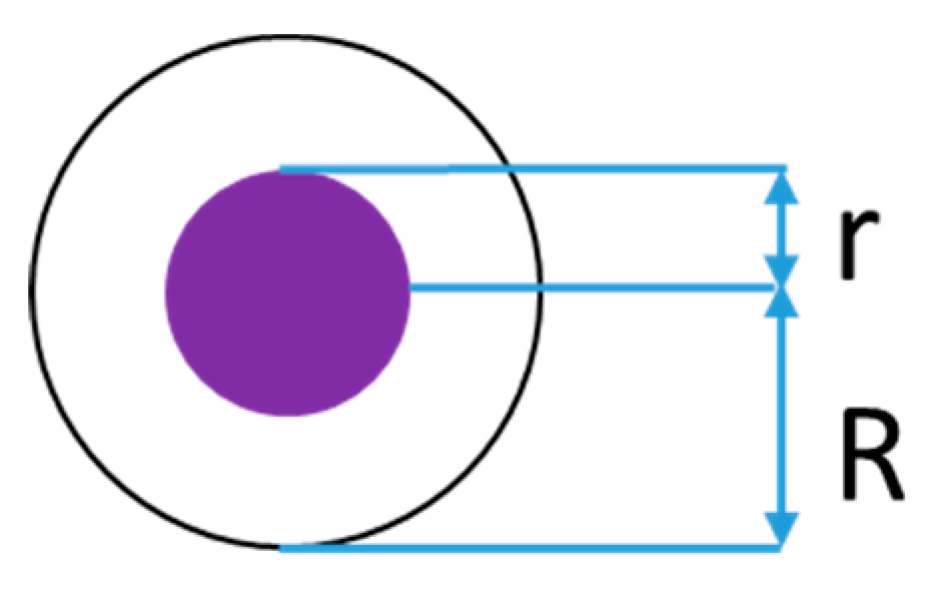
At the same irradiation intensity, with the increasing distance between incident ions, the trend of the number knock-on atoms is described as three stages: rising first, rapidly decreasing, and stabilizing. The hypothesis of an effective range of incident ions is proposed first in this paper to analyze the reason for this trend. It is assumed that each incident ion has an effective range that is divided into two parts, as shown in Figure 3. Within the shorter radius, r, a single incident ion with enough energy can knockout all carbon atoms in this range, which can be called the direct-action range. (R – r) represents an indirect action range that requires multiple incident ions to knockout carbon atoms. In consonance with this hypothesis, the relationship between the ion action range and the incident density displayed in Figure 4 can be classified into three stages. First, for a sufficiently large incident density, the direct-action range of each incident ion overlaps. Next, with the incident density decreasing the overlap area decreases, the sum of the direct-action range increases and the number of knock-on atoms increases as well. After the maximum direct range, the mutually overlapping R radius becomes smaller. The indirect action range decreases and the number of knock-on atoms rapidly decreases. Finally, when the action range of each ion no longer overlaps, the number of defects tends to be stable.
When the incident ion distance is greater than or equal to 2R, the direct-action range generates all knock-on atoms, and its number remains stable as the distance continues to increase. Thus, the value of R is equal to half of the distance when knock-on atoms trends to stabilize. The calculation results are presented in Table 1 and a broken line in Figure 2 indicates the position of (R + r). It can be observed that this position is where the number of knock-on atoms rapidly decreases from the maximum value, which is in accordance with the assumed result.
This hypothesis originates from two major sources. One is the theoretical model proposed in 2010 to explain the Raman spectrum after the irradiation of graphene [14]. The inner ring is called the structural damage zone, implying that the graphene lattice structure is completely destroyed. The outer ring, however, is called the activation region, which means that the lattice structure of graphene is affected. This is in agreement with Figure 3. The other is based on molecular dynamics. Knocked out atoms indicate that the external force for graphene atoms is greater than the magnitude of the carbon–carbon bond energy. According to the law of motion, the external force of the atom is correlated with the distance. The farther the distance between graphene atoms and incident particles, the lower the force exerted on atoms. This article arranges the relationship between the force and the distance into three stages as a simplified model: a single ion generating a sufficient force to knock an atom out of the surface, multiple ions acting on one atom out of the surface, and the distance from which atoms cannot be knocked out.
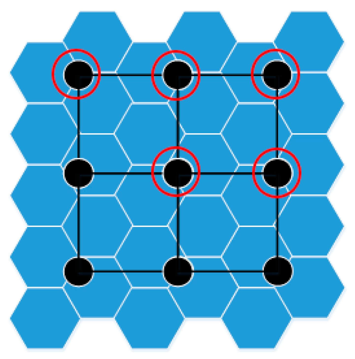
In order to further verify the hypothesis of effective range of incident ions, the results of graphene irradiation are simulated via drawing (Figure 5) with conditions of incident ion distance of 4.0 Å, irradiation energy of 4.41 keV, and an irradiation dose of 9. According to the calculation results in Table 1, the direct-action radius is 0.6 Å, and the indirect action radius is 1.8 Å, which is less than half of the ion distance (2 Å). Therefore, only the direct-action range is effective in irradiation. As shown in Figure 5, the number of graphene atoms covered by the direct-action range is equal to five, which is consistent with the results of computer simulation, further proving the rationality of the hypothesis.

3.2. Single-Layer Graphene on Copper Substrate

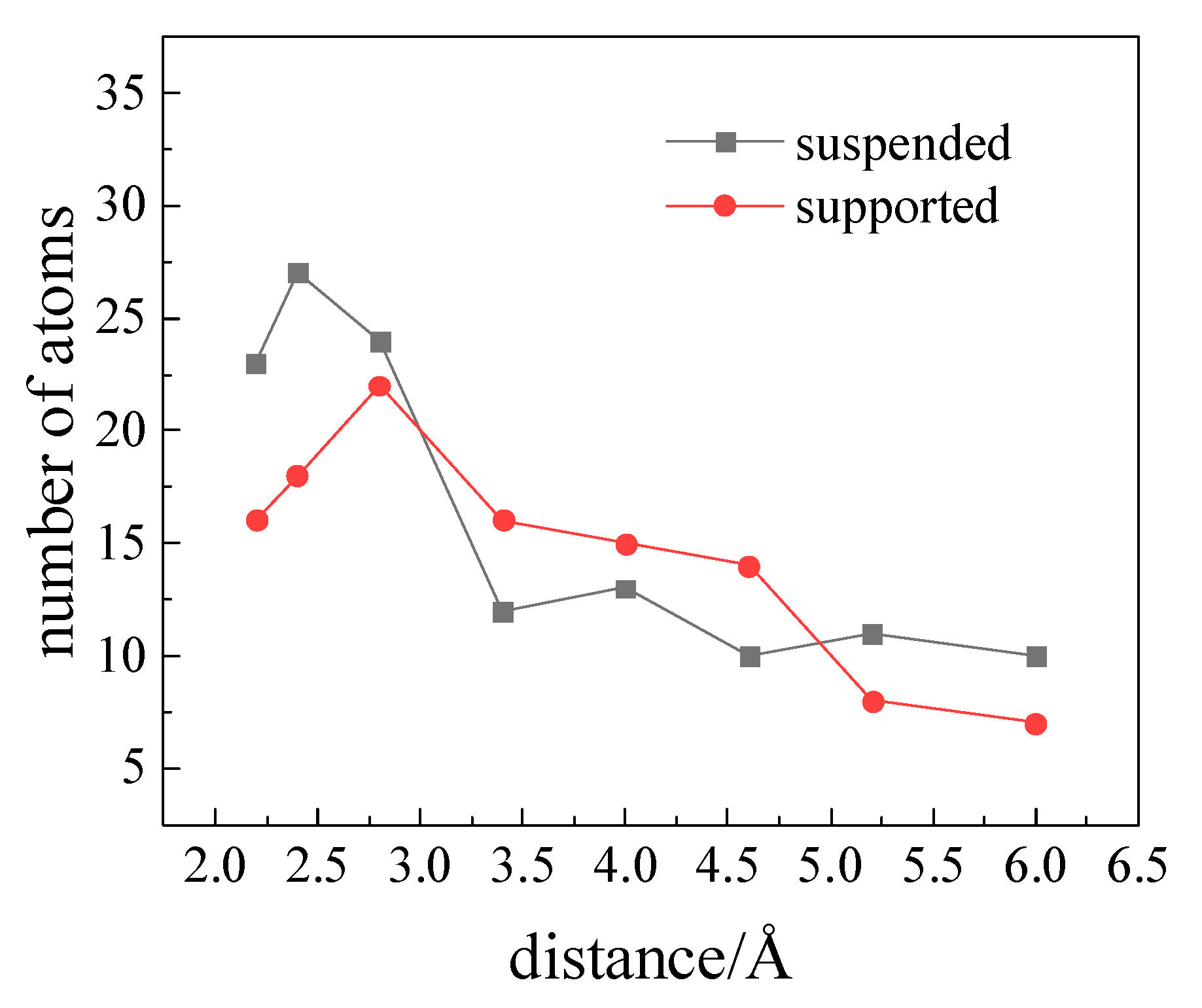
Next, the effect of the substrate on the irradiation of SLG is discussed. As shown in Figure 6, with the increasing incident ion spacing, the number of knock-on carbon atoms on the supported SLG shows a trend of initially increasing, then decreasing, and finally stabilizing, which is identical to the trend of the results when suspended. When the distance between the incident ions is short enough, the range of the direct effective interaction radius between the incident ions covers each other. Therefore, with the increase of the distance between the ions, the number of knock-on atoms seemingly goes up. However, due to the shielding effect [33] of the substrate, the number of knock-on atoms of graphene on the substrate is lower than that of the suspended SLG. The carbon atoms are not pulled out due to the influence of the substrate, nor do they collide with the substrate to lose kinetic energy. Meanwhile, the high temperature produced by the collision between ion beams and graphene promote these free carbon atoms sp2 hybridizing, thereby reducing damage production. Thence, the number of knock-on atoms decreases with the growing ion spacing until the range of indirect effective radius no longer overlaps. Different from the suspended SLG, the number of knock-on atoms does not decrease rapidly because of the complexity of the interaction between atoms. In this process, the number of knock-on atoms of graphene on the substrate is slightly higher than that of the suspended SLG. When the distance between the incident ions continues enlarge, the interaction range of each ion is no longer overlapped, and the number of sputtering atoms of graphene tends to be stable.
Some research on graphene carried out on the Cu substrate indicate that the influence of the substrate varies with irradiation energies in the process of graphene defects production. The presence of the substrate within a certain irradiation energy range could reduce the number of graphene defects. Irradiated ions also collide with the substrate Cu atoms after hitting the carbon atoms on the graphene surface, resulting in different defect changes. Comparing the two curves in Figure 6, it can be depicted that the Cu substrate increases both the direct and indirect action ranges of incident ion. In particular, the indirect range of action is distinguishingly obvious. Zhao et al. [17] pointed out that the presence of the substrate could greatly lower the damage probability of supported graphene in low-energy irradiations (<10 keV), but enhance the defects generated at higher irradiation energies (10 keV–500 keV). We find that even if the irradiation energy is kept constant, the irradiation density will produce different damage effects on the substrate. When the distance between irradiating ions is approximately 3–5 Å in low-energy irradiations (<10 keV), the substrate could enhance the defect production.

3.3. Bi-Layer Graphene on Copper Substrate

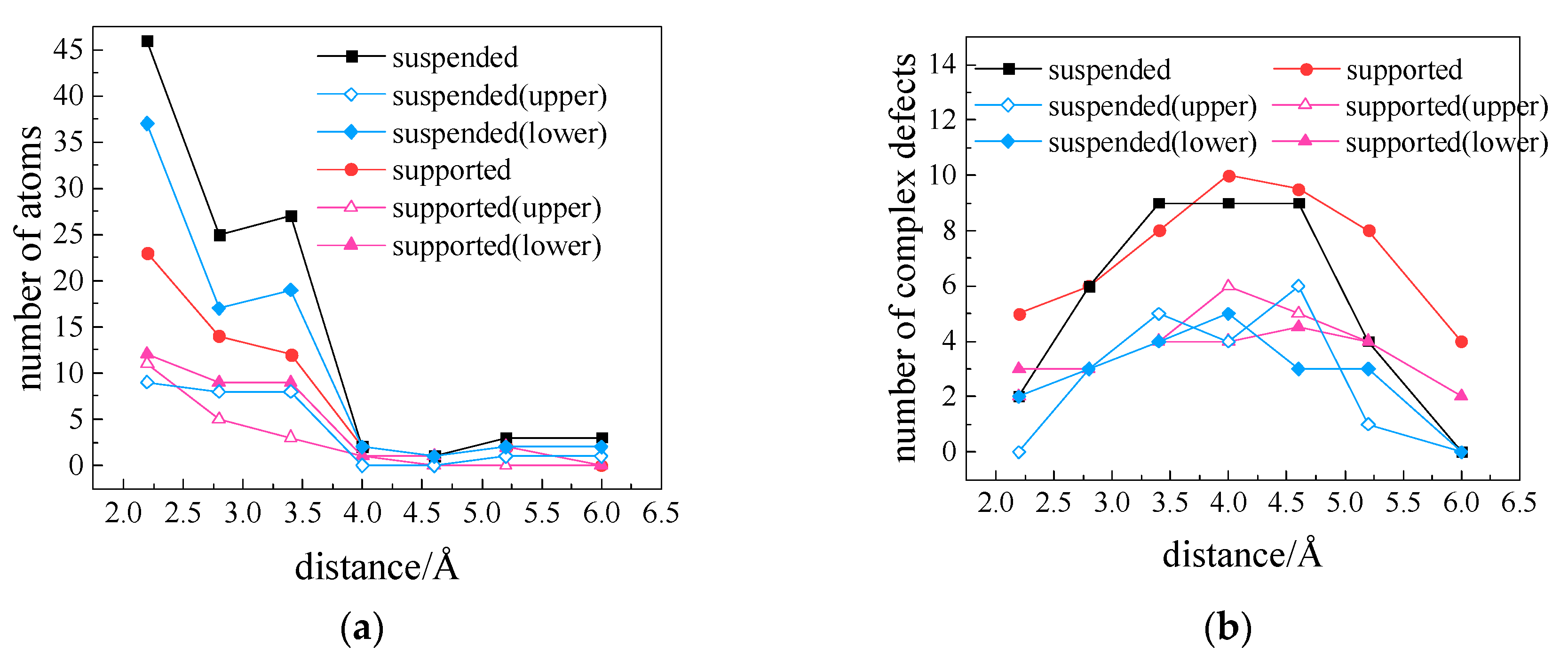
In the simulation, the number of knock-on atoms can describe the number of atoms sputtered away from the surface of graphene. The number of complex defects, referring to defects other than SV/DV, can describe the surface state of graphene and is sensitive to various irradiation conditions. Therefore, knock-on atoms and complex defects are combined to illuminate the process of double-layer suspended graphene defects, as Figure 7 shows. It can be seen from Figure 7a that the number of knock-on atoms decreases with the increase of ion distance from the beginning. Compared with SLG in Figure 6, there is no phase in which the number of knock-on atoms increases with the increase of ion distance. Thus, in BLG irradiation, the influence of indirect action distance is more obvious than direct-action distance. By comparison, radiation damage in BLG is less severe than in SLG; [19] has the same conclusion. Due to the shielding effect of lower graphene, the number of knock-on atoms decreases rapidly with the irradiation density. Even to the end, there is basically no impact atom. Simultaneously, it is found that the number of knock-on atoms in the upper layer was less than the lower layer.
Figure 7b shows that the number of complex defects initially increases, then decreases when the ion distance increases. According to the assumption of the effective range of the incident ions and the information of the (a) diagram, it can be divided into three stages. For short distances, the interaction ranges of incident ions overlap with each other, resulting in a relatively centralized damage to graphene. The radiation damage is mainly manifested by a large number of knock-on carbon atoms and less complex defects. As the distance increases, the total effective action range of ions is raised, which can cause a large defect area. However, the number of knock-on atoms would have been briskly reduced, so much so that thee numerous free atoms remaining near the surface of the graphene would generate a mass of complex defects after irradiation. It can be seen from Figure 7 that the number of knock-on atoms is small at the ion distance of 4.0 Å and the number of complex defects reaches the maximum. When the ion distance continues to increase, the number of knock-on atoms dose not vary and actually has decreased to 0. Meanwhile, the difficulty of merging into complex defects increases enables the number of complex defects to decrease. Finally, the number of complex defects fall off to 0 due to the excessively enormous distance between defects. Wu et al. [27] stated that when the ion energy is low (<40 keV), the ions are mainly absorbed by the upper graphene. Finally, by comparing the two layers of the BLG, the number of knock-on atoms of the upper graphene is almost twice that of the lower graphene, irrespective of the substrate’s presence or absence. However, the number of complex defects in the upper and lower graphene is almost the same. All of them are related to the shielding the effect of graphene in the lower layer on knock-on atoms in the upper layer.

4. Conclusions

Based on the correlation between damage generated and SLGs corresponding irradiation density, we propose a hypothesis for the effective range of incident ions, thereby interpreting the process of changes of direct and indirect action range under different irradiation densities. In the case of a SLG with a copper substrate, the effective action range of the incident ions increases. Although the number of knock-on atoms of the SLG is reduced due to the substrate’s shielding effect, the number of knock-on atoms of the suspended SLG under a certain irradiation density will be lower. As for the BLG, simulation results revealed that the underlying atoms have a shielding effect on the upper graphene, leading to an increase in the number of knock-on atoms and different degree defects of the two graphene layers. Combined with the statistical results of complex defects, the generation process of irradiation damage is explicitly clarified. Moreover, the simulation of irradiation density implies that the indirect action range has a greater influence on the suspended BLG. The damage to the suspended BLG can be neglected when the irradiation density is reduced to a certain extent.

Author Contributions

Conceptualization, J.L. and S.W.; methodology, S.W.; software, K.Y., W.L., and J.L.; validation, S.W., W.L., and L.W.; formal analysis, L.W.; investigation, J.L. and L.W.; data curation, J.L.; writing—original draft preparation, K.Y. and J.L.; writing—review and editing, J.L.; visualization, J.L. and K.Y.; supervision, H.L.; project administration, H.L. All authors have read and agreed to the published version of the manuscript.

Funding

This research was funded by National Natural Science Foundation of China, grant number 61504100, 61434007, and 61376099; the Major Fundamental Research Program of Shaanxi (Grant No.2017ZDJC-26) and the Shanghai Aerospace Science and Technology Innovation Fund.

Conflicts of Interest

The authors declare no conflict of interest.

References

  1. Meyer, J.C.; Geim, A.K.; Katsnelson, M.I.; Novoselov, K.S.; Booth, T.J.; Roth, S. The structure of suspended graphene sheets. Nature 2007, 446, 60–63. [Google Scholar] [CrossRef]
  2. Neto, A.H.C.; Guinea, F.; Peres, N.M.R.; Novoselov, K.S.; Geim, A.K. The electronic properties of graphene. Rev. Mod. Phys. 2009, 81, 109–162. [Google Scholar] [CrossRef] [Green Version]
  3. Qin, H.; Sun, J.; Liang, S.; Li, X.; Yang, X.; He, Z.; Yu, C.; Feng, Z. Room-temperature, low-impedance and high-sensitivity terahertz direct detector based on bilayer graphene field-effect transistor. Carbon 2017, 116, 760–765. [Google Scholar] [CrossRef]
  4. Geim, A.K.; Novoselov, K.S. The rise of graphene. Nat. Mater. 2007, 6, 183–191. [Google Scholar] [CrossRef]
  5. Sasaki, K. Phonon anomaly by massive Dirac fermions of graphene. Phys. Rev. B 2018, 97, 155413. [Google Scholar] [CrossRef] [Green Version]
  6. Peimyoo, N.; Yu, T.; Shang, J.; Cong, C.; Yang, H. Thickness-dependent azobenzene doping in mono- and few-layer graphene. Carbon 2012, 50, 201–208. [Google Scholar] [CrossRef]
  7. Li, Y.; Zhou, Z.; Shen, P.; Chen, Z. Spin gapless semiconductor-metal-half-metal properties in nitrogen-doped zigzag graphene nanoribbons. ACS Nano 2009, 3, 1952–1958. [Google Scholar] [CrossRef]
  8. Yakubu, A.; Sani, G.D.; Abbas, Z. Graphene Synthesis by Chemical Vapour Deposition (CVD): A Review on Growth Mechanism and Techniques. Int. J. Eng. Res. 2019, 8, 15–26. [Google Scholar]
  9. Lehtinen, O.; Kotakoski, J.; Krasheninnikov, A.V.; Tolvanen, A.; Nordlund, K.; Keinonen, J. Effects of ion bombardment on a two-dimensional target: Atomistic simulations of graphene irradiation. Phys. Rev. B 2010, 81, 153401. [Google Scholar] [CrossRef] [Green Version]
  10. Choubak, S.; Levesque, P.L.; Gaufres, E.; Biron, M.; Desjardins, P.; Martel, R. Graphene CVD: Interplay Between Growth and Etching on Morphology and Stacking by Hydrogen and Oxidizing Impurities. Phys. Chem. C 2014, 118, 21532–21540. [Google Scholar] [CrossRef]
  11. Krasheninnikov, A.V.; Banhart, F. Engineering of nanostructured carbon materials with electron or ion beams. Nat. Mater. 2007, 6, 723–733. [Google Scholar] [CrossRef]
  12. Kwieciñski, W.; Kai, S.; Poelsema, B.; Zandvliet, H.J.W.; Bampoulis, P. Chemical vapor deposition growth of bilayer graphene in between molybdenum disulfide sheets. J. Colloid Interface Sci. 2017, 505, 776–782. [Google Scholar] [CrossRef] [Green Version]
  13. Liang, Z.; Xu, Z.; Yan, T.; Ding, F. Atomistic simulation and the mechanism of graphene amorphization under electron irradiation. Nanoscale 2014, 6, 2082. [Google Scholar] [CrossRef]
  14. Lucchese, M.M.; Stavale, F.; Ferreira, E.H.M.; Vilani, C.; Moutinho, M.V.O.; Capaz, R.B.; Achete, C.A.; Jorio, A. Quantifying ion-induced defects and Raman relaxation length in graphene. Carbon 2010, 48, 1592–1597. [Google Scholar] [CrossRef]
  15. Li, W.; Wang, X.; Zhang, X.; Zhao, S.; Duan, H.; Xue, J. Mechanism of the defect formation in supported graphene by energetic heavy ion irradiation: The substrate effect. Sci. Rep. 2015, 5, 9935. [Google Scholar] [CrossRef] [Green Version]
  16. Zeng, J.; Yao, H.J.; Zhang, S.X.; Zhai, P.F.; Duan, J.L.; Sun, Y.M. Swift heavy ions induced irradiation effects in monolayer graphene and highly oriented pyrolytic graphite. Nucl. Instrum. Methods Phys. Res. Sect. B Beam Interact. Mater. At. 2014, 330, 18–23. [Google Scholar] [CrossRef]
  17. Zhao, S.; Xue, J.; Wang, Y.; Yan, S. Effect of SiO2 Substrate on the irradiation-assisted manipulation of supported graphene: A molecular dynamics study. Nanotechnology 2012, 23, 285703. [Google Scholar] [CrossRef]
  18. Zhao, D.; Wang, Q.; Ding, J. Physical mechanism of swift heavy ion irradiation effect in graphene. Radiat. Eff. Defects Solids 2019, 174, 617–623. [Google Scholar] [CrossRef]
  19. Zhao, D. Multiscale Simulations of Irradiation Effects of Bilayer Graphene Induced by Swift Heavy Ions. J. Comput. Theor. Nanosci. 2017, 14, 485–489. [Google Scholar] [CrossRef]
  20. Nebogatikova, N.A.; Antonova, I.V.; Erohin, S.V.; Krasheninnikov, A.V. Nanostructuring few-layer graphene films by swift heavy ions for electronic application: Tuning of electronic and transport properties. Nanoscale 2018, 10, 14499–14509. [Google Scholar] [CrossRef]
  21. Liao, W.; Alles, M.; Zhang, E.X. Monte Carlo Simulation of Displacement Damage in Graphene. IEEE Trans. Nucl. Sci. 2019, 66, 1730–1737. [Google Scholar] [CrossRef]
  22. Vazquez, H.; Ahlgren, E.H.; Ochedowski, O.; Krasheninnikov, A.V. Creating nanoporous graphene with swift heavy ions. Carbon 2017, 114, 511–518. [Google Scholar] [CrossRef] [Green Version]
  23. Car, R.; Parrinello, M. Unified Approach for Molecular Dynamics and Density-Functional Theory. Phys. Rev. Lett. 1985, 55, 2471–2474. [Google Scholar] [CrossRef] [Green Version]
  24. Saito, R.; Fujita, M.; Dresselhaus, G.; Dresselhaus, M.S. Electronic structure of chiral graphene tubules. Appl. Phys. Lett. 1992, 60, 2204–2206. [Google Scholar] [CrossRef]
  25. Jiang, J.W.; Wang, J.S.; Li, B. Young’s modulus of graphene: A molecular dynamics study. Phys. Rev. B 2009, 80, 113405. [Google Scholar] [CrossRef] [Green Version]
  26. Stuart, S.J.; Tutein, A.B.; Harrison, J.A. A reactive potential for hydrocarbons with intermolecular interactions. J. Chem. Phys. 2000, 112, 6472–6486. [Google Scholar] [CrossRef] [Green Version]
  27. Wu, X.; Zhao, H.; Zhong, M. Molecular dynamics simulation of graphene sheets joining under ion beam irradiation. Carbon 2014, 66, 31–38. [Google Scholar] [CrossRef]
  28. Ong, Z.Y.; Pop, E. Molecular dynamics simulation of thermal boundary conductance between carbon nanotubes and SiO2. Phys. Rev. B 2010, 81, 155408. [Google Scholar] [CrossRef] [Green Version]
  29. Favata, A.; Micheletti, A.; Podio-Guidugli, P.; Pugno, N. Geometry and Self-stress of Single-Wall Carbon Nanotubes and Graphene via a Discrete Model Based on a 2nd-Generation REBO Potential. J. Elast. 2016, 125, 1–37. [Google Scholar] [CrossRef] [Green Version]
  30. Banhart, F.; Kotakoski, J.; Krasheninnikov, A.V. Structural defects in graphene. ACS Nano 2011, 5, 26–41. [Google Scholar] [CrossRef] [Green Version]
  31. Boukhvalov, D.W.; Katsnelson, M.I. Chemical Functionalization of Graphene with Defects. Nano Lett. 2008, 8, 4373–4379. [Google Scholar] [CrossRef] [Green Version]
  32. Kotakoski, J.; Krasheninnikov, A.V.; Kaiser, U.; Meyer, J. From point defects in graphene to two-dimensional amorphous carbon. Physrevlett 2011, 106, 105505. [Google Scholar] [CrossRef] [Green Version]
  33. Wang, S.; Zhang, Q.; Yin, K.; Gao, B.; Zhang, S.; Wang, G.; Liu, H. The Influence of Copper Substrates on Irradiation Effects of Graphene: A Molecular Dynamics Study. Materials 2019, 12, 319. [Google Scholar] [CrossRef] [Green Version]
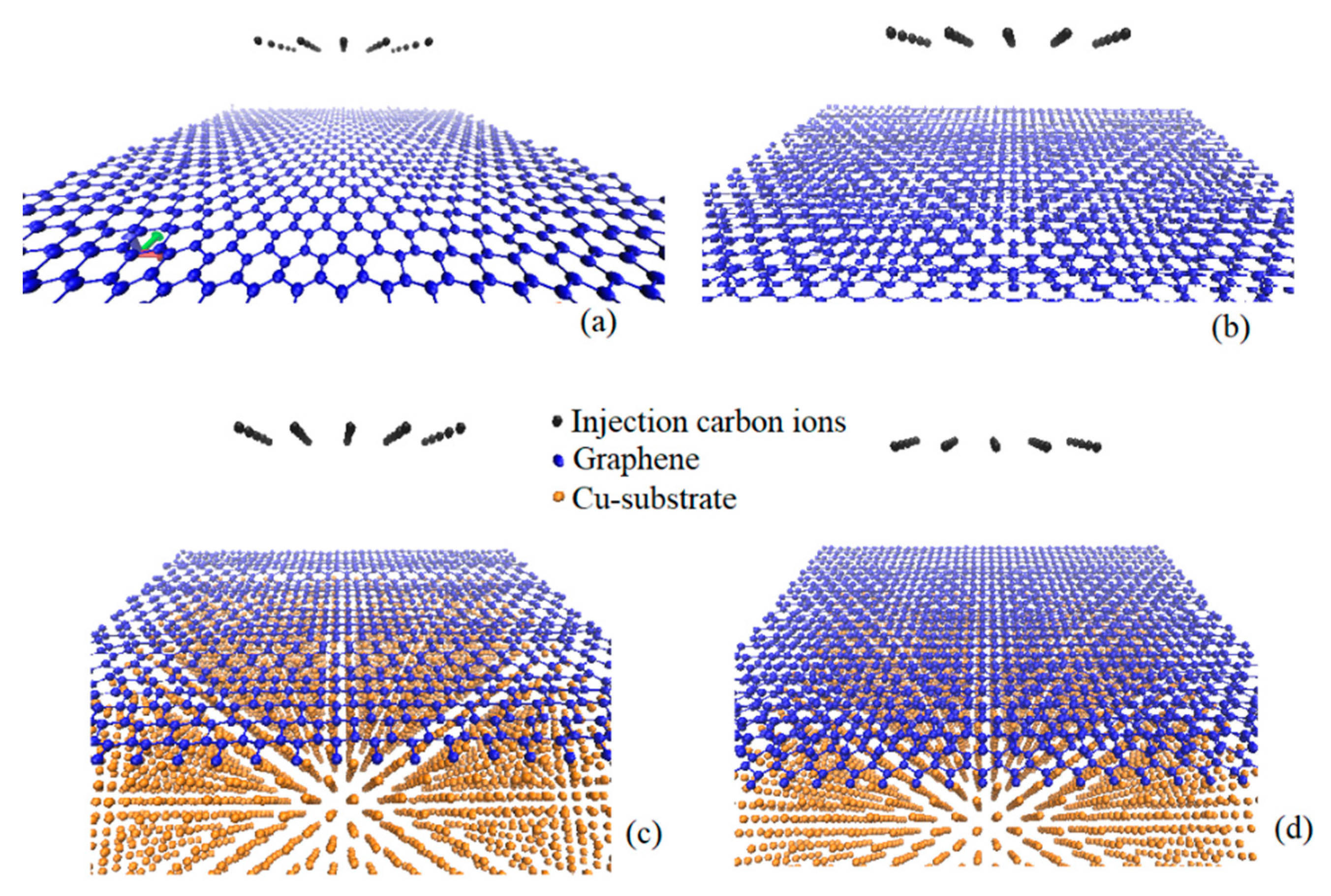
Figure 1. Atomic configuration of graphene: (a) single-layer graphene; (b) bi-layer graphene; (c) single-layer graphene on copper substrate; and (d) bi-layer graphene on copper substrate.
Crystals 10 00158 g001
Figure 2. The relationship between defect and irradiation density of suspended single-layer suspended graphene (SLG) at irradiation energy of 0.87, 1.96, and 4.41 keV. The dashed lines indicate the position of (R + r), i.e. the position where the number of knock-on atoms rapidly decreases from the maximum value.
Crystals 10 00158 g002
Figure 3. Schematic diagram of the effective range of incident ions.
Crystals 10 00158 g003
Figure 4. The correlation between effective range and irradiation density.
Crystals 10 00158 g004
Figure 5. Simulation of irradiation of graphene by drawing. The atoms in the red circle are the covered atoms.
Crystals 10 00158 g005
Figure 6. The relationship between defect and irradiation density of suspended and supported SLG (irradiation energy of 4.41 keV; irradiation dose of 25).
Crystals 10 00158 g006
Figure 7. The relationship between defect and irradiation density of suspended and supported bi-layer graphene (BLG) (irradiation energy of 4.41 keV; irradiation dose of 25): (a) number of knock-on atoms; (b) number of complex defects.
Crystals 10 00158 g007
Table 1. Calculated value of r and R.
Irradiation Energy/keVR/År/Å(R + r)/Å
0.8730.753.75
1.962.40.673.07
4.411.80.62.4