Article

Structure of Imidazolium-N-phthalolylglycinate Salt Hydrate: Combined Experimental and Quantum Chemical Calculations Studies

1
Department of Chemistry, Indian Institute of Technology-Kanpur, Kanpur 208016, India
2
Department of Chemistry, College of Sciences, King Saud University, P.O. Box 2455, Riyadh 11451, Saudi Arabia
3
Department of Chemistry, Aligarh Muslim University, Aligarh-202002, India
*
Author to whom correspondence should be addressed.
Crystals 2020, 10(2), 91; https://doi.org/10.3390/cryst10020091
Submission received: 7 January 2020 / Revised: 28 January 2020 / Accepted: 30 January 2020 / Published: 5 February 2020
(This article belongs to the Special Issue Charge Transfer Crystals)

Abstract

:
An organic supramolecular salt hydrate (imidazolium:N-phthalolylglycinate:H2O; IM+–NPG–HYD) has been examined for its charge-transfer (CT) characteristics. Accordingly, IM+–NPG–HYD has been characterized thoroughly using various spectroscopic techniques. Combined experimental and quantum chemical studies, along with wave function analysis, were performed to study the non-covalent interactions and their role in CT in the supramolecular salt hydrate. Notably, IM+–NPG–HYD crystalizes in two configurations (A and B), both of which are held together via non-covalent interactions to result in a three-dimensional CT supramolecular assembly. The through-space CT occurs from NPG (donor) to IM+ (acceptor), and this was mediated via non-covalent forces. We demonstrated the role of π–π stacking interactions (mixed-stacking donor-acceptor interactions) in the presence of charge-assisted hydrogen bonds in the regulation of CT properties in the self-assembly of the IM+–NPG–HYD salt hydrate.

1. Introduction

The self-assembly characteristics of non-covalent interactions, such as hydrogen bonds, π–π stacking, and other weak van der Waals forces participating in (bio)chemical processes, have inspired supramolecular chemists to employ them effectively in crystal engineering [1,2]. Crystal engineering is defined as the study of intermolecular interactions in terms of crystal packing and exploiting such kinds of non-covalent interactions for designing multifunctional materials having the desired properties [3,4]. It hasbeen proven that different intermolecular interactions and/or crystal packing could highly modulate the optical and electronic properties of molecular crystals [5]. For example, the formation of multi-component molecular materials (co-crystals, salts, and salt hydrates) has been extensively investigated with the development of crystal engineering or supramolecular chemistry [6,7,8].
Organic co-crystals, salts, and salt hydrates formed with different molecular moieties through intermolecular non-covalent interactions are attracting the attention of many researchers globally because of their applications in charge transport [9,10,11], photovoltaics [12], tunable light emitters [13,14], photoconductivity [15,16], ferroelectrics [17,18], nonlinear optics [19,20], light-driven actuators [21], and pharmaceuticals [22]. Moreover, the dynamics of a proton or a hydrogen atom in the H-bonded CT-supramolecular assembly has attracted greater attention, because it plays a crucial role in (bio)chemical reactions and some physical properties, such as dielectricity and proton conductivity [22,23,24,25].
Hence, a profound understanding of non-covalent interactions and the prediction of their strength are critical to designing the desired functional materials. Remarkably, the physical and chemical properties of co-crystals are not simply the sum of the molecular properties of their constituent molecular moieties [26,27]. In this regard, co-crystallization or crystallization of multi-component molecular systems (co-crystals, salts, and salt hydrates) opens the door not only for the development of new multifunctional materials but also for the examination of novel phenomenon such as charge-transfer along the molecular crystallographic axis [28,29].
In 1952, Mulliken laid the foundation stone of the concept of charge transfer (CT) [30]. He observed new absorption bands for multicomponent molecular complexes; these bands were absent from the spectra of any of the constituent components individually. In addition, these molecular complexes contain an electron-donor component and an electron-acceptor component with low ionization energy and high electron affinity, respectively. Such type of multicomponent molecular complexes has an ionic excited state (ψ1 = D+···A) with comparatively low excitation energy, and mixing this state with the neutral ground state (ψ0 = D···A) results in ψ0 + λψ1 and ψ1 – λψ0 states. The transition dipole moment between these states is very large, resulting in strong electronic absorption; this transition dipole moment cannot occur in isolated components, be it an isolated donor or an isolated acceptor. Strikingly, the mixing of the molecular components results in color change because of the low excitation energy that may lie in the visible region of the spectrum. Mulliken observed that the mixing must lower the energy of the complex relative to the energy of the state ψ0: a charge-transfer contribution to the interaction energy. Hence, the CT interaction is the consequence of the charge density being transferred from the electron-donor component to the electron acceptor component, and the charge-transfer energy is the lowering in the energy associated with this transfer. Therefore, regarding the above-described Mulliken’s CT concept and crystal-engineering concept, we combine both the concepts to achieve the desired charge-transfer complex.
In this study, we prepare a charge-transfer IM+–NPG–HYD with mixed-stacking and charge-assisted hydrogen bonds between IM+ and NPG- moieties. The proton transfer occurred from the carboxylic group of NPG to the amine group of IM, resulting in a charge-assisted hydrogen bond between both the moieties [31]. Generally, charge-assisted hydrogen bonding is stronger than normal hydrogen bond because of the presence of additional electrostatic interactions; consequently, the molecular components act as charge carriers. Nevertheless, charge-assisted hydrogen bonds have not been studied much as a designing factor in the self-assembly process of supramolecular entities [32,33,34,35,36,37]. There is still much scope for developing, understanding, and implementing charge-assisted hydrogen bonds in the context of crystal engineering.

2. Result and Discussion

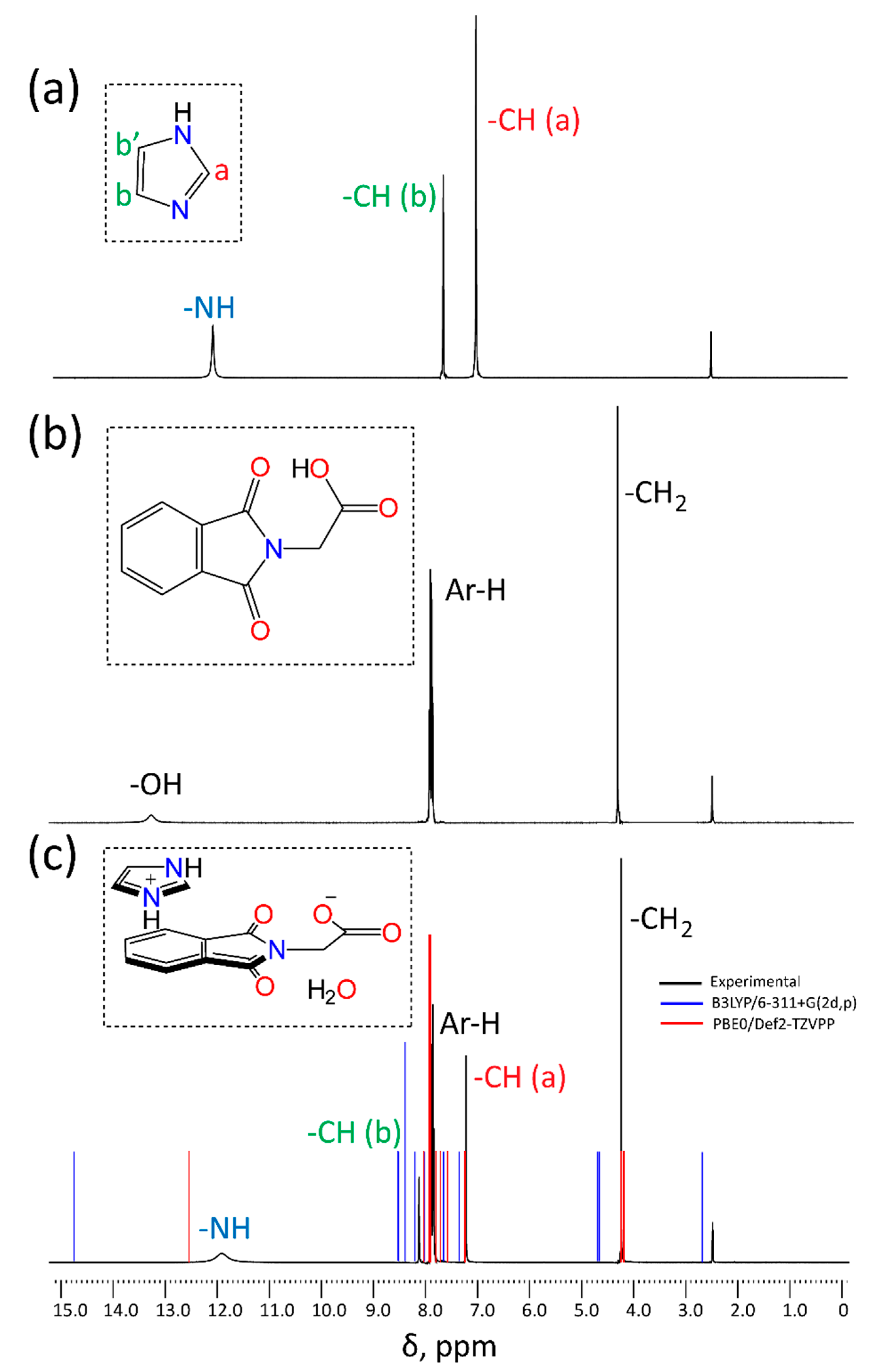
2.1. Spectroscopic Analysis
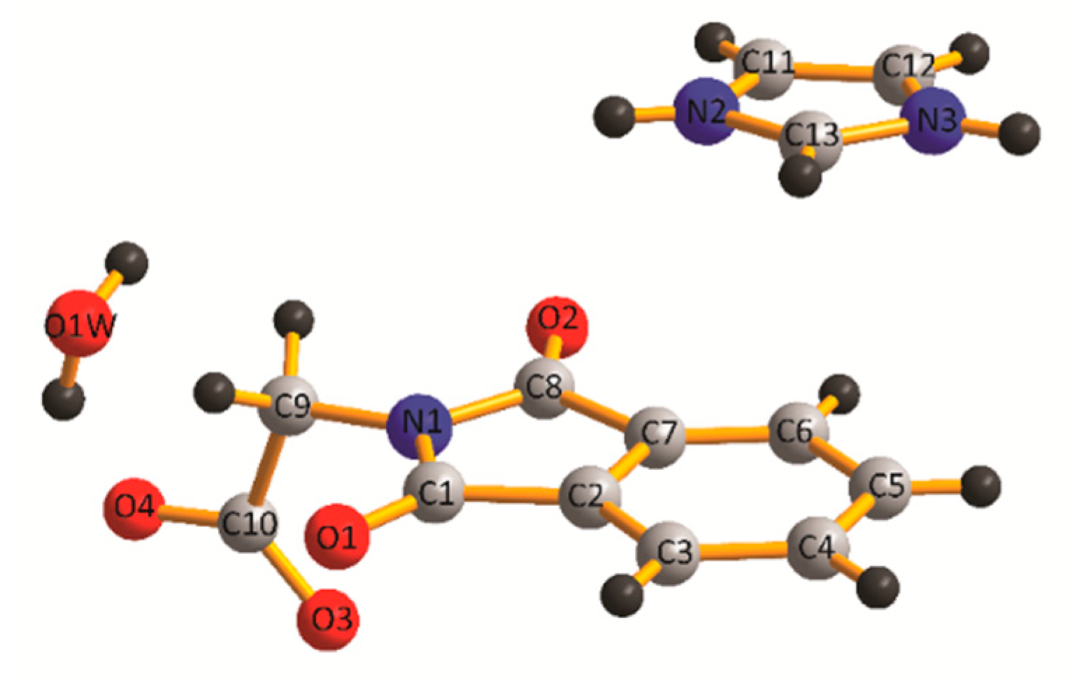
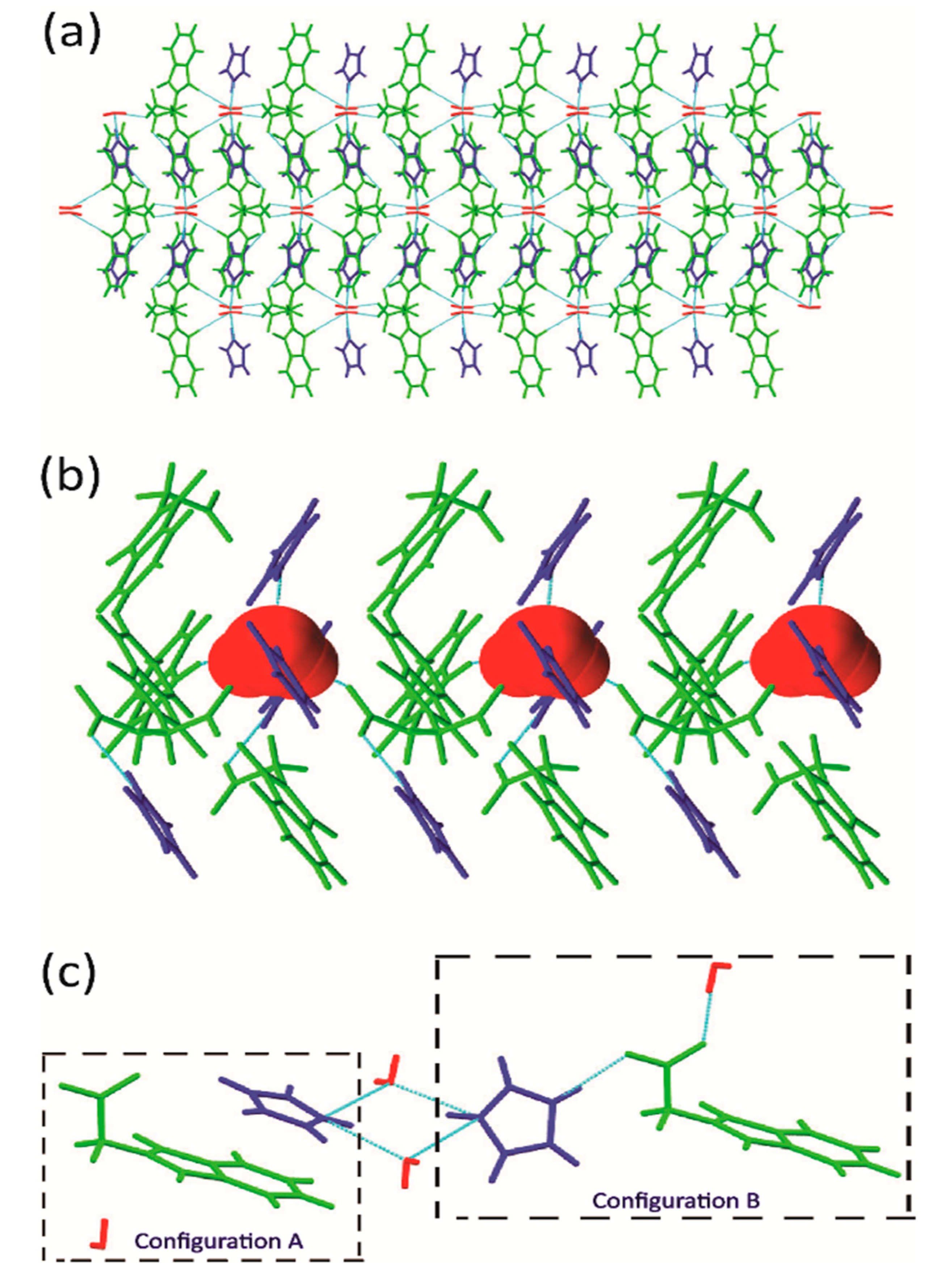
A shift in the vibrational frequency of the multi-component molecular crystal with respect to the individual molecular entities denotes the formation of new hydrogen bonds and other weak noncovalent forces [38,39,40]. As depicted in Figure S1, from the IR spectrum of NPG, carbonyl stretching frequencies of the carboxylic acid are observed at 1724.17 and 1415.18 cm−1. The carbonyl stretching bands were the most distinctive IR features to distinguish the carboxylic acid group from the conjugate carboxylate moiety [41,42]. The asymmetric and symmetric stretching frequencies of the carboxylate group (COO) were observed at 1708.60 and 1419.98 cm−1, respectively. Significant shifts in these vibrational frequencies were observed in IM+–NPG–HYD (see Figure S1 in Supplementary Materials), signifying the proton transfer from the carboxylic-acid group [43]. A further relevant observation is that the IR spectrum of the IM+–NPG–HYD salt displayed a characteristic band at the 3502.27 cm−1, revealing the υOH stretching frequency of hydrogen-bonded lattice water [44]. Furthermore, the vibrational frequencies have also been calculated to support and assign the mode of vibration, observed experimentally. The IR spectrum has been simulated using DFT/M062X/6-31G** method given in Figure S2. The calculated frequencies and other spectral features were found to be within the range, shown in Table 1. Three factors could be responsible for the deviation in the computed spectrum: (1) the environmental factor as DFT calculations were performed with solvation effect (liquid phase, EtOH as solvent) while experimental data was obtained at solid-state; (2) the calculated frequencies are included only harmonic while experimental have both harmonic and anharmonic effect; and (3) basis set and DFT functional discrepancies. However, the pattern and trend of spectra were quite similar in both the cases which support the experimental observations.
To examine IM and NPG, as well as the self-assembly and molecular recognition in the solution phase, tandem mass-spectroscopy (ESI-MS/MS) was performed. A m/z 294.1 molecular ion peak, which is precisely matched with the sum of the IM+–NPG–HYD salt’s hydrate, [C13H13N3O5 + 3H+], was designated as the primary ion in the first stage (Figure S3).
The UV–vis spectra of IM, NPG, and IM+–NPG–HYD salt hydrate were recorded in the solution state (EtOH, 1 × 10⁻⁴ M) to explore the possibility of CT interaction between the NPG- and IM+ molecular entities within the IM+–NPG–HYD salt hydrate (Figure 1). The absorption spectrum of the IM+–NPG–HYD salt hydrate is characterized by the appearance of a new absorption band in the visible region (380–550 nm). Neither NPG nor IM displayed any absorption band in this region. Therefore, this new absorption band in the visible region (380–550 nm) is attributed to the formation of donor-acceptor charge transfer IM+–NPG–HYD salt hydrate [45,46,47,48]. In comparison to UV–vis spectra of IM, NPG, and IM+–NPG–HYD salt hydrate, a remarkable bathochromic shift in the absorption bands appeared in the region of 250–350 nm is also observed in IM+–NPG–HYD salt hydrate. The observed significant bathochromic shift in the 250–350 nm absorption band is also indicated the charge transfer nature of the IM+–NPG–HYD salt hydrate [45,46,47,48]. Furthermore, TDDFT calculation has been carried out at the cam-B3LYP/cc-pVTZ level of theory to calculate the vertical excitation energies and oscillator strengths of the electronic transition. The TDDFT simulated UV–vis spectrum (vertical excitation energies and oscillator strengths) of IM+–NPG–HYD salt hydrate is in good agreement with the experimental spectrum. The TDDFT results suggested that a broad CT band in the range of 400–550 nm, comprises CT0 → CT1, CT0 → CT2, CT0 → CT3, and CT0 → CT4 electronic transitions located at 430, 446, 513, and 534 nm, respectively (Figure 1). The vertical excitation energies for electronic transitions CT0 → CT1, CT0 → CT2, CT0 → CT3, and CT0 → CT4 were found to be 1.72, 1.79, 2.06, and 2.14 eV, respectively. Moreover, the molecular orbitals involved in the electronic transitions CT0 → CT1, CT0 → CT2, CT0 → CT3, and CT0 → CT4 were found to be HOMO → LUMO, HOMO-2 → LUMO, HOMO → LUMO+1, and HOMO-1 → LUMO+1 excitations, respectively [48]. The detail description of the CT transfer nature of the IM+–NPG–HYD salt hydrate is given in Section 2.5.
The 1H NMR spectra of NPG, IM, and IM+–NPG–HYD were recorded in DMSO-d6 solution and depicted in Figure 2. The 1H NMR spectrum of NPG exhibited signals at 4.31, 7.85–7.93, and 13.25 ppm, attributed to the protons of the –CH2, aromatic ring, and –COOH group, respectively. In the 1H NMR spectrum of IM, signals exhibited at 7.01–7.64 ppm are attributed to the aromatic protons of the ring, while an upfield signal appeared at 12.07 ppm is attributed to the –NH proton. Compared with the free NPG and IM 1H NMR spectra, a significant peak shift was observed in the spectrum of IM+–NPG–HYD, indicating the existence of hydrogen bonds and other noncovalent interactions also in the solution phase. A broad signal with low intensity at 11.90 ppm in IM+–NPG–HYD is attributed to the –NH proton. Additionally, 1H NMR spectrum for salt hydrated simulated theoretically using DFT/B3LYP/6-311 + G(2d,p) and PBE0/Def2-TZVPP methods to assign the experimentally observed 1H NMR signals. The simulated 1H NMR spectrum at PBE0/Def2-TZVPP level of theory is found to be in good match with the experimental one with a slight deviation. This deviation could be attributed to the absence of a solvation effect in the calculated shielding values (gas-phase) whereas the experimental values recorded in the solution phase.

2.2. Crystal Structure of IM+–NPG–HYD (1:1:1)

The IM+–NPG–HYD salt was block-shaped and crystallized in the monoclinic C2/c space group. The asymmetric unit consists of an NPG, an IM+ and a water molecule (see Figure 3), and the crystal packing is depicted in Figure S4. The details of bond distances, hydrogen bonds, structure refinement, and crystal data were presented in Table 2 and Table 3. The C–O distances in the C10–O3 and C10–O4 of the carboxylic acid group in NPG are 1.243(3) and 1.264(3) Å, respectively, indicating the presence of a deprotonated form of NPG in the IM+–NPG–HYD salt hydrate. There are two configurations, A and B, present in the supramolecular assembly of IM+–NPG–HYD. Both these configurations are held together through the water molecule via hydrogen bonds. In configuration A, IM+ and NPG molecules are arranged alternatively and stacked on each other through π–π interactions (centroid–centroid separation: 3.760 Å) to form a one-dimensional donor–acceptor (···DADADA···) CT-chain (Figure 4a). In configuration B, NPG is linked to IM+ and H2O by hydrogen bonds, further self-assembling alternatively to each other to form a one-dimensional donor–acceptor CT-chain.
Furthermore, these one-dimensional CT-chains are perpendicular to each other and connected with a water molecule via N2–H2···O4, N3–H3A···O1W, O1W–H1WB···O3, and O1W–H1WA···O2 hydrogen bonds, resulting in 3D supramolecular CT assembly (Figure 5). Furthermore, geometry optimizations of both the configurations have been carried out at the DFT level of theory using the M06-2X/6-31G** method and in good agreement with the crystal structure data. The calculated bond distances and the distances between IM+ and NPG are given in Table 1. Slight deviation observed in the calculated structure observed due to the fact that the DFT calculation performed in solvent phase EtOH as a solvent using the CPCM solvation method while experimental data collected from the solid-state material (Figure S5). We have also calculated the interfragmentary interaction energy from the Hirshfeld charges and depicted in Figure 4.

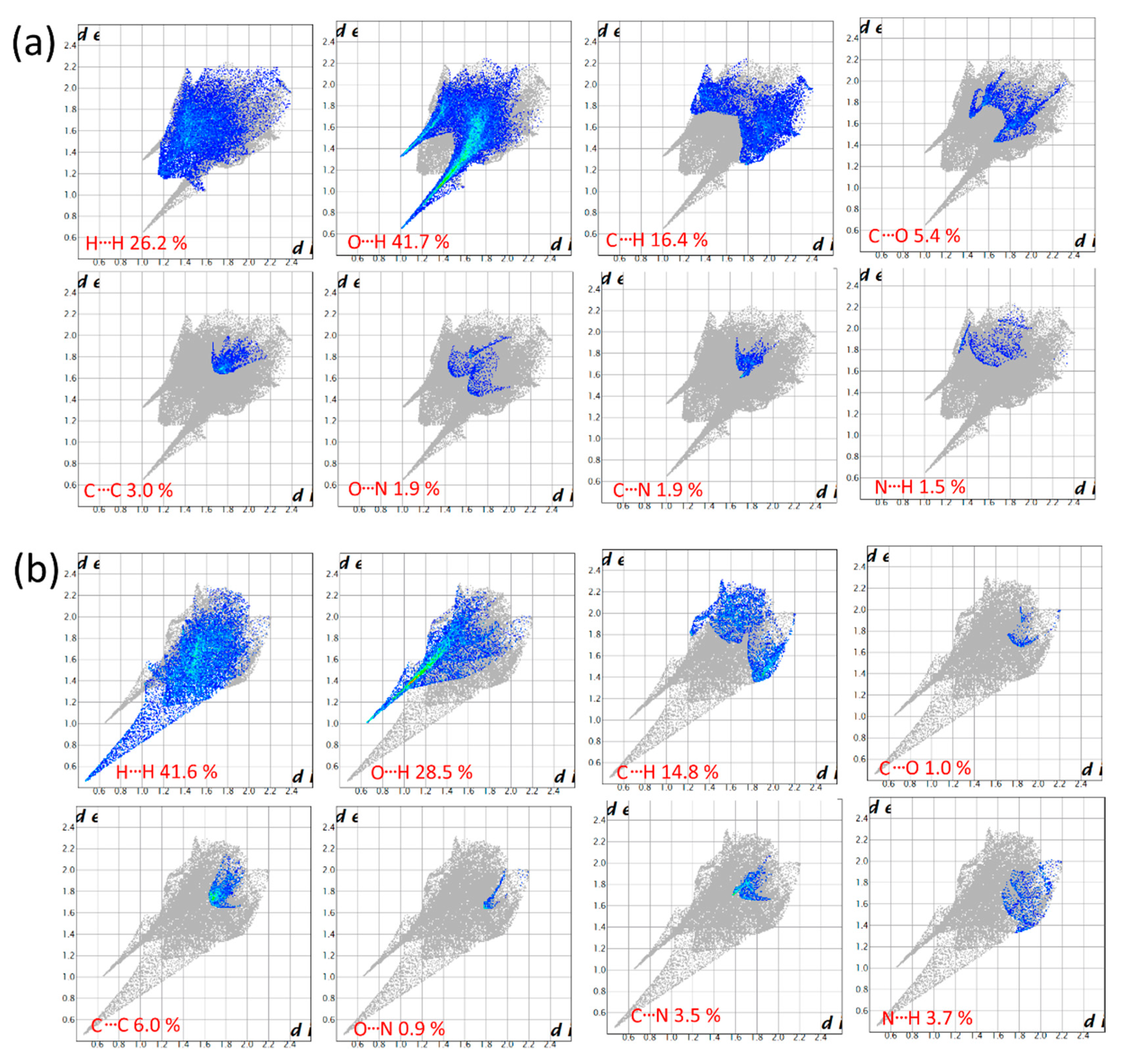
2.3. Hirshfeld Surface Analysis

Hirshfeld surface analysis of charge transfer IM+–NPG–HYD gives useful information about the role of different intermolecular interactions in determining the optical and electronic properties. The Hirshfeld surface of IM+ and NPG separately presented in Figure S5 and plotted over a dnorm range from −1.138 to 0.880 Å (IM+) and −0.731 to 1.024 Å (NPD), shape index from −1.0 to 1.0 Å, and curvedness from −4.0 to 0.4 Å. All these three surfaces are transparently displayed to visualize IM+–NPG–HYD in an analogous orientation, around which they were mapped. We have taken the asymmetric unit among the entire unit cell from the single-crystal X-ray data. The information present in the hydrogen-bonding tables is corroborated adequately with the red spots, where the large rounded depressions (deep red) visible on the dnorm surface are indicative of the hydrogen-bonding interaction, and other visible spots are indicative of the H···H, C···C, C···N, C···H, O···O, O···N, and C···O interactions. The dominant O···H and C···H interactions can be viewed in the Hirshfeld surface map by the light red circular region in Figure S6a. These light red spots are the result of the N···H, C···O, C···N, and C···C interactions. Other visible spots on the surface indicate H···H and further weaker and longer interactions apart from the hydrogen bonds. The presence of π–π stacking interactions between the fused aromatic ring of NPG moiety and the five-membered heteroaromatic ring of IM+ moiety was reflected in the shape-index surface, as depicted in Figure S5b. As the inspection on the Hirshfeld surface show adjacent red and blue triangles on the shape-index surface, a characteristic feature is the presence of π–π stacking interactions. Moreover, a clear flat region in the direction of the bottom of both sides of the NPG and IM+ moieties is evident on the curvedness surface, also depicting the presence of π–π stacking interactions between these two moieties, as depicted in Figure S5c.
Furthermore, we have also presented two-dimensional (2D) fingerprint plots for each observed interaction between the atom pairs in the salt hydrate. The fingerprint plots can be decomposed to highlight particular atoms of pairwise interactions (Figure 6). This decomposition allows the parting of contributions from different types of interaction, which overlay the full fingerprint plot. Complementary regions are visible in the fingerprint plots, where one moiety acts as a donor (de > di) and the other as an acceptor (de < di). The H···O/O···H intermolecular interactions appear as distinct spikes in the 2D fingerprint plot (see Figure 6). The N···H intermolecular interaction appears as two small broad spikes on in the 2D fingerprint plot. The proportion of H···O/O···H interactions consists of 18.7% and 23.3% of the total Hirshfeld surface area. Such kind of dissimilar proportion for O···H interactions characterizes the oxygen of water interacting with the carbonyl oxygen (C=O) of the NPG moiety and is accountable for the building of the supramolecular self-assembly. A similar type of unequal proportions was also observed for C···H, C···N, N···H, and C···O interactions, clearly indicating that these interactions participate in the growth of 3D supramolecular assembly of IM+–NPG–HYD.

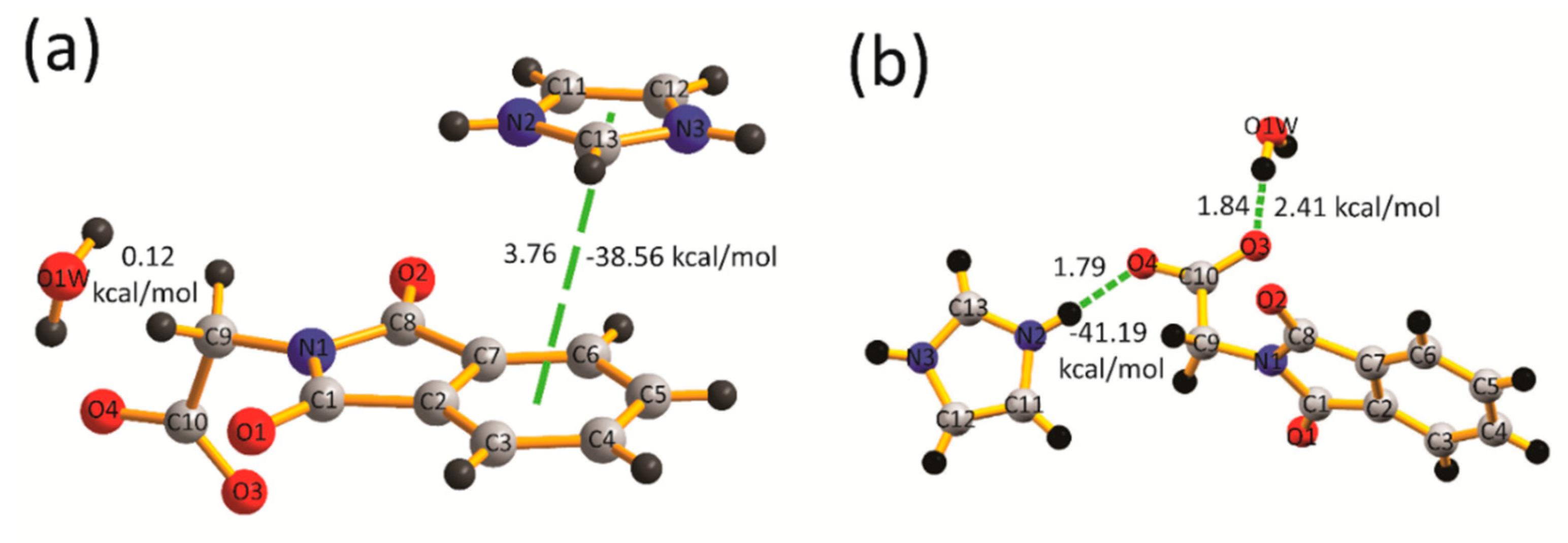
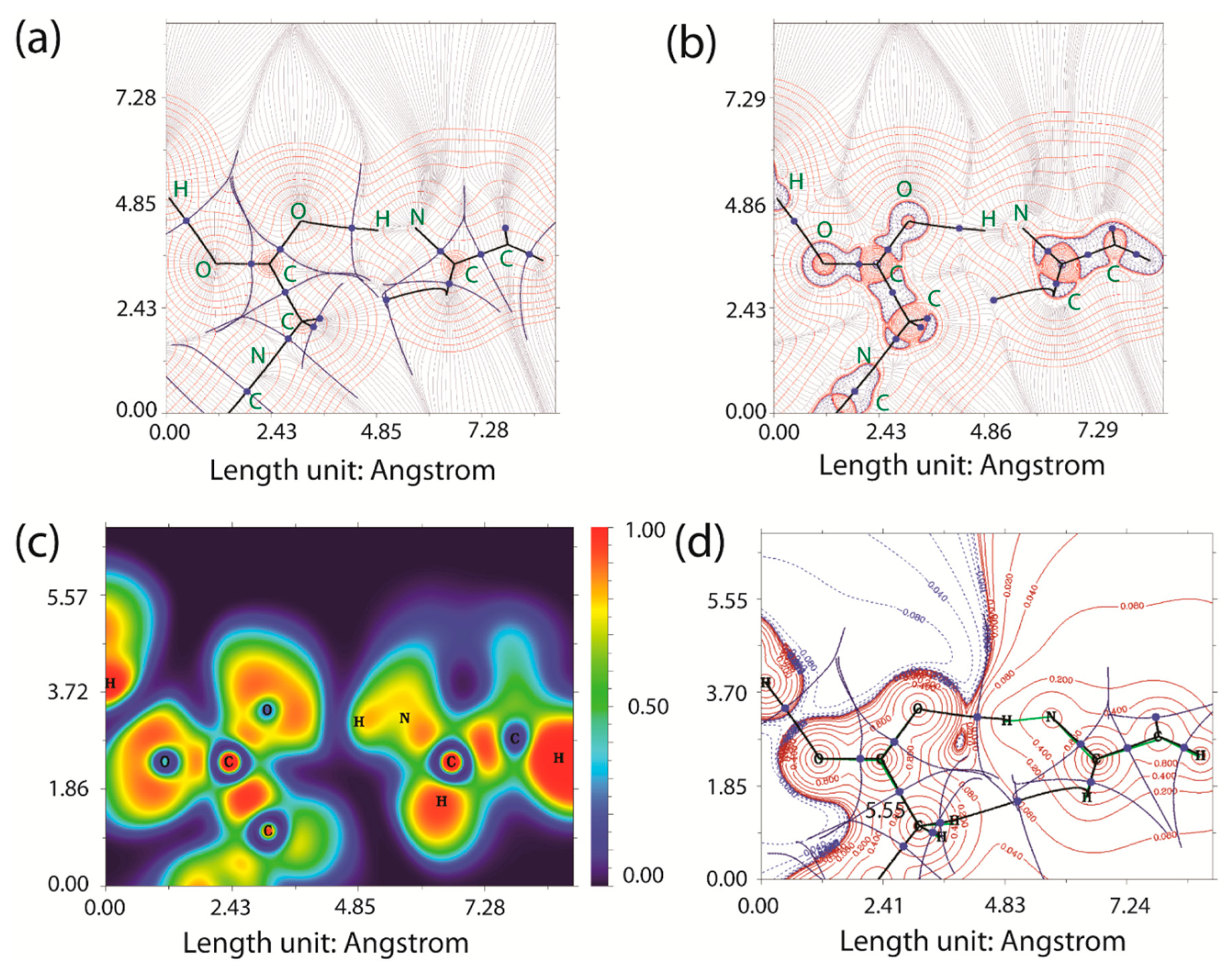
2.4. Quantum-Theory-of-Atoms-in-Molecules Analysis
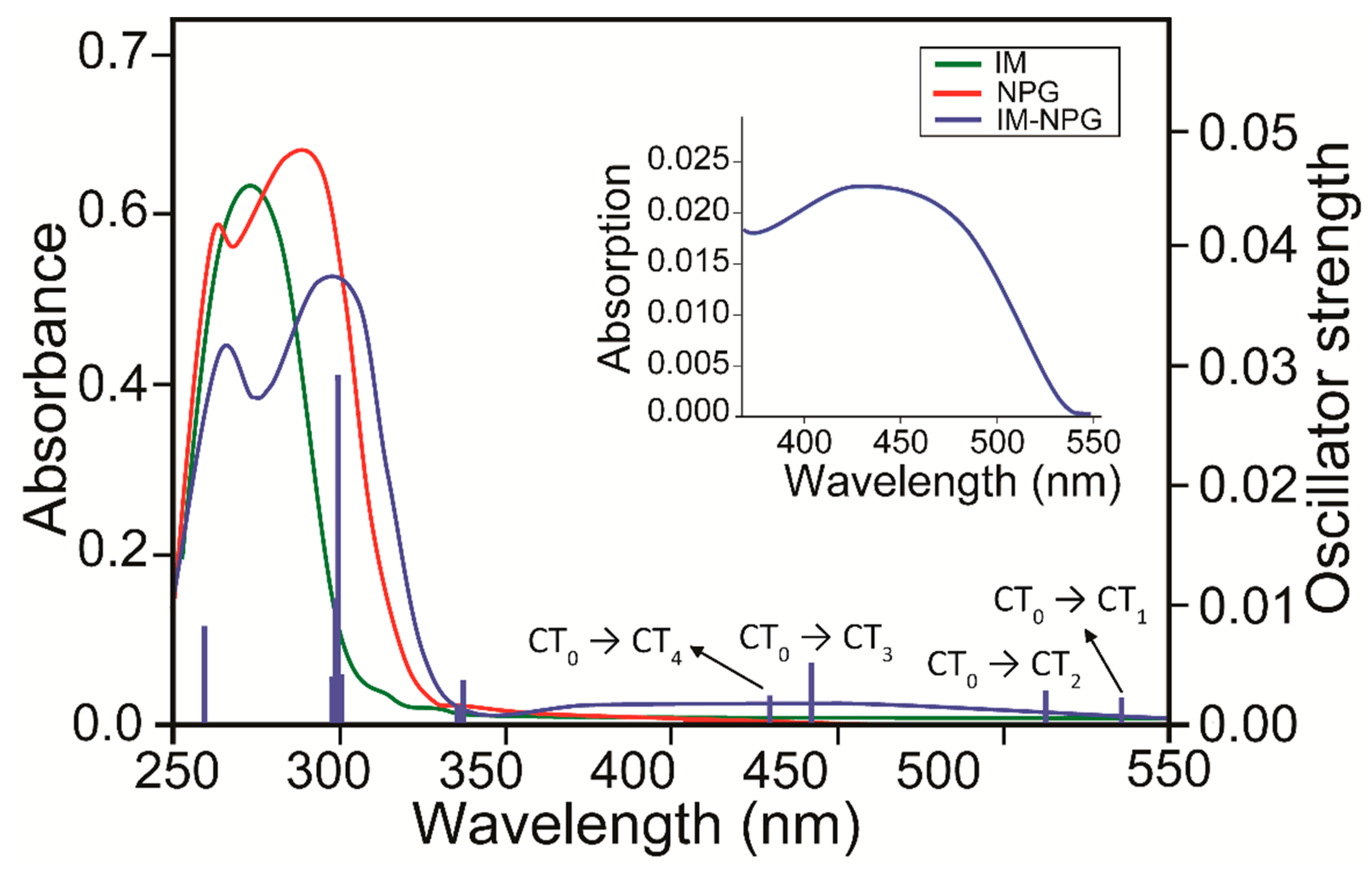
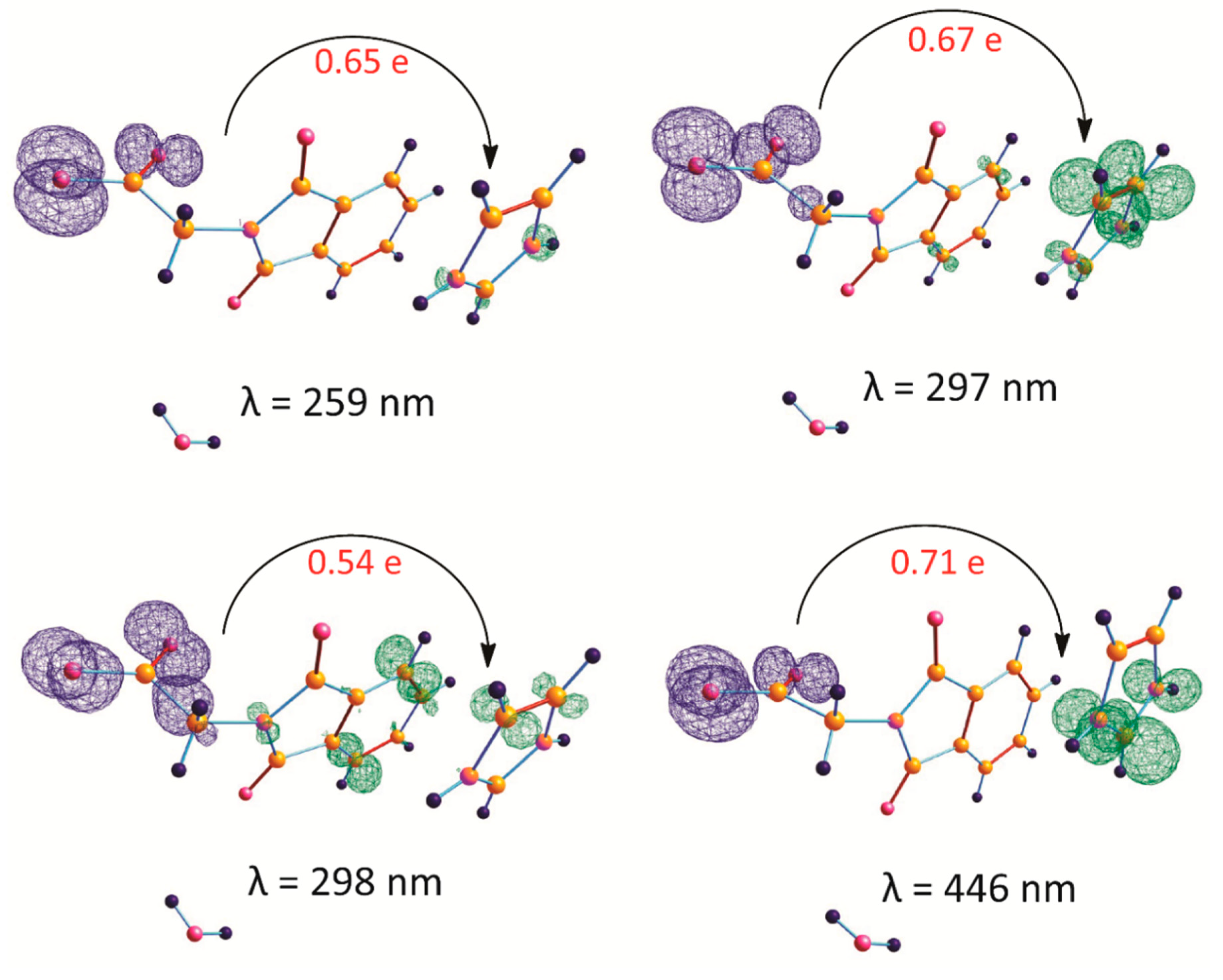
The topology of calculated electron density at the DFT/M062X/cc-pVTZ level of theory has been analyzed by employing the QTAIM approach. The quantum theory of atoms-in-molecules (QTAIM) has proved to be a great tool for investigating a variety of chemical interactions. According to the QTAIM, which was developed by Bader, a chemical bond is distinctively described by a line of maximum electron density linking two bonded atoms (bond path, BP) on which a bond critical point (BCP) (3, –1) is present [49,50]. Koch and Popelier [51] quantified that a hydrogen bond would be present in a molecular structure if the electron density is within the range of 0.002–0.040 atomic unit (a.u.), and the resultant Laplacian within the range of 0.024–0.139 a.u. The presence of hydrogen bonds was further supported by Rozas et al. According to Rozas et al. [52,53], these hydrogen-bond interactions may be categorized as follows: (i) strong and covalent hydrogen bond, when (∇2ρ) < 0 and H < 0; (ii) medium and partially covalent hydrogen bond, when (∇2ρ) > 0 and H < 0; and (iii) weak and typically electrostatic hydrogen bond, when (∇2ρ) > 0 and H > 0.
In configuration A, BCPs and BPs are observed between NPG and IM+ moieties (Figure 7a), indicating that both the moieties are linked through weak interactions, viz. N22 (IM+)···C5–C11(NPG) and C25 (IM+)···C11 (NPG) and also through π–π stacking interaction, which was confirmed from the NCI studies (see Figure S7). Furthermore, the NPG moiety is linked to HYD via weak O2 (NPG)···O32 (HYD) interaction. While configuration B is stabilized through strong interactions, namely, N22–H23···O4–C21, C21–O3···H34–O32, and through weak interactions, namely, C26–H27···H19–C18 (Figure 7b).
The atomic basins of the contour-line map of the electron-density gradient, as well as its Laplacian distribution ∇2ρ(r), BCPs (3, –1), BPs, selected zero-flux surfaces, electron-localization function (ELF), and contour-line electrostatic-potential map for the above-described atoms of pairwise interactions are depicted in Figure 8. Table 4 presents the topological properties at the selected BCPs of IM+–NPG–HYD. The strengths of the observed noncovalent interactions were also determined using the methods developed by Espinosa [54] et al. and Vener [55] et al. Additionally, the disproportion in the electron-density distribution between IM+, NPG, and H2O can be noticeably understood from the 2D-ELF map of IM+–NPG–HYD presented in Figure 8c, with a color scale (in a.u.) on the right-hand side of the plot.

2.5. CT in IM+–NPG–HYD

The DFT calculations have been performed to investigate the electronic properties of the supramolecular IM+–NPG–HYD salt hydrate. In configuration A, the total Hirshfeld charges (atomic dipole moment corrected, ADC) for NPG, IM+, and HYD fragments were calculated to be –0.921934 (−0.841933), 0.939092 (0.939091), and –0.017215 (−0.017215), respectively. While in configuration B, the Hirshfeld charges for NPG-, IM+, and HYD fragments were calculated to be –0.675391, 0.804130, and –0.128862, respectively. The atom wise Hireshfeld and atomic dipole moment corrected (ADC) charges are given in Table S3. Additionally, the static dipole moments of 13.284517 and 7.289192 a.u., with the vector pointing from NPG to IM+ fragment, in configurations A and B, respectively, confirm the CT from NPG to IM+ (Figure S8) [48]. The interfragmentary CTs were further confirmed by the analysis of the frontier molecular orbitals (FMOs), i.e., HOMO and LUMO, of IM+–NPG–HYD (see Figure 9). Furthermore, as a result of the intermolecular hydrogen bonds and π–π stacking in the ground state of this donor-acceptor salt hydrate, the CT process occurs from HOMO to LUMO, because of which the electron cloud reorganizes over the donor-acceptor moieties, thereby forming new molecular orbitals (MOs) [56]. Consequently, the electronic transitions occur between these newly formed MOs from the ground state to the excited CT states. Both HOMO and LUMO are symmetrically and spatially localized on NPG (donor) and IM+ (acceptor), respectively. The effective spatial separation between HOMO and LUMO, coupled with a small ∆EHOMO–LUMO as compared to individual NPG and IM, facilitates the induction of anion-to-cation CT in IM+–NPG–HYD, through space.
The time-dependent density functional theory (TD-DFT) based calculations were performed to determine the oscillator strengths (f) and the corresponding energies of the vertical transitions for IM+–NPG–HYD, and the major MOs contributing toward the electronic transitions are presented in Table S3. Therefore, the 20 excited states were calculated for IM+–NPG–HYD using a closed-shell procedure at CAM-B3LYP/cc-pVTZ level and, as discussed hereafter. The calculated absorption spectrum for IM+–NPG–HYD is depicted in Figure 1. The calculated spectrum reproduces the major spectral features and is in good agreement with the experimental absorption spectrum. The strongest absorption band, which is centered at 300 nm in the experiment, is also reproduced in the TD-DFT calculation which is mainly the results of HOMO–2 to LUMO+4 transitions from the singlet ground state to the 10th singlet excited state (S0–S10). Other transitions having low oscillator strengths are also observed in the calculated spectrum in this absorption region, which is presented in Table S4. By analyzing the FMOs responsible for these transitions, it is indicated that the character of this band corresponds primarily to π–π* transition. The other broadband with weak absorption appeared in the higher wavelength region (350–550 nm); this broadband was absent from the free IM and NPG absorption spectra and was reproduced in the TD-DFT calculation, which mainly involves multiple superimposed absorptions from the singlet ground state (S0) to the singlet excited states (Sn, where n = 1–4) with similar oscillator strengths, comprising the donor (NPG)–acceptor (IM+) CT transitions. Interestingly, the FMOs involved in these electronic transitions were localized mostly on either the donor or acceptor moieties, resulting in an effective CT [57]. When an electronic excitation occurs, we supposed that the charge density transferred from the donor to acceptor. The excitation can be attributed mainly to the transitions of the MOs from HOMOs to LUMOs. Nevertheless, this model of single orbital pair is not appropriate in most practical cases, and this analysis considers the IM+–NPG–HYD transition processes to comprise the contributions of multiple pairs of MOs, and charge-density transfers are considered as electrons and holes in the resulting text. The distribution isosurfaces of electron and hole for IM+–NPG–HYD is depicted in Figures S9 and S10. Spatially distributed electrons and a hole in a particular excitation correspond to CT excitation, while alternatively or merged distribution of the electron and hole represents local excitation [58]. Hence, in IM+–NPG ̶ –HYD, mostly electrons and holes are spatially distributed at IM+ and NPG fragments, respectively, indicating that both the absorption bands at 300 and 350–550 nm possess a CT character. Additionally, we have also calculated the extent of interfragmentary CT and charge-density difference (CDD) from the donor (NPG) to acceptor (IM+) fragment, as depicted in Figure 10. Hence, these theoretical results are in good agreement with the experimental results, and it can be concluded that IM+–NPG–HYD behaves as a CT salt hydrate.

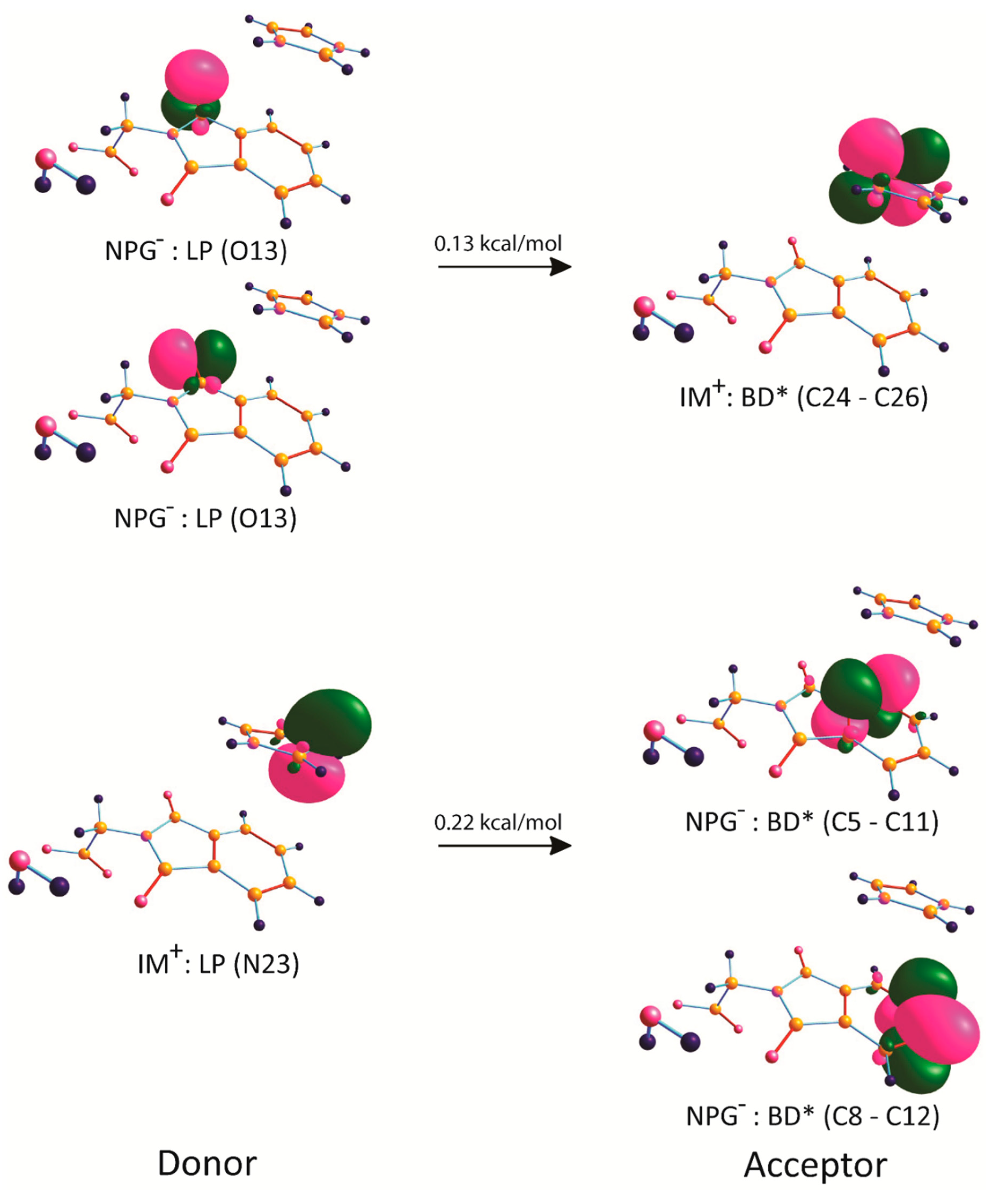
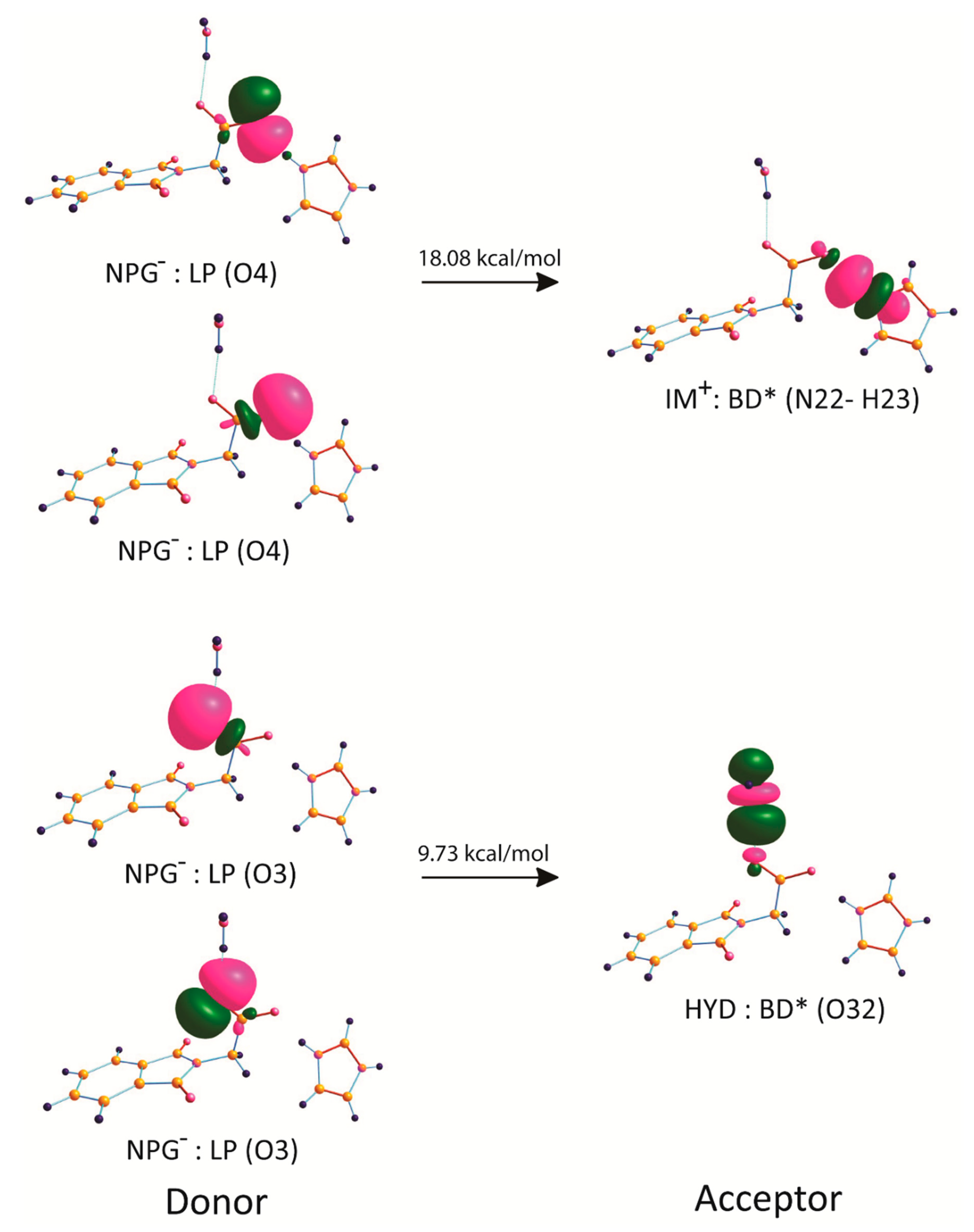
2.6. Natural Bond Orbital Analysis

The NBO analysis was carried out to investigate the role of charge transfer in the charge-assisted hydrogen bond and π···π stacking interaction using the second-order perturbation theory of the Fock matrix within the framework of natural bond orbital (NBO) analysis. From the NBO analysis, the strength of the CT donor-acceptor interactions between NPG and IM+ or H2O in IM+–NPG–HYD can be obtained by probing the interactions between the filled (i, donor) Lewis-type NBOs and empty (j, acceptor) non-Lewis-type NBOs. In configuration A, both the NPG and IM+ fragments behave as a donor and also as an acceptor. In addition, the charge transferred from the donor: NPG to the acceptor: IM+ and vice versa are attributed to the weak non-classical O···C and N···C contacts, respectively. This CT mainly derives from the lone electron pairs of both oxygen and nitrogen in NPG and IM+, respectively, along with the empty antibonding orbitals of the carbon of the acceptor fragment. The energies of these interactions E(2) and donor-acceptor NBO orbital pairs are presented in Table 5 and Figure 11 and Figure 12. Such behavior indicates that the charge facilitates the whole supramolecular assembly along the crystallographic molecular axis. While in configuration B, the CT resulting from the charge-assisted hydrogen bond is mainly attributed to the electron-donor (NPG) and electron-acceptor (IM+) interactions of the lone pair electrons of oxygen (from the carboxylate group) of NPG with an empty antibonding orbitals of the hydrogen-bonding donor hydrogen atom of IM+ LP(O) to BD* (D–H).

3. Conclusions

An organic supramolecular salt hydrate (imidazolium:N-phthalolylglycinate:H2O; IM+–NPG–HYD) has been synthesized and characterized by single X-ray crystallography, 1H NMR, IR, tandem mass-spectroscopy (ESI-MS/MS), elemental analysis, and UV–vis spectroscopy. The IM+–NPG–HYD crystallizes in the monoclinic space group C2/c (Z = 8). The IM+–NPG–HYD salt hydrate was formed via supramolecular self-assembly. The mixed π–π stacking donor-acceptor interactions and charge-assisted hydrogen-bonding interactions between IM+ and NPG are the primary driving intermolecular interactions for the self-assembly, and they contribute to the CT characteristics of IM+–NPG–HYD. The nature of the anion-to-cation CT was confirmed by comparing UV–vis spectra of IM and NPG, new absorption broadband ranging from 350 to 550 nm has appeared in IM+–NPG–HYD, corresponds to the CT band, confirms the formation of donor-acceptor CT IM+–NPG–HYD.
A series of DFT calculations have been performed to reproducing the experimental results. The DFT calculated structures and 1H NMR spectrum are in good agreement with experimental results. The TDDFT calculated UV–vis spectrum reproduced major spectral features observed in the experimentally recorded spectrum. Also, electron-hole and Hirshfeld charge analysis validated the charge transfer (CT) nature of salt hydrate. Furthermore, the Hirshfeld surface, QTAIM, and NBO analysis explored the nature and strength of non-covalent interaction and their role in the charge transfer phenomenon.

4. Experimental Section

4.1. General Methods and Instrumentation

All the starting materials were purchased from well-known chemical suppliers (Sigma-Aldrich St. Louis, MO, USA) and were used without further purification. The solvents used were of analytical or chromatographic grade.
The infrared spectra were obtained (KBr disk, 400–4000 cm1) on a Perkin–Elmer Model 1320 spectrometer (Waltham, MA, USA). The electronic spectrum was recorded on PerkinElmer UV–vis spectrophotometer (Waltham, MA, USA). The NMR spectra were obtained on a Bruker DRX−400 spectrometer (Billerica, MA, USA) with Me2SO−d6 as the solvent.

4.2. Synthesis of IM+–NPG–HYD (1:1:1)

A total of 333 mg (2 mmol) of NPG and 104 mg (2.0 mmol) of IM were milled with 5–10 drops of aqueous methanolic solution for 30 min at room temperature, and salt formation was confirmed using the IR, NMR, and ESI techniques. Then, the compound (50 mg) was dissolved in an aqueous solution of methanol and left to evaporate slowly at room temperature. Good-quality crystals suitable for single-crystal X-ray crystallography analysis were obtained after 15 days.
M.p. 154 °C. Anal. cal. for C13H13N3O5 (%): C, 53.61; H, 4.50; N, 14.43. Anal. found: C, 53. 65; H, 4.58; N, 14.44. FT IR (KBr, νmax/cm–1): 3310 ν(OH); 3173 ν(N–H); 2934 ν(-CH2); 1708 νasym (COO); 1420 νsym (COO). 1H NMR (400 MHz, DMSO-d6, δ, ppm): 4.31 (-CH2), 7.85–7.93 (m, Ar–H, NPG), 7.01–7.64 (Ar–H, IM+), 11.90 (-NH). UV–vis (1×10³ M, EtOH, nm): 260, 300, 350–550. ESI-MS/MS (m/z): 294.1 [C13H13N3O5 + 3H+].

4.3. Single-Crystal X-ray Crystallography

A Bruker SMART APEX CCD diffractometer (Billerica, MO, USA) was used to collect the single-crystal X-ray data at 100 K by employing graphite monochromatic MoK radiation (0.71073). The linear absorption coefficient, scattering factors for the atoms, and anomalous dispersion correction were referred from the International Table for X-ray crystallography [59]. The data integration and reduction were performed using SAINT software [60]. Empirical absorption correction was applied to collected reflections by using SADABS [61], and the space group was determined using XPREP [62].
The structure was solved via direct methods using SHELXTL-2016 and refined on F via full-matrix least-squares using the SIR-97 program package [63]. Only a few H atoms could be located in the difference Fourier maps of the structure. The positions of the remaining were calculated using idealized geometries (riding model) and assigned fixed isotropic displacement parameters. All the non-H atoms were refined anisotropically. The structure-refinement and crystal data are presented in Table 6. The selective bond distance and angles are presented in Tables S1 and S2, respectively.
.

5. Computational Details

The single-point calculation, full geometry optimization, and NBO analysis [64] were performed at DFT level of theory by using the M06-2X functional [65] (this functional was specifically developed to describe weak dispersion forces and noncovalent interactions) with the help of the Gaussian-09 program package [66]. The calculations were performed using cc-pVTZ basis sets [67] for all the atoms. All the geometry optimizations and TDDFT calculations were performed by employing the polarizable continuum model, CPCM (EtOH as solvent). No symmetry restrictions were applied during geometry optimization. Furthermore, the Hessian matrix was calculated analytically for the optimized structures to prove the location of the correct minima (no imaginary frequencies). The 1H NMR spectrum of IM+–NPG–HYD salt hydrated simulated using DFT/B3LYP/6-311+G(2d,p) and PBE0/Def2-TZVPP methods [68,69]. We have simulated the UV–vis spectrum (vertical excitation energies and oscillator strengths) of IM+–NPG–HYD using the CAM-B3LYP/cc-pVTZ method. The CAM-B3LYP functional is working well to calculate CT excitations by adopting the Coulomb-attenuating method as long-range corrected modification [70]. The electron–hole distribution, charge density difference (CDD), and inter-fragment CT analysis between the singlet ground state (S0) and singlet excited states (Sn, where n = 1–20) have been carried out with Multiwfn program [58] on the time-dependent wavefunction solution of IM+–NPG–HYD generated at the CAM-B3LYP/cc-pVTZ level of theory. In addition to the topological analysis of the electron-density distribution by using the QTAIM and ELF method, it has been performed employing the Multiwfn program. The Hirshfeld surface was mapped using Crystal Explorer [71] software using crystal structure coordinates of CIF files. The Cartesian atomic coordinates of the calculated equilibrium structures in ethanol are provided in the ESI-material.

Supplementary Materials

The following are available online at https://www.mdpi.com/2073-4352/10/2/91/s1, Figure S1: IR spectra of solid polycrystalline samples of imidazole (Purple), NPG (Blue) and IM+–NPG–HYD (Red); Figure S2: DFT/M062X/6-31G** simulated IR spectrum of IM+–NPG–HYD; Figure S3: ESI-MS spectrum of polycrystalline samples of IM+–NPG–HYD; Figure S4: Diagram illustrating the packing of IM+–NPG–HYD in the unit cell at 100 K (H atoms have been omitted for clarity); Figure S5: DFT optimized structures in EtOH of both the configuration (a) A and (b) B of the IM+–NPG–HYD at the M062X/6-31G** level of theory. Bond distances given in angstrom (Å); Figure S6: Hirshfeld surface mapped with dnorm (left), shape index (middle), and curvedness (right) for the IM+–NPG–HYD; Figure S7: QTAIM analysis of N···C, and O···O interactions in IM+–NPG–HYD (configuration A): (a) contour line plots of the electron density ρ, (b) contour line plots of the Laplacian distribution of electron density ∇2ρ(r), the solid (red) and dashed (blue) lines corresponds to positive and negative values of ∇2ρ(r) respectively, (c) surface maps of electron localization function (ELF), and (d) NCI surface between IM+ and NPG showing electron density for π-π stacking interaction. Bond paths are shown as black lines, selected zero-flux surfaces, bond critical points, and BCPs, (3, −1) are shown in blue; Figure S8: Showing charge transfer donor-acceptor moieties of both the configuration (a) A and (b) B of the IM+–NPG–HYD. Pink arrow represents the dipole moment vector; Figure S9: Electron (green isosurface) and hole (blue isosurface) distribution between excited state and ground state of IM+–NPG–HYD for the absorptions at 297, 336, 427, and 443 nm. Value of contour envelopes is 0.002 au; Figure S10: Electron (green isosurface) and hole (blue isosurface) distribution between excited state and ground state of IM+–NPG–HYD for the absorptions at 510, 530, 427, and 652 nm. Value of contour envelopes is 0.002 au; Table S1: Bond Lengths in Å for IM+–NPG–HYD; Table S2: Bond Angles for IM+–NPG–HYD; Table S3: Atomic Hirshfeld and atomic dipole moment1 (ADC) corrected charges for IM+–NPG–HYD; Table S4: TD-DFT calculation for IM+–NPG–HYD at the CAM-B3LYP/cc-PVTZ theoretical level; calculated wavelength (λ), oscillator strength (f), transition energy (E), and contributing orbitals to the transitions.

Author Contributions

Conceptualization, M.U. and R.A.K.; methodology, M.U. and R.A.K.; software, M.U.; validation, M.U., R.A.K., A.A. and S.T.; formal analysis, M.U., R.A.K., M.H.J., A.A. and S.T.; investigation, M.U., R.A.K., M.H.J., A.A. and S.T.; resources, R.A.K., M.H.J., A.A.; data curation, M.U.; writing—original draft preparation, M.U., R.A.K.; writing—review and editing, M.U., R.A.K., M.H.J., A.A. and S.T.; visualization, X.X.; supervision, R.A.K. and S.T.; project administration, A.A. and R.A.K.; funding acquisition, A.A. and R.A.K. All authors have read and agreed to the published version of the manuscript.

Funding

The authors are grateful to the Researchers Supporting Project number (RSP-2019/78), King Saud University, Riyadh, Saudi Arabia.

Conflicts of Interest

The authors declare no conflict of interest. The funders had no role in the design of the study; in the collection, analyses, or interpretation of data; in the writing of the manuscript, or in the decision to publish the results.

References

  1. Whitesides, G.M.; Mathias, J.P.; Seto, C.T. Molecular self-assembly and nanochemistry: A chemical strategy for the synthesis of nanostructures. Science 1991, 254, 1312–1319. [Google Scholar] [CrossRef]
  2. Lehn, J.M. From supramolecular chemistry towards constitutional dynamic chemistry and adaptive chemistry. Chem. Soc. Rev. 2007, 36, 151–160. [Google Scholar] [CrossRef]
  3. Desiraju, G.R.; Parshall, G.W. Crystal Engineering: The Design of Organic. Solids. Mater. Sci. Monogr. 1989, 54. [Google Scholar]
  4. Biradha, K. Crystal engineering: From weak hydrogen bonds to co-ordination bonds. CrystEngComm 2003, 5, 374–384. [Google Scholar] [CrossRef]
  5. Xie, Z.; Yang, B.; Li, F.; Cheng, G.; Liu, L.; Yang, G.; Xu, H.; Ye, L.; Hanif, M.; Liu, S.; et al. Cross Dipole Stacking in the Crystal of Distyrylbenzene Derivative:  The Approach toward High Solid-State Luminescence Efficiency. J. Am. Chem. Soc. 2005, 127, 14152–14153. [Google Scholar] [CrossRef] [PubMed]
  6. Fang, X.; Yang, X.; Yan, D.J. Vapor-phase π–π molecular recognition: A fast and solvent-free strategy towards the formation of co-crystalline hollow microtube with 1D optical waveguide and up-conversion emission. J. Mater. Chem. C 2017, 5, 1632–1637. [Google Scholar] [CrossRef]
  7. Yan, D.P.; Delori, A.; Lloyd, G.O.; Friscic, T.; Day, G.M.; Jones, W.; Lu, J.; Wei, M.; Evans, D.G.; Duan, X. A cocrystal strategy to tune the luminescent properties of stilbene-type organic solid-state materials. Angew. Chem. Int. Ed. 2011, 50, 12483–12486. [Google Scholar] [CrossRef]
  8. Chung, J.W.; You, Y.; Huh, H.S.; An, B.-K.; Yoon, S.-J.; Kim, S.H.; Lee, S.W.; Park, S.Y.J. Shear-and UV-induced fluorescence switching in stilbenic π-dimer crystals powered by reversible [2 + 2] cycloaddition. Am. Chem. Soc. 2009, 131, 8163–8172. [Google Scholar] [CrossRef]
  9. Qin, Y.; Zhang, J.; Zheng, X.; Geng, H.; Zhao, G.; Xu, W.; Hu, W.; Shuai, Z.; Zhu, D. Charge-Transfer Complex Crystal Based on Extended-π-Conjugated Acceptor and Sulfur-Bridged Annulene: Charge-Transfer Interaction and Remarkable High Ambipolar Transport Characteristics. Adv. Mater. 2014, 26, 4093–4099. [Google Scholar] [CrossRef]
  10. Zhang, J.; Tan, J.H.; Ma, Z.Y.; Xu, W.; Zhao, G.Y.; Geng, H.; Di, C.A.; Hu, W.P.; Shuai, Z.G.; Singh, K.; et al. Fullerene/sulfur-bridged annulene cocrystals: Two-dimensional segregated heterojunctions with ambipolar transport properties and photoresponsivity. J. Am. Chem. Soc. 2013, 135, 558–561. [Google Scholar] [CrossRef]
  11. Zhang, J.; Geng, H.; Virk, T.S.; Zhao, Y.; Tan, J.H.; Di, C.A.; Xu, W.; Singh, K.; Hu, W.P.; Shuai, Z.G.; et al. Sulfur-Bridged Annulene-TCNQ Co-Crystal: A Self-Assembled ‘‘Molecular Level Heterojunction’’ with Air Stable Ambipolar Charge Transport Behavior. Adv. Mater. 2012, 24, 2603–2607. [Google Scholar] [CrossRef] [PubMed]
  12. Kang, S.J.; Ahn, S.; Kim, J.B.; Schenck, C.; Hiszpanski, A.M.; Oh, S.; Schiros, T.; Loo, Y.-L.; Nuckolls, C. Using self-organization to control morphology in molecular photovoltaics. J. Am. Chem. Soc. 2013, 135, 2207–2212. [Google Scholar] [CrossRef] [PubMed]
  13. Wuest, J.D. Co-crystals give light a tune-up. Nat. Chem. 2012, 4, 74–75. [Google Scholar] [CrossRef] [PubMed]
  14. Yan, D.; Yang, H.; Meng, Q.; Lin, H.; Wei, M. Two-Component Molecular Materials of 2,5-Diphenyloxazole Exhibiting Tunable Ultraviolet/Blue Polarized Emission, Pump-enhanced Luminescence, and Mechanochromic Response. Adv. Funct. Mater. 2014, 24, 587–594. [Google Scholar] [CrossRef]
  15. Tsutsumi, J.Y.; Yamada, T.; Matsui, H.; Haas, S.; Hasegawa, T. Competition between charge-transfer exciton dissociation and direct photocarrier generation in molecular donor-acceptor compounds. Phys. Rev. Lett. 2010, 105, 226601. [Google Scholar] [CrossRef] [PubMed]
  16. Vincent, V.M.; Wright, J.D. Competition between charge-transfer exciton dissociation and direct photocarrier generation in molecular donor-acceptor compounds. J. Chem. Soc. Faraday Trans. 1974, 70, 58–71. [Google Scholar] [CrossRef]
  17. Horiuchi, S.; Ishii, F.; Kumai, R.; Okimoto, Y.; Tachibana, H.; Nagaosa, N.; Tokura, Y. Ferroelectricity near room temperature in co-crystals of nonpolar organic molecules. Nat. Mater. 2005, 4, 163–166. [Google Scholar] [CrossRef]
  18. Tayi, A.S.; Shveyd, A.K.; Sue, A.C.H.; Szarko, J.M.; Rolczynski, B.S.; Cao, D.; Kennedy, T.J.; Sarjeant, A.A.; Stern, C.L.; Paxton, W.F.; et al. Room-temperature ferroelectricity in supramolecular networks of charge-transfer complexes. Nature 2012, 488, 485–489. [Google Scholar] [CrossRef]
  19. Bosshard, C.; Wong, M.S.; Pan, F.; Gunter, P.; Gramlich, V. Self-assembly of an acentric co-crystal of a highly hyperpolarizable merocyanine dye with optimized alignment for nonlinear optics. Adv. Mater. 1997, 9, 554–557. [Google Scholar] [CrossRef]
  20. Pan, F.; Wong, M.S.; Gramlich, V.; Bosshard, C.; Gunter, P.J. A Novel and Perfectly Aligned Highly Electro—Optic Organic Cocrystal of a Merocyanine Dye and 2,4-Dihydroxybenzaldehyde. J. Am. Chem. Soc. 1996, 118, 6315–6316. [Google Scholar] [CrossRef]
  21. Morimoto, M.; Irie, M. A diarylethene cocrystal that converts light into mechanical work. J. Am. Chem. Soc. 2010, 132, 14172–14178. [Google Scholar] [CrossRef] [PubMed]
  22. Braga, D.; Maini, L.; Grepioni, F. Mechanochemical preparation of co-crystals. Chem. Soc. Rev. 2013, 42, 7638–7648. [Google Scholar] [CrossRef] [PubMed]
  23. Shimozawa, M.; Hashimoto, K.; Ueda, A.; Suzuki, Y.; Sugii, K.; Yamada, S.; Imai, Y.; Kobayashi, R.; Itoh, K.; Iguchi, S.; et al. Quantum-disordered state of magnetic and electric dipoles in an organic Mott system. Nat. Commun. 2017, 8, 1–6. [Google Scholar] [CrossRef] [Green Version]
  24. Ueda, A.; Yamada, S.; Isono, T.; Kamo, H.; Nakao, A.; Kumai, R.; Nakao, H.; Murakami, Y.; Yamamoto, K.; Nishio, Y.; et al. Hydrogen-bond-dynamics-based switching of conductivity and magnetism: A phase transition caused by deuterium and electron transfer in a hydrogen-bonded purely organic conductor crystal. J. Am. Chem. Soc. 2014, 136, 12184–12192. [Google Scholar] [CrossRef] [PubMed]
  25. Ueda, A.; Hatakeyama, A.; Enomoto, M.; Kumai, R.; Murakami, Y.; Mori, H. Modulation of a Molecular π-Electron System in a Purely Organic Conductor that Shows Hydrogen-Bond-Dynamics-Based Switching of Conductivity and Magnetism. Chem. Eur. J. 2015, 21, 15020–15028. [Google Scholar] [CrossRef] [PubMed]
  26. Collini, E. Cooperative effects to enhance two-photon absorption efficiency: Intra-versus inter-molecular approach. Phys. Chem. Chem. Phys. 2012, 14, 3725–3736. [Google Scholar] [CrossRef]
  27. Ono, T.; Sugimoto, M.; Hisaeda, Y. Multicomponent Molecular Puzzles for Photofunction Design: Emission Color Variation in Lewis Acid–Base Pair Crystals Coupled with Guest-to-Host Charge Transfer Excitation. J. Am. Chem. Soc. 2015, 137, 9519–9522. [Google Scholar] [CrossRef]
  28. Narayanan, A.; Cao, D.; Frazer, L.; Tayi, A.S.; Blackburn, A.K.; Sue, A.C.-H.; Ketterson, J.B.; Stoddart, J.F.; Stupp, S.I. Ferroelectric Polarization and Second Harmonic Generation in Supramolecular Cocrystals with Two Axes of Charge-Transfer. J. Am. Chem. Soc. 2017, 139, 9186–9191. [Google Scholar] [CrossRef]
  29. Zhu, W.; Zheng, R.; Fu, X.; Fu, H.; Shi, Q.; Zhen, Y.; Dong, H.; Hu, W. Revealing the Charge-Transfer Interactions in Self-Assembled Organic Cocrystals: Two-Dimensional Photonic Applications. Angew. Chem. Int. Ed. 2015, 54, 6785–6789. [Google Scholar] [CrossRef]
  30. Mulliken, R.S. Molecular compounds and their spectra. II. J. Am. Chem. Soc. 1952, 74, 811–824. [Google Scholar] [CrossRef]
  31. Thomas, L.H.; Jones, A.O.F.; Kallay, A.A.; McIntyre, G.J.; Wilson, C.C. Engineering short, strong, charge-assisted hydrogen bonds in benzoic acid dimers through cocrystallization with proton sponge. Cryst. Growth Des. 2016, 16, 2112–2122. [Google Scholar] [CrossRef] [Green Version]
  32. Ward, M.D. Design of crystalline molecular networks with charge-assisted hydrogen bonds. Chem. Commun. 2005, 47, 5838–5842. [Google Scholar] [CrossRef] [PubMed]
  33. Braga, D.; Grepioni, F. Intermolecular interactions in nonorganic crystal engineering. Acc. Chem. Res. 2000, 33, 601–608. [Google Scholar] [CrossRef] [PubMed]
  34. Aaker€oy, C.B.; Beatty, A.M.; Lorimer, K.R. Charge-assisted hydrogen bonds and halogen-halogen interactions in organic salts: Benzylammonium benzoates and pentafluorobenzoates. Struct. Chem. 1999, 10, 229–242. [Google Scholar] [CrossRef]
  35. Braga, D.; Draper, S.M.; Champeil, E.; Grepioni, F. Inorganic–organometallic crystal synthesis. The role of charge-assisted C–H…O and C–H…Cl hydrogen bonds in crystalline [(η5-C5H5) 2Co][H2PO4]· 3H2O and [(η6-C6H5Me) 2Cr][Cl]. J. Organomet. Chem. 1999, 573, 73–77. [Google Scholar] [CrossRef]
  36. Bankiewicz, B.; Matczak, P.; Palusiak, M. Electron density characteristics in bond critical point (QTAIM) versus interaction energy components (SAPT): The case of charge-assisted hydrogen bonding. J. Phys. Chem. A 2012, 116, 452–459. [Google Scholar] [CrossRef]
  37. Matczak, P. Intramolecular C–H···H–C contacts in diheteroaryl ketones and thioketones: A theoretical analysis. Bull. Chem. Soc. Jpn. 2016, 89, 92–102. [Google Scholar] [CrossRef]
  38. Silverstein, R.M.; Silverstein, G.C. Bassler Spectrometric Identification of Organic Compounds. J. Chem. Educ. 1962, 39, 546. [Google Scholar] [CrossRef]
  39. Ganduri, R.; Swain, D.; Cherukuvada, S.; Row, T.N.G. Role of functionalities in structural analogues urocanic acid and l-histidine, toward the formation of anhydrous and hydrated molecular salts. Cryst. Growth Des. 2019, 19, 1845–1852. [Google Scholar] [CrossRef]
  40. Gunnam, A.; Suresh, K.; Nangia, A. Salts and salt cocrystals of the antibacterial drug pefloxacin. Cryst. Growth Des. 2018, 18, 2824–2835. [Google Scholar] [CrossRef]
  41. Oomens, J.; Steill, J.D. Free carboxylate stretching modes. J. Phys. Chem. 2008, 112, 3281–3283. [Google Scholar] [CrossRef] [PubMed]
  42. Steill, J.D.; Oomens, J. Gas-phase deprotonation of p-hydroxybenzoic acid investigated by IR spectroscopy: Solution-phase structure is retained upon ESI. J. Am. Chem. Soc. 2009, 131, 13570–13571. [Google Scholar] [CrossRef] [PubMed]
  43. Arenas-García, J.R.; Ruiz, D.H.; Vasquez, K.M.; Rojas, H.M.; Hopfl, H. Modification of the supramolecular hydrogen-bonding patterns of acetazolamide in the presence of different cocrystal formers: 3:1, 2:1, 1:1, and 1:2 cocrystals from screening with the structural isomers of hydroxybenzoic acids, aminobenzoic acids, hydroxybenzamides, aminobenzamides, nicotinic acids, nicotinamides, and 2, 3-dihydroxybenzoic acids. Cryst. Growth Des. 2012, 12, 811–824. [Google Scholar]
  44. Gao, L.; Zhang, X.-R.; Chen, Y.-F.; Liao, Z.-L.; Wang, Y.-Q.; Zou, X.-Y. A new febuxostat imidazolium salt hydrate: Synthesis, crystal structure, solubility, and dissolution study. J. Mol. Struct. 2019, 1176, 633–640. [Google Scholar] [CrossRef]
  45. Mandal, A.; Rissanen, K.; Mal, P. Unravelling substitution effects on charge transfer characteristics in cocrystals of pyrene based donors and 3, 5-dinitrobenzoic acid. CrystEngComm 2019, 21, 4401–4408. [Google Scholar] [CrossRef]
  46. Mandal, A.; Swain, P.; Nath, B.; Sau, S.; Mal, P. Unipolar to ambipolar semiconductivity switching in charge transfer cocrystals of 2, 7-di-tert-butylpyrene. CrystEngComm 2019, 21, 981–989. [Google Scholar] [CrossRef]
  47. Usman, R.; Khan, A.; Wang, M.; Luo, Y.; Sun, W.; Sun, H.; Du, C.; He, N. Investigation of charge-transfer interaction in mixed stack donor–acceptor cocrystals toward tunable solid-state emission characteristics. Cryst. Growth Des. 2018, 18, 6001–6008. [Google Scholar] [CrossRef]
  48. Zhu, W.; Zheng, R.; Zhen, Y.; Yu, Z.; Dong, H.; Fu, H.; Shi, Q.; Hu, W. Rational design of charge-transfer interactions in halogen-bonded co-crystals toward versatile solid-state optoelectronics. J. Am. Chem. Soc. 2015, 137, 11038–11046. [Google Scholar] [CrossRef]
  49. Bader, R. Atoms in Molecules; Oxford University Press: Oxford, UK, 1994; Available online: https://global.oup.com/academic/product/atoms-in-molecules-9780198558651?cc=sa&lang=en& (accessed on 5 February 2020).
  50. Bader, R.F.W. A quantum theory of molecular structure and its applications. Chem. Rev. 1991, 91, 893–928. [Google Scholar] [CrossRef]
  51. Koch, U.; Popelier, P. Characterization of CHO hydrogen bonds on the basis of the charge density. J. Phys. Chem. A 1995, 99, 9747–9754. [Google Scholar] [CrossRef]
  52. Rozas, I.; Alkorta, I.; Elguero, J. Behavior of ylides containing N, O, and C atoms as hydrogen bond acceptors. J. Am. Chem. Soc. 2000, 122, 11154–11161. [Google Scholar] [CrossRef]
  53. Espinosa, E.; Alkorta, I.; Elguero, J.; Molins, E. From weak to strong interactions: A comprehensive analysis of the topological and energetic properties of the electron density distribution involving X–H⋯F–Y systems. J. Chem. Phys. 2002, 117, 5529–5542. [Google Scholar] [CrossRef]
  54. Espinosa, E.; Molins, E.; Lecomte, C. Hydrogen bond strengths revealed by topological analyses of experimentally observed electron densities. Chem. Phys. Lett. 1998, 285, 170–173. [Google Scholar] [CrossRef]
  55. Vener, M.V.; Egorova, A.N.; Churakov, A.V.; Tsirelson, V.G. Intermolecular hydrogen bond energies in crystals evaluated using electron density properties: DFT computations with periodic boundary conditions. J. Comput. Chem. 2012, 33, 2303–2309. [Google Scholar] [CrossRef] [PubMed]
  56. Park, S.K.; Varghese, S.; Kim, J.H.; Yoon, S.-J.; Kwon, O.K.; An, B.-K.; Gierschner, J.; Park, S.Y. Tailor-made highly luminescent and ambipolar transporting organic mixed stacked charge-transfer crystals: An isometric donor–acceptor approach. J. Am. Chem. Soc. 2013, 135, 4757–4764. [Google Scholar] [CrossRef] [PubMed]
  57. Zhu, L.; Yi, Y.; Li, Y.; Kim, E.-G.; Coropceanu, V.; Brédas, J.-L. Prediction of remarkable ambipolar charge-transport characteristics in organic mixed-stack charge-transfer crystals. J. Am. Chem. Soc. 2012, 134, 2340–2347. [Google Scholar] [CrossRef] [PubMed]
  58. Lu, T.; Chen, F.-W. Multiwfn: A multifunctional wavefunction analyzer. J. Comput. Chem. 2012, 33, 580–592. [Google Scholar] [CrossRef] [PubMed]
  59. Cromer, D.T.; Waber, J.T. International Tables for X-Ray Crystallography, Kynoch. Birm. Engl. 1952, 3, 257–269. [Google Scholar]
  60. Sheldrick, G.M. SAINT (Version 6.02), SADABS (Version 2.03); Bruker AXS: Madison, WI, USA, 2002. [Google Scholar]
  61. Sheldrick, G.M. SADABS, Program for Empirical Absorption Correction of Area Detector Data. Available online: https://www.scienceopen.com/document?vid=5cab3651-c60c-4e6d-89cc-c55396e9e2dc (accessed on 5 February 2020).
  62. Sheldrick, G.M. SAINT and XPREP, version 5.1; Siemens Industrial Automation Inc.: Madison, WI, USA, 1995. [Google Scholar]
  63. Sheldrick, G.M. SHELXTL, version 5.1; Bruker Analytical X-ray Instruments Inc.: Madison, WI, USA, 1998; Volume 4, p. 18. [Google Scholar]
  64. Glendening, E.D.; Reed, A.E.; Carpenter, J.E.; Weinhold, F. Gaussian 09 Citation; Gaussian. Inc.: Wallingford, CT, USA, 2009. [Google Scholar]
  65. Zhao, Y.; Truhlar, D.G. The M06 suite of density functionals for main group thermochemistry, thermochemical kinetics, noncovalent interactions, excited states, and transition elements: Two new functionals and systematic testing of four M06-class functionals and 12 other functionals. Theor. Chem. Acc. 2008, 120, 215–241. [Google Scholar]
  66. Frisch, M.J.T.; Trucks, G.W.; Schlegel, H.B.; Scuseria, G.E.; Robb, M.A.C.; Cheeseman, J.R.; Scalmani, G.; Barone, V.; Mennucci, G.A.N.B.; Petersson, H.; et al. Gaussian 09 Citation. Available online: https://gaussian.com/g09citation/ (accessed on 5 February 2020).
  67. Dunning, T.H., Jr. Gaussian basis sets for use in correlated molecular calculations. I. The atoms boron through neon and hydrogen. J. Chem. Phys. 1989, 90, 1007. [Google Scholar] [CrossRef]
  68. Adamo, C.; Scuseria, G.E.; Barone, V. Accurate excitation energies from time-dependent density functional theory: Assessing the PBE0 model. J. Chem. Phys. 1999, 111, 2889. [Google Scholar] [CrossRef]
  69. Flaig, D.; Maurer, M.; Hanni, M.; Braunger, K.; Kick, L.; Thubauville, M.; Ochsenfeld, C. Benchmarking hydrogen and carbon NMR chemical shifts at HF, DFT, and MP2 levels. J. Chem. Theory Comput. 2014, 10, 572–578. [Google Scholar] [CrossRef] [PubMed]
  70. Yanai, T.; Tew, D.P.; Handy, N.C. A new hybrid exchange–correlation functional using the Coulomb-attenuating method (CAM-B3LYP). Chem. Phys. Lett. 2004, 393, 51–57. [Google Scholar] [CrossRef] [Green Version]
  71. Spackman, M.A.; Jayatilaka, D. Hirshfeld surface analysis. CrystEngComm. 2009, 11, 19–32. [Google Scholar] [CrossRef]
Figure 1. Absorption spectra (curved line, left axis) of IM, NPG, and IM+–NPG–HYD in EtOH (1 × 10⁻⁴ M) and oscillator strengths (vertical line, right axis) obtained from TD-DFT calculations at the cam-B3LYP/cc-pVTZ level of theory. The expanded view of experimentally observed broad CT- band (350–550 nm) in IM+–NPG–HYD is depicted in the right upper corner.
Crystals 10 00091 g001
Figure 2. 1H NMR spectra (in d6-DMSO at 295 K) of (a) IM, (b) NPG, and (c) IM+–NPG–HYD. The DFT calculated chemical shielding (ppm) for IM+–NPG–HYD protons are shown in blue and red vertical lines.
Crystals 10 00091 g002
Figure 3. Crystal structure with the label of IM+–NPG–HYD.
Crystals 10 00091 g003
Figure 4. Two different configurations of IM+–NPG–HYD in the supramolecular assembly: (a) A and (b) B. Distances of π–π stacking and hydrogen bonds are in angstrom, and the green line depicts the hydrogen bonds. The interfragmentary interaction energy between each IM+, NPG, and H2O moieties is calculated via Hirshfeld charge analysis.
Crystals 10 00091 g004
Figure 5. Supramolecular assembly of IM+–NPG–HYD along different crystallographic axes (a) a-axis, (b) mixed stacking donor-acceptor columns connected to water through hydrogen bonds, and (c) configurations A and B crystallized within the framework of supramolecular assembly.
Crystals 10 00091 g005
Figure 6. Fingerprint plots of cation and anion of IM+–NPG–HYD, (a) IM+, and (b) NPG: full (upper left) and resolved into different intermolecular interactions showing the percentages of interactions contributing to the total Hirshfeld surface area of the cation and anion in the salt hydrate. The x-axis and y-axis represent the values of de (distance from the point to the nearest nucleus external to the surface) and di (distance to the nearest nucleus internal to the surface).
Crystals 10 00091 g006
Figure 7. QTAIM-analysis-based molecular graph of two different configurations of IM+–NPG–HYD: (a) A and (b) B, both showing the BP and electron density (ρ) computed at bond critical points (BCPs). Orange circles indicate the BCPs.
Crystals 10 00091 g007
Figure 8. QTAIM analysis of charge-assisted hydrogen-bonding interactions in IM+–NPG–HYD (for configuration A). (a) Contour-line plots of the electron density ρ. (b) Contour-line plots of the Laplacian distribution of electron density ∇2ρ(r), where the solid (red) and dashed (blue) lines correspond to the positive and negative values of ∇2ρ(r), respectively. (c) Surface maps of ELF. (d) Counter-line map of the electrostatic surface potential (ESP), where the solid (red) and dashed (blue) lines correspond to the positive and negative values of ESP, respectively. BPs are shown as black lines, the selected zero-flux surfaces, or interbasin paths as blue lines, and BCPs (3, –1) are shown in blue.
Crystals 10 00091 g008
Figure 9. Energy diagrams and Kohn–Sham orbitals of IM, NPG, and IM+–NPG–HYD (configurations A and B). The value of contour envelopes is 0.03 a.u.
Crystals 10 00091 g009
Figure 10. CDD and the extent of inter-fragment CT between the excited state and the ground state of IM+–NPG–HYD for the absorptions at 259, 297, 298, and 446 nm. Blue and green surfaces represent the accumulation and diminution of charge concentration during excitation. The value of contour envelopes is 0.002 a.u.
Crystals 10 00091 g010
Figure 11. LP → BD* donor-acceptor orbitals’ interaction derived from the NBO analysis of IM+–NPG–HYD (for configuration A). Hydrogen atoms are omitted for clarity (isovalue = 0.03).
Crystals 10 00091 g011
Figure 12. LP → BD* donor-acceptor orbitals’ interaction derived from the NBO analysis of IM+–NPG–HYD (for configuration A). Hydrogen atoms are omitted for clarity (isovalue = 0.03).
Crystals 10 00091 g012
Table 1. Some selected experimental and calculated frequencies (cm−1) of IM+–NPG–HYD salt.
Vibrational ModeExperimentalCalculated
νsv(-OH)3502.273636
νsv(-NH)3410.163502
νsv(-CH)3173.103249
νsv(-CH2)2934.583007
νsv(-C=O)1774.591745
νav(-O-C=O)1708.601710
νsv(-O-C=O)1419.981426
sν, symmetrical stretching; aν, anti-symmetrical stretching.
Table 2. Single-crystal X-ray determined, and DFT calculated bond Lengths in Å for IM+-NPG ̶ -HYD.
BondDFTX-rayBondDFTX-ray
Conf. AConf. B Conf. AConf. B
O1-C11.209111.207741.207(3)C1-C21.493321.491951.487(3)
O2-C81.216261.208171.213(3)C2-C31.383891.382601.384(3)
O3-C101.248041.228231.243(3)C2-C71.390691.390561.386(3)
O4-C101.250071.289721.264(3)C3-C41.398781.398311.391(4)
N1-C11.386061.400231.392(3)C4-C51.398231.396551.391(4)
N1-C81.400311.398451.381(3)C5-C61.398971.396941.392(4)
N1-C91.449651.438141.448(3)C6-C71.383461.383241.374(4)
N2-C111.378021.375841.373(3)C7-C81.493681.491641.497(3)
N2-C131.32984 1.321551.325(3)C9-C101.562291.538191.526(4)
N3-C121.376841.372681.370(3)C11-C121.359691.364191.344(4)
N3-C131.328691.342071.322(3)
IM+··· NPG ̶3.23483 3.359(3)
IM+··· NPG ̶ 2.456622.665(3)
Table 3. Hydrogen bonds in IM+–NPG–HYD.
D–H···AD···A (Å)H···A (Å)D–H···A (deg)Symmetry Code
O1W–H1···O22.9249(5)2.13152
N2–H2···O42.6577(4)1.81167½ − x,1/2 − y,1 − z
O1W–H1···O32.7059(5)1.84173
N3–H3A···O1W2.7525(5)1.98150
C3–H3···O13.3427(6)2.47157x,1 − y,1/2 + z
C9–H9A···O13.4578(6)2.51164½ − x, − ½ + y,1/2 − z
C11–H11···O33.4064(6)2.54156x,1 − y,1/2 + z
C12–H12···O23.4421(6)2.55161− x,y,1/2 − z
C13–H13···O43.1838(5)2.27166x, − 1 + y,z
Table 4. Topological parameters of electron density: electron density (ρ(r)), electron-density Laplacian distribution (∇2ρ(r)), potential-energy density (V(r)), kinetic-energy density (G(r)), and electronic-energy density (H(r)) at the BCPs (3, −1), corresponding to the non-covalent interactions in IM+–NPG–HYD, as well as the energies for these interactions (Eint (kcal/mol)), defined by two approaches. Parameters all in a.u.
IM+–NPG–HYDρ(r)2ρ(r)V(r)G(r)H(r)EintaEintb
Configuration A
N22···C5–C110.006990.02326−0.003110.004460.001350.97571.2006
C25···C110.006540.02020−0.003160.004100.000940.99141.1037
O2···O320.004040.01502−0.002410.003080.000670.75610.8291
Configuration B
N22–H23···O4–C210.039670.12031–0.038650.03436−0.0042812.12669.2497
C21–O3···H34–O320.030960.11224–0.029880.02897−0.000919.37497.7987
C26–H27···H19–C180.002990.01240–0.001490.002290.000800.46740.6164
Einta = –V(r)/2 [38]. Eintb = 0.429G(r) [39].
Table 5. Results of NBO analysis of donor–acceptor interaction in IM+–NPG–HYD, determined using the second-order perturbation theory.
Donor NBO (i)Acceptor NBO (j)E (2) kcal/mol
Configuration A
IM+: LP (N23)NPG-: BD* (C5–C11)0.07
IM+: LP (N23)NPG-: BD* (C8–C12)0.15
NPG: LP (O13)IM+: BD* (C24–C26)0.05
NPG: LP (O13)IM+: BD* (C24–C26)0.08
Configuration B
NPG: LP (O4)IM+: BD* (N22–H23)4.03
NPG: LP (O4)IM+: BD* (N22–C26)0.21
NPG: LP (O4)IM+: BD* (N22–H23)14.05
NPG: LP (O4)IM+: BD* (N22–C26)0.23
NPG: LP (O4)IM+: BD* (N22–C30)0.20
NPG: LP (O4)IM+: BD* (N22–C30)0.05
NPG: LP (O4)IM+: BD* (N22–H23)0.11
NPG: LP (O4)IM+: BD* (N22–C30)0.31
NPG: LP (O3)HYD: BD* (O32–H34)3.04
NPG: LP (O3)HYD: BD* (O32–H34)6.69
Table 6. Structure-refinement and crystal data for complex IM+–NPGHYD.
ParametersIM+–NPG–HYD
Empirical formula C13H13N3O5
Formula weight 291.27
Temperature (K) 100(2)
Crystal system Monoclinic
Space group C2/c
a (Å) 20.982(3)
b (Å) 7.8082(10)
c (Å) 17.943(3)
α (°) 90
β (°) 119.808(7)
γ (°) 90
Volume (Å3) 2550.7(7)
Z 8
ρcalc (g/cm3) 1.5168
μ (mm–1) 0.119
F(000) 1216.7
Crystal size (mm3)0.33 × 0.21 × 0.14
Radiation Mo Kα (λ = 0.71073)
2θ range for data collection (°) 5.68 to 50.1
Index ranges –28 ≤ h ≤ 27, –10 ≤ k ≤ 10, –23 ≤ l ≤ 23
Reflections collected 18701
Independent reflections 2265 (Rint = 0.0943, Rsigma = 0.0639)
Data/restraints/parameters 2265/0/193
Goodness-of-fit on F2 1.093
Final R indexes [I>=2σ (I)] R1 = 0.0526, wR2 = 0.1094
Final R indexes (all data) R1 = 0.0669, wR2 = 0.1168
Largest diff. peak/hole/e Å–3 0.37/–0.41
CCDC1915942
GOF is defined as { [ w ( F 0 2 F c 2 ) ] / ( n p ) } 1 2 where n denotes the number of data pieces and p the number of parameters. R = { F 0 | | F c / | F 0 | , w R 2 = { w ( F 0 2 F c 2 ) 2 / w ( F 0 2 ) 2 } | } 1 2 .

