Article

Controllable Synthesis of Metal-Organic Framework/Polyethersulfone Composites

School of Materials Science and Engineering, Xi’an University of Science and Technology, Xi’an 710054, China
*
Authors to whom correspondence should be addressed.
Crystals 2020, 10(1), 39; https://doi.org/10.3390/cryst10010039
Submission received: 7 December 2019 / Revised: 13 January 2020 / Accepted: 13 January 2020 / Published: 15 January 2020
(This article belongs to the Section Crystalline Materials)

Abstract

:
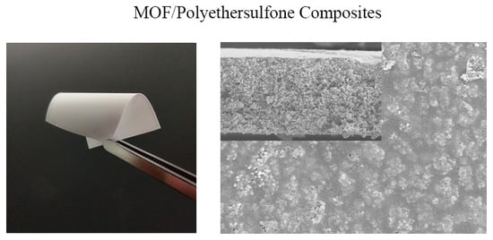
Composite materials that contain metal-organic frameworks (MOFs) as a filler and a polymer matrix have attracted attention because they present a combination of high porosity and structural integrity. Phase compatibilities of the MOF and polymer play a vital role in the formation of the composites. In particular, the stiff polymer cannot easily adapt to penetrate into the surface pore of MOF and mainly depends on chemical attractions to form the MOF/polymer composites. We report the synthesis of MOF/polyethersulfone (Young’s modulus = ~2.6 GPa) via different fabrication methods, different MOF types and particle sizes, and different solvents. The formed network structures are robust, monolithic composites with 60% MOF loadings; also, the MOF surface area and porosity were fully preserved. The study explored the formation of the composite between MOF and a stiff polymer and encourages the design of more MOF/polymer composite materials across a wide range of applications.

Graphical Abstract

1. Introduction

Because of their high porosity and tunable porous architecture, metal-organic frameworks (MOFs) have attracted a lot of attention over the past few years in terms of energy storage, mixture separation, air purification, and many related applications [1]. However, until now, exciting news regarding the successful industrial applications of MOFs has been scarce. One main reason for this is the crystallinity of MOFs, which makes it difficult to form their bulk materials and then severely limits their manipulation and processability [2]. To solve this problem, the chemical combination of MOFs with a continuous polymer is believed to be an efficient way to accelerate the real applications of MOFs.
A large number of MOF matrix composites have been prepared using polymer materials as a continuous phase or support. The main preparation methods include phase inversion, casting and solvent evaporation, interface polymerization, in situ growth, and layer-by-layer self-assembly [3,4,5,6,7,8,9]. ZIF-8, UiO-66, Cr-MIL-101, and other MOFs have been successfully combined with polyvinylidene fluoride (PVDF), polyethylenimine (PEI), polystyrene (PS), and polymers of intrinsic microporosity (PIMs) [10,11,12,13]. Among them, polyethersulfone (PES), is broadly used in the field of filtration because of its outstanding properties such as oxidative, thermal, and hydrolytic stability, mechanical strength, and chemical inertness across the entire PH range [14,15]. It is highly expected that MOFs can be endowed with the excellent properties of PES via the formation of composite materials. The quality of the composites formed mainly depends on the compatibility of the MOF and polymer used. It is believed that the mechanical properties of polymers play an important role in the formation of the MOF/polymer interface [16]. Soft polymers (Young’s modulus < 1 GPa) adapt easily to the morphology of the MOF surface and thus, show good two-phase compatibility. The elastic modulus of PES is ~2.6 GPa, which is much stronger than the Young’s modulus of soft polymers, and thus it is difficult for PES to adapt to the pore structure of MOFs. For the synthesis of MOF/PES composites, it is preferential to use PES as the support for the seed growth of the MOF layer [17] to grow MOF in situ in PES [18]. Although solidification of an MOF-PES mixed solution, which is a more efficient and direct strategy, has been used to synthesize MOF/PES composite beads [19,20] and a membrane [21,22,23], controllable synthesis of MOF/PES composites is highly necessary.
Herein, three kinds of MOFs that have a stable structure and performance (ZIF-8, HKUST-1 and UiO-66) were selected as filling materials, and PES was used as a matrix to prepare MOF/PES composite materials. The effects of fabrication, MOF loading, and solvent on the structure and morphology of the MOF/PES composites were studied.

2. Materials and Methods

2.1. Materials

The raw materials were zinc nitrate hexahydrate (99.99%), copper nitrate trihydrate (99%), zirconium(IV) chloride (98%), 2-methylimidazole (2-MeIm, 98%), 1,3,5-benzenetricarboxylic acid (H3BTC, 98%), terephthalic acid (PTA,99%), and glacial acetic acid (99.5%) and were purchased from Aladdin (Shanghai, China). Polyethersulfone (PES) polymer was supplied by BASF Company (Ludwigshafen, Germany). All of the solvents, including N,N-dimethylformamide (DMF), N-methyl-2-pyrrolidone (NMP), N-N-dimethyl-acetamide (DMA), and other organic solvents, were also purchased from Aladdin (Shanghai, China). All of the chemicals were used without any further treatment.

2.2. Synthesis of MOF and MOF/Polymer Composites

ZIF-8 synthesis [24]. A rapid synthesis method was used to synthesize nanosized ZIF-8 particles in a purely aqueous solution. Zn(NO3)2∙6H2O (1.17 g, 3.93 mmol) and 2-MeIm (23.05 g, 275.10 mmol) were each dissolved in deionized water (8 mL and 80 mL respectively) and then mixed together at room temperature. The molar ratio of Zn2+: 2-MeIm was 1:70, and the reaction time while stirring in the solution was about 5 min. Microsized ZIF-8 crystals were prepared via using a Zn2+: 2-MeIm molar ratio of 1:3 with 3 days of reaction time at 373 K.
HKUST-1 synthesis [25]. First, Cu(NO3)2∙3H2O (2.20 g, 9 mmol) and 1,3,5-benzenetricarboxylic acid (1.29 g, 6 mmol) were dissolved in separated methanol (80 mL for each vial), and the two solutions were combined to form a mixture. The mixture was stirred for 2 h at 800 rpm and left undisturbed at room temperature for 5 h. The particles were collected via centrifugation and washed with methanol at least 3 times, and the final product was vacuum-dried at 353 K overnight.
UIO-66 synthesis [26]. ZrCl4 (0.2378 g, 1 mmol) and terephthalic acid (0.1678 g, 1 mmol) were dissolved in 20mL of DMF with the addition of 0.115 mL of glacial acetic acid (2 mmol). After stirring for about 30 min, the solution was heated to 393 K for 24 h of reaction. The collected particles were washed at least 3 times with DMF and methanol. The particles were then vacuum-dried at 353 K overnight to obtain the final product.
MOF/PES composite synthesis. MOF powder (0.21–1.17 g corresponding to 30–70 wt.% loading of MOF in composites) was suspended in 5 mL of solvent (DMF, NMP or DMA) for 24 h via mechanical stirring at room temperature. PES particles (0.5 g) were then gradually added to the MOF solution under stirring. The MOF-polymer solution was stirred for another 24 h at 333 K, and the prepared mixed solution was then poured into a Petri dish for casting. After that, two separate methods were used to obtain the final composite. One method is phase inversion based on solvent exchange. In this method, a nonsolvent liquid (deionized water:ethanol = 50 mL:50 mL) was used for exchange and was poured into a Petri dish at room temperature for precipitation. The products were then repeatedly washed with refreshed non-solvent to remove the remaining solvent. Finally, the composites were dried in air at room temperature. The other method is the solvent evaporation technique. In this method, a Petri dish is placed in an oven at 363 K and left uncovered over night to allow the evaporation of the solvent. The layers were then peeled off of the Petri dishes, and finally, the products were treated overnight in an oven at 353 K and then in a vacuum oven at 393 K for another 12 h to completely remove the remaining solvent. The whole synthesis process is shown in Scheme 1.

2.3. Measurements

An X-ray diffractometer (40 kV, 30 mA, Cu Kα, λ = 0.15406 nm) was used to obtain powder X-ray diffraction (PXRD) patterns of the MOFs and their composites. The scanning rate was 5° min−1 over a PXRD range from 5° to 40°. Scanning electron microscopy (SEM) was conducted using an S-4800 microscope (5.0 kV accelerating voltage, Hitachi, Tokyo, Japan) to characterize the morphologies of the synthesized MOF/PES composite materials. An automatic volumetric adsorption apparatus (Micrometrics ASAP 2020, Shanghai, China) was used to measure the nitrogen sorption isotherms at 77 K. The as-synthesized samples (weight 100–200 mg) were activated in a quartz tube at 378 K for 12 h. DMF and other volatile compounds were completely removed before measurements were made.

3. Results

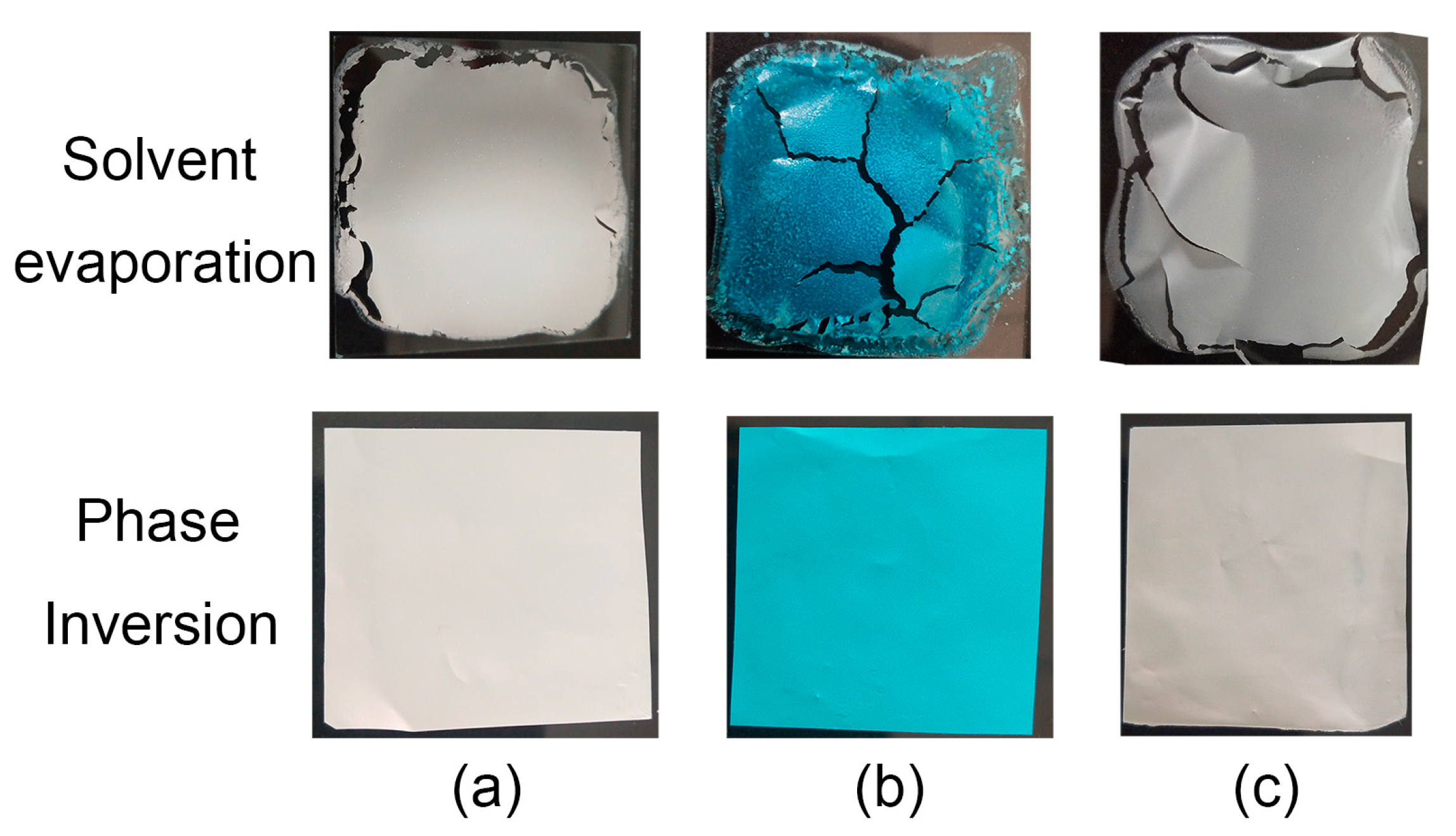
Figure 1 shows optical images of the MOF/PES composite materials that were prepared via solvent evaporation and the phase inversion method. The blank experiment with presence of only PES in solvent by the two methods can be found in Figure S1. It is clear that the composites cracked after solvent evaporation (upper panels in Figure 1). This is probably because of the internal stress concentration. In contrast, the composite materials fabricated via the phase inversion method has better integrity (lower panels in Figure 1). These layers can even bear folding deformation, which indicates that they have good flexibility (Figure S2).
PXRD was used to investigate the high quality of the MOF/PES composites that were prepared via the phase inversion method (Figure 2). For comparison, the PXRD patterns of pure MOF and pure PES are also presented in Figure 2. The diffraction patterns of the MOF/PES composites are similar to that of the pure MOF counterpart, and this indicates that the crystal structure of MOFs was preserved upon the incorporation of polymer when our fabrication approach was used. One exception is HKUST-1/PES, which shows a degradation of one peak that is around 5.8° (Figure 2b). The small peak corresponds to the (111) reflection and its degradation has been also observed in HKUST-1/acrylamide composites [12] and HKUST-1/cellulose acetate mixed matrix membranes [6]. The presence of solvent molecules in the pores of the synthesized pure HKUST-1 could associate with the small diffraction reflection at 5.8° in Figure 2b. Still, other peaks in the PXRD pattern of HKUST-1/PES are consistent with those in the PXRD pattern of pure HKUST-1. This may be ascribed to slight distortion of the HKUST-1 crystal structure, instead of the crystal structure being lost completely.
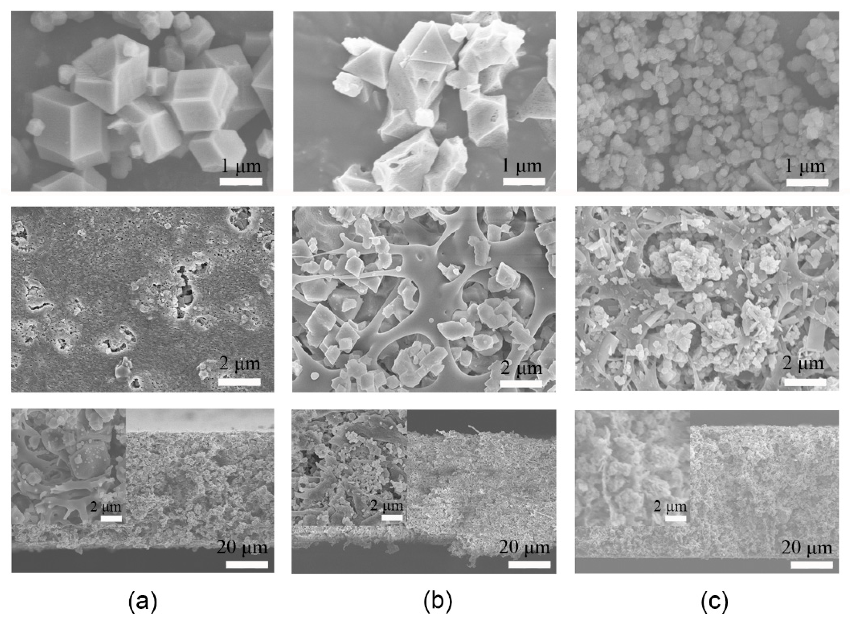
Because of intrinsic differences between ordered and disordered phases, the morphology of the MOF and polymer chains in composites is interesting. Figure 3 shows SEM images of the pure MOFs (microsized crystals) and the composites that were incorporated into different types of MOFs. Strictly, UiO-66 shows smaller crystal size (10−1 micrometer level), which is still larger than the nanosized ZIF-8 crystals (Figure 4a). For comparison, the same MOF loading (60 wt.%) in different composites was used. ZIF-8/PES shows a continuous and tightly-packed morphology from the top surface of the composites (Figure 3a middle panel). In contrast, HKUST-1 and UiO-66 crystalline particles agglomerated and were surrounded by PES ribbons (Figure 3b,c middle panels). The ribbon-like PES indicates that the continuous polymer phase was interrupted by HKUST-1 and UiO-66 crystals, and then phase separation appeared. Furthermore, cross-sectional images of the composites show the presence of the ribbon-like PES inside all three types of MOF/PES (Figure 3 lower panels). It should be noted that the size of the ZIF-8 crystal is larger than that of the HKUST-1 and UiO-66 crystals (Figure 3 enlarged inset images). To clarify the size effect, nanosized ZIF-8 crystals (Figure 4a) were chosen for the synthesis of the ZIF-8/PES composite. Both the top surface (Figure 4b) and the cross-section (Figure 4c) of the nanosized ZIF-8/PES composite show the absence of the ribbon-like PES, and a sponge-like structure appeared inside the composite. Furthermore, the composite with embedded nanosized ZIF-8 crystals (Figure 4b) has a dense and less broken surface. This kind of morphology implies that there is better phase compatibility in the nanosized ZIF-8/PES composite than that in microsized ZIF-8/PES, HKUST-1/PES or UiO-66/PES.
Interfacial interactions can be used to understand the two-phase affinity in MOF/PES composites. The main free group on the surface of ZIF-8 [27], HKUST-1 [28], and UiO-66 [16] is NH, CH3, and OH groups, respectively. The most significant interactions should involve hydrogen bonds between the free groups of MOF and the oxygen of PES, that is, the N-H∙∙∙∙O bond (ZIF-8/PES), C-H∙∙∙∙O bond (HKUST-1/PES), and O-H∙∙∙∙O bond (UiO-66/PES). According to the electronegativity of the elements, the decreasing strength of single hydrogen bond is in the order of O-H∙∙∙∙O, N-H∙∙∙∙O, and C-H∙∙∙∙O. The values of the density of free groups on the MOF surfaces are 0.04 Å−3, 0.02 Å−3, and 0.03 Å−3 for ZIF-8, HKUST-1, and UiO-66, respectively. Thus, ZIF-8 actually has the most free groups on surface, and in ZIF-8, the hydrogen bond interactions with PES are medium strength. UiO-66 has the strongest hydrogen bond with PES (O-H∙∙∙∙O), but the density of the surface OH group is medium. The morphologies shown in Figure 3 and Figure 4 indicate that the ZIF-8/PES composite is higher quality than the UiO-66/PES composite. This indicates that the density of the interfacial active sites may determine the compatibility of the MOF/polymer when the strength difference of single hydrogen bond interactions is small (O-H∙∙∙∙O vs. N-H∙∙∙∙O).
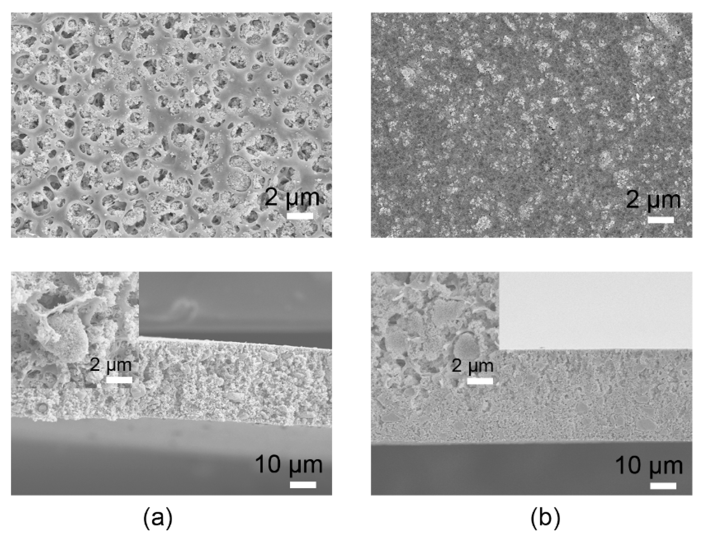
Focusing on nanosized ZIF-8/PES, the effects of the solvent on the morphologies of the composites were investigated (Figure 4 and Figure 5). Here, three types of polar and water-miscible solvents (DMF, DMA, and NMP) were chosen to synthesize the hydrophobic asymmetric ZIF-8/PES via the phase inversion method. Figure 5a shows the mesoporous surface of the ZIF-8/PES composite that was prepared using DMA. In contrast, a dense surface of the ZIF-8/PES composites was obtained when DMF and NMP were used as the solvents.
Solvent volatility can be used to understand the above solvent effect. It has been reported that solvents with higher volatility can result in larger pore sizes in polymer matrix membranes because of rapid evaporation from the polymer [29]. The boiling point values of DMA, DMF, and NMP are 439 K, 426 K, and 475 K, respectively [30]. Hydrogen bonding values (δH) suppress solvent volatility. The δH value of DMF is 5.5, which is higher than that of DMA (5.0) and that of NMP (3.5). Thus, DMA is more volatile and evaporates quickly from the ZIF-8/PES composite; this leaves a porous surface, as shown in the upper panel of Figure 5a. Furthermore, a very small difference between the solubility parameters of the solvent and the polymer was necessary to obtain a workable zeolite-filled mixed-matrix membrane [30]. The Hansen solubility parameters for both the DMF and NMP solvents are closer to that of PES than that of DMA [31]. On the basis of Hansen-solubility parameters, the strong polymer–solvent interactions indicate the low inter-diffusion rate for DMF and NMP during the phase inversion process. Slow diffusion can delay exchange between the solvent and nonsolvent, thereby stimulating delayed demixing. Precipitation that starts after that delayed time leads to a dense surface of the ZIF-8/PES composite, as seen in Figure 4b and Figure 5b.
Different ZIF-8 loading was employed to synthesize the nanosized ZIF-8/PES composites (Figure 6). Under low loading, a smooth surface and isolated ZIF-8 crystals coexist (Figure 6a). With an increase in the ZIF-8 loading (from 40 wt.% to 60 wt.%), ZIF-8 crystals gradually were wrapped by PES (Figure 6). A further increase in the ZIF-8 loading will lead to the discontinuous PES matrix (Figure S3) and even to MOF-polymer phase separation.
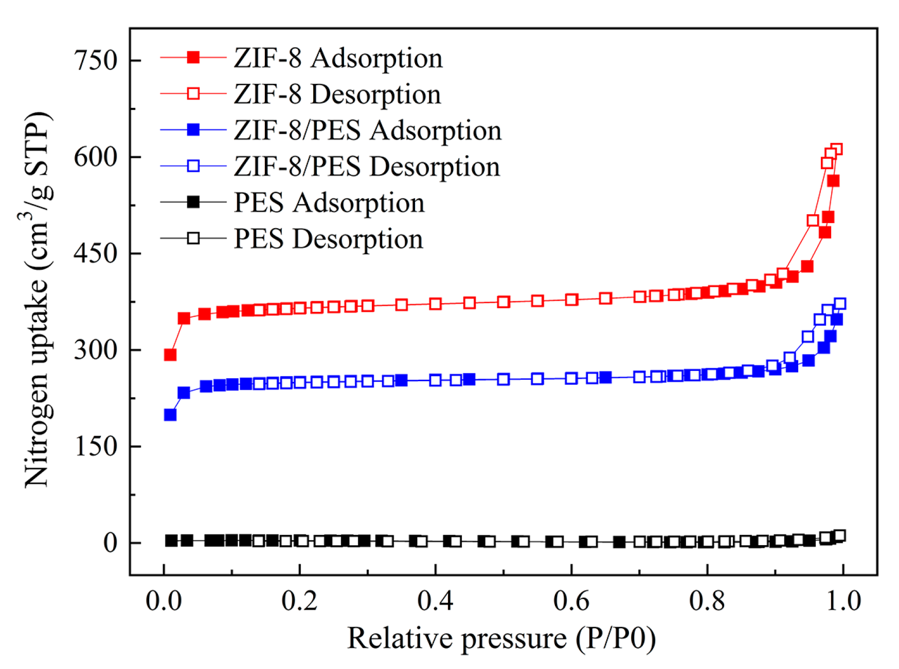
Nitrogen sorption experiments at 77 K were performed to check the porosity of the nanosized ZIF-8(60 wt.%)/PES composite materials. Type-IV isotherms that were observed for both pure ZIF-8 and the ZIF-8/PES composite show significant hysteresis in the adsorption-desorption process (Figure 7). At a relative pressure of 0.1, the uptake of nitrogen by ZIF-8 in the composites is about 246 cm3∙g−1, and this is close to that of pure ZIF-8 (360 cm3∙g−1) but much larger than that of pure PES (3.8 cm3∙g−1). The Brunauer-Emmett-Teller (BET) surface area (SBET) and the microporous volume (Vmicro) in ZIF-8/PES composites are 773 m2∙g−1 and 0.34 cm3∙g−1 respectively. Pure PES has a low BET surface (12 m2∙g−1) and microporous volume (0.008 cm3∙g−1). With 60 wt% loading of ZIF-8 in the composite, the porosity of composites was almost completely inherited from pure ZIF-8 (SBET = 1222 m2∙g−1 and Vmicro = 0.52 cm3∙g−1). The above observations indicate that the adsorption properties of the ZIF-8/PES composite are close to those ZIF-8.

4. Conclusions

In this study, we proposed a controllable synthesis of MOF/PES composite materials. Three types of MOFs (ZIF-8, HKUST-1, and UiO-66) were combined with a stiff polymer (PES) via the solvent exchange method instead of via solvent evaporation. Microscopic images show that the composite that had nanosized ZIF-8 particles has both an integrated surface and a mixed-phase morphology, indicating good phase compatibility. A ZIF-8 loading of 60% can be achieved in the nanosized ZIF-8/PES composite, and this can fully preserve the ZIF-8 surface area and porosity. This work on the controllable fabrication of stiff polymer–MOF composite materials reveals the experimental factors that influence the quality of the composites, and this can contribute to the development of more MOF/polymer composites for real applications.

Supplementary Materials

The following are available online at https://www.mdpi.com/2073-4352/10/1/39/s1, Figure S1: The blank experiment with presence of only polymer in solvent employing the solvent evaporation and the solvent exchange method, Figure S2: Optical images of ZIF-8/PES, HKUST-1/PES, and UiO-66/PES membranes, Figure S3: Optical images of the composites with the ZIF-8 loading of 60 wt.% and 65 wt.%.

Author Contributions

Conceptualization, B.Z.; Investigation, X.G., B.Z. and J.W. All authors have read and agreed to the published version of the manuscript.

Funding

This research was funded by the National Natural Science Foundation of China (NSFC) (Grants No. 21503165), Scientific Research Program Funded by Shaanxi Provincial Education Department (Program No.17JK0491), Natural Science Basic Research Plan in Shaanxi Province of China (Program No. 2018JQ5085), and Shaanxi Province 100 plan.

Conflicts of Interest

The authors declare no conflict of interest.

References

  1. Furukawa, H.; Cordova, K.E.; O’Keeffe, M.; Yaghi, O.M. The chemistry and applications of metal-organic frameworks. Science 2013, 341, 1230444. [Google Scholar] [CrossRef] [Green Version]
  2. Kitao, T.; Zhang, Y.; Kitagawa, S.; Wang, B.; Uemura, T. Hybridization of MOFs and polymers. Chem. Soc. Rev. 2017, 46, 3108–3133. [Google Scholar] [CrossRef]
  3. Ren, H.; Jin, J.; Hu, J.; Liu, H. Affinity between metal–organic frameworks and polyimides in asymmetric mixed matrix membranes for gas separations. Ind. Eng. Chem. Res. 2012, 51, 10156–10164. [Google Scholar] [CrossRef]
  4. Li, L.; Yao, J.; Xiao, P.; Shang, J.; Feng, Y.; Webley, P.A.; Wang, H.J.C.; Science, P. One-step fabrication of ZIF-8/polymer composite spheres by a phase inversion method for gas adsorption. Colloid. Polym. Sci. 2013, 291, 2711–2717. [Google Scholar] [CrossRef]
  5. Ma, J.; Guo, X.; Ying, Y.; Liu, D.; Zhong, C. Composite ultrafiltration membrane tailored by MOF@GO with highly improved water purification performance. Chem. Eng. J. 2017, 313, 890–898. [Google Scholar] [CrossRef] [Green Version]
  6. Hou, J.; Luan, Y.; Huang, X.; Gao, H.; Yang, M.; Lu, Y. Facile synthesis of Cu3(BTC)2/cellulose acetate mixed matrix membranes and their catalytic applications in continuous flow process. New J. Chem. 2017, 41, 9123–9129. [Google Scholar] [CrossRef]
  7. Xu, Y.M.; Chung, T.-S. High-performance UiO-66/polyimide mixed matrix membranes for ethanol, isopropanol and n-butanol dehydration via pervaporation. J. Membr. Sci. 2017, 531, 16–26. [Google Scholar] [CrossRef]
  8. Marti, A.M.; Venna, S.R.; Roth, E.A.; Culp, J.T.; Hopkinson, D.P. Simple fabrication method for mixed matrix membranes with in situ mof growth for gas separation. ACS Appl. Mater. Interfaces 2018, 10, 24784–24790. [Google Scholar] [CrossRef]
  9. Xiang, F.; Marti, A.M.; Hopkinson, D.P. Layer-by-layer assembled polymer/mof membrane for H2/CO2 separation. J. Membr. Sci. 2018, 556, 146–153. [Google Scholar] [CrossRef]
  10. Denny, M.S., Jr.; Cohen, S.M. In situ modification of metal–organic frameworks in mixed-matrix membranes. Angew. Chem. Int. Ed. 2015, 54, 9029–9032. [Google Scholar] [CrossRef]
  11. Gao, Y.; Qiao, Z.; Zhao, S.; Wang, Z.; Wang, J. In situ synthesis of polymer grafted ZIFs and application in mixed matrix membrane for CO2 separation. J. Mater. Chem. A 2018, 6, 3151–3161. [Google Scholar] [CrossRef]
  12. Jin, P.; Tan, W.; Huo, J.; Liu, T.; Liang, Y.; Wang, S.; Bradshaw, D. Hierarchically porous MOF/polymer composites via interfacial nanoassembly and emulsion polymerization. J. Mater. Chem. A 2018, 6, 20473–20479. [Google Scholar] [CrossRef] [Green Version]
  13. Benzaqui, M.; Semino, R.; Menguy, N.; Carn, F.; Kundu, T.; Guigner, J.-M.; McKeown, N.B.; Msayib, K.J.; Carta, M.; Malpass-Evans, R.; et al. Toward an understanding of the microstructure and interfacial properties of PIMs/ZIF-8 mixed matrix membranes. ACS Appl. Mater. Interfaces 2016, 8, 27311–27321. [Google Scholar] [CrossRef] [PubMed]
  14. Zhao, C.; Xue, J.; Ran, F.; Sun, S. Modification of polyethersulfone membranes – a review of methods. Prog. Mater Sci. 2013, 58, 76–150. [Google Scholar] [CrossRef]
  15. Mohammadnezhad, F.; Feyzi, M.; Zinadini, S. A novel Ce-MOF/PES mixed matrix membrane; synthesis, characterization and antifouling evaluation. J. Ind. Eng. Chem. 2019, 71, 99–111. [Google Scholar] [CrossRef]
  16. Semino, R.; Moreton, J.C.; Ramsahye, N.A.; Cohen, S.M.; Maurin, G. Understanding the origins of metal–organic framework/polymer compatibility. Chem. Sci. 2018, 9, 315–324. [Google Scholar] [CrossRef] [PubMed] [Green Version]
  17. Ge, L.; Zhou, W.; Du, A.; Zhu, Z. Porous polyethersulfone-supported zeolitic imidazolate framework membranes for hydrogen separation. J. Phys. Chem. C 2012, 116, 13264–13270. [Google Scholar] [CrossRef]
  18. Kang, Z.; Peng, Y.; Qian, Y.; Yuan, D.; Addicoat, M.A.; Heine, T.; Hu, Z.; Tee, L.; Guo, Z.; Zhao, D. Mixed matrix membranes (mmms) comprising exfoliated 2D covalent organic frameworks (COFs) for efficient CO2 separation. Chem. Mater. 2016, 28, 1277–1285. [Google Scholar] [CrossRef]
  19. Valizadeh, B.; Nguyen, T.N.; Smit, B.; Stylianou, K.C. Porous metal–organic framework@polymer beads for iodine capture and recovery using a gas-sparged column. Adv. Funct. Mater. 2018, 28, 1801596. [Google Scholar] [CrossRef]
  20. Abbasi, Z.; Shamsaei, E.; Fang, X.-Y.; Ladewig, B.; Wang, H. Simple fabrication of zeolitic imidazolate framework ZIF-8/polymer composite beads by phase inversion method for efficient oil sorption. J. Colloid Interface Sci. 2017, 493, 150–161. [Google Scholar] [CrossRef]
  21. Yeo, Z.Y.; Tan, P.Y.; Chai, S.-P.; Zhu, P.W.; Mohamed, A.R. Continuous polycrystalline ZIF-8 membrane supported on CO2-selective mixed matrix supports for CO2/CH4 separation. RSC Adv. 2014, 4, 52461–52466. [Google Scholar] [CrossRef]
  22. Li, Y.; Wee, L.H.; Volodin, A.; Martens, J.A.; Vankelecom, I.F.J. Polymer supported ZIF-8 membranes prepared via an interfacial synthesis method. Chem. Commun. 2015, 51, 918–920. [Google Scholar] [CrossRef] [PubMed] [Green Version]
  23. Gholami, F.; Zinadini, S.; Zinatizadeh, A.A.; Abbasi, A.R. TMU-5 metal-organic frameworks (MOFs) as a novel nanofiller for flux increment and fouling mitigation in PES ultrafiltration membrane. Sep. Purif. Technol. 2018, 194, 272–280. [Google Scholar] [CrossRef]
  24. Pan, Y.; Liu, Y.; Zeng, G.; Zhao, L.; Lai, Z. Rapid synthesis of zeolitic imidazolate framework-8 (ZIF-8) nanocrystals in an aqueous system. Chem. Commun. 2011, 47, 2071–2073. [Google Scholar] [CrossRef]
  25. Wang, F.; Guo, H.; Chai, Y.; Li, Y.; Liu, C. The controlled regulation of morphology and size of HKUST-1 by “coordination modulation method”. Microporous Mesoporous Mater. 2013, 173, 181–188. [Google Scholar] [CrossRef]
  26. Lu, G.; Cui, C.; Zhang, W.; Liu, Y.; Huo, F. Synthesis and self-assembly of monodispersed metal-organic framework microcrystals. Chem.-Asian J. 2013, 8, 69–72. [Google Scholar] [CrossRef]
  27. Zhu, Y.; Ciston, J.; Zheng, B.; Miao, X.; Czarnik, C.; Pan, Y.; Sougrat, R.; Lai, Z.; Hsiung, C.-E.; Yao, K.; et al. Unravelling surface and interfacial structures of a metal–organic framework by transmission electron microscopy. Nat. Mater. 2017, 16, 532–536. [Google Scholar] [CrossRef] [Green Version]
  28. Amirjalayer, S.; Tafipolsky, M.; Schmid, R. Surface termination of the metal-organic framework HKUST-1: A theoretical investigation. J. Phys. Chem. Lett. 2014, 5, 3206–3210. [Google Scholar] [CrossRef]
  29. Adams, F.V.; Nxumalo, E.N.; Krause, R.W.M.; Hoek, E.M.V.; Mamba, B.B. The influence of solvent properties on the performance of polysulfone/β-cyclodextrin polyurethane mixed-matrix membranes. J. Appl. Polym. Sci. 2013, 130, 2005–2014. [Google Scholar] [CrossRef]
  30. Şener, T.; Okumuş, E.; Gürkan, T.; Yilmaz, L. The effect of different solvents on the performance of zeolite-filled composite pervaporation membranes. Desalination 2010, 261, 181–185. [Google Scholar] [CrossRef]
  31. Guan, R.; Dai, H.; Li, C.; Liu, J.; Xu, J. Effect of casting solvent on the morphology and performance of sulfonated polyethersulfone membranes. J. Membr. Sci. 2006, 277, 148–156. [Google Scholar] [CrossRef]
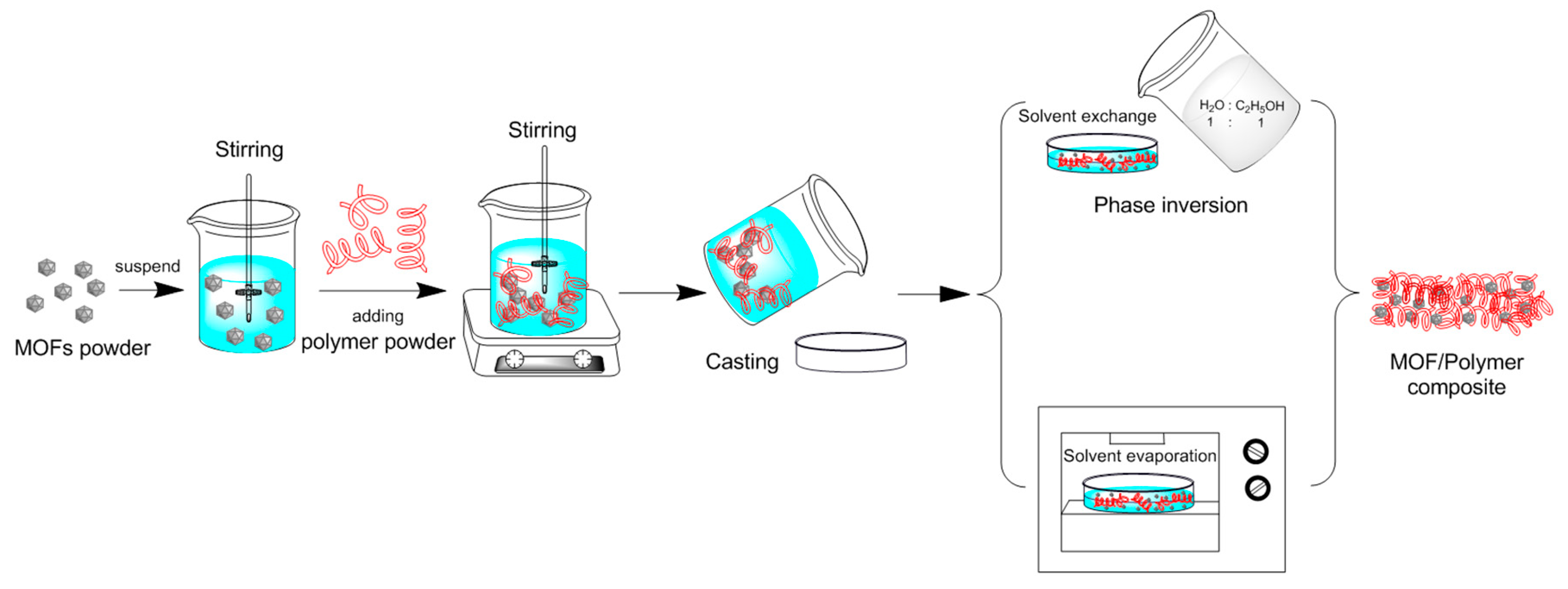
Scheme 1. Schematic drawing of the synthesis approach used to prepare MOF/polymer composite materials.
Crystals 10 00039 sch001
Figure 1. Optical images of (a) ZIF-8/PES, (b) HKUST-1/PES, and (c) UiO-66/PES composite materials prepared via solvent evaporation (top panels) and the solvent exchange method (lower panels). The solvent was DMF.
Crystals 10 00039 g001
Figure 2. PXRD patterns of MOF, PES and MOF/PES composite materials employing (a) ZIF-8, (b) HKUST-1, and (c) UiO-66.
Crystals 10 00039 g002
Figure 3. SEM images of (a) microsized ZIF-8 and ZIF-8/PES, (b) microsized HKUST-1 and HKUST-1/PES, and (c) microsized UiO-66 and UiO-66/PES. Top panels are the pure MOFs. Middle and bottom panels respectively correspond to the surface and cross-section of the membrane. Inset pictures show enlarged images. The solvent was DMF, and the loading of MOF was 60 wt.%.
Crystals 10 00039 g003
Figure 4. SEM images of (a) nanosized pure ZIF-8, (b) surface of ZIF-8/PES, and (c) cross-section of ZIF-8/PES. The inset picture shows an enlarged image. The solvent was DMF, and the loading of ZIF-8 was 60 wt.%.
Crystals 10 00039 g004
Figure 5. Nanosized ZIF-8/PES composite materials prepared using (a) DMA and (b) NMP as the solvents. Top panels are images of the surface, and lower panels are cross-sectional images. Loading of ZIF-8 was 60 wt.%.
Crystals 10 00039 g005
Figure 6. Composite materials with different ZIF-8 loading (nanosized crystals). DMF was used as the solvent.
Crystals 10 00039 g006
Figure 7. Nitrogen adsorption−desorption isotherms at 77 K for nanosized ZIF-8, PES, and nanosized ZIF-8/PES composites. For composites, the solvent was DMF, and the ZIF-8 loading was 60 wt.%.
Crystals 10 00039 g007