Comparative Studies of Fischer-Tropsch Synthesis on Iron Catalysts Supported on Al2O3-Cr2O3 (2:1), Multi-Walled Carbon Nanotubes or BEA Zeolite Systems

 , ,
, ,  , ,
, , 
Abstract
:
1. Introduction
2. Results and Discussion
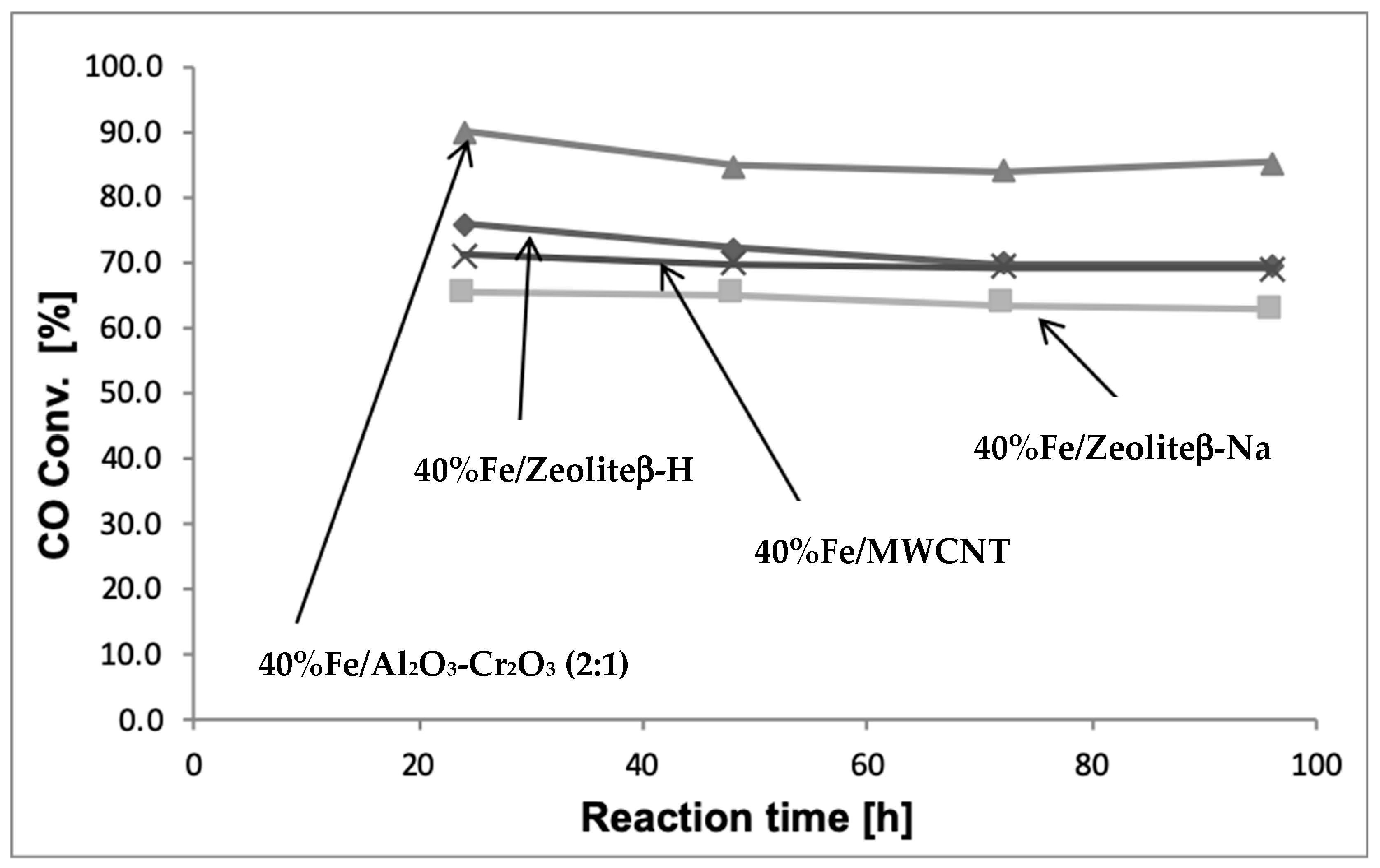
2.1. Influence of the Catalytic Material Composition on the Catalytic Reactivity of Monometallic Iron Catalysts in the Hydrogenation of CO
2.2. Specific Surface Area (SSA) and Pore Size of the Investigated Catalytic Systems
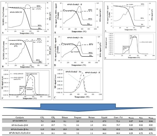
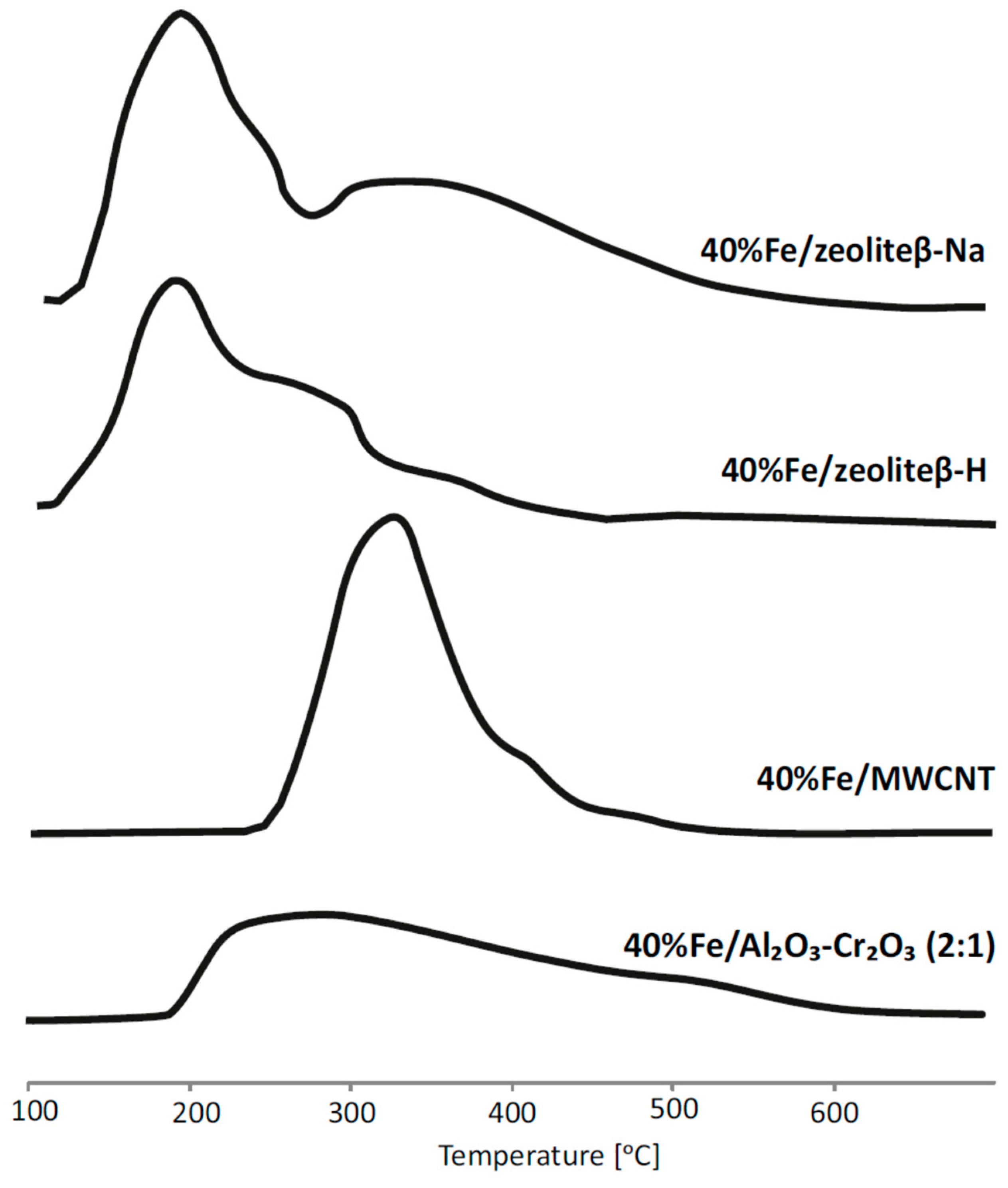
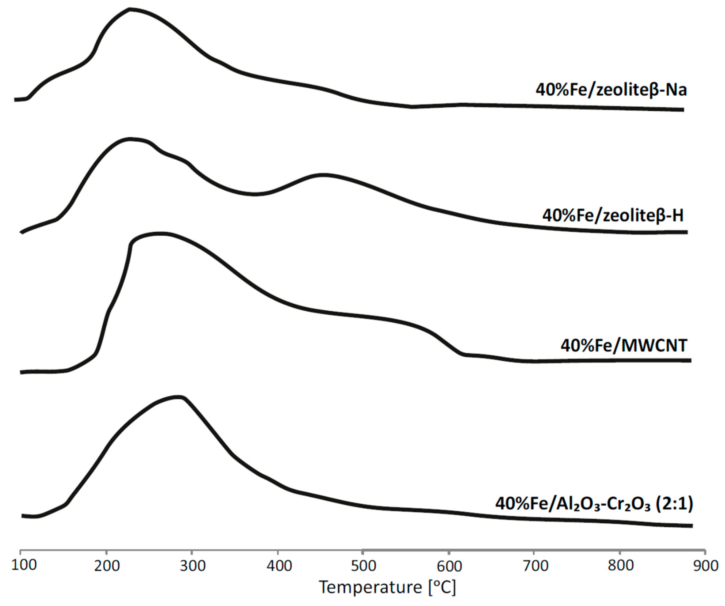
2.3. Reduction Behaviour of Catalytic Material
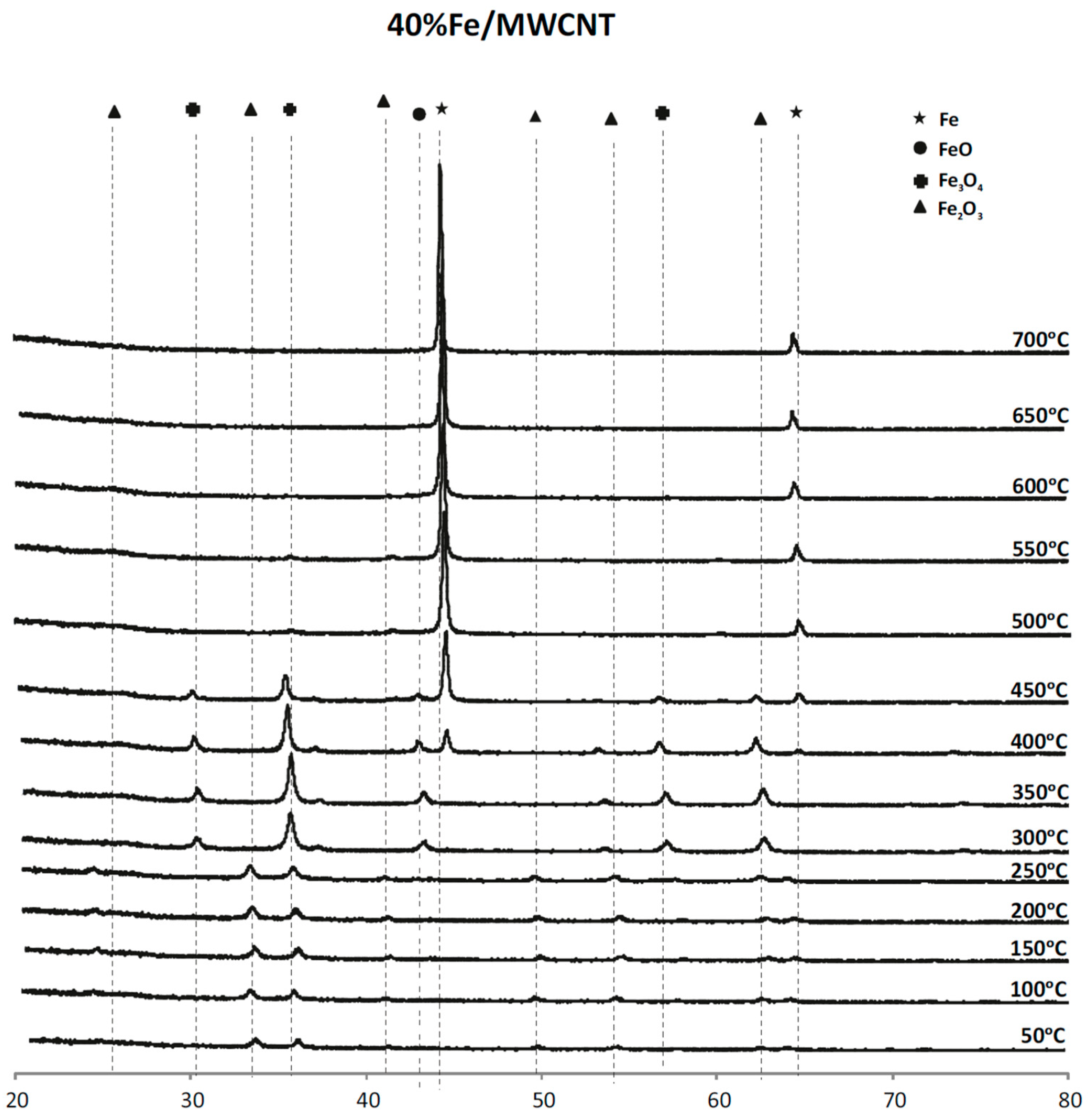
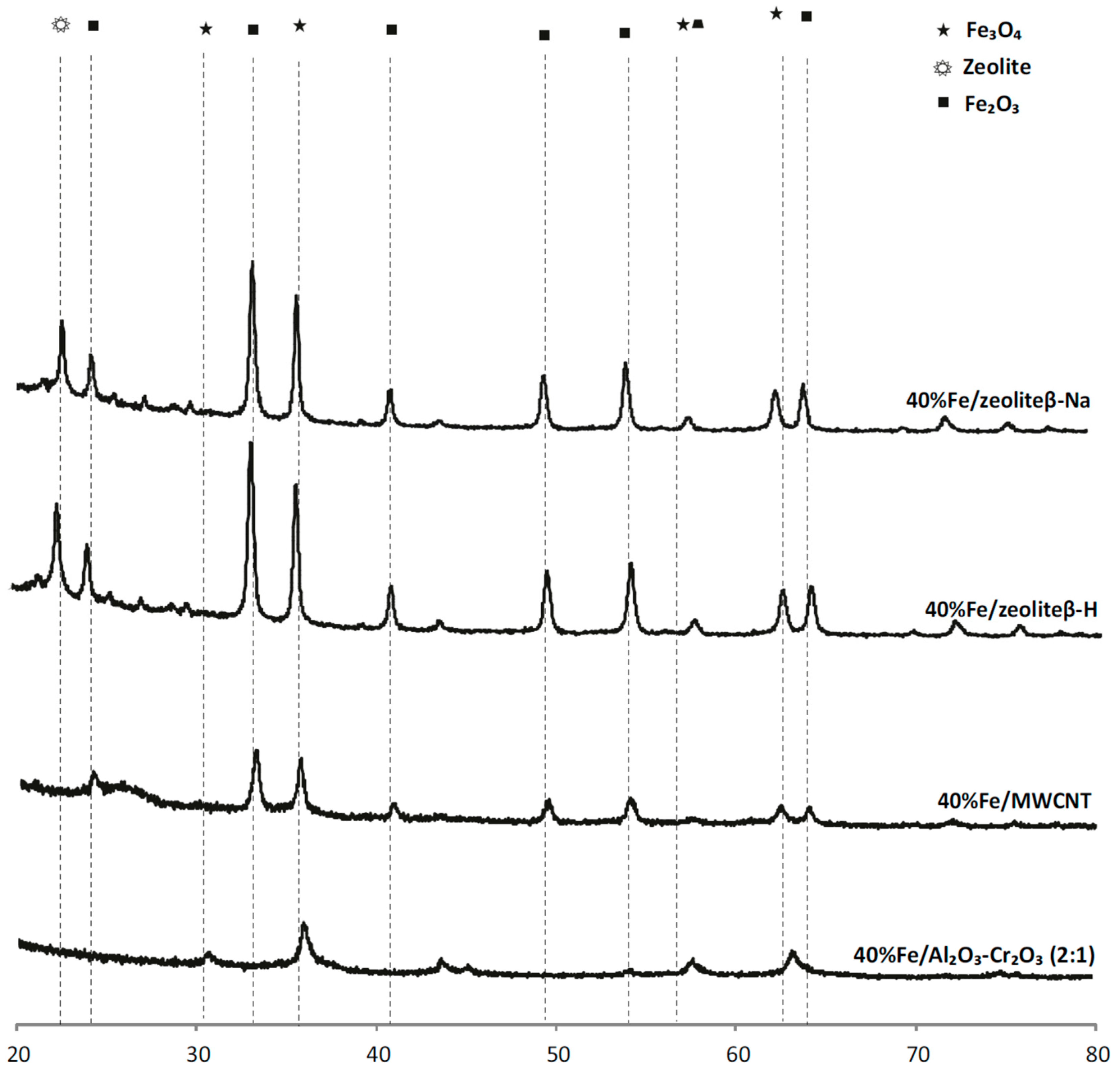
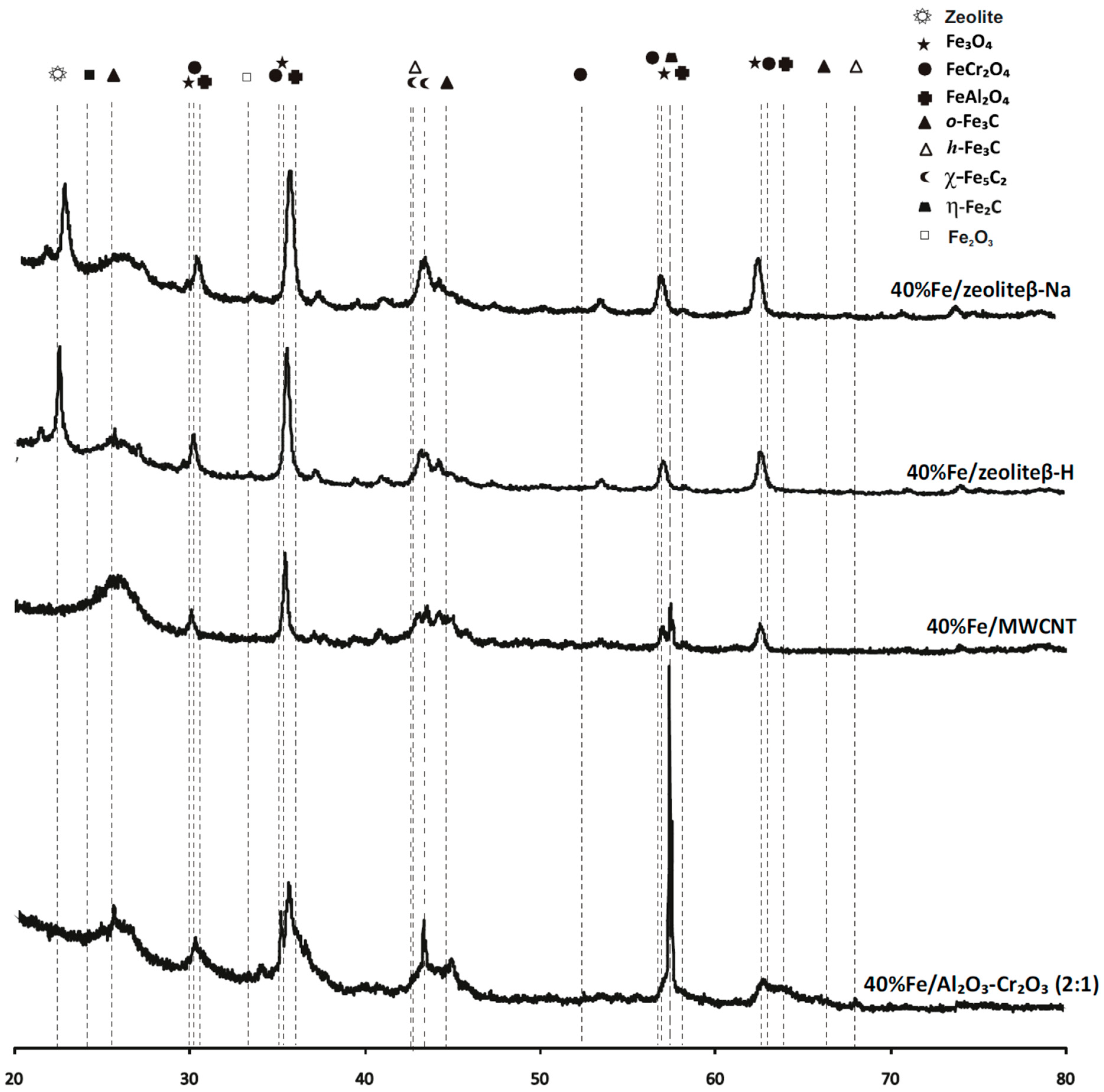
2.4. Phase Composition Research of Iron Supported Catalysts
2.5. The Influence of the Catalytic Support on the Acidity Properties of the Fe Based Catalysts
2.6. The Influence of the Carrier Type on the Catalyst Basicity
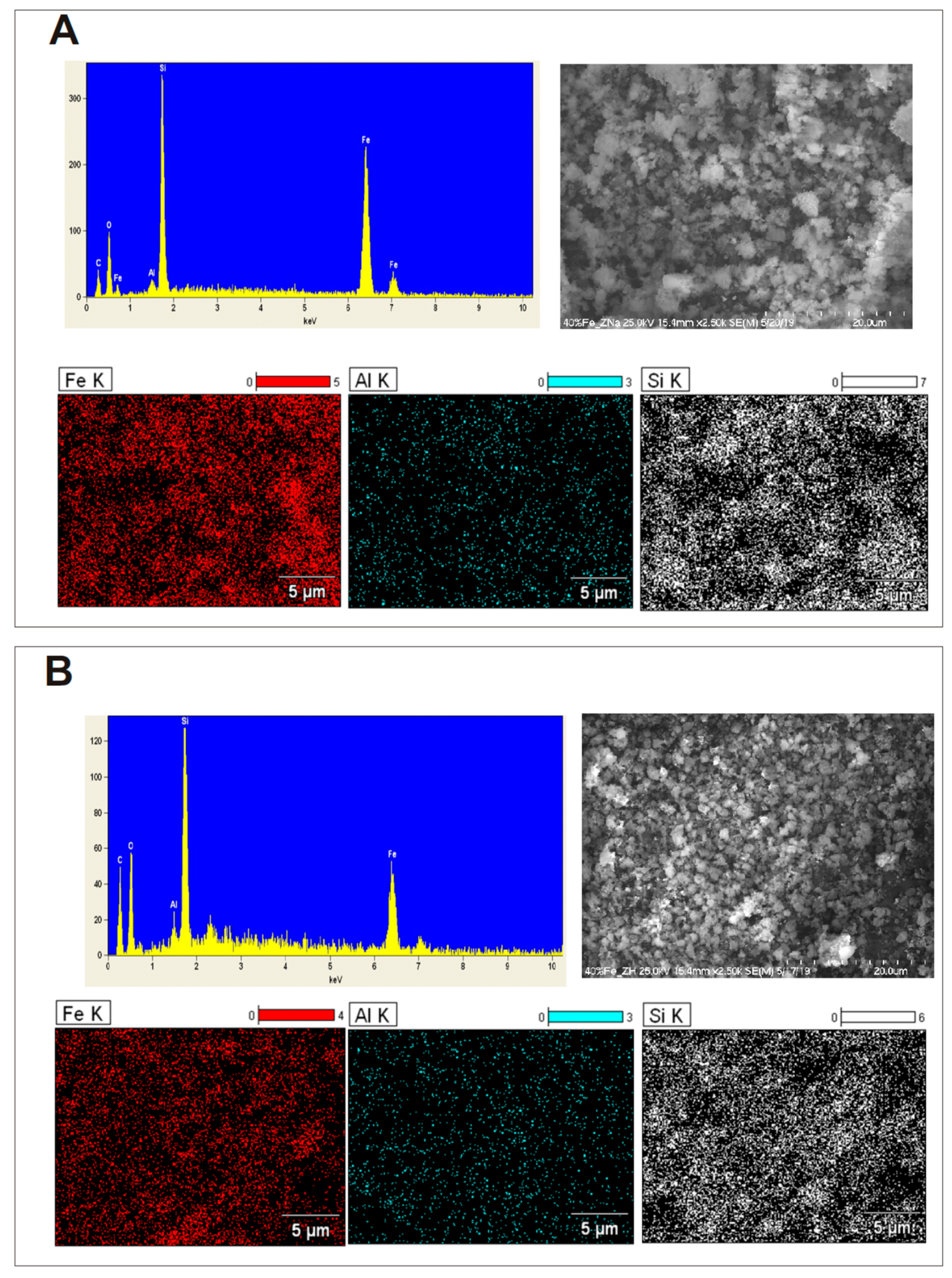
2.7. SEM-EDS Measurements of Iron Catalysts Supported on Two Types of Zeolites
3. Experimental
3.1. Supports and Catalysts Preparation
3.2. Characterization of the Catalytic Material
3.3. Catalytic Activity Measurements in the F-T Process
4. Conclusions
Supplementary Materials
Author Contributions
Funding
Conflicts of Interest
References
- Tijmensen, M.J.A.; Faaij, A.P.C.; Hamelinck, C.N.; van Hardeveld, M.R.M. Exploration of the possibilities for production of Fischer Tropsch liquids and power via biomass gasification. Biomass Bioenergy 2002, 23, 129–152. [Google Scholar] [CrossRef]
- Mierczynski, P.; Dawid, B.; Maniukiewicz, W.; Mosinska, M.; Zakrzewski, M.; Ciesielski, R.; Kedziora, A.; Dubkov, S.; Gromov, D.; Rogowski, J.; et al. Fischer–Tropsch synthesis over various Fe/Al2O3–Cr2O3 catalysts. React. Kinet. Mech. Catal. 2018, 124, 545–561. [Google Scholar] [CrossRef]
- Bukur, D.B.; Nowicki, L.; Manne, R.K.; Lang, X.S. Activation Studies with a Precipitated Iron Catalyst for Fischer-Tropsch Synthesis: II. Reaction Studies. J. Catal. 1995, 155, 366–375. [Google Scholar] [CrossRef]
- Chalupka, K.A.; Maniukiewicz, W.; Mierczynski, P.; Maniecki, T.; Rynkowski, J.; Dzwigaj, S. The catalytic activity of Fe-containing SiBEA zeolites in Fischer–Tropsch synthesis. Catal. Today 2015, 257, 117–121. [Google Scholar] [CrossRef]
- Peña, D.; Cognigni, A.; Neumayer, T.; van Beek, W.; Jones, D.S.; Quijada, M.; Rønning, M. Identification of carbon species on iron-based catalysts during Fischer-Tropsch synthesis. Appl. Catal. A Gen. 2018, 554, 10–23. [Google Scholar] [CrossRef]
- Zhang, J.; Chen, J.; Ren, J.; Li, Y.; Sun, Y. Support effect of Co/Al2O3 catalysts for Fischer–Tropsch synthesis. Fuel 2003, 82, 581–586. [Google Scholar] [CrossRef]
- Bezemer, G.L.; Bitter, J.H.; Kuipers, H.P.C.E.; Oosterbeek, H.; Holewijn, J.E.; Xu, X.; Kapteijn, F.; van Dillen, A.J.; de Jong, K.P. Cobalt Particle Size Effects in the Fischer−Tropsch Reaction Studied with Carbon Nanofiber Supported Catalysts. J. Am. Chem. Soc. 2006, 128, 3956–3964. [Google Scholar] [CrossRef]
- Guczi, L.; Stefler, G.; Geszti, O.; Koppány, Z.; Kónya, Z.; Molnár, É.; Urbán, M.; Kiricsi, I. CO hydrogenation over cobalt and iron catalysts supported over multiwall carbon nanotubes: Effect of preparation. J. Catal. 2006, 244, 24–32. [Google Scholar] [CrossRef]
- Bahome, M.C.; Jewell, L.L.; Hildebrandt, D.; Glasser, D.; Coville, N.J. Fischer–Tropsch synthesis over iron catalysts supported on carbon nanotubes. Appl. Catal. A Gen. 2005, 287, 60–67. [Google Scholar] [CrossRef]
- Serp, P.; Corrias, M.; Kalck, P. Carbon nanotubes and nanofibers in catalysis. Appl. Catal. A Gen. 2003, 253, 337–358. [Google Scholar] [CrossRef]
- Rodríguez-reinoso, F. The role of carbon materials in heterogeneous catalysis. Carbon 1998, 36, 159–175. [Google Scholar] [CrossRef]
- Zhang, Z.; Zhang, J.; Wang, X.; Si, R.; Xu, J.; Han, Y.F. Promotional effects of multiwalled carbon nanotubes on iron catalysts for Fischer-Tropsch to olefins. J. Catal. 2018, 365, 71–85. [Google Scholar] [CrossRef]
- Van Steen, E.; Prinsloo, F.F. Comparison of preparation methods for carbon nanotubes supported iron Fischer–Tropsch catalysts. Catal. Today 2002, 71, 327–334. [Google Scholar] [CrossRef]
- Tao, Y.; Hattori, Y.; Matumoto, A.; Kanoh, H.; Kaneko, K. Comparative Study on Pore Structures of Mesoporous ZSM-5 from Resorcinol-Formaldehyde Aerogel and Carbon Aerogel Templating. J. Phys. Chem. B 2005, 109, 194–199. [Google Scholar] [CrossRef]
- Chang, C.D.; Lang, W.H.; Silvestri, A.J. Synthesis gas conversion to aromatic hydrocarbons. J. Catal. 1979, 56, 268–273. [Google Scholar] [CrossRef]
- Mierczynski, P.; Dawid, B.; Chalupka, K.; Maniukiewicz, W.; Witonska, I.; Szynkowska, M.I. Role of the activation process on catalytic properties of iron supported catalyst in Fischer-Tropsch synthesis. J. Energy Inst. 2019. [Google Scholar] [CrossRef]
- Cho, H.S.; Ryoo, R. Synthesis of ordered mesoporous MFI zeolite using CMK carbon templates. Microporous Mesoporous Mater. 2012, 151, 107–112. [Google Scholar] [CrossRef]
- Caesar, P.D.; Brennan, J.A.; Garwood, W.E.; Ciric, J. Advances in Fischer-Tropsch chemistry. J. Catal. 1979, 56, 274–278. [Google Scholar] [CrossRef]
- Nguyen-Ngoc, H.; Moller, K.; Ralek, M. Liquid Phase Synthesis of Aromates and Isomers on Polyfunctional Zeolitic Catalyst Mixtures. In Studies in Surface Science and Catalysis; Jacobs, P.A., Jaeger, N.I., Jírů, P., Kazansky, V.B., Schulz-Ekloff, G., Eds.; Elsevier: Amsterdam, The Netherlands, 1984; Volume 18, pp. 291–297. [Google Scholar]
- Chum, H.L.; Overend, R.P. Biomass and renewable fuels. Fuel Process. Technol. 2001, 71, 187–195. [Google Scholar] [CrossRef]
- Moodley, D.J.; van de Loosdrecht, J.; Saib, A.M.; Overett, M.J.; Datye, A.K.; Niemantsverdriet, J.W. Carbon deposition as a deactivation mechanism of cobalt-based Fischer–Tropsch synthesis catalysts under realistic conditions. Appl. Catal. A Gen. 2009, 354, 102–110. [Google Scholar] [CrossRef]
- Maniecki, T.; Stadnichenko, A.; Maniukiewicz, W.; Bawolak, K.; Mierczynski, P.; Boronin, A.; Jozwiak, W. An active phase transformation on surface of Ni-Au/Al2O3 catalyst during partial oxidation of methane to synthesis gas. Kinet. Catal. 2010, 51, 573–578. [Google Scholar] [CrossRef]
- Niemantsverdriet, J.W.; Van der Kraan, A.M.; Van Dijk, W.L.; Van der Baan, H.S. Behavior of metallic iron catalysts during Fischer-Tropsch synthesis studied with Moessbauer spectroscopy, x-ray diffraction, carbon content determination, and reaction kinetic measurements. J. Phys. Chem. 1980, 84, 3363–3370. [Google Scholar] [CrossRef]
- Menon, P.G. Coke on catalysts-harmful, harmless, invisible and beneficial types. J. Mol. Catal. 1990, 59, 207–220. [Google Scholar] [CrossRef]
- Sai Prasad, P.S.; Bae, J.W.; Jun, K.-W.; Lee, K.W. Fischer–Tropsch Synthesis by Carbon Dioxide Hydrogenation on Fe-Based Catalysts. Catal. Surv. Asia 2008, 12, 170–183. [Google Scholar] [CrossRef]
- De Bokx, P.K.; Kock, A.J.H.M.; Boellaard, E.; Klop, W.; Geus, J.W. The formation of filamentous carbon on iron and nickel catalysts: I. Thermodynamics. J. Catal. 1985, 96, 454–467. [Google Scholar] [CrossRef]
- Zhang, C.; Zhao, G.; Liu, K.; Yang, Y.; Xiang, H.; Li, Y. Adsorption and reaction of CO and hydrogen on iron-based Fischer–Tropsch synthesis catalysts. J. Mol. Catal. A Chem. 2010, 328, 35–43. [Google Scholar] [CrossRef]
- Maniecki, T.; Mierczynski, P.; Maniukiewicz, W.; Bawolak, K.; Gebauer, D.; Jozwiak, W. Bimetallic Au-Cu, Ag-Cu/CrAl3O6 Catalysts for Methanol Synthesis. Catal. Lett. 2009, 130, 481–488. [Google Scholar] [CrossRef]
- Maniecki, T.P.; Bawolak, K.; Gebauer, D.; Mierczynski, P.; Jozwiak, W.K. Catalytic activity and physicochemical properties of Ni-Au/Al3CrO6 system for partial oxidation of methane to synthesis gas. Kinet. Catal. 2009, 50, 138–144. [Google Scholar] [CrossRef]
- Maniecki, T.; Mierczynski, P.; Bawolak, K.; Lesniewska, E.; Rogowski, J.; Jozwiak, W. Characterization of Cu-(Ag, Au)/CrAl3O6 Methanol Synthesis Catalysts by TOF-SIMS and SEM-EDS Techniques. Pol. J. Chem. 2009, 83, 1643–1651. [Google Scholar]
- Mierczynski, P.; Maniecki, T.; Maniukiewicz, W.; Jozwiak, W. Cu/Cr2O3 center dot 3Al2O3 and Au-Cu/Cr2O3 center dot 3Al2O3 catalysts for methanol synthesis and water gas shift reactions. React. Kinet. Mech. Catal. 2011, 104, 139–148. [Google Scholar] [CrossRef]
- Maniecki, T.P.; Bawolak, K.; Mierczyński, P.; Jozwiak, W.K. Development of Stable and Highly Active Bimetallic Ni–Au Catalysts Supported on Binary Oxides CrAl3O6 for POM Reaction. Catal. Lett. 2008, 128, 401. [Google Scholar] [CrossRef]
- Jozwiak, W.K.; Kaczmarek, E.; Maniecki, T.P.; Ignaczak, W.; Maniukiewicz, W. Reduction behavior of iron oxides in hydrogen and carbon monoxide atmospheres. Appl. Catal. A Gen. 2007, 326, 17–27. [Google Scholar] [CrossRef]
- Maniecki, T.; Mierczynski, P.; Maniukiewicz, W.; Gebauer, D.; Jozwiak, W. The effect of spinel type support FeAlO3, ZnAl2O4, CrAl3O6 on physicochemical properties of Cu, Ag, Au, Ru supported catalysts for methanol synthesis. Kinet. Catal. 2009, 50, 228–234. [Google Scholar] [CrossRef]
- Jozwiak, W.; Maniecki, T.; Mierczynski, P.; Bawolak, K.; Maniukiewicz, W. Reduction Study of Iron-Alumina Binary Oxide Fe2-xAlxO3. Pol. J. Chem. 2009, 83, 2153–2162. [Google Scholar]
- Mierczynski, P.; Vasilev, K.; Mierczynska, A.; Maniukiewicz, W.; Szynkowska, M.I.; Maniecki, T.P. Bimetallic Au-Cu, Au-Ni catalysts supported on MWCNTs for oxy-steam reforming of methanol. Appl. Catal. B Environ. 2016, 185, 281–294. [Google Scholar] [CrossRef]
- Mierczynski, P.; Vasilev, K.; Mierczynska, A.; Maniukiewicz, W.; Ciesielski, R.; Rogowski, J.; Szynkowska, I.M.; Trifonov, A.Y.; Dubkov, S.V.; Gromov, D.G.; et al. The effect of gold on modern bimetallic Au-Cu/MWCNT catalysts for the oxy-steam reforming of methanol. Catal. Sci. Technol. 2016. [Google Scholar] [CrossRef]
- Lu, Y.; Yan, Q.; Han, J.; Cao, B.; Street, J.; Yu, F. Fischer–Tropsch synthesis of olefin-rich liquid hydrocarbons from biomass-derived syngas over carbon-encapsulated iron carbide/iron nanoparticles catalyst. Fuel 2017, 193, 369–384. [Google Scholar] [CrossRef]
- Wezendonk, T.A.; Sun, X.; Dugulan, A.I.; van Hoof, A.J.F.; Hensen, E.J.M.; Kapteijn, F.; Gascon, J. Controlled formation of iron carbides and their performance in Fischer-Tropsch synthesis. J. Catal. 2018, 362, 106–117. [Google Scholar] [CrossRef]
- Chalupka, K.A.; Casale, S.; Zurawicz, E.; Rynkowski, J.; Dzwigaj, S. The remarkable effect of the preparation procedure on the catalytic activity of CoBEA zeolites in the Fischer–Tropsch synthesis. Microporous Mesoporous Mater. 2015, 211, 9–18. [Google Scholar] [CrossRef]
- Mierczynski, P.; Ciesielski, R.; Kedziora, A.; Nowosielska, M.; Kubicki, J.; Maniukiewicz, W.; Czylkowska, A.; Maniecki, T. Monometallic copper catalysts supported on multi-walled carbon nanotubes for the oxy-steam reforming of methanol. React. Kinet. Mech. Catal. 2015, 1–17. [Google Scholar] [CrossRef]
- Mierczynski, P.; Mierczynska, A.; Maniukiewicz, W.; Maniecki, T.P.; Vasilev, K. MWCNTs as a catalyst in oxy-steam reforming of methanol. RSC Adv. 2016, 6, 81408–81413. [Google Scholar] [CrossRef]


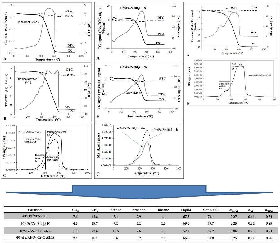
| Catalysts | Conv. (%) | SCO2 | SCH4 in HCs | SC2-C4 in HCs | SC5-C9 in HCs | SC10-C21 in HCs | Liquid | Paraffin/Olefins | Linear/Branched |
|---|---|---|---|---|---|---|---|---|---|
| 40%Fe/MWCNT | 71.1 | 7.6 | 14.3 | 5.9 | 13.0 | 66.8 | 67.5 | - | 4.3 |
| 40%Fe/Zeolite β-H | 75.7 | 4.5 | 18.4 | 5.6 | 44.5 | 31.5 | 69.6 | - | 18.2 |
| 40%Fe/Zeolite β-Na | 65.2 | 11.0 | 32.6 | 9.1 | 26.0 | 32.3 | 52.2 | - | 2.0 |
| 40%Fe/Al2O3-Cr2O3 (2:1) | 89.9 | 2.4 | 16.3 | 5.4 | 17.4 | 60.9 | 66.6 | 17.2 | 4.3 |
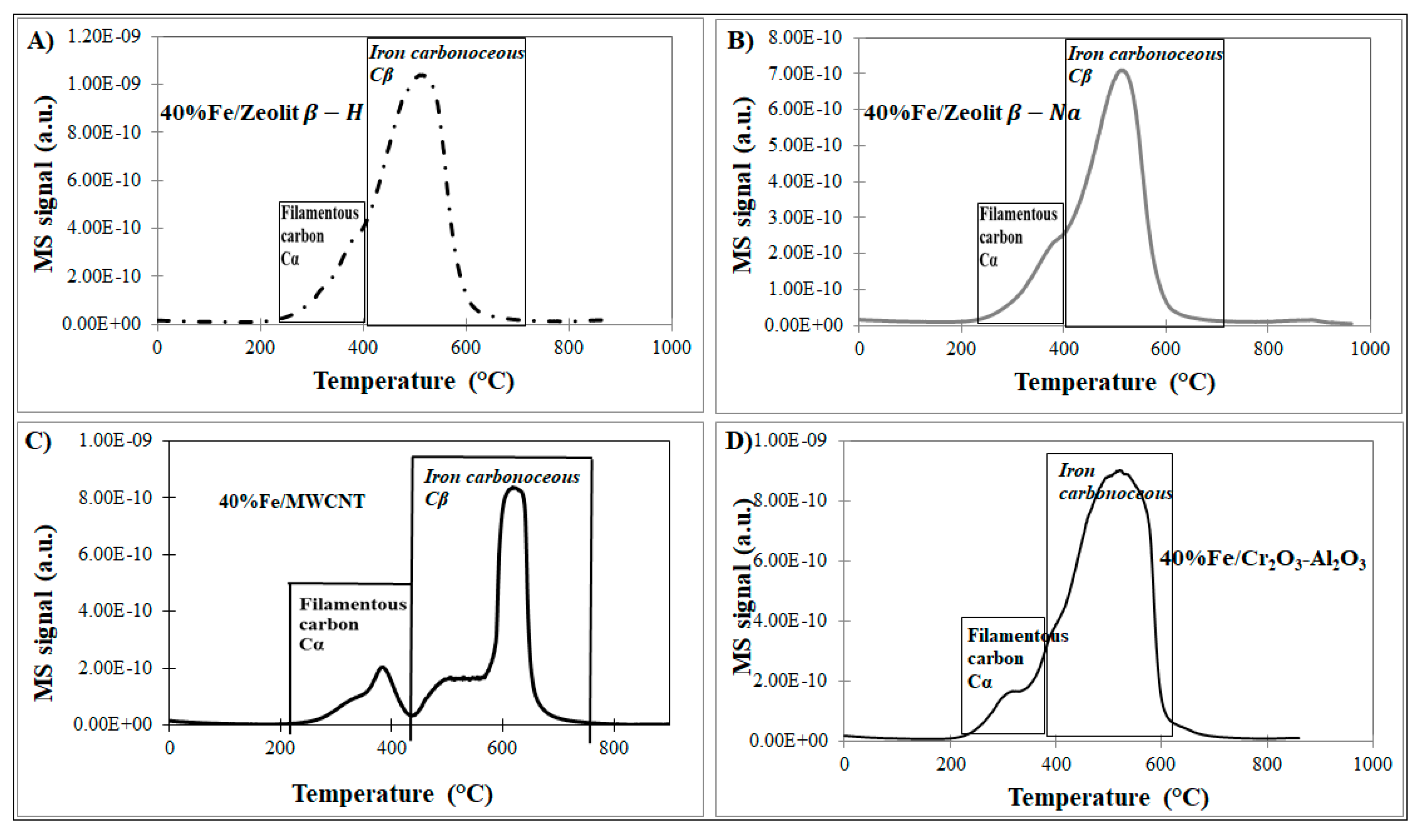
| Catalyst | Amount of Carbon Deposition (%) |
|---|---|
| 40%Fe/H-zeolite | 36.50 |
| 40%Fe/Na-zeolite | 31.20 |
| 40%Fe/MWCNT | 47.11 |
| 40%Fe/MWCNT (after reaction) | 67.22 (20.11 *) see Figure S2 |
| 40%Fe/Cr2O3-Al2O3 | 23.45 |
| Catalyst | Specific Surface Area (m2∙g−1) | Average Pore Radius (nm) |
|---|---|---|
| 40%Fe/MWCNT | 217 | 9.3 |
| 40%Fe/Zeolite β-H | 256 | 4.5 |
| 40%Fe/Zeolite β-Na | 278 | 4.2 |
| 40%Fe/Al2O3-Cr2O3 (2:1) | 118 | 2.6 |
| Catalysts/Supports | Weak Centres (mmol g−1) | Medium Centres (mmol∙g−1) | Strong Centres (mmol∙g−1) | The Total Amount of Desorbed NH3 (mmol∙g−1) |
|---|---|---|---|---|
| 40%Fe/Al2O3-Cr2O3 (2:1) | 0.07 | 0.09 | 0.09 | 0.25 |
| 40%Fe/Zeolite β-H | 0.22 | 0.11 | 0.07 | 0.40 |
| 40%Fe/Zeolite β-Na | 0.34 | 0.23 | 0.08 | 0.65 |
| 40%Fe/MWCNT | 0.03 | 0.73 | 0.22 | 0.98 |
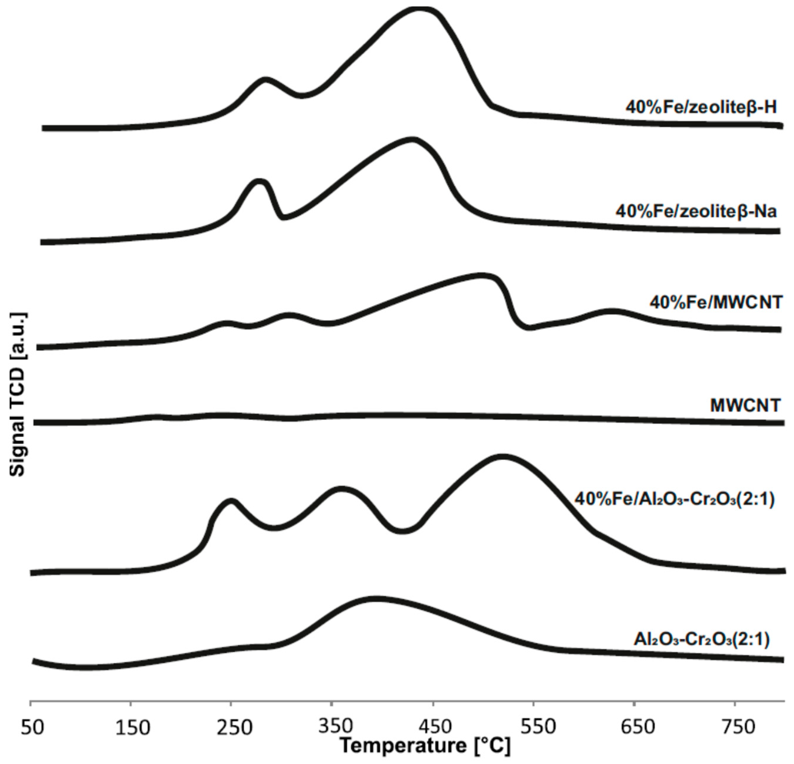
| Catalysts | Total Basicity (mmol∙g−1) |
|---|---|
| 40%Fe/Al2O3Cr2O3 (2:1) | 1.16 |
| 40%Fe/Zeolite-H | 1.10 |
| 40%Fe/Zeolite-Na | 0.91 |
| 40%Fe/MWCNT | 1.32 |
© 2019 by the authors. Licensee MDPI, Basel, Switzerland. This article is an open access article distributed under the terms and conditions of the Creative Commons Attribution (CC BY) license (http://creativecommons.org/licenses/by/4.0/).
Share and Cite
Mierczynski, P.; Dawid, B.; Chalupka, K.; Maniukiewicz, W.; Witoska, I.; Vasilev, K.; Szynkowska, M.I. Comparative Studies of Fischer-Tropsch Synthesis on Iron Catalysts Supported on Al2O3-Cr2O3 (2:1), Multi-Walled Carbon Nanotubes or BEA Zeolite Systems. Catalysts 2019, 9, 605. https://doi.org/10.3390/catal9070605
Mierczynski P, Dawid B, Chalupka K, Maniukiewicz W, Witoska I, Vasilev K, Szynkowska MI. Comparative Studies of Fischer-Tropsch Synthesis on Iron Catalysts Supported on Al2O3-Cr2O3 (2:1), Multi-Walled Carbon Nanotubes or BEA Zeolite Systems. Catalysts. 2019; 9(7):605. https://doi.org/10.3390/catal9070605
Chicago/Turabian StyleMierczynski, Pawel, Bartosz Dawid, Karolina Chalupka, Waldemar Maniukiewicz, Izabela Witoska, Krasimir Vasilev, and Malgorzta I. Szynkowska. 2019. "Comparative Studies of Fischer-Tropsch Synthesis on Iron Catalysts Supported on Al2O3-Cr2O3 (2:1), Multi-Walled Carbon Nanotubes or BEA Zeolite Systems" Catalysts 9, no. 7: 605. https://doi.org/10.3390/catal9070605
APA StyleMierczynski, P., Dawid, B., Chalupka, K., Maniukiewicz, W., Witoska, I., Vasilev, K., & Szynkowska, M. I. (2019). Comparative Studies of Fischer-Tropsch Synthesis on Iron Catalysts Supported on Al2O3-Cr2O3 (2:1), Multi-Walled Carbon Nanotubes or BEA Zeolite Systems. Catalysts, 9(7), 605. https://doi.org/10.3390/catal9070605