Computational Investigation of Nickel-Mediated B–H Activation and Regioselective Cage B–C(sp2) Coupling of o-Carborane


Abstract
:
1. Introduction
2. Computational Details
3. Results and Discussion
3.1. Mechanism
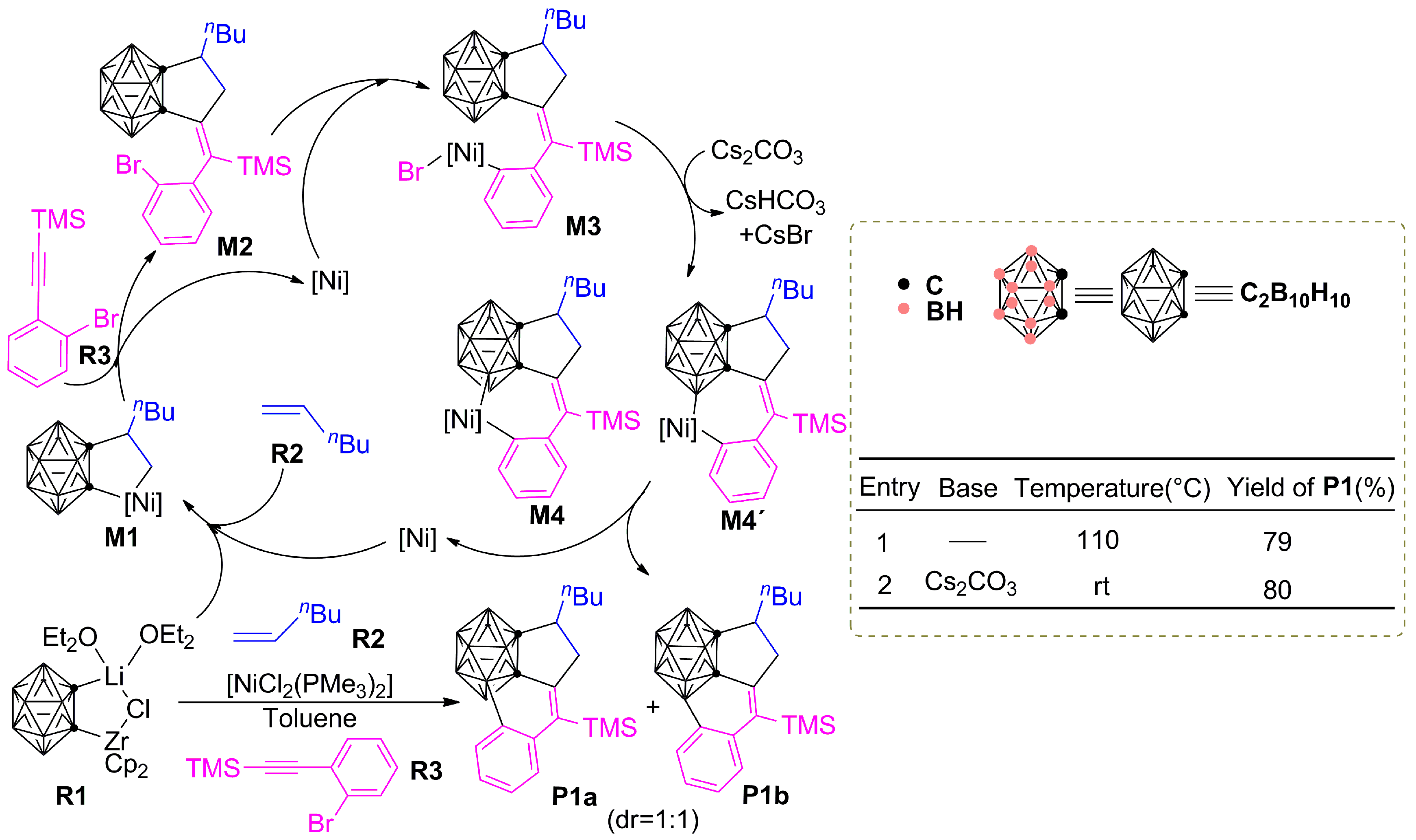
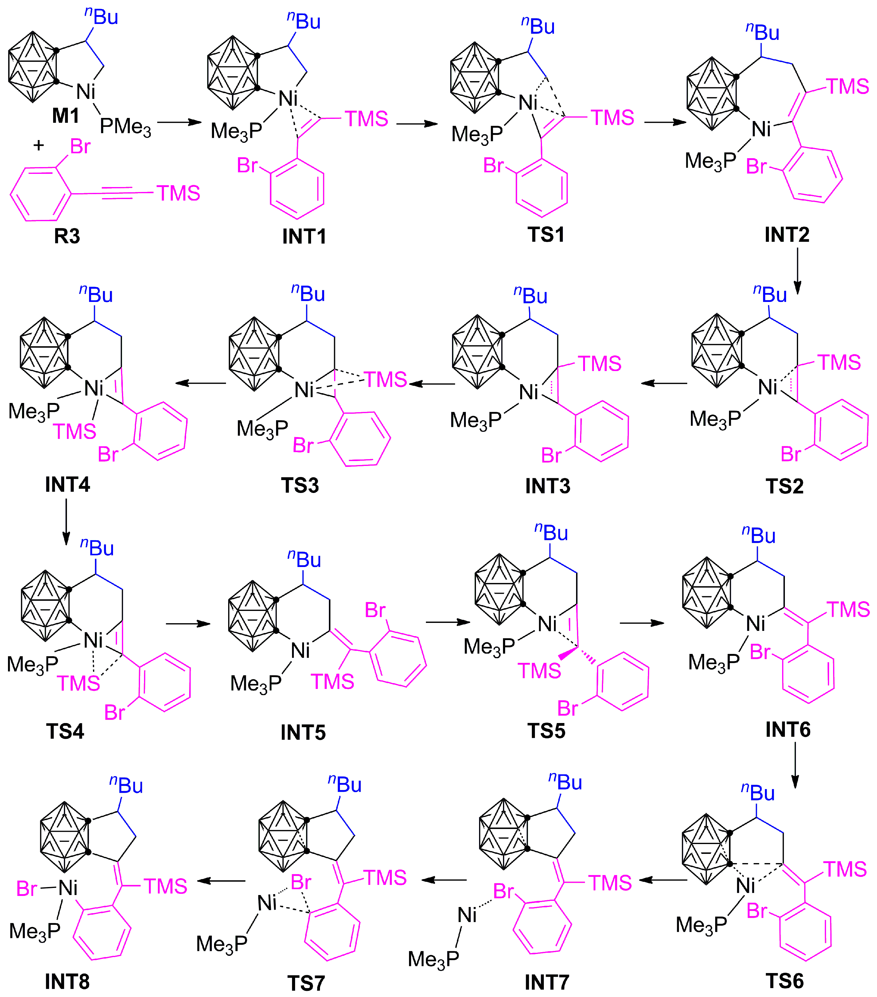
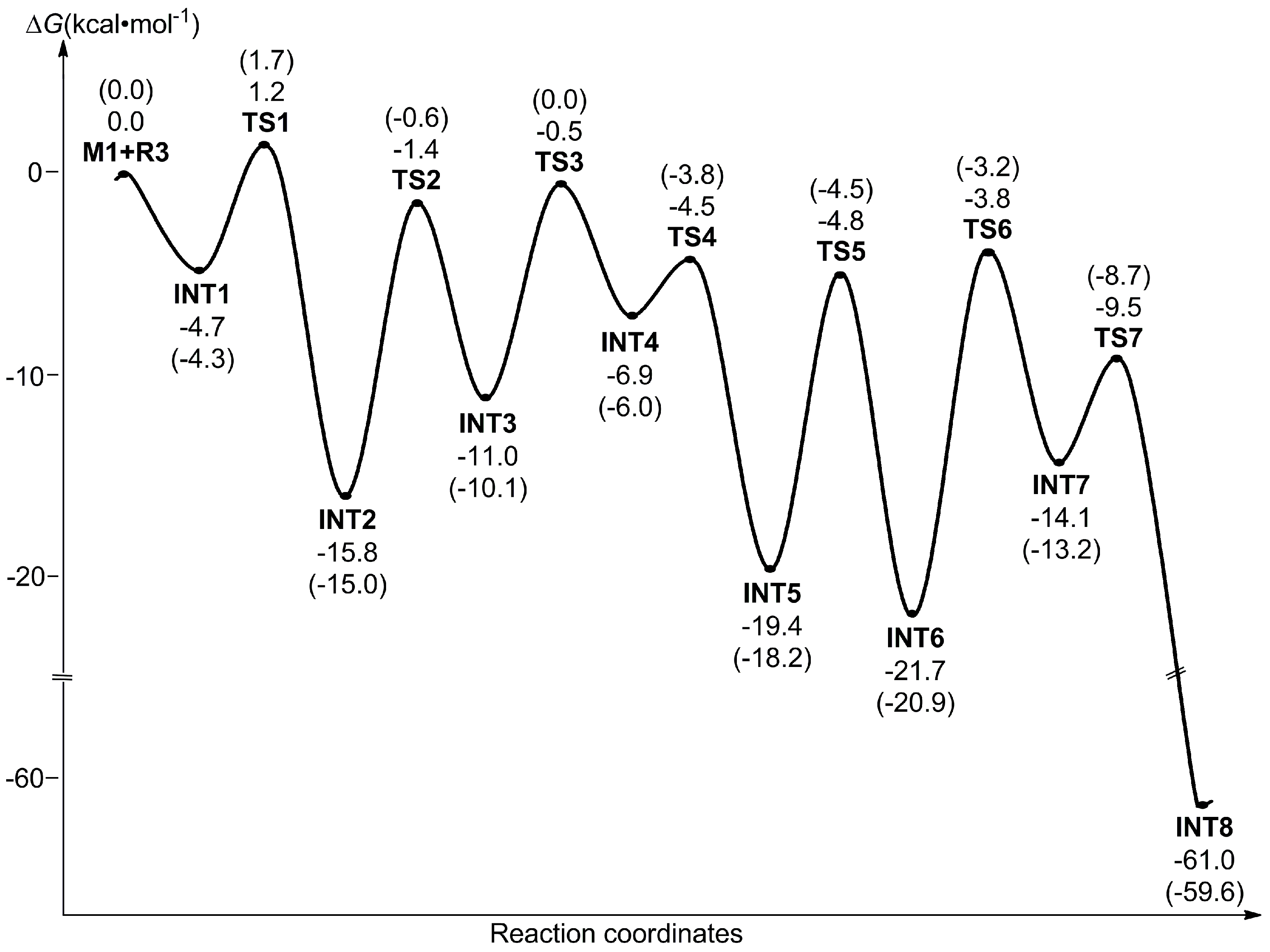
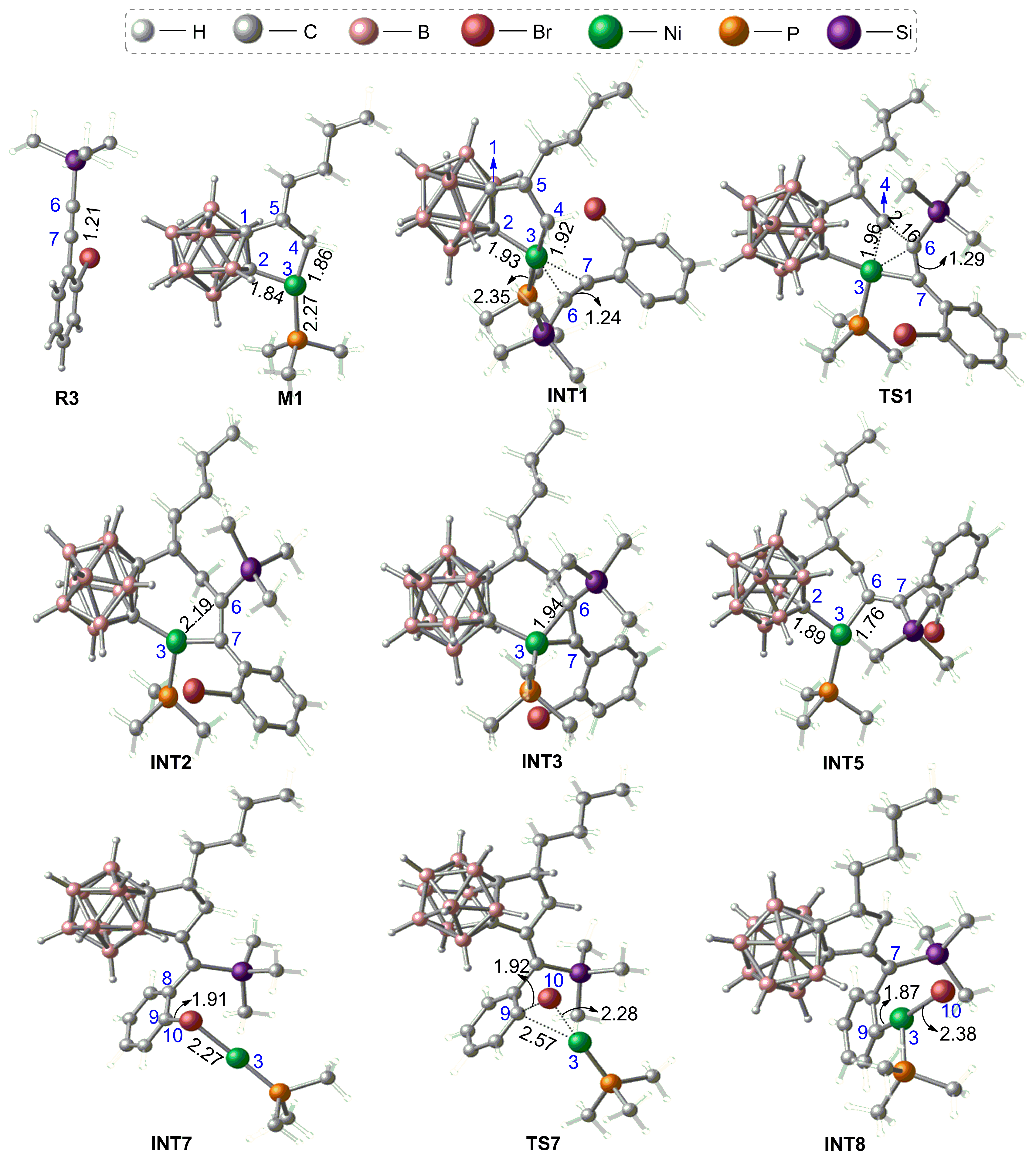
3.1.1. Formation Mechanism of Dihydrofulvenocarborane Intermediate INT8
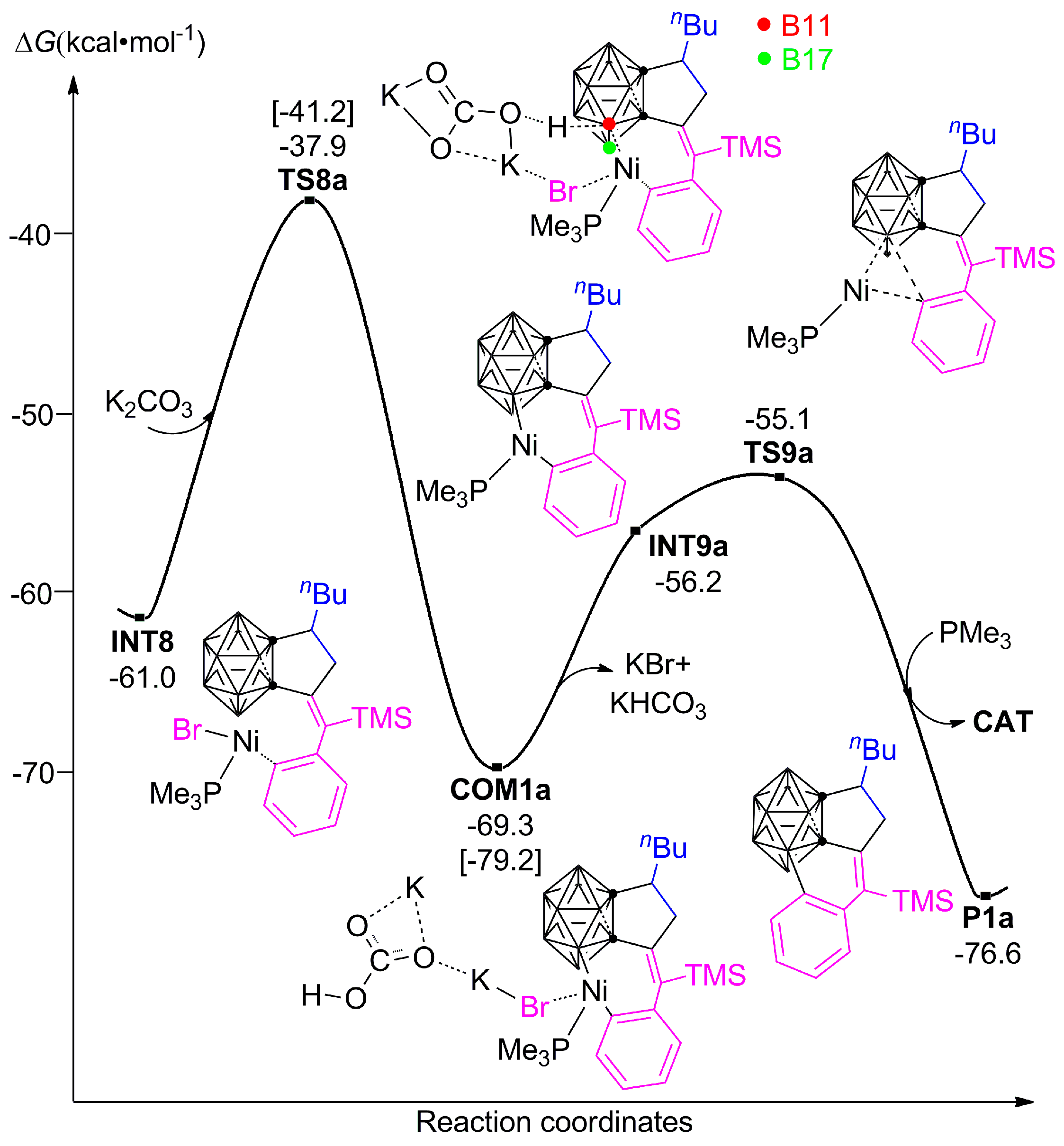
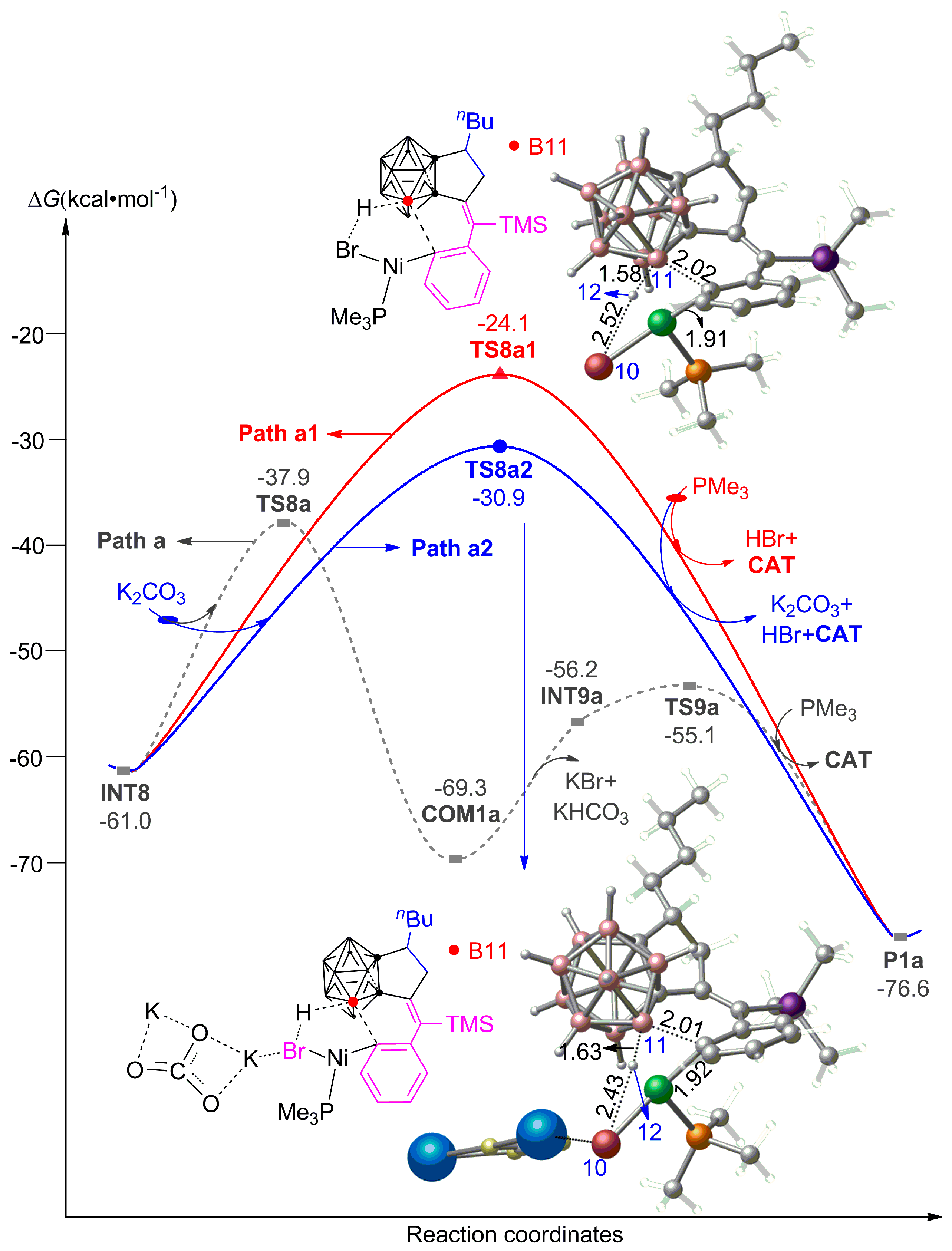
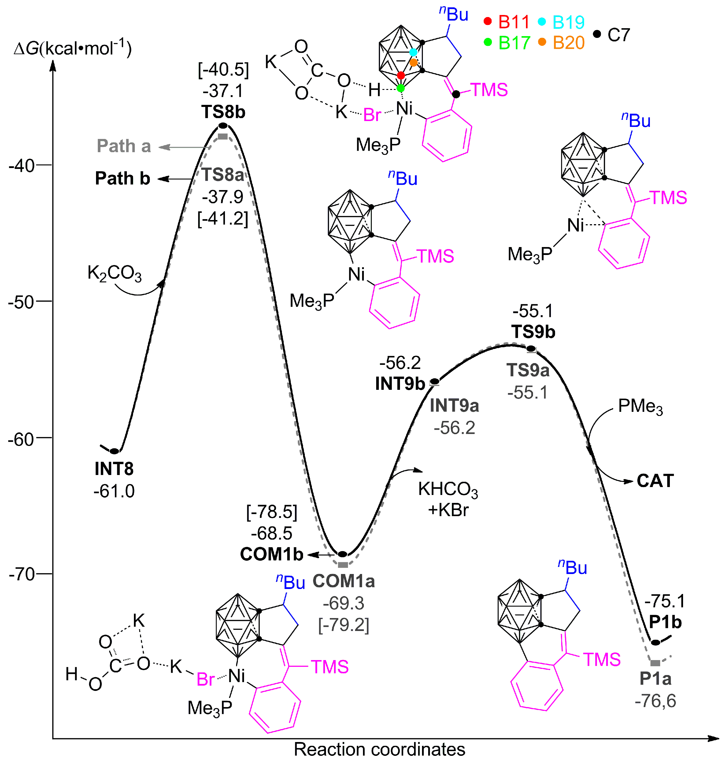
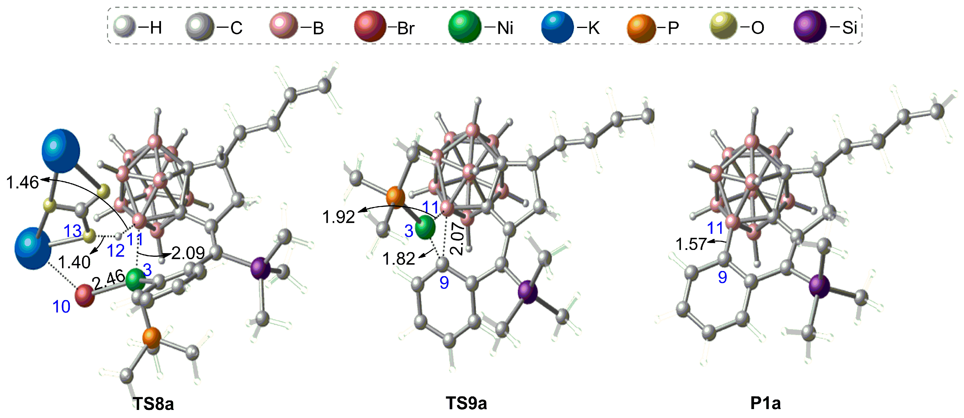
3.1.2. Mechanism of B–H Activation and Cage B–C(sp2) Coupling of o-Carborane
3.2. The Role of Cs2CO3 Additive
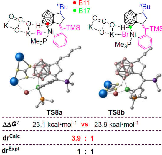
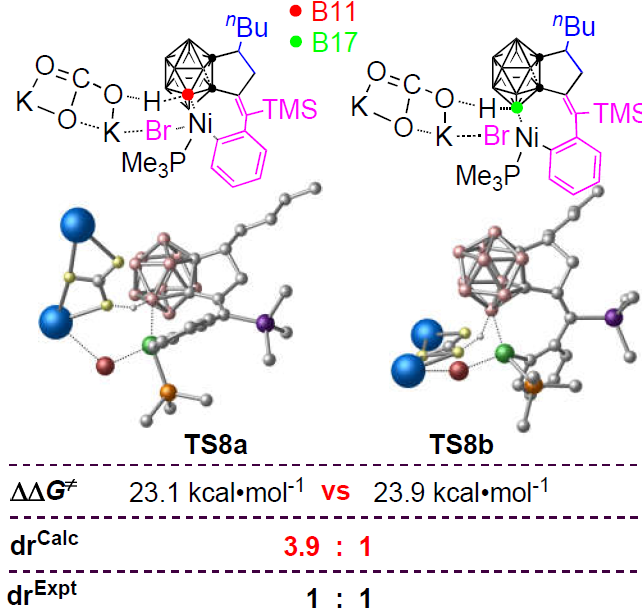
3.3. Diastereoselectivity of B–H Activation of o-Carborane
4. Conclusions
Supplementary Materials
Author Contributions
Acknowledgments
Conflicts of Interest
References
- Chen, G.; Yang, J.; Lu, G.; Liu, P.C.; Chen, Q.; Xie, Z.; Wu, C. One Stone Kills Three Birds: Novel Boron-Containing Vesicles for Potential BNCT, Controlled Drug Release, and Diagnostic Imaging. Mol. Pharm. 2014, 11, 3291–3299. [Google Scholar] [CrossRef] [PubMed]
- Guo, J.; Liu, D.; Zhang, J.; Zhang, J.; Miao, Q.; Xie, Z. o-Carborane Functionalized Pentacenes: Synthesis, Molecular Packing and Ambipolar Organic Thin-film Transistors. Chem. Commun. 2015, 51, 12004–12007. [Google Scholar] [CrossRef] [PubMed]
- Jin, G.F.; Hwang, J.-H.; Lee, J.-D.; Wee, K.-R.; Suh, I.-H.; Kang, S.O. A Three-Dimensional π-Electron Acceptor, Tri-Phenyl-o-Carborane, Bearing a Rigid Conformation with End-On Phenyl Units. Chem. Commun. 2013, 49, 9398–9400. [Google Scholar] [CrossRef] [PubMed]
- Cioran, A.M.; Musteti, A.D.; Teixidor, F.; Krpetic, Ž.; Prior, I.A.; He, Q.; Kiely, C.J.; Brust, M.; Viñas, C. Mercaptocarborane-Capped Gold Nanoparticles: Electron Pools and Ion Traps with Switchable Hydrophilicity. J. Am. Chem. Soc. 2012, 134, 212–221. [Google Scholar] [CrossRef] [PubMed]
- Scholz, M.; Hey-Hawkins, E. Carbaboranes as Pharmacophores: Properties, Synthesis, and Application Strategies. Chem. Rev. 2011, 111, 7035–7062. [Google Scholar] [CrossRef] [PubMed]
- Jude, H.; Disteldorf, H.; Fischer, S.; Wedge, T.; Hawkridge, A.M.; Arif, A.M.; Hawthorne, M.F.; Muddiman, D.C.; Stang, P.J. Coordination-Driven Self-Assemblies with a Carborane Backbone. J. Am. Chem. Soc. 2005, 127, 12131–12139. [Google Scholar] [CrossRef]
- Grimes, R.N. Carboranes in the Chemist’s Toolbox. Dalton Trans. 2015, 44, 5939–5956. [Google Scholar] [CrossRef]
- Qiu, Z.; Xie, Z. Generation and Reactivity of o-Carborynes. Dalton Trans. 2014, 43, 4925–4934. [Google Scholar] [CrossRef]
- Tang, C.; Xie, Z. Nickel-Catalyzed Cross-Coupling Reactions of o-Carboranyl with Aryl Iodides: Facile Synthesis of 1-Aryl-o-Carboranes and 1,2-Diaryl-o-Carboranes. Angew. Chem. Int. Ed. 2015, 54, 7662–7665. [Google Scholar] [CrossRef]
- Lyu, H.; Quan, Y.; Xie, Z. Palladium-Catalyzed Direct Dialkenylation of Cage B-H Bonds in o-Carboranes Through Cross-Coupling Reactions. Angew. Chem. Int. Ed. 2015, 54, 10623–10626. [Google Scholar] [CrossRef]
- Lyu, H.; Quan, Y.; Xie, Z. Transition Metal Catalyzed Direct Amination of the Cage B(4)-H Bond in o-Carboranes: Synthesis of Tertiary, Secondary, and Primary o-Carboranyl Amines. J. Am. Chem. Soc. 2016, 138, 12727–12730. [Google Scholar] [CrossRef] [PubMed]
- Lyu, H.; Quan, Y.; Xie, Z. Rhodium-Catalyzed Regioselective Hydroxylation of Cage B-H Bonds of o-Carboranes with O2 or Air. Angew. Chem. Int. Ed. 2016, 55, 11840–11844. [Google Scholar] [CrossRef] [PubMed]
- Quan, Y.; Xie, Z. Palladium-Catalyzed Regioselective Diarylation of o-Carboranes by Direct Cage B-H Activation. Angew. Chem. Int. Ed. 2016, 55, 1295–1298. [Google Scholar] [CrossRef] [PubMed]
- Zhao, D.; Xie, Z. Recent Advances in the Chemistry of Carborynes. Coordin. Chem. Rev. 2016, 314, 14–33. [Google Scholar] [CrossRef]
- Ren, S.; Qiu, Z.; Xie, Z. Transition-Metal-Promoted or -Catalyzed Exocyclic Alkyne Insertion via Zirconacyclopentene with Carborane Auxiliary: Formation of Symmetric or Unsymmetric Benzocarboranes. J. Am. Chem. Soc. 2012, 134, 3242–3254. [Google Scholar] [CrossRef] [PubMed]
- Ren, S.; Qiu, Z.; Xie, Z. Three-Component [2+2+2] Cycloaddition of Carboryne, Unactivated Alkene, and Alkyne via Zirconacyclopentane Mediated by Nickel: One-Pot Synthesis of Dihydrobenzocarboranes. Angew. Chem. Int. Ed. 2012, 51, 1010–1013. [Google Scholar] [CrossRef] [PubMed]
- Mu, W.-H.; Cheng, R.-J.; Fang, D.-C.; Chass, G.A. The Pivotal Role of Electronics in Preferred Alkene over Alkyne Ni-Carboryne Insertions and Absolute Regioselectivities. Dalton Trans. 2018, 47, 6494–6498. [Google Scholar] [CrossRef]
- Zhao, D.; Zhang, J.; Xie, Z. An Unprecedented Formal [5+2] Cycloaddition of Nitrones with o-Carboryne via Tandem [3+2] Cycloaddition/Oxygen Migration/Aromatization Sequence. J. Am. Chem. Soc. 2015, 137, 13938–13942. [Google Scholar] [CrossRef]
- Mu, W.-H.; Xia, S.-Y.; Li, J.-X.; Fang, D.-C.; Wei, G.; Chass, G.A. Competing Mechanisms, Substituent Effects, and Regioselectivities of Nickel-Catalyzed [2+2+2] Cycloaddition between Carboryne and Alkynes: A DFT Study. J. Org. Chem. 2015, 80, 9108–9117. [Google Scholar] [CrossRef]
- Zhang, J.; Quan, Y.; Lin, Z.; Xie, Z. Insight into Reaction Mechanism of [2+2+1] Cross-Cyclotrimerization of Carboryne with Alkene and Trimethylsilylarylalkyne Mediated by Nickel Complex. Organometallics 2014, 33, 3556–3563. [Google Scholar] [CrossRef]
- Huo, R.-P.; Guo, L.-H.; Zhang, F.-Q.; Zhang, X. Multiple Electronic State Mechanism for Carboryne Reaction with Benzene: A DFT Study. Int. J. Quantum Chem. 2017, 117, e25372. [Google Scholar] [CrossRef]
- Mu, W.H.; Ma, Y.; Fang, D.C.; Wang, R.; Zhang, H.N. Computational Insights into the Diels-Alder-alike Reactions of 1-Iodo-2-Lithio-o-Carborane with Fulvenes. Acta Chimica Sinica 2018, 76, 55–61. [Google Scholar] [CrossRef]
- Zhao, D.; Zhang, J.; Xie, Z. 1,3-Dehydro-o-Carborane: Generation and Reaction with Arenes. Angew. Chem. Int. Ed. 2014, 53, 8488–8491. [Google Scholar] [CrossRef] [PubMed]
- Qiu, Z.; Xie, Z. Palladium/Nickel-Cocatalyzed Cycloaddition of 1,3-Dehydro-o-Carborane with Alkynes. Facile Synthesis of C,B-Substituted Carboranes. J. Am. Chem. Soc. 2010, 132, 16085–16093. [Google Scholar] [CrossRef] [PubMed]
- Quan, Y.; Qiu, Z.; Xie, Z. Transition-Metal-Mediated Three-Component Cascade Cyclization: Selective Cage B-C(sp2) Coupling of Carborane with Aromatics and Synthesis of Carborane-Fused Tricyclics. J. Am. Chem. Soc. 2014, 136, 7599–7602. [Google Scholar] [CrossRef] [PubMed]
- Quan, Y.; Zhang, J.; Xie, Z. Three-Component [2+2+1] Cross-Cyclotrimerization of Carboryne, Unactivated Alkene, and Trimethylsilylalkyne Co-Mediated by Zr and Ni. J. Am. Chem. Soc. 2013, 135, 18742–18745. [Google Scholar] [CrossRef] [PubMed]
- Mu, W.-H.; Liu, W.-Z.; Cheng, R.-J.; Fang, D.-C. Electronic Effect-Guided, Palladium-Catalyzed Regioselective B-H Activation and Multistep Diarylation of o-Carboranes with Aryl Iodides. ACS Omega 2019, 4, 465–474. [Google Scholar] [CrossRef]
- Frisch, M.J.; Trucks, G.W.; Schlegel, H.B.; Scuseria, G.E.; Robb, M.A.; Cheeseman, J.R.; Scalmani, G.; Barone, V.; Mennucci, B.; Petersson, G.A.; et al. Gaussian 09, Revision D.01; Gaussian, Inc.: Wallingford, CT, USA, 2013. [Google Scholar]
- Tawada, Y.; Tsuneda, T.; Yanagisawa, S.; Yanai, T.; Hirao, K. A Long-range-corrected Time-dependent Density Functional Theory. J. Chem. Phys. 2004, 120, 8425–8433. [Google Scholar] [CrossRef]
- Vydrov, O.A.; Scuseria, G.E. Assessment of A Long Range Corrected Hybrid Functional. J. Chem. Phys. 2006, 125, 234109. [Google Scholar] [CrossRef]
- Yanai, T.; Tew, D.P.; Handy, N.C. A New Hybrid Exchange-correlation Functional Using the Coulomb-attenuating Method (CAM-B3LYP). Chem. Phys. Lett. 2004, 393, 51–57. [Google Scholar] [CrossRef]
- Lee, C.; Yang, W.; Parr, R.G. Development of the Colle-Salvetti Correlation-Energy Formula into a Functional of the Electron Density. Phys. Rev. B 1988, 37, 785–789. [Google Scholar] [CrossRef] [PubMed]
- Becke, A.D. Density-functional Thermochemistry. III. The Role of Exact Exchange. J. Chem. Phys. 1993, 98, 5648–5652. [Google Scholar] [CrossRef]
- Grimme, S.; Antony, J.; Ehrlich, S.; Krieg, H. A Consistent and Accurate Ab Initio Parametrization of Density Functional Dispersion Correction (DFT-D) for the 94 Elements H-Pu. J. Chem. Phys. 2010, 132, 154104. [Google Scholar] [CrossRef] [PubMed]
- Chai, J.-D.; Head-Gordon, M. Long-Range Corrected Hybrid Density Functionals with Damped Atom-Atom Dispersion Corrections. Phys. Chem. Chem. Phys. 2008, 10, 6615–6620. [Google Scholar] [CrossRef] [PubMed]
- Godbout, N.; Salahub, D.R.; Andzelm, J.; Wimmer, E. Optimization of Gaussian-type Basis Sets for Local Spin Density Functional Calculations. Part I. Boron Through Neon, Optimization Technique and Validation. Can. J. Chem. 1992, 70, 560–571. [Google Scholar] [CrossRef]
- Sosa, C.; Andzelm, J.; Elkin, B.C.; Wimmer, E.; Dobbs, K.D.; Dixon, D.A. A Local Density Functional Study of the Structure and Vibrational Frequencies of Molecular Transition-Metal Compounds. J. Phys. Chem. 1992, 96, 6630–6636. [Google Scholar] [CrossRef]
- Schäfer, A.; Horn, H.; Ahlrichs, R. Fully Optimized Contracted Gaussian-Basis Sets for Atoms Li to Kr. J. Chem. Phys. 1992, 97, 2571–2577. [Google Scholar] [CrossRef]
- Schäfer, A.; Huber, C.; Ahlrichs, R. Fully Optimized Contracted Gaussian-Basis Sets of Triple zeta Valence Quality for Atoms Li to Kr. J. Chem. Phys. 1994, 100, 5829–5835. [Google Scholar] [CrossRef]
- Gonzalez, C.; Schlegel, H.B. An Improved Algorithm for Reaction Path Following. J. Chem. Phys. 1989, 90, 2154–2161. [Google Scholar] [CrossRef]
- Gonzalez, C.; Schlegel, H.B. Reaction Path Following in Mass-Weighted Internal Coordinates. J. Phys. Chem. 1990, 94, 5523–5527. [Google Scholar] [CrossRef]
- Fukui, K. The Path of Chemical Reactions - the IRC Approach. Acc. Chem. Res. 1981, 14, 363–368. [Google Scholar] [CrossRef]
- Miertuš, S.; Scrocco, E.; Tomasi, J. Electrostatic Interaction of a Solute with a Continuum. A Direct Utilizaion of AB Initio Molecular Potentials for the Prevision of Solvent Effects. Chem. Phys. 1981, 55, 117–129. [Google Scholar] [CrossRef]
- York, D.M.; Karplus, M. A Smooth Solvation Potential Based on the Conductor-Like Screening Model. J. Phys. Chem. 1999, 103, 11060–11079. [Google Scholar] [CrossRef]
- Tao, J.-Y.; Mu, W.-H.; Chass, G.A.; Tang, T.-H.; Fang, D.-C. Balancing the Atomic Waistline: Isodensity-Based SCRF Radii for Main-Group Elements and Transition Metals. Int. J. Quantum Chem. 2013, 113, 975–984. [Google Scholar] [CrossRef]
- Fang, D.-C. THERMO Program; Beijing Normal University: Beijing, China, 2013; This program can generate thermodynamic data in solution under given temperature, based on normally terminated Gaussian jobs with “freq” and “volume” keywords. [Google Scholar]
- Reed, A.E.; Curtiss, L.A.; Weinhold, F. Intermolecular Interactions from a Natural Bond Orbital, Donor-Acceptor Viewpoint. Chem. Rev. 1988, 88, 899–926. [Google Scholar] [CrossRef]
- Reed, A.E.; Weinstock, R.B.; Weinhold, F. Natural Population Analysis. J. Chem. Phys. 1985, 83, 735–746. [Google Scholar] [CrossRef]
- Carpenter, J.E.; Weinhold, F.J. Analysis of the Geometry of the Hydroxymethyl Radical by the “Different Hybrids for Different Spins” Natural Bond Orbital Procedure. J. Mol. Struc.-THEOCHEM 1988, 169, 41–62. [Google Scholar] [CrossRef]
- Hostaš, J.; Řezáč, J. Accurate DFT-D3 Calculations in a Small Basis Set. J. Chem. Theory Comput. 2017, 13, 3575–3585. [Google Scholar] [CrossRef]
- Masson-Makdissi, J.; Vandavasi, J.K.; Newman, S.G. Switchable Selectivity in the Pd-Catalyzed Alkylative Cross-Coupling of Esters. Org. let. 2018, 20, 4094–4098. [Google Scholar] [CrossRef]
- Kim, S.W.; Schwartz, L.A.; Zbieg, J.R.; Stivala, C.E.; Krische, M.J. Regio- and Enantioselective Iridium-Catalyzed Amination of Racemic Branched Alkyl-Substituted Allylic Acetates with Primary and Secondary Aromatic and Heteroaromatic Amines. J. Am. Chem. Soc. 2019, 141, 671–676. [Google Scholar] [CrossRef]
- Dong, C.-C.; Xiang, J.-F.; Xu, L.-J.; Gong, H.-Y. From CO2 to 4H-Quinolizin-4-ones: A One-Pot Multicomponent Approach via Ag2O/Cs2CO3 Orthogonal Tandem Catalysis. J. Org. Chem. 2018, 83, 9561–9567. [Google Scholar] [CrossRef] [PubMed]
- Koga, Y.; Kaneda, T.; Saito, Y.; Murakami, K.; Itami, K. Synthesis of Partially and Fully Fused Polyaromatics by Annulative Chlorophenylene Dimerization. Science 2018, 359, 435–439. [Google Scholar] [CrossRef]
- Swyka, R.A.; Zhang, W.; Richardson, J.; Ruble, J.C.; Krische, M.J. Rhodium-Catalyzed Aldehyde Arylation via Formate-Mediated Transfer Hydrogenation: Beyond Metallic Reductants in Grignard/Nozaki-Hiyami-Kishi-Type Addition. J. Am. Chem. Soc. 2019, 141, 1828–1832. [Google Scholar] [CrossRef] [PubMed]
- Baker, J.; Scheiner, A.; Andzelm, J. Spin contamination in density functional theory. Chem. Phys. Lett. 1993, 216, 380–388. [Google Scholar] [CrossRef]
- Quan, Y.; Xie, Z. Palladium-Catalyzed Regioselective Intramolecular Coupling of o-Carborane with Aromatics via Direct Cage B-H Activation. J. Am. Chem. Soc. 2015, 137, 3502–3505. [Google Scholar] [CrossRef] [PubMed]
- Ding, L.; Ishida, N.; Murakami, M.; Morokuma, K. Sp3-sp2 vs. sp3-sp3 C-C Site Selectivity in Rh-Catalyzed Ring Opening of Benzocyclobutenol: A DFT Study. J. Am. Chem. Soc. 2014, 136, 169–178. [Google Scholar] [CrossRef] [PubMed]
- Li, Y.; Fang, D.-C. DFT Calculations on Kinetic Data for Some [4+2] Reactions in Solution. Phys. Chem. Chem. Phys. 2014, 16, 15224–15230. [Google Scholar] [CrossRef] [PubMed]
- Armstrong, A.; Boto, R.A.; Dingwall, P.; Contreras-Garcia, J.; Harvey, M.J.; Mason, N.J.; Rzepa, H.S. The Houk-List transition States for Organocatalytic Mechanisms Revisited. Chem. Sci. 2014, 5, 2057–2071. [Google Scholar] [CrossRef]
- Fuentealba, P.; Preuss, H.; Stoll, H.; Szentpály, L.V. A Proper Account of Core-polarization with Pseudopotentials: Single Valence-Electron Alkali Compounds. Chem. Phys. Lett. 1982, 89, 418–422. [Google Scholar] [CrossRef]


 | NBO charge | 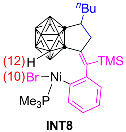 | |
| Br(10) | −0.480 | ||
| H(12) | +0.041 | ||
| O(13) | −1.055 | ||
| K(16) | +0.932 |
| Methods | LC-ωPBE | CAM-B3LYP | B3LYP | B3LYP-D3 | |
|---|---|---|---|---|---|
| Free-energy barriers (ΔΔG, kcal·mol−1) | TS8a | 23.1 | 24.8 | 26.7 | 15.2 |
| TS8b | 23.9 | 26.9 | 29.6 | 14.3 | |
| TS9a | 14.2 | 10.3 | 3.1 | 22.1 | |
| TS9b | 13.4 | 8.9 | 6.9 | 23.1 | |
| kRDS,a (L·mol−1·s−1) | 7.113 × 10⁻⁵ | 4.030 × 10⁻⁶ | 1.629 × 10⁻⁷ | 3.850 × 10⁻⁴ | |
| kRDS,b (L·mol−1·s−1) | 1.842 × 10⁻⁵ | 1.162 × 10⁻⁷ | 1.216 × 10⁻⁹ | 7.113 × 10⁻⁵ | |
| t1/2,RDS,a (h) | 3.905 × 100 | 6.893 × 101 | 1.705 × 10³ | 5.002 × 10⁻¹ | |
| t1/2,RDS,b (h) | 1.508 × 101 | 2.390 × 10³ | 2.283 × 10⁵ | 2.707 × 100 | |
| drCalc. | 3.9:1 | 35:1 | 134:1 | 5.4:1 | |
| drExpt. | 1:1 | ||||
| Transition States | Free-energy Barriers (ΔΔG, kcal·mol−1) | |||
|---|---|---|---|---|
| LC-ωPBE | CAM-B3LYP | B3LYP | B3LYP-D3 | |
| TS1 | 5.9 | 12.2 | 19.1 | 10.8 |
| TS2 | 14.4 | 16.0 | 14.3 | 12.9 |
| TS3 | 10.5 | 14.9 | 15.6 | 15.2 |
| TS4 | 2.4 | 1.0 | 1.6 | 2.1 |
| TS5 | 14.6 | 18.8 | 19.3 | 17.7 |
| TS6 | 17.9 | 23.9 | 22.3 | 22.4 |
| TS7 | 4.6 | 5.4 | 4.7 | 2.1 |
© 2019 by the authors. Licensee MDPI, Basel, Switzerland. This article is an open access article distributed under the terms and conditions of the Creative Commons Attribution (CC BY) license (http://creativecommons.org/licenses/by/4.0/).
Share and Cite
Mu, W.-H.; Liu, W.-Z.; Cheng, R.-J.; Dou, L.-J.; Liu, P.; Hao, Q. Computational Investigation of Nickel-Mediated B–H Activation and Regioselective Cage B–C(sp2) Coupling of o-Carborane. Catalysts 2019, 9, 548. https://doi.org/10.3390/catal9060548
Mu W-H, Liu W-Z, Cheng R-J, Dou L-J, Liu P, Hao Q. Computational Investigation of Nickel-Mediated B–H Activation and Regioselective Cage B–C(sp2) Coupling of o-Carborane. Catalysts. 2019; 9(6):548. https://doi.org/10.3390/catal9060548
Chicago/Turabian StyleMu, Wei-Hua, Wen-Zhu Liu, Rui-Jiao Cheng, Li-Juan Dou, Pin Liu, and Qiang Hao. 2019. "Computational Investigation of Nickel-Mediated B–H Activation and Regioselective Cage B–C(sp2) Coupling of o-Carborane" Catalysts 9, no. 6: 548. https://doi.org/10.3390/catal9060548
APA StyleMu, W.-H., Liu, W.-Z., Cheng, R.-J., Dou, L.-J., Liu, P., & Hao, Q. (2019). Computational Investigation of Nickel-Mediated B–H Activation and Regioselective Cage B–C(sp2) Coupling of o-Carborane. Catalysts, 9(6), 548. https://doi.org/10.3390/catal9060548