Article

Preparation of Metal Amalgam Electrodes and Their Selective Electrocatalytic CO2 Reduction for Formate Production

1
Center for Clean Energy and Chemical Engineering, Korea Institute of Science and Technology, Hwarang no 14-gil 5, Seongbuk-gu, Seoul 136-791, Korea
2
Clean Energy and Chemical Engineering, University of Science and Technology, 217 Gajeong-ro Yuseong, Daejeon 34113, Korea
*
Author to whom correspondence should be addressed.
Catalysts 2019, 9(4), 367; https://doi.org/10.3390/catal9040367
Submission received: 28 March 2019 / Revised: 15 April 2019 / Accepted: 16 April 2019 / Published: 18 April 2019
(This article belongs to the Special Issue Catalysis and Catalytic Processes for CO2 Conversion)

Abstract

:
Electrochemical CO2 reduction to produce formate ions has studied for the sustainable carbon cycle. Mercury in the liquid state is known to be an active metallic component to selectively convert CO2 to formate ions, but it is not scalable to use as an electrode in electrochemical CO2 reduction. Therefore, scalable amalgam electrodes with different base metals are tested to produce formate by an electrochemical CO2 reduction. The amalgam electrodes are prepared by the electrodeposition of Hg on the pre-electrodeposited Pd, Au, Pt and Cu nanoparticles on the glassy carbon. The formate faradaic efficiency with the Pd, Au, Pt and Cu is lower than 25%, while the one with the respective metal amalgams is higher than 50%. Pd amalgam among the tested samples shows the highest formate faradic efficiency and current density. The formate faradaic efficiency is recorded 85% at −2.1 V vs SCE and the formate current density is −6.9 mA cm−2. It is concluded that Pd2Hg5 alloy on the Pd amalgam electrode is an active phase for formate production in the electrochemical CO2 reduction.

1. Introduction

Fossil fuels have been the main source of energy [1]. Continuous CO2 emission from fossil fuels is the main cause of climate change [2]. CO2 utilization can provide not only a sustainable way to mitigate CO2 but also provide a practical solution for energy storage from renewable energy sources [3,4]. CO2 can be converted to useful fuels and chemicals by an electrochemical method at standard temperature and pressure (STP) [5]. Furthermore, the electrochemical method is more controllable and scalable [6]. Therefore, selective electrocatalytic reduction of CO2 to formate has been studied as it is easy to handle, non-corrosive, non-toxic and stable [7]. While formate or formic acid is used in the agriculture industry presently, it is considered a hydrogen source for fuel cell in future [4].
Normally, products in the electrochemical CO2 reduction are dependent on a type of catalyst, electrolyte, temperature, pressure and applied overpotential. H2 is usually produced as a main side reaction in the preparation of formate, resulting in low faradic efficiency [8]. A few catalytic components such as Sn, Pb and Bi are often chosen for their capability to catalyze CO2 to formate but they require high overpotential [9,10,11]. Hg has also been reported as a good catalytic component for the CO2 reduction to formate with 100% faradic efficiency in neutral aqueous electrolytes [12]. Hori and Suzuki revealed that the selectivity to a current density of formate at Hg electrode was independent of pH and the current density remains 0.5 mA·cm−2 [13]. As Hg is in a liquid state at STP, a dropping mercury electrode (DME), static mercury drop electrode (SMDE) or hanging drop mercury electrode (HDME) has been used in the electrochemistry [14]. Unfortunately, these electrodes are not scalable to use as an electrode for the electrochemical reaction for the mass production [15]. Therefore, the development of solid electrodes, keeping the best features of Hg, is required for the practical application. For the purpose, solid amalgam electrodes are explored to produce formate by an electrochemical CO2 reduction [16]. It was shown that mercury thin layers can be electrodeposited on metal foils such as Pt, Pd, Ir, Cu and Ag [17,18,19]. The electrochemical CO2 reduction was performed with Cu amalgam at 1 atm and the total current density of −200 mA·cm−2 with the formate efficiency of 12.9% was reported without the information about the applied potential [20].
In this work, CO2 reduction was investigated on Pd amalgam/GC (Pd2Hg5), Pt amalgam/GC (PtHg4), Au amalgam/GC (Au0.82Hg0.18) and Cu amalgam/GC electrodes (CuHg). Firstly, Pd, Pt, Au and Cu nanoparticles were electrodeposited on GC (glassy carbon) and, secondly, Hg was electrodeposited on the prepared Pd/GC, Pt/GC, Au/GC and Cu/GC electrodes. Their selectivity and catalytic activity for CO2 reduction to formate were examined in the applied potential ranges vs. SCE from −1.7 V to −2.3 V. Pd2Hg5 among the prepared metal amalgam electrodes exhibited the highest current density and selectivity towards the formate production.

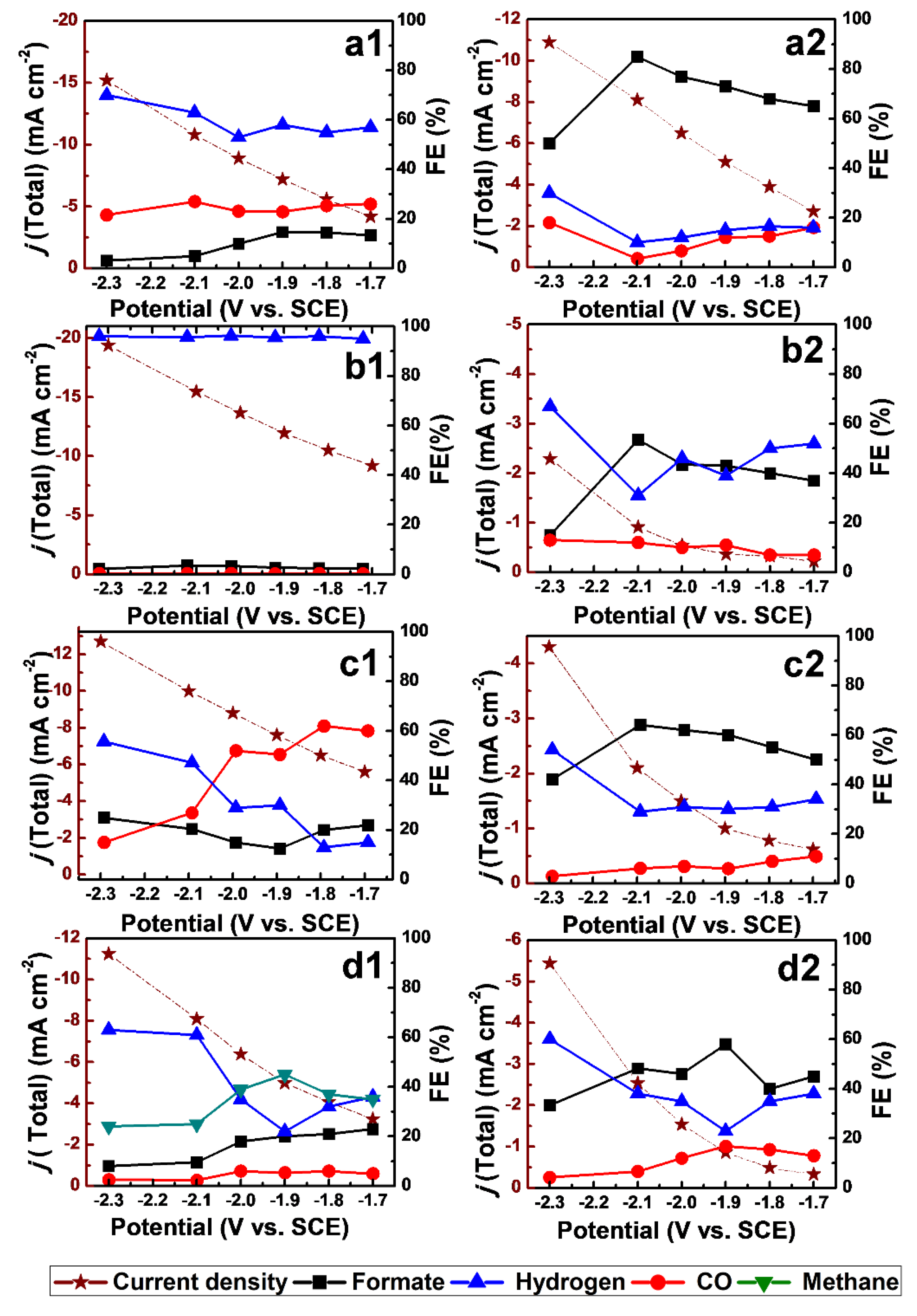
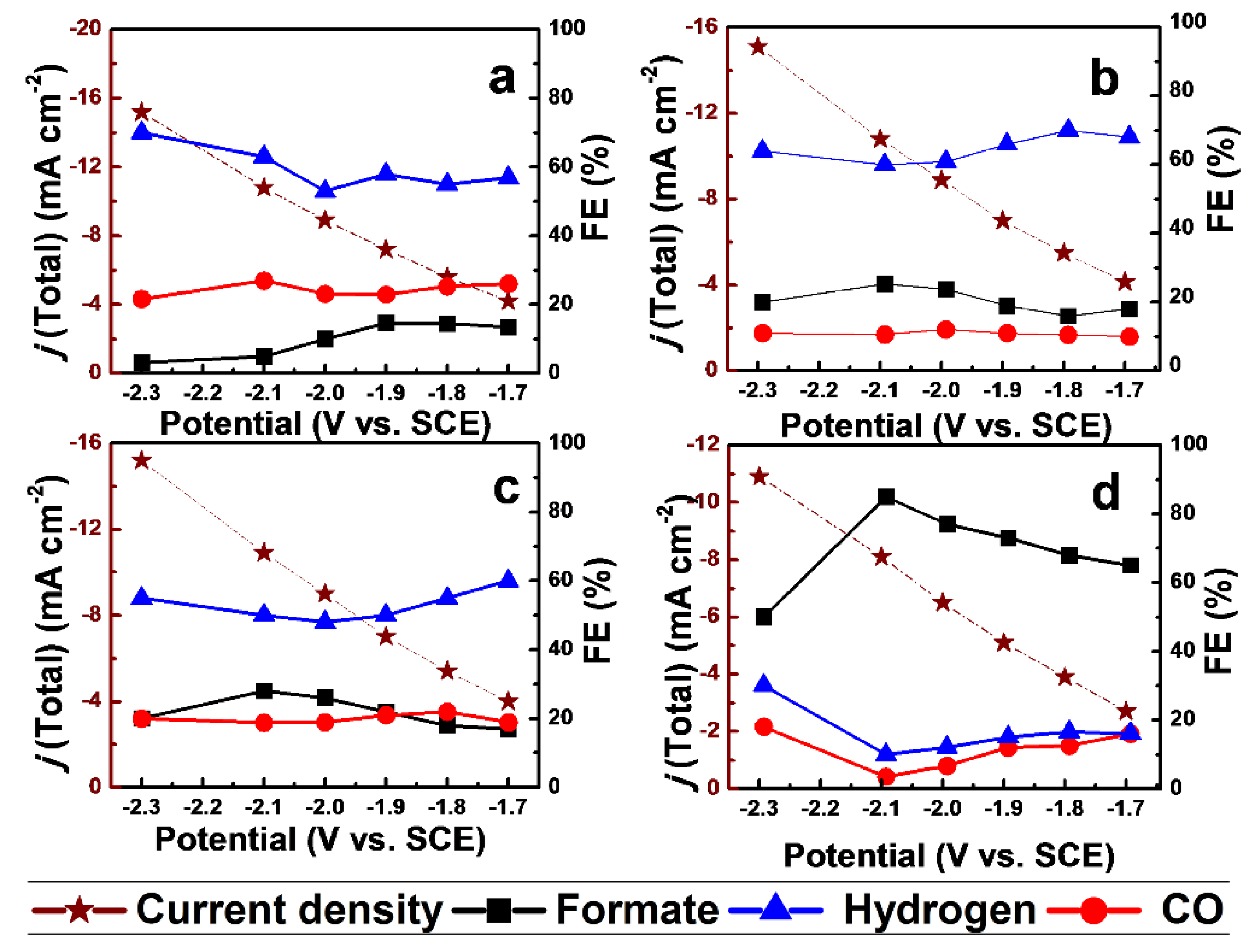
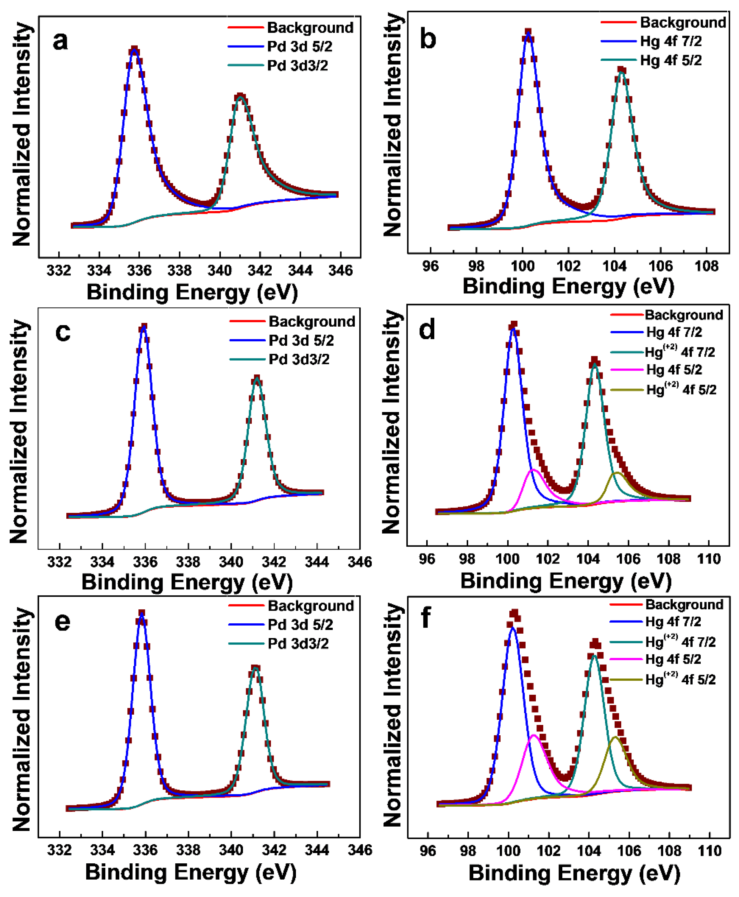
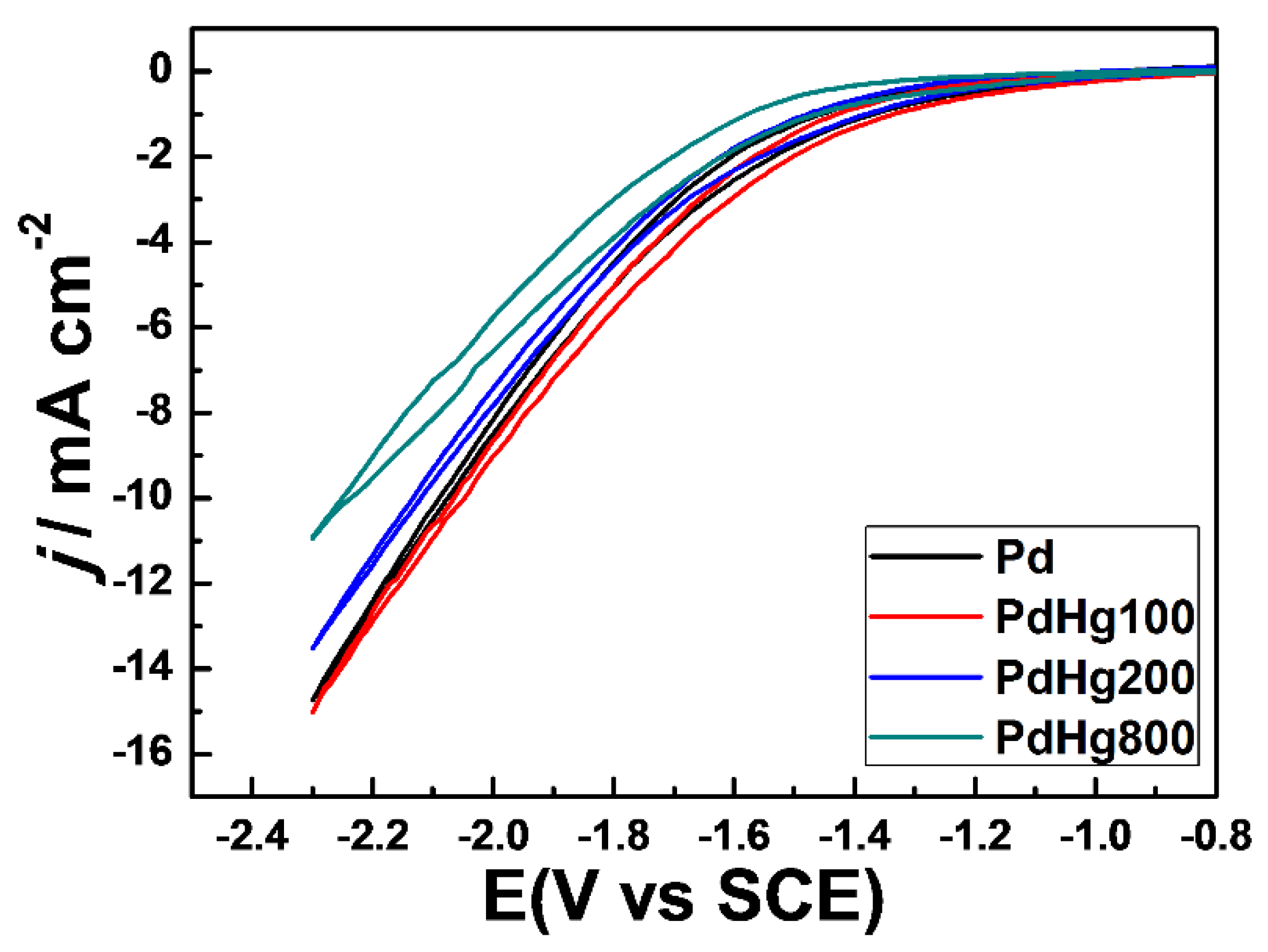
2. Results and Discussion

Figure 1a1–d1 shows SEM images of the prepared Pd, Au, Pt and Cu electrodes, respectively. The metal loading amount was estimated ca. 0.51 μmol cm−2 for each electrode. The Pd, Pt and Cu electrodes show that the metal nanoparticles are well dispersed on glassy carbon (GC). The metal particle size is listed in the order of Pd < Pt < Cu < Au. The Au electrode exhibits that the shape of Au particles is like a bloomy bud. When Hg was deposited on each metal electrode with the Hg/M atomic ratio of 8, the morphology of each metal particle abruptly changed as shown in Figure 1a2–d2. Pd amalgam on the PdHg800 electrode looks like liquid-like metal spread on GC and Pt amalgam on the electrode looks like a paste. It is interesting to see that Au amalgam and Cu amalgam on have a similar morphology compared to polygons.
X-ray diffraction analysis was conducted to observe the phases of metal nanoparticles and their transformation to amalgams. The phases of metal particles are clearly observable with the XRD patterns of Figure 2a1–d1, although the intensity of characteristic peaks of metal components is low. The XRD peak at the 2θ value of 40.2o corresponds to Pd(111) plane (JCPDS 87-0639) (Figure 2a1). The characteristic peaks of Au are observed at the 2θ values of 38.18 °, 44.4° and 64.57° on the Au electrode (Figure 2c1), which are corresponding to Au(111), Au(200) and Au(220) (JCPDS 040784), respectively. The peaks for (111) planes for the Pt and Cu electrodes are clearly observed, corresponding to JCPDS 87-0646 and JCPDS 851326, respectively. XRD patterns of Figure 2a2–a4 shows crystal structures of metal amalgams prepared at the Hg/M molar ratio of 8, which are corresponding to Pd2Hg5 (JCPDS 040046963), PtHg4 (JCPDS 040045447), Au0.82Hg0.18 (JCPDS 040035629) and CuHg (JCPDS 040812), respectively. Some extra peaks (noise peaks) are also observed, which are attributed to the elemental Hg [21,22]. Preparation of metal amalgam electrodes on the glassy carbon is presented in Table 1.
Electrochemical CO2 reduction on the surface of metal catalysts depends on many experimental factors such as crystal planes, surface modifications, particle size and morphology that lead to different reaction pathways resulting in different products [23]. Pd [24] and Au [25] have the high selectivity to CO, while Cu is identified to possess the high selectivity to hydrocarbons [26]. The catalytic activity of Pt [27] and Ni [28] for CO2 reduction is very low due to their optimum hydrogen adsorption energy for HER (hydrogen evolution reaction). The electrochemical CO2 reduction was performed with the prepared Pd (Pd/GC), Pt (Pt/GC), Au (Au/GC) and Cu (Cu/GC) electrode as shown in Figure 3a1–d1.
On the Pd electrode, it is observed that H2 is a major product, while the CO faradic efficiency is also found in the range of 20%–26%. Additionally, the formate efficiency is also observed in the range of 3%–15%. On the Pt electrode, the major product is hydrogen and CO is less than 0.1%, while a very small amount of formate is observed with the faradic efficiency of 1%. On the copper electrode, the main product is CH4 at −1.7 V. The CO faradic efficiency is also observed in the range of 2% to 6% in the applied potential range of −1.7−2.3 V. At the higher overpotential than −1.7 V, H2 is mainly produced. The CO2 reduction on the Au electrode exhibits the high selectivity to CO with the faradaic efficiency of 50%. As the applied potential is increased, the H2 faradic efficiency is enhanced. On the other hand, the formate faradic efficiency is also observed in the range of 12–22% during the reaction. It is shown that the reaction paths on each metal from the experimental results are not much different from the reported ones [29,30,31].
The total current density with each metal electrode is listed in the order of Pt > Pd > Au = Cu. The electrochemical CO2 reduction with the metal amalgam electrodes prepared at the Hg/M molar ratio of 8 is shown in Figure 3a2–d2. The total current density is low with the metal amalgam electrodes as compared with metallic electrodes. It should be noted that the total current density with PdHg800 is not so much low as compared with the Pd electrode. Figure 3a2 shows that the formate faradic efficiency is enhanced on the PdHg800 electrode, suppressing both H2 and CO production. The H2 faradic efficiency with PdHg800 is in the range of 10%–30% depending on the applied potential, while the CO faradaic efficiency is in the range of 3%–18%. The formate faradaic efficiency with PdHg800 increased with an increase in the applied potential and exhibits 85% at −2.1 V. The further increase in the applied potential rather decreased the formate faradic efficiency because it facilitated the production of CO and H2. It is clear that the formate current density with the PdHg800 electrode is higher than that with the Pd electrode. PtHg800 exhibits low total current density as compared with the Pt electrode. Nonetheless, the CO and formate current density with the PtHg800 electrode rather slightly increased as compared with the Pt electrode. On the other hand, the H2 current density with PtHg800 decreased a lot up to 30%–67% from ~95% with the Pt electrode. The CO current density with PtHg800 increased to 7%–13% from ca. 0.5% with the Pt electrode over the applied potential range. Formate became a major product with PtHg800. The formate faradic efficiency is observed 37% at −1.7 V, which increased with the applied potential exhibiting the highest value of 53.5% at a potential of −2.1 V. Then, it abruptly decreased to 15% at −2.3 V. The overall current density of PtHg800 is similar to that of AuHg800.
Au is known to be a catalyst to produce CO selectively as shown in Figure 3c1 [25]. In the case of AuHg800, the CO faradic efficiency was suppressed exhibiting high formate faradic efficiency, indicating that the reaction scheme was changed. The formate faradic efficiency on the AuHg800 electrode is in the range of 50%–64% at the applied potential of −1.7−2.1 V. The formate faradic efficiency with AuHg800 is the lowest at −2.3 V (42%). Copper has been known to produce hydrocarbon selectively as shown in Figure 3d1 [24]. The methane faradic efficiency, the main product with Cu/GC, is not detected with CuHg800. Formate faradaic efficiency is in the range of 40%–58% at the applied potential of −1.7−2.1 V, decreasing to 33% at −2.3 V. Maximum formate faradaic efficiency is observed as 58% at −1.9 V. CO faradaic efficiency is 13%–16% at the applied potential of −1.7−2.0 V, decreasing to 4.2% at −2.3 V.
It is clear to see that metal amalgams lose their intrinsic metal properties. All the prepared metal amalgam electrodes produce formate selectively and the selectivity to formate is depending on the capability to produce H2. H2 is selectively produced from the applied potential of −2.3 V. PdHg800 prevents H2 production the most, resulting in both the highest formate faradic efficiency and formate current density.
CV analysis was also conducted to examine the current density and the reduction behavior of CO2 with the metal amalgam electrodes as shown in Figure 4. PtHg800 shows the lowest current density in the CV analysis, while PdHg800 exhibits the highest current density. The onset potential of PdHg800 was much lower than that of PtHg800, AuHg800 and CuHg800. The current density from CV with the metal amalgam electrodes was well correlated with that from the electrochemical reduction reactions in Figure 3. The current density from CV with metal amalgam is listed in the order of PdHg800> CuHg > AuHg800 > PtHg800 at −2.3 V and of PdHg800 > AuHg800 > CuHg800 > PtHg800 at −1.7 V. The increase of the current density at the potential higher than −2.1 V can be attributed to H2 evolution due to limited solubility of the CO2. Solubility of CO2 in 0.1 M KHCO3 is 33 mM [9,31]. The CV patterns on metal amalgams are similar to that reported on Hg only [19], indicating that the reaction scheme on metal amalgam can be not much different from that on Hg. The intermediate of CO2 reduction is suggested to be CO2 [32]. On Hg, it was proposed that HCOO was generated as follows [23];
CO 2 + e CO 2
CO 2 + H + HCOO ·
HCOO · + e HCOO
The standard potential of CO2 is −2.09–2.14 V vs. SCE in aqueous media [33]. In this aspect, the formate faradic efficiency on Hg only abruptly increased from zero at −1.6 V to 80% at −1.7 V and increased further up to 90% at −2.0 V [19]. The formate faradic efficiency of 90% was maintained at the potential range of −2.0~3.0 V. On the other hand, the formate faradic efficiency was maximized at −2.1 V on Pd, Pt and Au metal amalgam and at −1.9 V on Cu amalgam. The CO faradic efficiency with Hg only was negligible even at −2.0 V, while CO with metal amalgam was significant at −1.7 V showing metallic character. CO production has been proposed via HCOO adsorption on metals such as Pd, Au, Ag and Cu [34].
C O 2 + H + + e +       H C O O
H C O O + H + + e   C O + H 2 O
C O       + C O
Therefore, the higher CO and H2 faradic efficiency with the metal amalgam than that with Hg only can be due to the retained metal character of metal amalgam. However, it is clear that Pd2Hg5 among the tested metal amalgams gave the highest formate faradic efficiency at −2.1 V (~85%) close to Hg only (~90%). For the optimization of Pd amalgam catalyst, Pd amalgam electrodes with different loadings of Hg (mercury) were prepared by adjusting deposition time at the current density of −1 mA·cm−2. The prepared Pd amalgam samples were named as PdHg100, PdHg200 and PdHg800 according to the molar ratio of Hg to Pd. Figure 5 shows faradic efficiencies of PdHg100, PdHg200 and PdHg800 at the different applied potentials. As previously described, the faradaic efficiency for hydrogen, CO and formate with the Pd/GC catalyst were observed in the range of 57%–70%, 2%0–26% and 3%–13% respectively. The formate faradaic efficiency with PdHg100 and PdHg200 increased a little and remained under 20% as compared with the Pd catalyst, while the H2 faradic efficiency was the highest. The formate faradic efficiency abruptly increased only with PdHg800 by suppressing the H2 production at −1.7 V. The formate faradic efficiency with PdHg800 was maximized 85% at −2.1 V, while the faradic efficiencies for CO and H2 were 3.5% and 10%, respectively.
In terms of the formate current density (Figure S2), the highest formate current density was −1.1 mA cm−2 at −1.9 V for Pd/GC, −3.0 mA cm−2 at −2.3 V for PdHg100, −3.1 mA cm−2 at −2.3 V for PdHg200, and −6.9 mA cm−2 at −2.1 V for PdHg800. The phase of PdHg800 alloy for all the prepared Pd amalgams was only observed by XRD analysis was Pd2Hg5 (Figure S3). The intensity of peaks of PdHg800 with the Pd amalgams increased with an increase in Hg content. Therefore, the isolated Pd should be present on PdHg100 and PdHg200 in the bulk phase, because the phase of Pd2Hg5 was only observed in XRD patterns (Figure S3). XPS analysis was also performed to examine the surface composition of PdHg100, PdHg200 and PdHg800 as shown in Figure 6, and Table 2. The B.E. energies of Pd(3d5/2) of PdHg100, PdHg200 and PdHg800 were 335.7, 335.9 and 335.8 8 eV, respectively, indicating that Pd on all the Pd amalgam samples was in the metallic state [34]. The double separation of Pd(3d5/2) and Pd(3d3/2) is 5.3 eV for all the samples. Hg with PdHg100 shows that Hg is in the metallic state, while one with PdHg200 and PdHg800 is in the state of Hg0 and Hg2+. The compositions of Hg2+ with PdHg200 and PdHg800 were 19.0 and 31%, respectively. Hg(4f7/2) and Hg(4f5/2) has a double separation of 4.0 eV [35]. The atomic ratios of PdHg100, PdHg200 and PdHg800 are 0.15, 1.28 and 2.48, respectively. The excess of Hg during the Hg electrodeposition was in the form of mercury sulfate, which was removed by applying a constant potential of −1.5 V for 10 min in 0.1M KHCO3 solution as described in the experimental. Therefore, XPS analysis indicates that Pd with PdHg100 (Hg/Pd = 0.15) and PdHg200 (Hg/Pd = 1.28) should also be in the isolated metallic state on the surface.
From the XRD and XPS analysis, low formate faradic efficiency is ascribed to the presence of isolated Pd, which can produce H2 selectively. SEM images (Figure S4) show that Pd amalgram coalesces via migration from metallic Pd during the Hg electrodeposition on Pd/GC as the amount of Hg deposition is increased. For the observation of Pd and Hg on GC, high-angle annular dark-field scanning transmission electron microscopy (HAADF-STEM) analysis was performed for PdHg800.
Figure 7 shows that Pd and Hg are completely miscible and uniform to facilitate to the XPS analysis. EDS quantitative analysis is also performed for PdHg100, PdHg200, PtHg800 and AuHg800 and shown in Figures S5 and S6. CV analysis with PdHg100, PdHg200 and PdHg800 were performed as shown in Figure 8. PdHg100 has a similar current density to the Pd electrode. On the other hand, the total current density for the PdHg electrodes with the atomic ratio of Hg/Pd more than 1.0 decreased with an increase in Hg content. The apparent surface area of PdHg100 was similar to that of the Pd electrode. On the other hand, the apparent surface area of PdHg electrodes decreased due to the coalescence with an increase in Hg content as represented in Figure S4. The reduction of the surface area might cause a lower total current density. Although the total current density was observed with the Pd electrode, PdHg800 with the nearly pure Pd2Hg5 alloy phase showed the highest formate current density with the highest formate faradic efficiency. From the experimental observations, it can be concluded that Pd amalgam among the tested Pd, Pt, Au and Cu amalgam is the best for the electrochemical CO2 reduction to formate and the Pd2Hg5 alloy is the active phase for the Pd amalgam electrode.

3. Materials and Methods

3.1. Materials

Hg(NO3)H2O (99.9%), PdCl2 (99.9%), K2PtCl4 (99.9%), HAuCl4 (99.9%) KHCO3 (99.9%) and aniline (99.5%) were purchased from Sigma-Aldrich Ltd. Co. Glassy carbon (GC) of different sizes was purchased from Dasomrms Ltd. Co. 1 M H2SO4 and 1 M HCl were purchased and further diluted to 0.1 M solutions. Electrolytes were made using distilled water. Electrolytes were purged with Ar or CO2 for 30 min to saturate the solution before the reaction.

3.2. Synthesis of Electrode

A thin layer of polyaniline was coated on GC by electropolymerization of aniline by applying three CV cycles in the range of 0 to 1 V vs Ag/AgCl in the solution of 0.1 M aniline in 0.5 M H2SO4 to enhance the attachment of metal particles on GC. The electrodeposition of Pd was carried out at −1 mA cm−2 for 100 s in the 1 M HCl solution of 0.01 M PdCl2. Deposition of Pt, Au and Cu was also conducted in the same procedure in the acidic solution of K2PtCl6 and Au (III). Hg was electrodeposited on the prepared metallic particles on GC at −1.0 mA·cm−2 for 800 s in a solution of 0.5 M H2SO4 and 0.01 M Hg(NO3)H2O. After the electrodeposition of Hg, mercury sulfate on metal amalgam electrodes formed during the electrodeposition was removed by applying a constant potential of −1.5 V vs Ag/AgCl for 10 min in 0.1 M KHCO3 solution. Finally, the metal amalgam electrodes were used for the electrochemical CO2 reduction after the prepared amalgam electrodes were washed out with distilled water. Before preparing electrodes, GC was washed with ethanol and D.I. water. To clean the electrode surface completely, 40 cycles of CV scanning is performed from −1.5 V to 1.5 V vs Ag/AgCl in 0.5 M H2SO4 at the scan rate of 100 mV·s−1.

3.3. Material Characterization and Product Analysis

Powder X-ray diffraction (XRD) was performed using a Bruker D8 advance, Germany), equipped with Cu Kα radiation (λ = 1.5406 Å). SEM images were recorded using FEI Nova Nano 200 (USA) (10 kV accelerating voltage). XPS analysis was performed on a PHI versaProbe (Ulvac-PHI), (Japan) with the background pressure of 2 × 10⁻⁷ Pa and the spot size of 100 μm × 100μm at an angle of 45°, wide scan pass energy of 46.95 eV. High-angle annular dark-field scanning transmission electron microscopy (HAADF-STEM) and TEM EDS analysis was performed at FEI Talos F200X at an accelerating voltage of 80–200 kV (USA). During the electrolysis, gaseous products were sampled from the electrochemical cell and analyzed using Younglin 6500 GC system equipped with RESTEK microsieve (RT-Msieve 5A) and a pulse discharged detector (PDD). The quantification of gas products was performed after the reaction of 60 min. He with ultra-high purity (99.9999%) was used as a carrier gas. Quantification of the liquid products was performed on (IC25-Dionex) ion chromatograph (USA). The column was an IonPac AS19 using 0.02 mol L−1 NaOH at the mobile phase rate of 1 mL min−1. During the measurement, a current was kept at 60 mA.

3.4. Electrochemical Characterization

Cyclic voltammetry experiments were carried out in a standard three-electrode cell assembly. A saturated calomel electrode (SCE) and a Pt foil were used as a reference electrode and a counter electrode, respectively. The CO2 reduction was carried out in a custom made two-compartment cell separated by a Nafion 115 membrane. Each cell compartment contained 20 mL of 0.1 M KHCO3 electrolyte. CO2 was purged through the electrolyte at 10 mL min−1 before the reaction. Here, the applied potential for the electrochemical CO2 reduction is referenced with SCE (saturated calomel electrode).

4. Conclusions

Solid mercury film electrodes are prepared using Pd, Pt, Au and Cu for the electrochemical CO2 reduction to formate in 0.1 M KHCO3 solution saturated with CO2. Pd was the best option for metal amalgam catalyst for the formate formation in the electrochemical CO2 reduction. The Pd amalgam electrode with almost pure Pd2Hg5 alloy could be prepared by the Hg electrodeposition on Pd/GC with the Hg/Pd atomic ratio of 8.0, which exhibited the formate faradaic efficiency of 85% and the formate current density of −6.9 mA·cm−2 at the applied potential of −2.1 V.

Supplementary Materials

The following are available online at https://www.mdpi.com/2073-4344/9/4/367/s1, Figure S1: Experimental setup (Scheme) for electrochemical CO2 reduction measurements, Figure S2: Formate current density of Pd, PdHg100, PdHg200 and PdHg800 at the potential range of −1.7 to −2.3 V vs SCE, Figure S3: XRD patterns of Pd, PdHg100, PdHg200 and PdHg800.

Author Contributions

The study was conceptualized by Professor K.-D.J.; methodology, K.-D.J., S.A.A.; formal analysis, K.-D.J., S.A.A.; investigation, S.A.A., S.-H.K., H.S.; resources, K.-D.J.; writing original draft preparation, K.-D.J., S.A.A.; writing review and editing, K.-D.J., S.-H.K. XRD explanations and Experiments were performed by S-H.A.

Funding

This work was financially supported by the basic research program (2019) of Korea Institute of Science and Technology (KIST) and the Korea CCS R&D Center (2014M1A8A1049293) of the Ministry of Science, ICT & Future Planning.

Conflicts of Interest

Authors declare no conflict of interest.

References

  1. U.S. Energy Information Administration (EIA). Annual Energy Outlook 2015 (AEO2015), with Projections to 2040. April 2015; DOE/EIA-0383(2015); pp. 1–154. Available online: http://www.eia.gov/outlooks/aeo/pdf/0383(2015).pdf (accessed on 7 December 2018).
  2. Tan, X.; Tahini, H.A.; Smith, S.C. Computational design of two-dimensional nanomaterials for charge modulated CO2/H2 capture and/or storage. Energy Storage Mater. 2017, 8, 169–183. [Google Scholar] [CrossRef]
  3. Ozin, G.A. Throwing New Light on the Reduction of CO2. Adv. Mater. 2015, 27, 1957–1963. [Google Scholar] [CrossRef]
  4. Du, D.; Lan, R.; Humphreys, J.; Tao, S. Progress in inorganic cathode catalysts for electrochemical conversion of carbon dioxide into formate or formic acid. J. Appl. Electrochem. 2017, 47, 661–678. [Google Scholar] [CrossRef]
  5. Agarwal, A.S.; Zhai, Y.; Hill, D.; Sridhar, N. The electrochemical reduction of carbon dioxide to formate/formic acid: Engineering and economic feasibility. ChemSusChem 2011, 4, 1301–1310. [Google Scholar] [CrossRef] [PubMed]
  6. Qiao, J.; Liu, Y.; Hong, F.; Zhang, J. A review of catalysts for the electroreduction of carbon dioxide to produce low-carbon fuels. Chem. Soc. Rev. 2014, 43, 631–675. [Google Scholar] [CrossRef]
  7. Boddien, A.; Gärtner, F.; Federsel, C.; Sponholz, P.; Mellmann, D.; Jackstell, R.; Junge, H.; Beller, M. CO2-“Neutral” hydrogen storage based on bicarbonates and formates. Angew. Chem. Int. Ed. 2011, 50, 6411–6414. [Google Scholar] [CrossRef]
  8. Kortlever, R.; Balemans, C.; Kwon, Y.; Koper, M.T.M. Electrochemical CO2 reduction to formic acid on a Pd-based formic acid oxidation catalyst. Catal. Today 2015, 244, 58–62. [Google Scholar] [CrossRef]
  9. Jones, J.P.; Prakash, G.K.S.; Olah, G.A. Electrochemical CO2 Reduction: Recent Advances and Current Trends. Isr. J. Chem. 2014, 54, 1451–1466. [Google Scholar] [CrossRef]
  10. Liu, M.; Pang, Y.; Zhang, B.; De Luna, P.; Voznyy, O.; Xu, J.; Zheng, X.; Dinh, C.T.; Fan, F.; Cao, C.; et al. Enhanced electrocatalytic CO2 reduction via field-induced reagent concentration. Nature 2016, 537, 382–386. [Google Scholar] [CrossRef]
  11. Koh, J.H.; Won, D.H.; Eom, T.; Kim, N.K.; Jung, K.D.; Kim, H.; Hwang, Y.J.; Min, B.K. Facile CO2 Electro-Reduction to Formate via Oxygen Bidentate Intermediate Stabilized by High-Index Planes of Bi Dendrite Catalyst. ACS Catal. 2017, 7, 5071–5077. [Google Scholar] [CrossRef]
  12. Paik, W.; Andjbsen, T.N.; Eyring, H. Kinetic studies of the electrolytic reduction of carbon dioxide on the mercury electrode. Electrochim. Acta 1969, 14, 1217–1232. [Google Scholar] [CrossRef]
  13. Yoshio, H.; Shin, S. Electrolytic Reduction of Carbon Dioxide at Mercury Electrode in Aqueous Solution. Bull. Chem. Soc. Jpn. 1982, 55, 660–665. [Google Scholar] [CrossRef]
  14. Surmann, P.; Zeyat, H. Voltammetric analysis using a self-renewable non-mercury electrode. Anal. Bioanal. Chem. 2005, 383, 1009–1013. [Google Scholar] [CrossRef] [PubMed]
  15. Mikkelsen, Ø.; Schrøder, K.H. Amalgam electrodes for electroanalysis. Electroanalysis 2003, 15, 679–687. [Google Scholar] [CrossRef]
  16. Yosypchuk, B.; Barek, J. Analytical Applications of Solid and Paste Amalgam Electrodes. Crit. Rev. Anal. Chem. 2009, 39, 189–203. [Google Scholar] [CrossRef]
  17. Valera, D.; Espinoza-Montero, P.J.; Alvarado, J.; Carrera, P.; Bonilla, P.; Cumbal, L.; Fernándeza, L. Development and evaluation of a glassy carbon electrode modified with silver and mercury nanoparticles for quantification of cysteine rich peptides. Sens. Actuators B Chem. 2017, 253, 1170–1179. [Google Scholar] [CrossRef]
  18. Martins, M.E.; Salvarezza, R.C.; Arvia, A.J. The electrodeposition of mercury from aqueous Hg22+ ion-containing acid solutions on smooth and columnar-structured platinum electrodes. Electrochim. Acta 1997, 43, 549–561. [Google Scholar] [CrossRef]
  19. Antwi, C.; Johnson, A.S.; Selimovic, A.; Martin, R.S. Use of microchip electrophoresis and a palladium/mercury amalgam electrode for the separation and detection of thiols. Anal. Methods 2011, 3, 1072–1078. [Google Scholar] [CrossRef]
  20. Todoroki, M.; Hara, K.; Kudo, A.; Sakata, T. Electrochemical reduction of high pressure CO2 at Pb, Hg and In electrodes in an aqueous KHCO3 solution. J. Electroanal. Chem. 1995, 394, 199–203. [Google Scholar] [CrossRef]
  21. Economou, A.; Fielden, P.R. Mercury film electrodes: Developments, trends and potentialities for electroanalysis. Analyst 2003, 2, 814–815. [Google Scholar] [CrossRef]
  22. Yosypchuk, B.; Fojta, M.; Barek, J. Preparation and properties of mercury film electrodes on solid amalgam surface. Electroanalysis 2010, 22, 1967–1973. [Google Scholar] [CrossRef]
  23. Zhang, W.; Hu, Y.; Ma, L.; Zhu, G.; Wang, Y.; Xue, X.; Chen, R.; Yang, S.; Jin, Z. Progress and Perspective of Electrocatalytic CO2 Reduction for Renewable Carbonaceous Fuels and Chemicals. Adv. Sci. 2018, 5. [Google Scholar] [CrossRef] [PubMed]
  24. Gao, D.; Zhou, H.; Wang, J.; Miao, S.; Yang, F.; Wang, G.; Wang, J.; Bao, X. Size-Dependent Electrocatalytic Reduction of CO2 over Pd Nanoparticles. J. Am. Chem. Soc. 2015, 137, 4288–4291. [Google Scholar] [CrossRef] [PubMed]
  25. Kauffman, D.R.; Alfonso, D.; Matranga, C.; Qian, H.; Jin, R. Experimental and computational investigation of Au25 clusters and CO2: A unique interaction and enhanced electrocatalytic activity. J. Am. Chem. Soc. 2012, 134, 10237–10243. [Google Scholar] [CrossRef]
  26. Li, Y.; Sun, Q. Recent Advances in Breaking Scaling Relations for Effective Electrochemical Conversion of CO2. Adv. Energy Mater. 2016, 6, 1–19. [Google Scholar] [CrossRef]
  27. Abbas, S.A.; Kim, S.-H.; Iqbal, M.I.; Muhammad, S.; Yoon, W.-S.; Jung, K.-D. Synergistic effect of nano-Pt and Ni spine for HER in alkaline solution: Hydrogen spillover from nano-Pt to Ni spine. Sci. Rep. 2018, 8, 2986. [Google Scholar] [CrossRef] [PubMed]
  28. Abbas, S.A.; Iqbal, M.I.; Kim, S.H.; Jung, K.D. Catalytic Activity of Urchin-like Ni nanoparticles Prepared by Solvothermal Method for Hydrogen Evolution Reaction in Alkaline Solution. Electrochim. Acta 2017, 227, 382–390. [Google Scholar] [CrossRef]
  29. Manthiram, K.; Beberwyck, B.J.; Alivisatos, A.P. Enhanced electrochemical methanation of carbon dioxide with a dispersible nanoscale copper catalyst. J. Am. Chem. Soc. 2014, 136, 13319–13325. [Google Scholar] [CrossRef] [PubMed]
  30. Lee, H.E.; Yang, K.D.; Yoon, S.M.; Ahn, H.Y.; Lee, Y.Y.; Chang, H.; Jeong, D.H.; Lee, Y.; Kim, M.Y.; Nam, K.T. Concave Rhombic Dodecahedral Au Nanocatalyst with Multiple High-Index Facets for CO2 Reduction. ACS Nano 2015, 9, 8384–8393. [Google Scholar] [CrossRef]
  31. Min, X.; Kanan, M.W. Pd-Catalyzed Electrohydrogenation of Carbon Dioxide to Formate: High Mass Activity at Low Overpotential and Identification of the Deactivation Pathway. J. Am. Chem. Soc. 2015, 137, 4701–4708. [Google Scholar] [CrossRef] [PubMed]
  32. Hori, Y. Electrochemical CO2 Reduction on Metal Electrodes. In Modern Aspects of Electrochemistry; Vayenas, C.G., White, R.E., Gamboa-Aldeco, M.E., Eds.; Springer: New York, NY, USA, 2008; pp. 89–189. [Google Scholar]
  33. Azuma, M.; Hashimoto, K.; Hiramoto, M.; Watanabe, M.; Sakata, T. Electrochemical Reduction of Carbon Dioxide on Various Metal Electrodes in Low-Temperature Aqueous  KHCO3 Media. J. Electrochem. Soc. 1990, 137, 1772–1778. [Google Scholar] [CrossRef]
  34. Bukhtiyarov, A.V.; Prosvirin, I.P.; Saraev, A.A.; Klyushin, A.Y.; Knop-Gericke, A.; Bukhtiyarov, V.I. In situ formation of the active sites in Pd-Au bimetallic nanocatalysts for CO oxidation: NAP (near ambient pressure) XPS and MS study. Faraday Discuss. 2018, 208, 255–268. [Google Scholar] [CrossRef] [PubMed]
  35. Zangeneh Kamali, K.; Pandikumar, A.; Jayabal, S.; Ramaraj, R.; Lim, H.N.; Ong, B.H.; Bien, C.S.D.; Kee, Y.Y.; Huang, N.M. Amalgamation based optical and colorimetric sensing of mercury(II) ions with silver@graphene oxide nanocomposite materials. Microchim. Acta 2016, 183, 369–377. [Google Scholar] [CrossRef]
Figure 1. SEM analysis of electrodeposited metal nanoparticles and respective amalgams (a1) Pd, (b1) Pt, (c1) Au, (d1) Cu, and electrodeposited Hg on the metal nanoparticles (a2) PdHg800, (b2) PtHg800, (c2) AuHg800 and (d2) CuHg800.
Catalysts 09 00367 g001
Figure 2. XRD result of the electrodeposited metals and corresponding amalgams, (a1) Pd, (a2) PdHg800, (b1) Pt, (b2) PtHg800, (c1) Au, (c2) AuHg800, (d1) Cu and (d2) CuHg800: (black) metal, (red) Hg alloy.
Catalysts 09 00367 g002
Figure 3. Catalytic activities of metal and amalgam catalysts during the CO2 reduction at various constant potentials in a CO2 saturated 0.1 M KHCO3 solution (a1) Faradaic efficiencies of HCOO, CO and H2 at Pd (a2) Faradaic efficiencies of HCOO, CO and H2 at PdHg800, (b1) Faradaic efficiencies of HCOO, CO and H2 at Pt. (b2) Faradaic efficiencies of HCOO, CO and H2 at PtHg800, (c1) Faradaic efficiencies of HCOO, CO and H2 at Au, (c2) Faradaic efficiencies at AuHg800, (d1) Faradaic efficiencies at Cu and (d2) Faradaic efficiencies at CuHg800.
Catalysts 09 00367 g003
Figure 4. Cyclic voltammetry (CV) analysis in CO2 saturated 0.1 M KHCO3 solution at the scan rate of 50 mV·s−1, PdHg800, AuHg800, PtHg800 and CuHg800.
Catalysts 09 00367 g004
Figure 5. Catalytic activities of Pd and Pd-amalgam catalysts during the CO2 reduction at various constant potentials in a CO2 saturated 0.1 M KHCO3 solution (a) Faradaic efficiencies of HCOO, CO and H2 at Pd (b) Faradaic efficiencies of HCOO, CO and H2 at PdHg100, (c) Faradaic efficiencies of HCOO, CO and H2 at PdHg200. (d) Faradaic efficiencies of HCOO, CO and H2 at PdHg800.
Catalysts 09 00367 g005
Figure 6. XPS analysis of prepared samples (a) PdHg100 Pd 3d, (b) PdHg100Hg 4f, (c) PdHg200 Pd 3d, (d) PdHg200 Hg 4f, (e) PdHg800 Pd 3d and (f) PdHg800 Hg 4f.
Catalysts 09 00367 g006
Figure 7. TEM and HAADF of peeled Pd2Hg5 amalgam from the surface of glassy carbon: (a) TEM, (b) HAADF Hg, (c) HAADF Pd, and (d) HAADF for Pd and Hg, and (e) ED analysis of prepared PdHg800.
Catalysts 09 00367 g007
Figure 8. CV analysis in CO2 saturated 0.1 M KHCO3 solution at the scan rate of 50 mV·s−1 for PdHg800, PdHg200, PdHg100 and Pd.
Catalysts 09 00367 g008
Table 1. Preparation of metal amalgam electrodes on the glassy carbon.
SampleMetalMetal Deposition Time (s)Hg Deposition Time (s)XRD Phase
PtHg800Pt100800PtHg4 (JCPDS-040045447)
AuHg800Au100800Au0.82Hg0.18 (JCPDS-040035629)
CuHg800Cu100800CuHg (JCPDS-040812)
PdHg800Pd100800Pd2Hg5 (JCPDS-040046963)
PdHg200Pd100200Pd/Pd2Hg5 (JCPDS-870639/040046963)
PdHg100Pd100100Pd/Pd2Hg5 (JCPDS-870639/040046963)
Table 2. Atomic ratio of Pd/Hg and binding energy (B.E.) of Pd and Hg with Pd amalgams prepared with the different Hg/Pd atomic ratios.
SampleAtomic Ratio (Pd/Hg)Pd0
(3d5/2)
eV
Pd0
(3d3/2)
eV
Hg0
(4f7/2)
eV
Hg2+
(4f7/2)
eV
Hg0
(4f5/2)
eV
Hg2+
(4f5/2)
eV
PdHg8002.48335.7341.0100.2-104.3-
PdHg2001.28335.9341.2100.3101.2104.3105.2
PdHg1000.15335.8341.1100.2101.2104.2105.3

