Article

Preparation of Iron Carbides Formed by Iron Oxalate Carburization for Fischer–Tropsch Synthesis

1
Institute of Industrial Catalysis, Zhejiang University of Technology, Hangzhou 310014, Zhejiang, China
2
Research and Development Base of Catalytic Hydrogenation, College of Pharmaceutical Science, Zhejiang University of Technology, Hangzhou 310014, Zhejiang, China
*
Author to whom correspondence should be addressed.
These authors contributed equally to this work.
Catalysts 2019, 9(4), 347; https://doi.org/10.3390/catal9040347
Submission received: 20 February 2019 / Revised: 26 March 2019 / Accepted: 28 March 2019 / Published: 9 April 2019

Abstract

:
Different iron carbides were synthesized from the iron oxalate precursor by varying the CO carburization temperature between 320 and 450 °C. These iron carbides were applied to the high-temperature Fischer–Tropsch synthesis (FTS) without in situ activation treatment directly. The iron oxalate as a precursor was prepared using a solid-state reaction treatment at room temperature. Pure Fe5C2 was formed at a carburization temperature of 320 °C, whereas pure Fe3C was formed at 450 °C. Interestingly, at intermediate carburization temperatures (350–375 °C), these two phases coexisted at the same time although in different proportions, and 360 °C was the transition temperature at which the iron carbide phase transformed from the Fe5C2 phase to the Fe3C phase. The results showed that CO conversions and products selectivity were affected by both the iron carbide phases and the surface carbon layer. CO conversion was higher (75–96%) when Fe5C2 was the dominant iron carbide. The selectivity to C5+ products was higher when Fe3C was alone, while the light olefins selectivity was higher when the two components (Fe5C2 and Fe3C phases) co-existed, but the quantity of Fe3C was small.

Graphical Abstract

1. Introduction

Fischer–Tropsch Synthesis (FTS) technology is a key alternative technology to alleviate the present situation of the oil shortage. Meanwhile, it is possible to use resources such as coal, natural gas and biomass efficiently for the reaction [1,2,3,4]. Iron-based catalysts were used widely for FTS owing to their numerous advantages such as low price, moderate activity for the Water-Gas Shift reaction, a wide range of applicable temperature and larger space for controlling the ratio of hydrogen to carbon monoxide, etc. [5,6,7]. However, due to the complex phase transitions that occur under pretreatment, as well as under Fischer–Tropsch synthesis reaction conditions, no definitive conclusion was obtained regarding the active phase and the role of iron-based catalysts during the reaction. But it is believed that iron carbide is related to the activity of iron-based catalysts for FTS reaction to some extent [8,9,10].
Nowadays, the iron carbide phases found associated with FTS are χ-Fe5C2 [11,12], θ-Fe3C [13], ε-Fe2C [14] and Fe7C3 [15], etc., among which Fe5C2 and Fe3C are the most common. After a long period of operation under FTS reaction conditions, the Fe7C3 phase was detected and only existed in the silica-supported iron catalysts [16,17]. While recently, Fe7C3 was obtained directly and proved to have the highest intrinsic activity among the carbides [18]. For the ε-Fe2C, it was found that the precursor material played an important role in this carbide’s formation because ε-Fe2C has a higher carbon content and higher space group symmetry among carbides and the formation is kinetically and entropically hindered [19]. Because the conditions for direct synthesis of iron carbides are relatively harsh, the investigation of the preparation of iron carbides directly is less than that of iron oxide. However, with the development of the research, the phases of Fe5C2 and Fe3C can be prepared directly by experimentation, in addition to being detected after the FTS reaction. Lin and coworkers [11] researched the pyrolysis of iron-containing metal-organic frameworks (MOFs) for FTS, which were transformed into Fe3O4@Fe5C2 core-shell nanoparticles after the reaction. They explained the formation of Fe5C2 shell and the change of the core-shell structure during the catalyst activity in detail. Ma and coworkers [12] synthesized Fe5C2 directly in the liquid phase using a wet chemical route and applied the nanoparticles for FTS without pretreatment in advance. They found that compared to a conventional reduced-hematite catalyst, the Fe5C2 nanoparticles showed enhanced catalytic performance in terms of CO conversion and product selectivity under the reaction conditions at 270 °C, 3 MPa, H2/CO = 2.0, GHSV = 15000 cm3·h−1·gcat−1. Liu et al. [13] found the θ-Fe3C phase in the catalyst after the FT reaction and concluded that the selectivity to light olefins was highly dependent on the content of θ-Fe3C. Concerning the structure-activity-products selectivity relationship between the different phases of iron carbides, there are different viewpoints in the open literature. As reported, some people think that Fe5C2 initially exhibited both higher FTS and WGS activity, while a catalyst containing θ-Fe3C phase showed a lower activity and selectivity under similar reaction conditions [20,21]. However, others support that χ-Fe5C2 suppresses the secondary hydrogenation of alkenes and accelerates alkene desorption, which leads to the high selectivity of short-chain alkenes, while θ-Fe3C shows a higher C5+ selectivity because of its stronger ability for CO2 adsorption and C1–C1 coupling [22]. Nowadays, there is no uniform conclusion on the relationship between the activity and selectivity of iron carbides relative to FTS reaction.
In the present study, a series of iron carbide catalysts with different phases (Fe5C2 or Fe3C and the co-existed) were prepared through a simple solid-state reaction-carburization route, and the effect of carburization temperature was investigated. Correlative characterization techniques were used to explore the catalysts with different phases and the structure-activity-products selectivity relationship. In this article, it has been proved that iron carbides in different phases had a great effect on the activity of the FTS reaction and the product selectivity.

2. Results

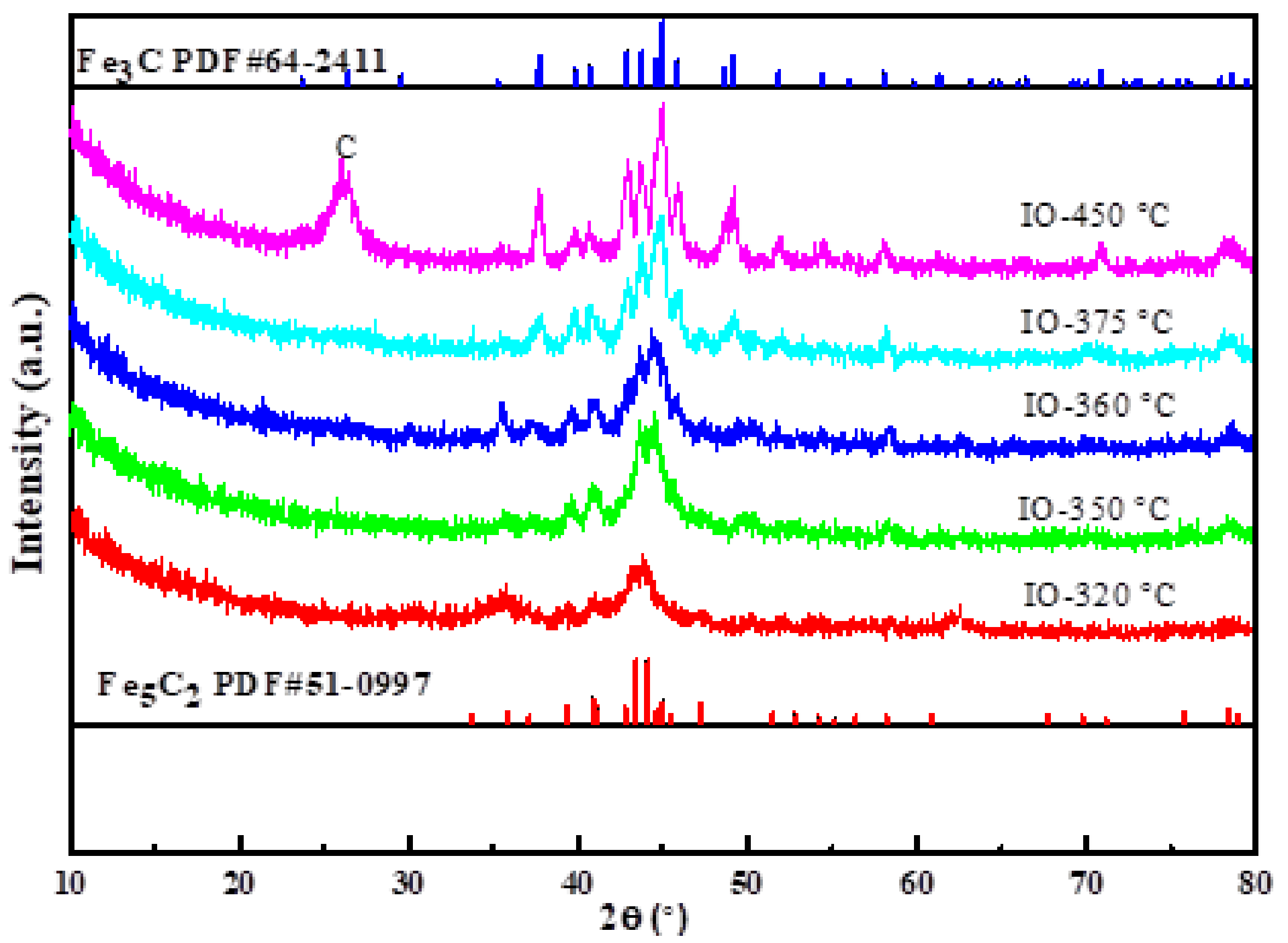
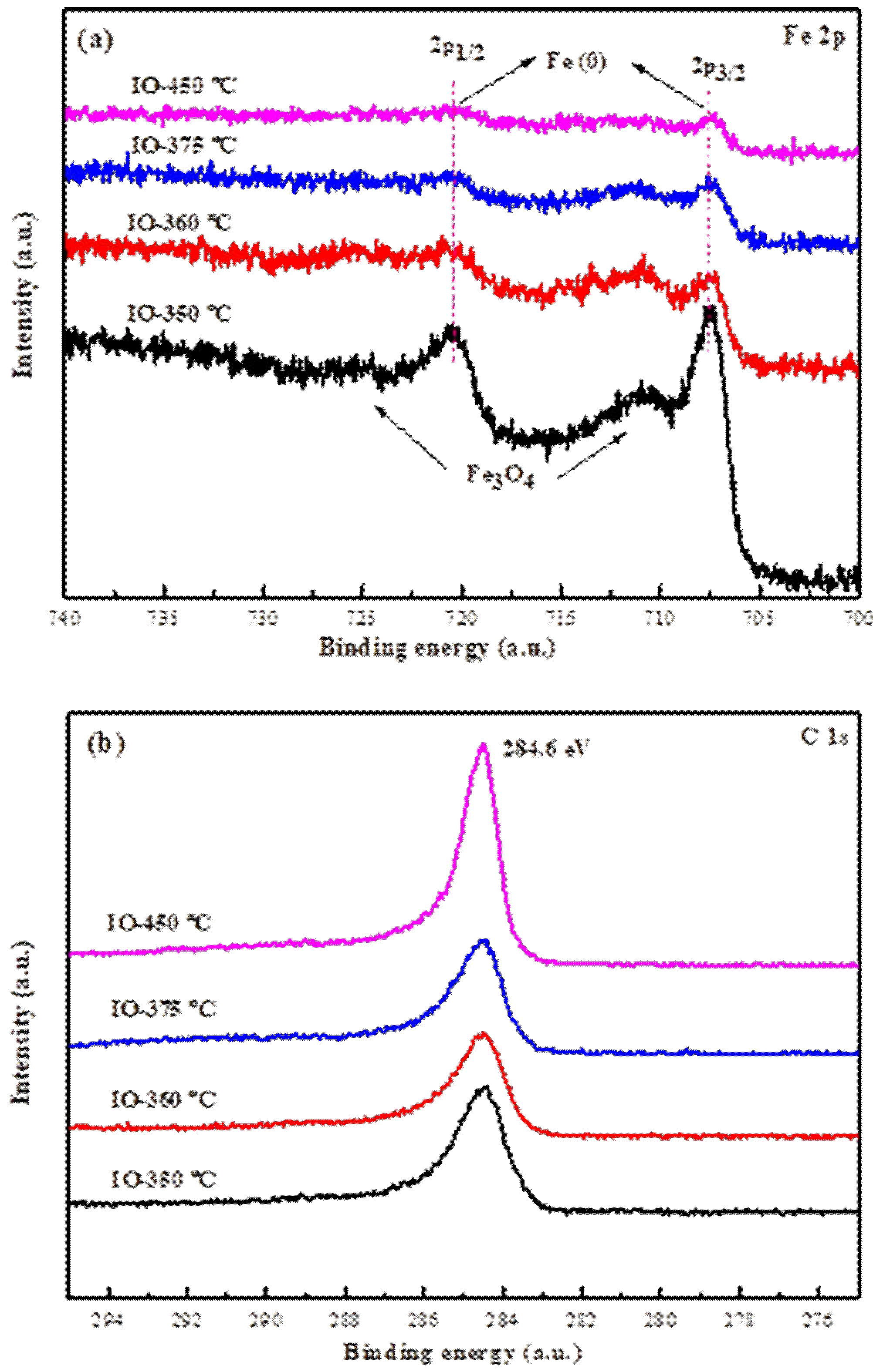
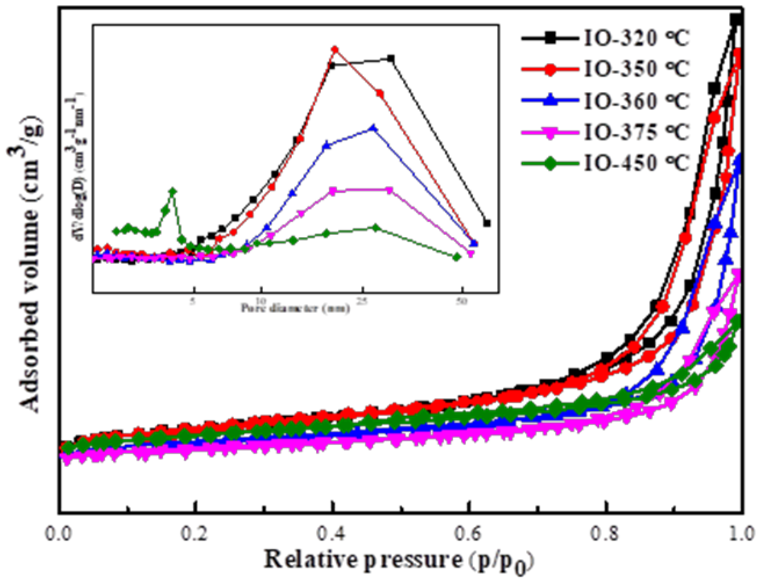
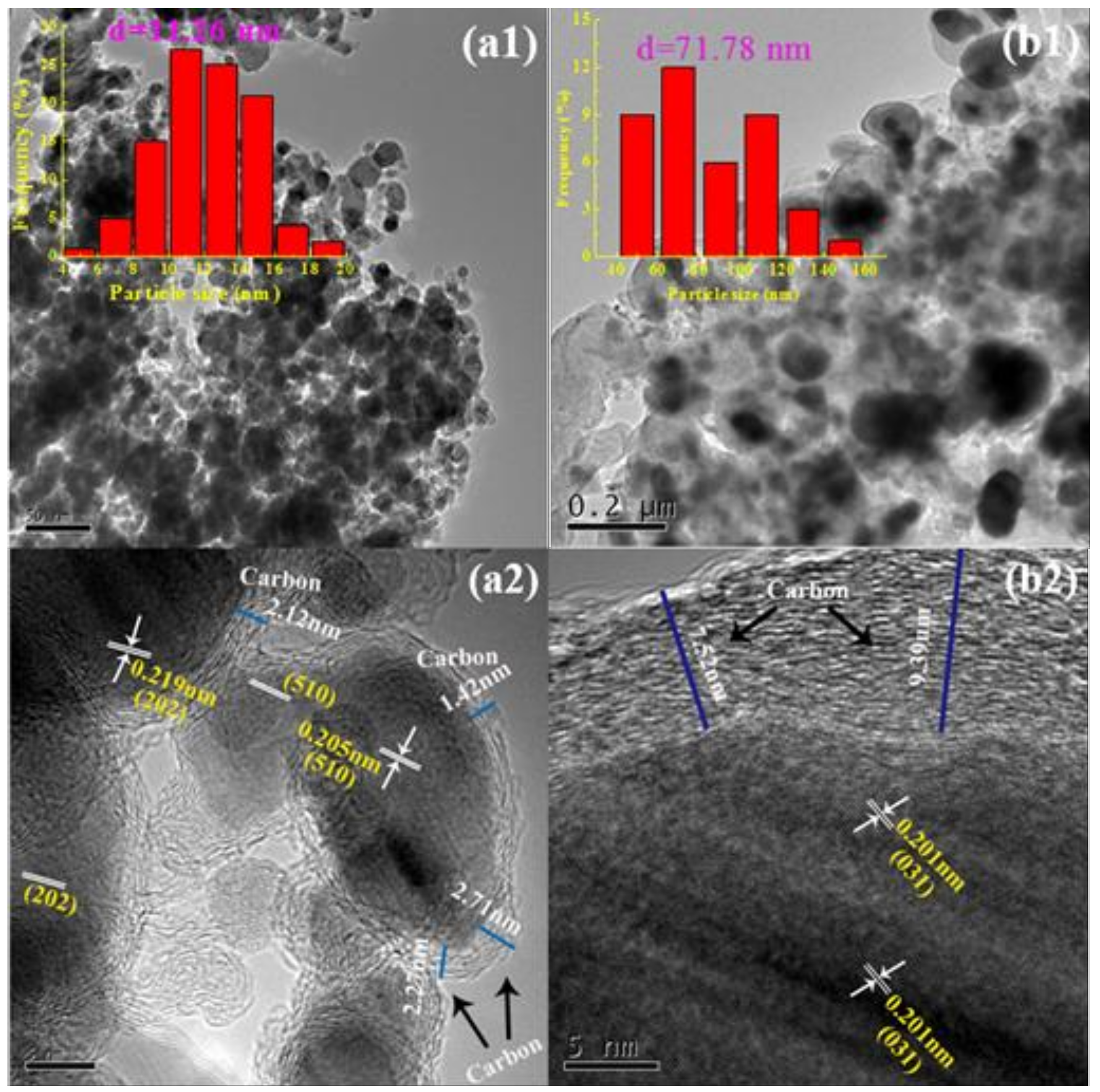
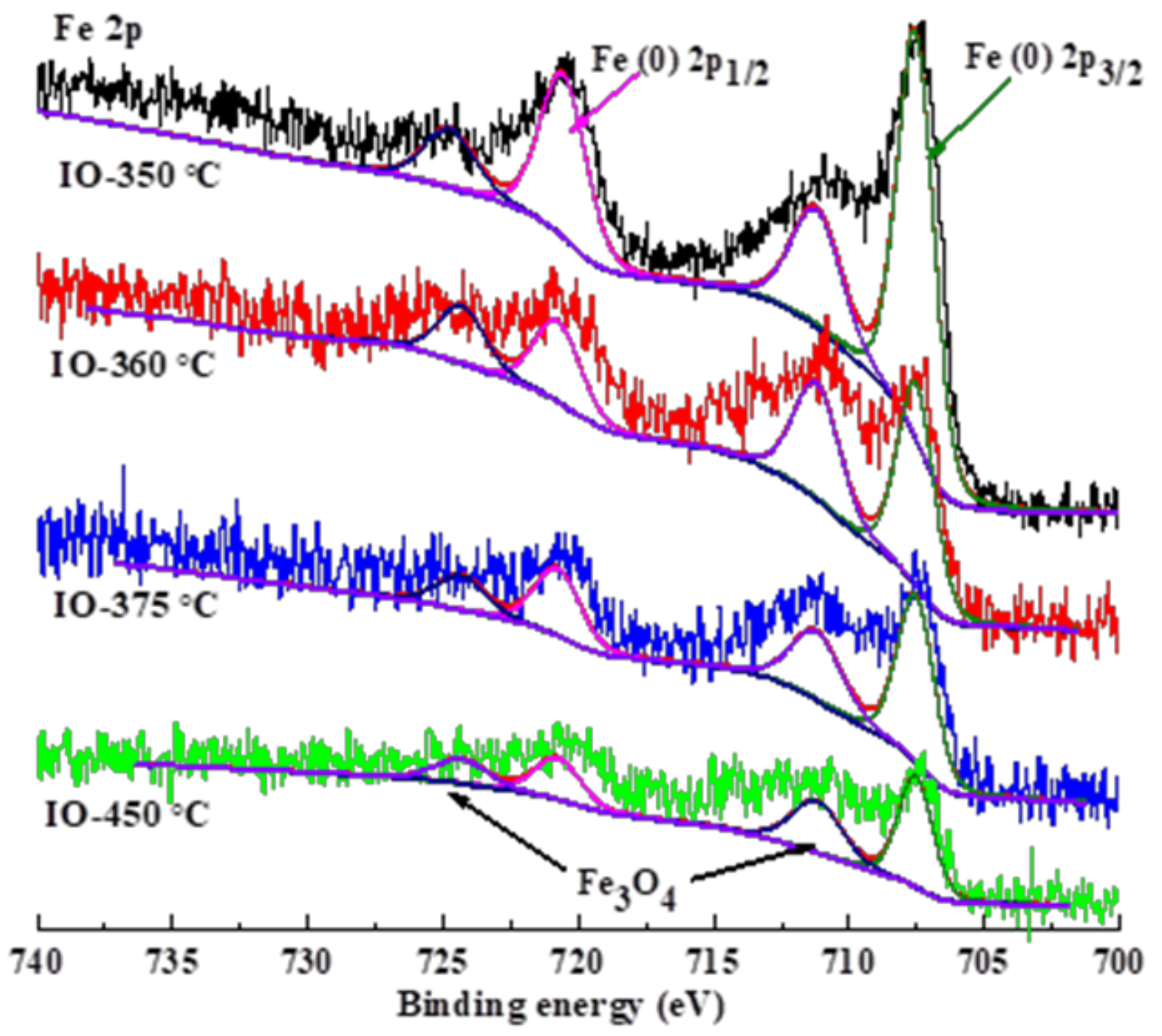
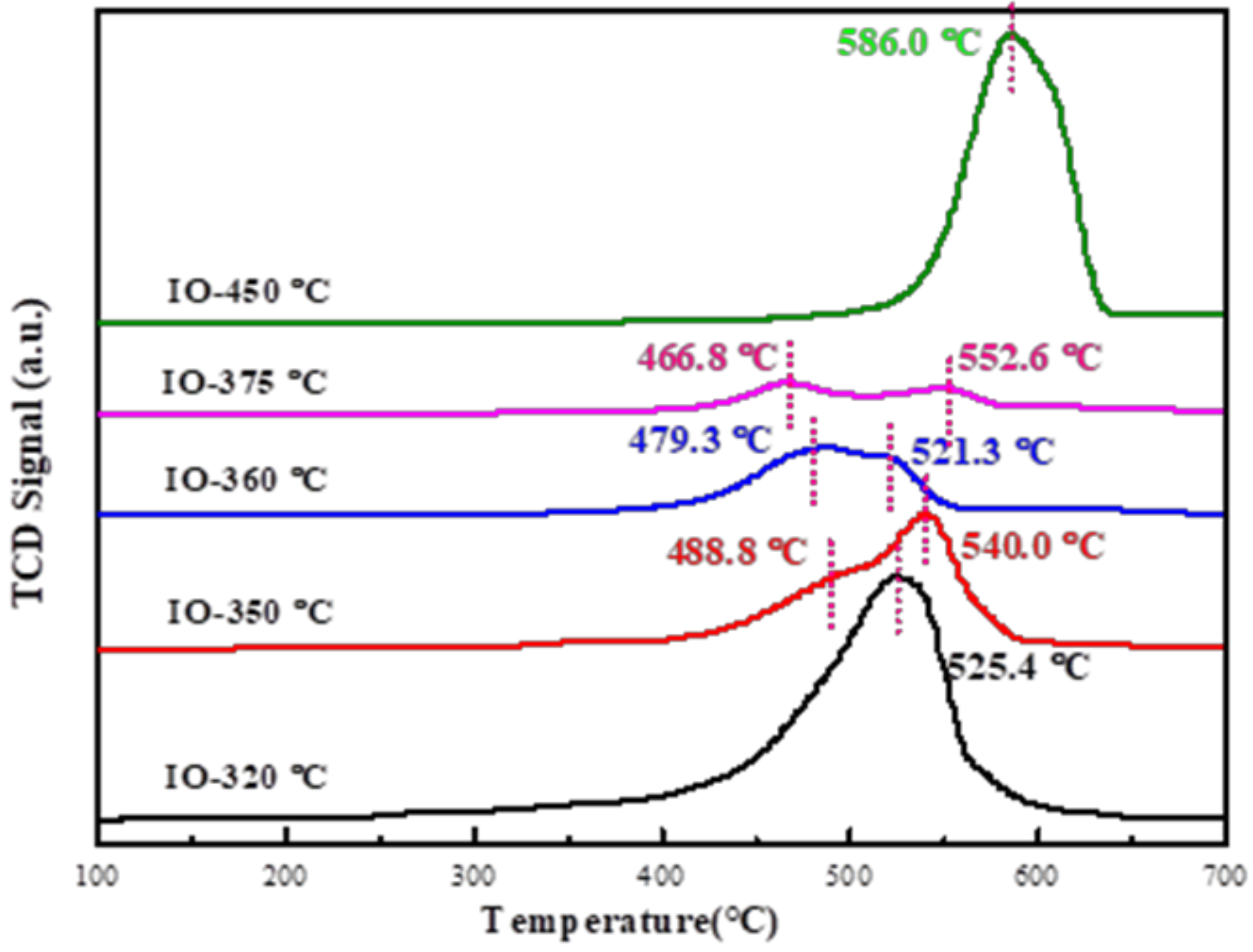
2.1. Characterization Catalysts

Characterization of the As-Prepared Iron Carbides

The crystal phase of the prepared iron carbide catalysts by carburization of iron oxalate at different temperatures was investigated using the X-ray diffraction (XRD) patterns as shown in Figure 1. The IO-320 °C catalyst displayed diffraction peaks at 39.31°, 40.83°, 43.40°, 44.08°, and 47.18°, which were assigned to Fe5C2 phase (JCPDS, NO. 51-0997). The patterns indicated that pure Fe5C2 began to form when the temperature rose to 320 °C under CO flow. Furthermore, the main peak intensity of the IO-350 °C catalyst was stronger than the IO-320 °C one, and the peak position slightly shifted to a high angle, suggesting that the IO-350 °C catalyst was not only single-phase Fe5C2, but also had a small amount of Fe3C [21]. The following CO temperature-programmed desorption (CO-TPD) can be used as a basis for the existence of two iron carbide phases. When the carburization temperature continued to increase to 375 °C, the catalyst displayed diffraction peaks at 37.76°, 39.82°, 40.65°, 42.89°, 43.76°, 45.00°, 45.88° and 49.13°, which were attributed to Fe3C (JCPDS, NO. 64-2411). Similarly, a small amount of Fe5C2 was still observed. With the carburization temperature rising to 450 °C, the peak of Fe3C became sharper and its intensity increased, suggesting that the fraction of Fe3C carbide increased or was gradually dominated by the Fe3C phase. In addition, the carbon peak was detected at 450 °C, which was attributed to the decomposition of the carbon-containing precursors which was more intense in the CO atmosphere and at relatively high temperatures. Interestingly, the two iron carbide phases (Fe3C and Fe5C2) co-existed at 360 °C, which was considered to be the transition temperature for the phase transition observed in XRD, because the peaks at 43.40°, 44.08°, 42.89°, 43.76°, 45.00° and 45.88° are assigned to the characteristic peaks of both carbides.
The X-ray photoelectron spectroscopy (XPS) spectrum (Figure 2) was employed to confirm the surface nature of the IO-t °C catalysts. In the spectrum (Figure 2a), the binding energies of Fe 2p1/2 (720.5 eV) and Fe 2p3/2 (707.5 eV) of IO-t °C catalysts were assigned to the iron carbide (Fe (0)) species [12,23,24]. Furthermore, one set of assigned weak peaks at ~710 and ~724 eV can be classified as Fe3O4, indicating that the co-existence of the iron carbide phases and magnetite phase at the catalyst surface (the specific peak splitting is shown in Figure 3). It is worthwhile to note that the intensity of peaks related to the iron species decreased with the increasing carburization temperature. Moreover, the C 1s spectrum strength at ~284.6 eV (Figure 2b) increased. The reason can be attributed to the carbon shells on the outer surface of the iron carbide nanoparticles, which made it difficult to detect the iron species peaks in the Fe 2p spectrum. Consequently, it is concluded that the catalysts are mainly composed of iron carbide components and an outer amorphous carbon decoration.
The physical and texture properties of the prepared catalysts as measured by N2 physisorption are shown in Figure 4 and Table 1. The N2 adsorption-desorption isotherms at −196 °C for the iron carbide catalysts carburized at different temperatures exhibited type IV isotherms, indicating that these catalysts were mesoporous materials [25]. When the carburization temperature rose from 320 to 450 °C, the adsorption amount of N2 on the catalyst and the hysteresis loops surface decreased. According to the pore diameter distribution plot, the pore size of the IO-350 °C catalyst was about 15–25 nm. With the increase in the carburization temperature, the window of the most suitable pore diameter became wider and the pore volume decreased gradually, which indicated that the mesoporous materials were gradually transformed into pore-free materials. We think that one of the reasons for the pore volume and the pore size decrease consistently was the phases changed with the increase in carburization temperature, and the other was the influence of surface carbon [25]. When the carburization temperature rose to 450 °C, a small number of pores of 2−4 nm appeared; that is, the catalyst presented a multilevel pore distribution. Here it is inferred that the pore of 2−4 nm was related to the formation of surface carbon. The study of surface carbon will be the focus of our future research.
The Brunner-Emmet-Taller (BET) surface areas and total pore volume of the catalysts at different carburization temperatures decreased significantly from 95.08 m2∙g−1, 0.39 m3∙g−1 for the IO-350 °C catalyst to 50.02 m2∙g−1, 0.18 m3∙g−1 for the IO-375 °C catalyst, respectively. However, the BET surface area of the IO-450 °C catalyst slightly increased to 76.12 m2∙g−1, which was related to the multilevel pore distribution caused by the surface carbon of the iron carbide at this temperature. Another explanation for this phenomenon was that the carbon deposition caused by the carburization process, blocking the pore channels of the catalyst, and then reducing the specific surface area of the catalyst [26]. When the carbon deposit reached a certain level, however, the increase of the carbon deposition area was more than the decrease of the specific surface area caused by the pore blockage, resulting in the increase in the specific surface area [26]. The phase structure and particle size distribution (PSD) of the fresh catalysts were characterized by high resolution-transmission electron microscopic (HR-TEM), as shown in Figure 5. Figure 5(a1) shows the uniform distribution of small Fe5C2 nanoparticles and the average particle size of the IO-350 °C catalyst was about 11.26 nm, which was estimated by randomly selecting about 100 particles. Additionally, for the IO-450 °C catalyst (Figure 5(b1)), the Fe3C particles were obviously enlarged, slightly agglomerated, and the surface was unclear, indicating that the surface was covered by a thick carbon layer. Meanwhile, the PSD was 71.78 nm for the IO-450 °C catalyst, which was obviously larger than that of the IO-350 °C catalyst. This indicates no regularity to the catalytic performance. Therefore, the particle size difference of iron species observed here is believed not to be a key factor for the distinguished promotion effect in the catalytic activity and selectivity. These results indicate that the pore structure and particle size have no significant effect on the catalytic performance of CO hydrogenation.
To further investigated the microstructures of the catalysts, the transmission electron microscopic (TEM) analysis was carried out. Figure 5(a2) shows the high resolution-transmission electron microscopic (HR-TEM) image of the IO-350 °C catalyst. The well-crystallized structures with lattice fringes of about 0.205 and 0.219 nm, which matched well to the value of the Fe5C2 (510) and (202) crystal phase [12,23], respectively, are confirmed. The Fe3C nanoparticle within IO-450 °C catalyst (Figure 5(b2)) was a single crystal with a lattice distance of 0.201 nm, corresponding to an interplanar spacing of the Fe3C (031) crystal plane. In addition, it was confirmed that the Fe5C2/Fe3C nanoparticles were encapsulated by a carbon shell from the high resolution-transmission electron microscopic (HR-TEM) image [23,27]. It can also be seen that the carbon layer thickness of the IO-350 °C catalyst was about 2 nm, while the carbon layer thickness of the IO-450 °C catalyst was 7 to 10 nm. Therefore, the increase of the carburization temperature could not only change the carbide phases, but also make the carbon layer thicker.

2.2. Fischer–Tropsch Synthesis (FTS) Performance

To explore the influence of the carburization temperature of iron oxalate on the catalytic performance, Table 2 summarized the catalytic activities and hydrocarbon distribution of the IO-t °C catalysts under the reaction conditions at 320 °C, 1 MPa, H2/CO = 1.5, GHSV = 6000 h−1. As presented in Table 2, the CO conversion started at 96% (IO-320 °C catalyst) and only decreased with the increase in the carburization temperature, until approaching a relatively constant value of about 48% (IO-375 °C and IO-450 °C catalysts). Compared with other catalysts, the IO-360 °C catalyst had a relatively higher light olefins selectivity and O/P value. With the further increase of the carburization temperature, the light olefins selectivity of the IO-375 °C and IO-450 °C catalysts decreased even if it is the same as the Fe3C phase, while more C5+ was formed, especially obvious for IO-450 °C catalyst. In addition, the CO2 selectivity decreased with the increase in the carburization temperature. In other words, the Fe3C phase had a lower water gas shift (WGS) activity.

3. Discussion

3.1. Effect of Surface Adsorption Properties on FTS Performance

CO-TPD was used to infer the ability of the catalyst to adsorb CO, which can reflect the change of the activity and products in FTS. Figure 6 shows the CO temperature-programmed desorption (CO-TPD) profiles of the iron carbide catalysts at different carburization temperatures. According to the results, a series of broadening CO desorption peaks were observed at high temperature (400–650 °C), which indicated that a certain amount of carbonated gas atoms (C,O or H et al.) were dissociated and adsorbed in the iron carbide bulk phase [26]. Observing the peaks position, the location of the desorption peak was almost unchanged with the increase of the carburization temperature, but the intensity decreased obviously. Specifically, there were two desorption peaks for the IO-350 °C, IO-360 °C and IO-375 °C catalysts, respectively, which meant that two active sites existed at the same time. The reason for inhibiting CO adsorption is that the crystal form of Fe3C was not completely formed; thus, the interaction force between CO was weaker. On the other hand, the carbon deposition significantly affected the surface adsorption [28]. The changing trend of the CO desorption peak intensity and area was consistent with the change of the activity in the reaction process. However, the peak intensity and area increased sharply for the IO-450 °C catalyst at 586.0 °C, which indicated that the binding force between Fe3C and CO was enhanced. The internal micropores (pore diameter 2–4 nm) made it desorption difficult after CO adsorption, and the peak moved towards higher temperature. These were the reasons for the lower activity of the IO-450 °C catalyst and the increased selectivity of the long-chain hydrocarbons (C5+). It has been reported that the desorption peak at about 75 °C corresponds to the linear desorption of CO on the catalyst surface, and peaks between 150 and 400 °C belong to the surface dissociation of CO from the catalyst [29]. It can be seen that no linear adsorption of iron carbide was observed in this paper.

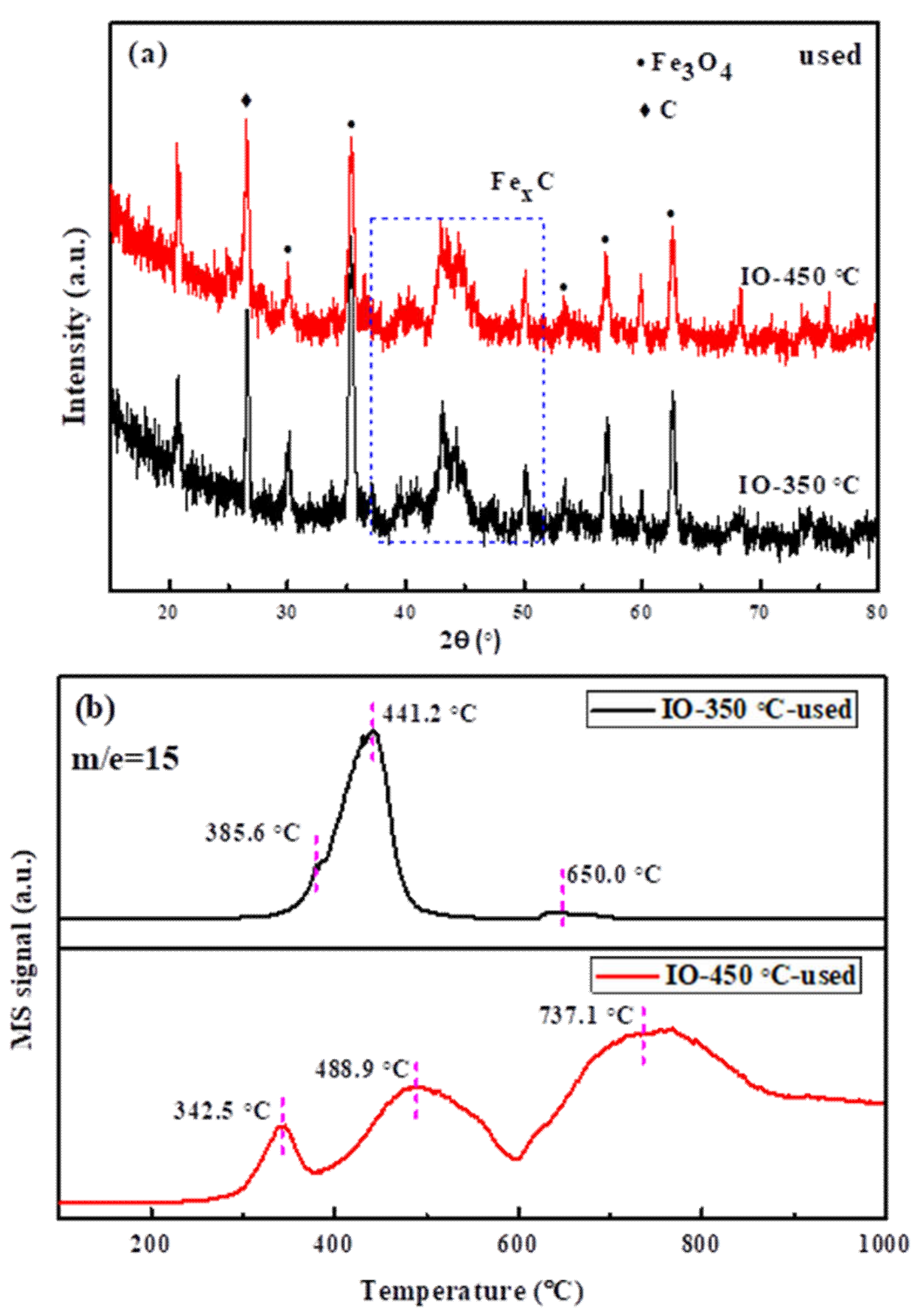
3.2. Characterization of the Used Iron Carbide Catalysts

It is a challenge to make sure the phase of iron carbide before and after the FTS reaction is consistent, and the phases of the used IO-350 °C and IO-450 °C catalysts were characterized by XRD (Figure 7a). It can be seen that in addition to the respective iron carbide (Fe5C2 and Fe3C) phases, the used catalysts also have a Fe3O4 phase, that is, internal oxidation occurred [30,31], which is the active phase of the WGS reaction. It can be said that the iron carbide phases of the used catalyst have been maintained almost the same as the fresh catalysts.
In order to determine what kinds of carbon species existed in the used catalysts, the temperature-programmed hydrogenation (TPH) characterization was performed, as shown in Figure 7b. Hydrogen reacts with various forms of carbon over the catalyst and evolved methane. Three peaks were observed in the used IO-350 °C and IO-450 °C catalysts based on their reactivity towards H2, indicating three types of carbonaceous species [29,32]. For the used IO-450 °C catalyst, the first species at 320 °C corresponded to atomic carbon or surface carbide, the middle region between 500 and 600 °C was considered to be Fe3C carbide [32], and, finally, the one at the temperature above 600 °C was classified as graphitic carbons. The used IO-350 °C catalyst had amorphous carbon at 400 °C and only a small amount of graphitic carbons at 620 °C. The second species (~450 °C) belonged to the Fe5C2 carbide. Xu et al. [29] divided different carbons formed on the iron catalysts surface into atomic or amorphous or bulk carbides or disordered or ordered graphitic carbon based on the temperatures. Those hydrogenating in the temperature range from 440 to 600 °C were classified as iron carbides. The results further indicate that iron carbides are present in all the used catalysts, and there are amorphous carbons and graphite carbons as well.

3.3. Effect of Carburization Temperature on FTS Activity and Selectivity

From the evaluation data of Section 2.2, the IO-320 °C catalyst exhibited the highest activity compared to the others, owing to the fact of the appearance of pure Fe5C2 phase at the present carburization temperature according to the XRD patterns. Here the specific surface area was larger and the grain size was smaller, which was also the reason for the high CO conversion [33]. However, the CO conversion over IO-350 °C catalyst decreased slightly because of the increase of grain size and the change of phase. Compared with other catalysts, the IO-360 °C catalyst had a higher light alkene to alkane ratio, light olefins selectivity and better CO conversion performance, which was related to the co-existence of the two iron carbide phases and generation of synergistic effects. The performance of the IO-375 °C and IO-450 °C catalysts can be analyzed in two aspects. On the one hand, combining with CO-TPD and XRD characterization, it was difficult to desorb CO on the catalyst surface when Fe3C was in its dominate phase. On the other hand, the confinement effect of the carbon layer was provided by specific chemical surroundings of the thicker carbon layers [34]. Therefore, the dual effects of the phase transition and carbon confinement effect were the reasons for the increase in the long-chain hydrocarbons selectivity. This trend of activity change suggested that the Fe5C2 phase guaranteed the higher activity, and the activity of Fe3C was generally low, which was consistent with previous reports [35,36]. For the product’s selectivity, the C2-C4 light olefins selectivity was relatively high when Fe5C2 and Fe3C co-existed and only a small amount of Fe3C existed (IO-360 °C catalysts). The products were mostly long-chain hydrocarbons when the Fe3C phase was dominant. It is well known that CO conversion has an effect on the product distribution. Generally speaking, CO conversion was opposite to olefin selectivity. However, in this paper, when the conversion was low, the selectivity of light olefins was also low.

4. Materials and Methods

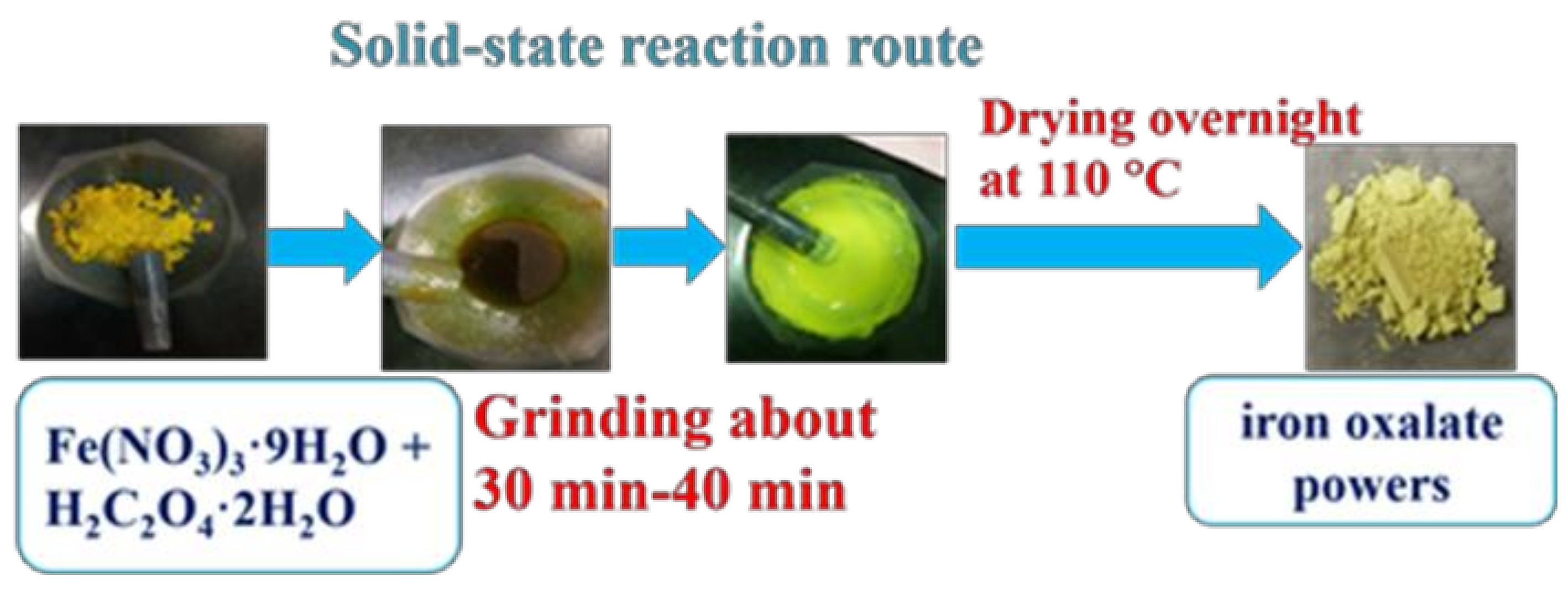
4.1. Catalyst Preparation

The iron oxalate precursor was prepared by solid-state reaction at room temperature [37], and the flow-process diagram of preparation was as shown in Figure 8. Fe(NO3)3·9H2O and H2C2O4·2H2O were used as raw materials. After accurately being weighed with a molar ratio of 2/3, the materials were crushed into powders in an agate mortar in advance, respectively. Then the two fine powders were well mixed and ground for 30–40 min until the solution was yellowish and sticky. During the milling, pungent gases were emitted. Subsequently, the homogeneous mixture was transferred into a beaker and then dried at 110 °C overnight. Finally, the collected product was iron oxalate powders.
The powders were crushed and sized to 60–100 mesh (0.15–0.30 μm), then the moulded particles were transferred to a quartz boat in a tube-type furnace with a ramping rate of 5 °C min−1, and activated under a CO flow of 80 ml·min−1 at different temperatures (320–450 °C). The samples were then thermally treated at the same temperature for 4 h under a continuous flow of CO. Finally, the samples were taken from the tube furnace after cooling to room temperature. The samples were marked as IO-t °C (IO represents iron oxalate precursor, and t represents carburization temperature).

4.2. Characterization

The structures of the catalysts were determined by X-ray diffraction (XRD) (Rigaku, Thermo ARL SCINTAGX TRA, Écublens, Switzerland) equipped with Cu Kα radiation (λ = 1.54050 Å, 40 kV, 40 mA) at a step size of 0.02° and a scanning rate of 5°·min−1 between 10 and 80°. The crystallite phases were identified by comparing the diffraction patterns with the data of the Joint Committee on Powder Diffraction Standards (JCPDS).
N2 adsorption-desorption isotherms at −196 °C were obtained with a Micromeritics ASAP2010 (GA, USA) gas adsorption analyzer. Prior to the analysis, the samples were degassed at 200 °C for 6 h. The total surface area was calculated by the Brunauer-Emmett-Teller (BET) equation, and the total pore volume and average pore size were determined by the Barrett-Joyner-Hallenda (BJH) method.
The CO-TPD experiments were performed using a micro fixed-bed reactor connecting with a thermal conducted detector (TCD). About 50 mg of catalysts were loaded in the reactor and were heated in He (50 mL·min−1) from room temperature to 300 °C for removing the surface impurities. The samples were subsequently cooled to 100 °C under the flow of He and then exposed to CO for 2 h, followed by purging with He for 30 min to remove the weekly adsorbed species and decreasing it to room temperature until a stable baseline was obtained. After this step, temperature-programmed desorption (TPD) was performed from room temperature to 700 °C with a ramping rate of 10 °C·min−1.
Transmission electron microscopy (TEM) images were taken by using a Tecnai G2 F30 S-Twin instrument (FEI Company, OR, USA) with an acceleration voltage of 300 kV. The samples for TEM analysis were prepared by ultrasonically dispersing the power sample in ethanol, drops of the suspension were deposited on a carbon-coated copper grid and dried under ambient conditions.
The chemical states and contents of elements on the near surface of the sample were detected by X-ray photoelectron spectroscopy (XPS, Thermo Scientific Escalab 250 Xi, Basel, Switzerland) using Al Kα as the excitation source, where the parameters were set to a 15 kV working voltage, 250 W capacity factor and 0.05 eV per step. The original data was fitted with the XPS Peak software.
The temperature programmed hydrogenation (TPH) was carried out using a Micromeritics Autochem 2910 instrument (GA, USA) coupled with a gas analyzer system/mass spectrometer (MS). About 50 mg of the used catalysts were placed in a U type quartz tube and heated from room temperature to 110 °C with a ramping rate of 10 °C·min−1 under He flow at 20 mL·min−1 for 1 h. After that, the sample was heated in pure H2 at the same heating rate and flow rate from 110 to 1000 °C at atmospheric pressure. The evolution of methane (m/e = 15, instead of 16 to avoid interference from ionized oxygen coming from steam) was monitored.

4.3. Fischer–Tropsch Synthesis

The FTS reaction was carried out on a fixed-bed flow reactor (stainless steel, inner diameter = 13 mm) with a gas mixture containing 40% CO and 60% H2 at 320 °C. Typically, 0.5 mL if catalyst (60–100 mesh) was diluted with 5.5 mL of quartz sand (60–100 mesh) and then loaded in a stainless-steel tube. For all the catalysts studied in this paper, no H2 or CO activation was adapted in advance. The gas hourly space velocity (GHSV) of the reaction was set at 6000 h−1 (6000 ml·h−1·mLcat−1). The temperature was ramped from 30 to 320 °C at 3 °C ·min−1 and we kept the pressure at 1.0 MPa.
The feed gas and outlet gases were measured online by using a gas chromatograph (Shimadzu GC-2014, Kyoto, Japan) equipped with double columns and double detectors. The CO, CH4, and CO2 were detected using a carbon molecular sieves column (TDX-01) with a thermal conductivity detector (TCD); C1-C5 ranged hydrocarbon products were analyzed using an alumina capillary column with a flame ionization detector (FID). The aqueous products, wax oil products and liquid products were collected in a 160 °C hot trap and a 0 °C cooling trap during the reaction, respectively. Furthermore, the product selectivity was calculated based on the carbon mass balance.

5. Conclusions

In summary, we have demonstrated a facile and efficient solid-state reaction-carburization method for preparing the iron carbide catalysts with different phases (Fe5C2 or Fe3C catalysts), and these iron carbides were applied to FTS without in situ activation treatment. The effects of carburization temperature on the phase structure and surface properties of the catalyst were investigated, meanwhile, the activity and the products distribution were closely related to the types of iron carbides. The temperature of 360 °C was the transition temperature at which the iron carbide phase transformed from the Fe5C2 phase to the Fe3C phase. The IO-360 °C catalyst showed a relatively higher light olefins selectivity and weaker hydrogenation ability in the lower hydrocarbon range. All in all, Fe5C2 gives an assurance of higher CO conversion; two components (Fe5C2 and Fe3C phases) co-existed and a quantity of Fe3C existed by self-combination, which are the assurance of higher light olefins selectivity. On the basis of the IO-360 °C catalyst with a higher light olefins selectivity, the carburization heating process and carburization atmosphere will be improved to further improve the selectivity of light olefins. At the same time, the synergistic effect between the surface carbon thickness and carbides will also influence the performance of the catalyst. The study of surface carbon will be the focus of our future research.

Author Contributions

Catalyst synthesis, testing, data analysis and manuscript drafting was done by H.Z., while X.Y. provided experimental considerations, characterization and wrote the paper. Y.L. was in charge of checking the grammatical sentences of the manuscript, and C.H. supervised the entire work and proofread the document.

Funding

This research was funded by Zhejiang Natural Science Foundation (grant number LY18B060015), Zhejiang province education department scientific research projects (grant number Y201326527) and Zhejiang Natural Science Foundation (grant number LQ19B06007).

Acknowledgments

We thank the Analytical and Testing Center of Zhejiang University of Technology for their assistance in transmission electron microscopic and X-ray photoelectron spectroscopy characterizations. This work is supported by members of the Institute of Industrial Catalysis.

Conflicts of Interest

The authors declare no conflict of interest.

References

  1. Casavola, M.; Hermannsdorfer, J.; de Jonge, N.; Dugulan, A.I.; de Jong, K.P. Fabrication of Fischer-ropsch Catalysts by Deposition of Iron Nanocrystals on Carbon Nanotubes. Adv. Funct. Mater. 2015, 25, 5309–5319. [Google Scholar] [CrossRef]
  2. Jiao, F.; Li, J.; Pan, X.; Xiao, J.; Li, H.; Ma, H.; Wei, M.; Pan, Y.; Zhou, Z.; Li, M.; et al. Selective conversion of syngas to light olefins. Science 2016, 351, 1065–1068. [Google Scholar] [CrossRef] [PubMed]
  3. Galvis, H.M.T.; de Jong, K.P. Catalysts for Production of Lower Olefins from Synthesis Gas: A Review. ACS Catal. 2013, 3, 2130–2149. [Google Scholar] [CrossRef]
  4. Galvis, H.M.T.; Koeken, A.C.J.; Bitter, J.H.; Davidian, T.; Ruitenbeek, M.; Dugulan, A.I.; de Jong, K.P. Effect of precursor on the catalytic performance of supported iron catalysts for the Fischer–Tropsch synthesis of lower olefins. Catal. Today 2013, 215, 95–102. [Google Scholar] [CrossRef]
  5. Lu, Y.; Yan, Q.; Han, J.; Cao, B.; Street, J.; Yu, F. Fischer-Tropsch synthesis of olefin-rich liquid hydrocarbons from biomass-derived syngas over carbon-encapsulated iron carbide/iron nanoparticles catalyst. Fuel 2017, 193, 369–384. [Google Scholar] [CrossRef]
  6. Sun, B.; Xu, K.; Nguyen, L.; Qiao, M.; Tao, F. Preparation and Catalysis of Carbon-Supported Iron Catalysts for Fischer-Tropsch Synthesis. ChemCatChem 2012, 4, 1498–1511. [Google Scholar] [CrossRef]
  7. Liu, K.; Suo, H.; Zhang, C.; Xu, J.; Yang, Y.; Xiang, H.-W.; Li, Y.-W. An active Fischer-Tropsch synthesis FeMo/SiO2 catalyst prepared by a modified sol-gel technique. Catal. Commun. 2010, 12, 137–141. [Google Scholar] [CrossRef]
  8. Galvis, H.M.T.; Koeken, A.C.J.; Bitter, J.H.; Davidian, T.; Ruitenbeek, M.; Dugulan, A.I.; de Jong, K.P. Effects of sodium and sulfur on catalytic performance of supported iron catalysts for the Fischer–Tropsch synthesis of lower olefins. J. Catal. 2013, 303, 22–30. [Google Scholar] [CrossRef]
  9. Zhai, P.; Xu, C.; Gao, R.; Liu, X.; Li, M.; Li, W.; Fu, X.; Jia, C.; Xie, J.; Zhao, M.; et al. Highly Tunable Selectivity for Syngas-Derived Alkenes over Zinc and Sodium-Modulated Fe5C2 Catalyst. Angew. Chem. Int. Ed. Engl. 2016, 55, 9902–9907. [Google Scholar] [CrossRef]
  10. Yu, G.; Sun, B.; Pei, Y.; Xie, S.; Yan, S.; Qiao, M.; Fan, K.; Zhang, X.; Zong, B. FexOy@C Spheres as an Excellent Catalyst for Fischer-Tropsch Synthesis. J. Am. Chem. Soc. 2010, 132, 935–937. [Google Scholar] [CrossRef]
  11. An, B.; Cheng, K.; Wang, C.; Wang, Y.; Lin, W. Pyrolysis of Metal-Organic Frameworks to Fe3O4@Fe5C2 Core-Shell Nanoparticles for Fischer-Tropsch Synthesis. ACS Catal. 2016, 6, 3610–3618. [Google Scholar] [CrossRef]
  12. Yang, C.; Zhao, H.; Hou, Y.; Ma, D. Fe5C2 Nanoparticles: A Facile Bromide-Induced Synthesis and as an Active Phase for Fischer-Tropsch Synthesis. J. Am. Chem. Soc. 2012, 134, 15814–15821. [Google Scholar] [CrossRef] [PubMed]
  13. Liu, Y.; Chen, J.-F.; Bao, J.; Zhang, Y. Manganese-Modified Fe3O4 Microsphere Catalyst with Effective Active Phase of Forming Light Olefins from Syngas. ACS Catal. 2015, 5, 3905–3909. [Google Scholar] [CrossRef]
  14. Wang, P.; Chen, W.; Chiang, F.-K.; Dugulan, A.I.; Song, Y.; Pestman, R.; Zhang, K.; Yao, J.; Feng, B.; Miao, P.; et al. Synthesis of stable and low-CO2 selective epsilon-iron carbide Fischer-Tropsch catalysts. Sci. Adv. 2018, 4, eaau2947. [Google Scholar] [CrossRef] [PubMed]
  15. Williams, B.; Clifford, D.; El-Gendy, A.; Carpenter, E.E. Solvothermal synthesis of Fe7C3 and Fe3C nanostructures with phase and morphology control. J. Appl. Phys. 2016, 120, 033904. [Google Scholar] [CrossRef]
  16. Mansker, L.D.; Jin, Y.; Bukur, D.B.; Datye, A.K. Characterization of slurry phase iron catalysts for Fischer-Tropsch synthesis. Appl. Catal. A 1999, 186, 277–296. [Google Scholar] [CrossRef]
  17. Datye, A.K.; Jin, Y.; Mansker, L.; Motjope, R.T.; Dlamini, T.H.; Coville, N.J. The nature of the active phase in iron Fischer-Tropsch catalysts. Stud. Surf. Sci. Catal. 2000, 130, 1139–1144. [Google Scholar]
  18. Chang, Q.; Zhang, C.; Liu, C.; Wei, Y.; Cheruvathur, A.V.; Dugulan, A.I.; Niemantsverdriet, J.W.; Liu, X.; He, Y.; Qing, M.; et al. Relationship between Iron Carbide Phases (ε-Fe2C, Fe7C3, and χ-Fe5C2) and Catalytic Performances of Fe/SiO2 Fischer–Tropsch Catalysts. ACS Catal. 2018, 8, 3304–3316. [Google Scholar] [CrossRef]
  19. Bukur, D.B.; Okabe, K.; Rosynek, M.P.; Li, C.P.; Wang, D.J.; Rao, K.; Huffman, G.P. Activation Studies with a Precipitated Iron Catalyst for Fischer-Tropsch Synthesis: I. Characterization Studies. J. Catal. 1995, 155, 353–365. [Google Scholar] [CrossRef]
  20. Gnanamani, M.K.; Hamdeh, H.; Jacobs, G.; Shafer, W.E.; Sparks, D.; Davis, B. Fischer-Tropsch synthesis: Activity and Selectivity of Fe5C2 and Fe3C carbides. In Fischer-Tropsch Synthesis, Catalysts, and Catalysis; Davis, B.H., Occelli, M.L., Eds.; CRC Press Taylor & Francis Group: Boca Raton, FL, USA, 2016; pp. 15–30. [Google Scholar]
  21. De Smit, E.; Cinquini, F.; Beale, A.M.; Safonova, O.V.; van Beek, W.; Sautet, P.; Weckhuysen, B.M. Stability and reactivity of ϵ-χ-θ iron carbide catalyst phases in Fischer-Tropsch synthesis: controlling μC. J. Am. Chem. Soc. 2010, 132, 14928–14941. [Google Scholar] [CrossRef]
  22. Zhang, Y.; Fu, D.; Liu, X.; Zhang, Z.; Zhang, C.; Shi, B.; Xu, J.; Han, Y.-F. Operando Spectroscopic Study of Dynamic Structure of Iron Oxide Catalysts during CO2 Hydrogenation. ChemCatChem 2018, 10, 1272–1276. [Google Scholar] [CrossRef]
  23. Hong, S.Y.; Chun, D.H.; Yang, J.-I.; Jung, H.; Lee, H.-T.; Hong, S.; Jang, S.; Lim, J.T.; Kim, C.S.; Park, J.C. A new synthesis of carbon encapsulated Fe5C2 nanoparticles for high-temperature Fischer-Tropsch synthesis. Nanoscale 2015, 7, 16616–16620. [Google Scholar] [CrossRef]
  24. Zhao, X.; Lv, S.; Wang, L.; Li, L.; Wang, G.; Zhang, Y.; Li, J. Comparison of preparation methods of iron-based catalysts for enhancing Fischer-Tropsch synthesis performance. Mol. Catal. 2018, 449, 99–105. [Google Scholar] [CrossRef]
  25. Liu, J.; Zhang, A.; Liu, M.; Hu, S.; Ding, F.; Song, C.; Guo, X. Fe-MOF-derived highly active catalysts for carbon dioxide hydrogenation to valuable hydrocarbons. J. CO2 Util. 2017, 21, 100–107. [Google Scholar] [CrossRef]
  26. Wang, R.; Wu, B.; Li, Y.-W. Synthesis of Single-Phase Iron Carbides and Their Adsorption Performance. Chinese J. Catal. 2012, 33, 863–869. [Google Scholar] [CrossRef]
  27. Wang, X.; Zhang, P.; Wang, W.; Lei, X.; Yang, H. Fe3C and Mn doped Fe3C nanoparticles: synthesis, morphology and magnetic properties. RSC Advances 2015, 5, 57828–57832. [Google Scholar] [CrossRef]
  28. Zhang, J.; Ma, L.; Fan, S.; Zhao, T.; Zhang, K. Effect of pretreatment of iron catalyst on light olefin selectivity in CO hydrogenation. J. Fuel Chem. Tech. 2012, 40, 1110–1114. [Google Scholar] [CrossRef]
  29. Xu, J.; Bartholomew, C.H. Temperature-programmed hydrogenation (TPH) and in situ Mossbauer spectroscopy studies of carbonaceous species on silica-supported iron Fischer-Tropsch catalysts. J. Phys. Chem. B 2005, 109, 2392–2403. [Google Scholar] [CrossRef] [PubMed]
  30. Peña, D.; Jensen, L.; Cognigni, A.; Myrstad, R.; Neumayer, T.; van Beek, W.; Ronning, M. The Effect of Copper Loading on Iron Carbide Formation and Surface Species in Iron-Based Fischer-Tropsch Synthesis Catalysts. ChemCatChem 2018, 10, 1300–1312. [Google Scholar] [CrossRef]
  31. De Smit, E.; Weckhuysen, B.M. The renaissance of iron-based Fischer-Tropsch synthesis: on the multifaceted catalyst deactivation behaviour. Chem. Soc. Rev. 2008, 37, 2758–2781. [Google Scholar] [CrossRef]
  32. Peña, D.; Cognigni, A.; Neumayer, T.; van Beek, W.; Jones, D.S.; Quijada, M.; Ronning, M. Identification of carbon species on iron-based catalysts during Fischer-Tropsch synthesis. Appl. Catal., A 2018, 554, 10–23. [Google Scholar] [CrossRef]
  33. Sun, Z.; Sun, B.; Qiao, M.; Wei, J.; Yue, Q.; Wang, C.; Deng, Y.; Kaliaguine, S.; Zhao, D. A General Chelate-Assisted Co-Assembly to Metallic Nanoparticles-Incorporated Ordered Mesoporous Carbon Catalysts for Fischer-Tropsch Synthesis. J. Am. Chem. Soc. 2012, 134, 17653–17660. [Google Scholar] [CrossRef]
  34. Zhu, C.; Zhang, M.; Huang, C.; Zhong, L.; Fang, K. Carbon-encapsulated highly dispersed FeMn nanoparticles for Fischer-Tropsch synthesis to light olefins. New J. Chem. 2018, 42, 2413–2421. [Google Scholar] [CrossRef]
  35. Wezendonk, T.A.; Santos, V.P.; Nasalevich, M.A.; Warringa, Q.S.E.; Dugulan, A.I.; Chojecki, A.; Koeken, A.C.J.; Ruitenbeek, M.; Meima, G.; Islam, H.-U.; et al. Elucidating the Nature of Fe Species during Pyrolysis of the Fe-BTC MOF into Highly Active and Stable Fischer-Tropsch Catalysts. ACS Catal. 2016, 6, 3236–3247. [Google Scholar] [CrossRef]
  36. Herranz, T.; Rojas, S.; Perez-Alonso, F.J.; Ojeda, M.; Terreros, P.; Fierro, J.L.G. Genesis of iron carbides and their role in the synthesis of hydrocarbons from synthesis gas. J. Catal. 2006, 243, 199–211. [Google Scholar] [CrossRef]
  37. Li, L.; Han, W.-F.; Li, L.-H.; Liu, H.Z. Modification of Wustite Based Ammonia Synthesis Catalyst With Fine Fe particles. J. Mol. Catal. 2017, 31, 206–214. [Google Scholar]
Figure 1. The X-ray diffraction (XRD) patterns of the iron carbide catalysts treated at different carburization temperature treatments.
Catalysts 09 00347 g001
Figure 2. XPS spectrum of the fresh IO-t °C catalysts: (a) Fe 2p, (b) C 1s.
Catalysts 09 00347 g002
Figure 3. The elaboration results of Fe 2p of the fresh IO-t °C catalysts.
Catalysts 09 00347 g003
Figure 4. The nitrogen adsorption-desorption isotherms and pore diameter distribution plot (inset) of the iron carbide catalysts at different carburization temperatures.
Catalysts 09 00347 g004
Figure 5. The transmission electron microscopic (TEM) images of the fresh IO-350 °C (a1,a2) and IO-450 °C (b1,b2) catalysts. The particle size distribution of each catalyst is inserted in (a1) and (b1).
Catalysts 09 00347 g005
Figure 6. The CO temperature-programmed desorption (CO-TPD) profiles of the iron carbide catalysts treated at different carburization temperatures.
Catalysts 09 00347 g006
Figure 7. (a): The X-ray diffraction (XRD) patterns of the used IO-350 °C, IO-450 °C catalysts; (b): The temperature-programmed hydrogenation (TPH) profiles of the used IO-350 °C, IO-450 °C catalysts for m/e = 15.
Catalysts 09 00347 g007
Figure 8. The flow-process diagram of preparation of iron oxalate powders precursor.
Catalysts 09 00347 g008
Table 1. The textural properties and crystallite size of iron carbide catalysts treated at different carburization temperatures.
SamplesSurface Area
(m2/g)
Pore Size
(nm)
Pore Volume
(cm3/g)
IO-320 °C92.7918.240.42
IO-350 °C95.0816.440.39
IO-360 °C64.6117.990.29
IO-375 °C50.0214.770.18
IO-450 °C76.127.380.14
Table 2. The Fischer-Tropsch Synthesis (FTS) properties of iron oxalate carbonized at different carburization temperatures a.
CatalystsX(CO)/%S(CO2)/%O/PbHydrocarbon Distribution/C mol%
CH4C2-C4 olefinsC2-C4 paraffinsC5+
IO-320 °C96.2326.371.3117.6521.3116.2444.80
IO-350 °C85.1824.351.5116.9621.3714.2147.46
IO-360 °C75.4624.401.5318.0922.8614.9644.09
IO-375 °C47.5923.541.0321.1520.5520.0238.27
IO-450 °C49.0120.951.0717.1716.4715.4650.91
a No pretreatment was performed before reaction. Catalysts were tested at 320 °C, 1 MPa, H2/CO (v/v) = 1.5, GHSV = 6000 h−1, b O/P represents the molar ratio of olefin to paraffin in the C2 to C4 range hydrocarbons.

