Article

The Reduction Temperature Effect of Fe–Co/MgO Catalyst on Characteristics of Multi-Walled Carbon Nanotubes

School of Electrical Engineering, Korea University, Seoul 136-713, Korea
*
Author to whom correspondence should be addressed.
Catalysts 2018, 8(9), 361; https://doi.org/10.3390/catal8090361
Submission received: 8 August 2018 / Revised: 22 August 2018 / Accepted: 25 August 2018 / Published: 28 August 2018

Abstract

:
Diameters and crystallinity of multi-walled carbon nanotubes (MWCNTs) dependent on reduction temperature of the Fe–Co/MgO catalyst were investigated. MWCNTs were synthesized by catalytic chemical vapor depositing and the Fe–Co/MgO catalyst was fabricated by using a sol-gel method. According to Raman analysis, transmission electron microscopy and thermogravimetric analysis, the diameter distribution of MWCNTs was broadened with increasing reduction temperature of the Fe–Co/MgO catalyst and crystallinity was improved. The above results are attributed to an increased size and enhanced crystallinity of metal catalyst particles by increasing reduction temperature.

1. Introduction

Carbon nanotubes (CNTs) have been studied as an important nanomaterial since its first discovery in 1991 [1]. Due to an excellent electrical conductivity and prominent mechanical properties, CNTs have been attracted a lot of attention in their potential applications such as field-effect transistors, field emission devices, electronic sensors, transparent electrodes, and composite materials [2,3,4,5,6,7]. For various applications of CNTs, the control of the growth and properties of CNTs is inevitably necessary because CNTs indicate quietly different electrical, mechanical, and material properties according to the diameter and crystallinity [8,9,10]. Therefore, it is still an interesting task to control the diameter and crystallinity of CNTs exactly during the growth of CNTs. Several methods have been developed for the synthesis of CNTs, such as arc-discharge, laser ablation methods, and catalytic chemical vapor deposition (CCVD) [11,12,13]. Among them, CCVD was considered to be typical and meaningful way to synthesis of CNTs with large scale, low coast, and mass production compared with the other methods [14,15,16]. There have been many reports for the catalyst effect on the growth and properties of CNTs using the CCVD method [17,18,19,20]. Most of the previous works mainly presented the growth of CNTs according to catalyst species, catalyst composition, and catalyst fabrication technique [15,21,22]. On the other hand, it is very difficult to find detailed study for properties of CNTs dependent on reduction temperature of the catalyst until now. Therefore, in this work, we deeply focused the reduction temperature effect of the catalyst on the growth of CNTs to understand a growth behavior of CNTs.

2. Results & Discussion

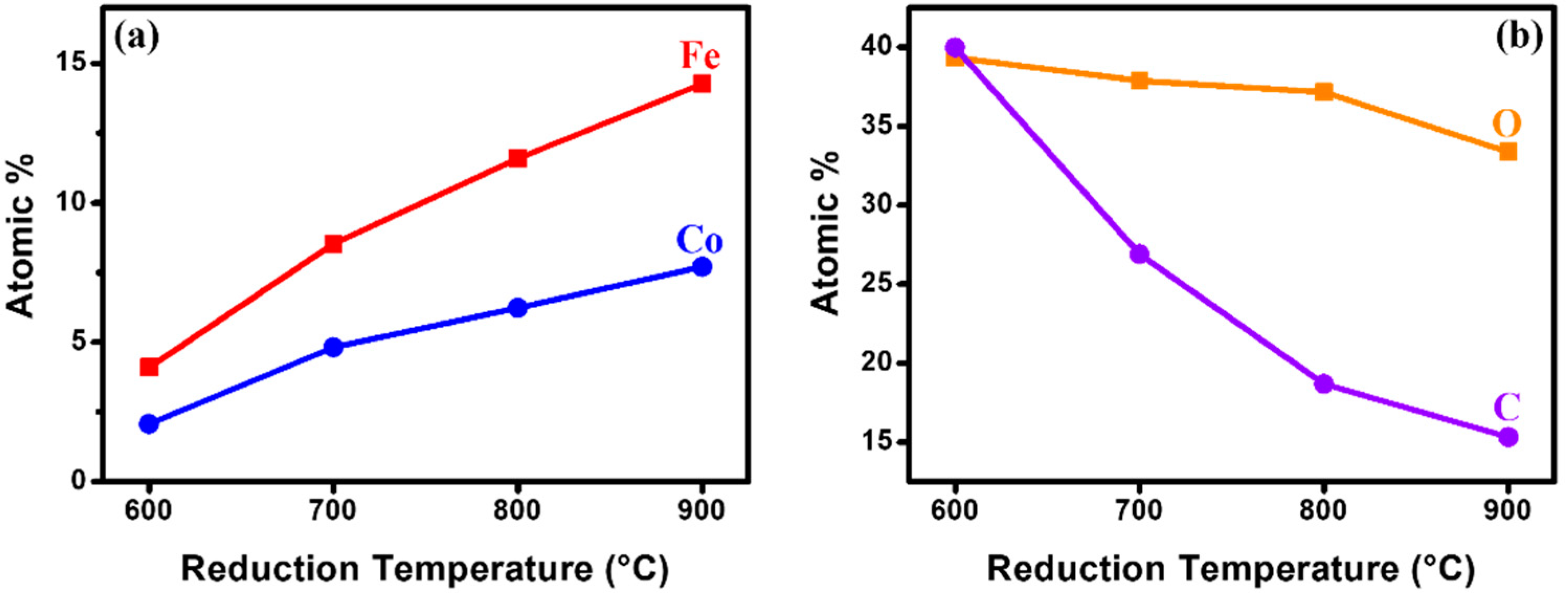
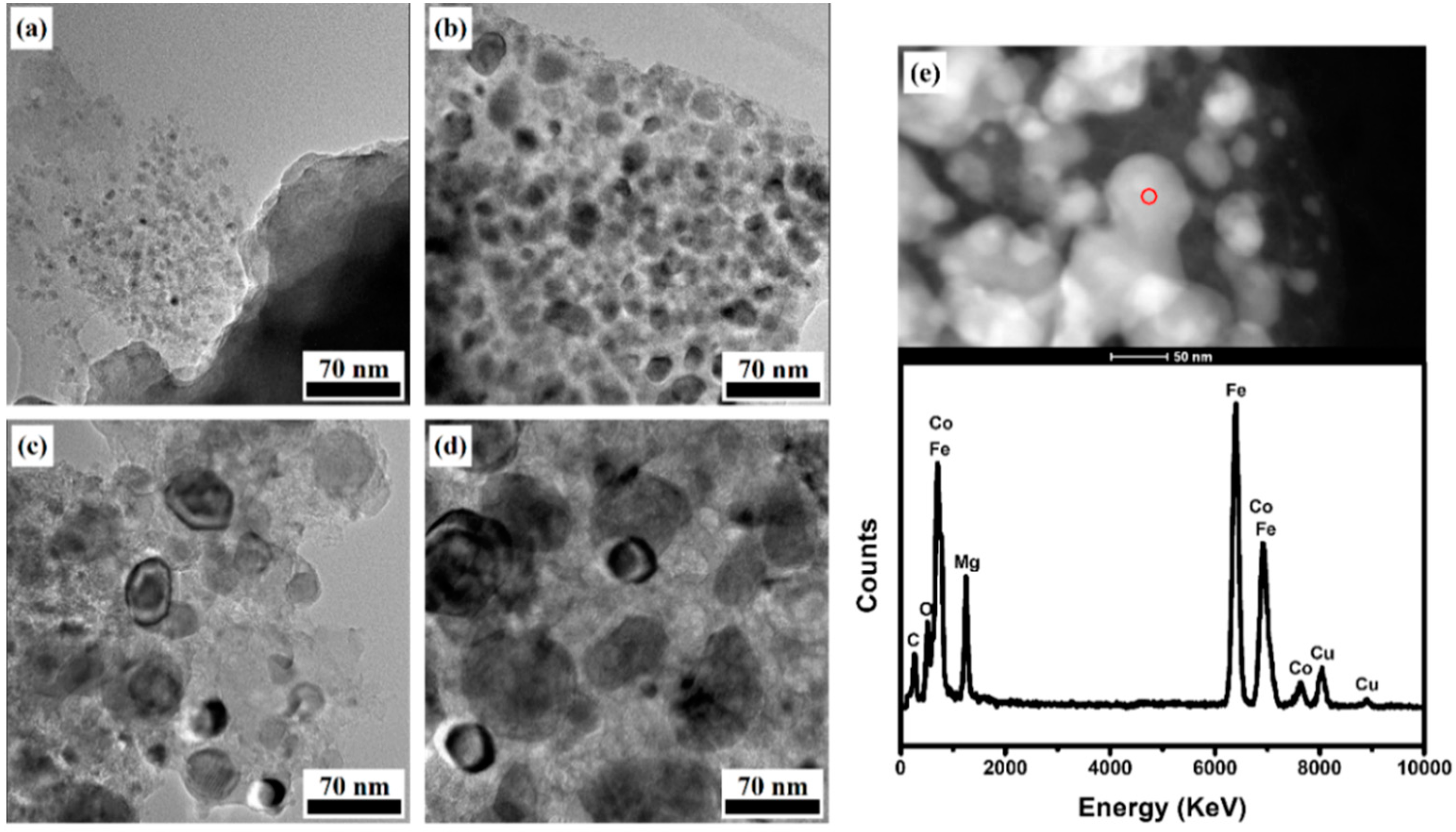
2.1. Characterization of Fe–Co/MgO Catalyst after Reduction

Energy-dispersive X-ray spectroscopy (EDX) analysis was carried out to confirm the concentration of elements of the Fe–Co/MgO catalyst prepared at various reduction temperatures. Some organic materials are present within the catalyst obtained by the sol-gel technique, and they still remain in the catalyst after reduction process [23]. Figure 1 shows that the iron and cobalt atomic % were increased from 4.09 to 14.27 and from 2.07 to 7.71, respectively, when reduction temperature increased from 600 to 900 °C, while the oxygen and carbon contents within catalysts were decreased. It is considered that catalytic hydrogenation can be generated by transition metal particles during the reduction of catalyst [24,25]. As a result, the organic materials are more removed when the reduction temperature is increased, and the proportion of the metal components in the catalyst is steadily increased. In addition, the atomic % ratio of iron to cobalt was found to be about 1.9 in all catalysts regardless of reduction temperatures.
Figure 2 shows the diffraction pattern of elements in the Fe–Co/MgO catalyst reduced at various temperature. The X-ray Diffraction (XRD) peaks clearly present metallic iron (zero-valent iron, JCPDS card No. 00-006-0696), cobalt oxide (JCPDS card No. 01-070-2855) and magnesium oxide (periclase, JCPDS card No. 01-071-1176) phases [26,27,28,29]. All the peaks become narrow and sharpen with increasing reduction temperature. It means that the degree of crystallinity of identified elements are increased as higher reduction temperature [20]. Especially, the peak intensity of iron which is observed at 2θ = 44°, 65°, and 82° is much increased as reduction temperature increases. The XRD peaks of both the cobalt oxide and magnesium oxides appeared at almost the same positions, and it is difficult to distinguish each peak clearly [26,27]. However, the peak intensity of the cobalt oxide becomes high as reduction temperature increases. The size of metallic iron particle within the catalyst is obtained by Scherrer equation analysis [30,31]. According to the calculation, the size of metallic iron particles was 8.2, 16.8, 29.0, and 40.4 nm, respectively, while reduction temperature was increased from 600 to 900 °C. This result can be explained by the fact that the agglomeration of metallic iron atoms in the catalyst is much activated when reduction temperature is higher.
Figure 3 shows transmission electron microscope (TEM) images of catalyst particles within the Fe–Co/MgO catalyst with different reduction temperature. We also observed metallic catalysts (dark spherical particles) which showed about 1.9 atomic % ratio of Fe to Co by TEM-EDX on the MgO support material (Figure 3e). The size of metallic catalyst particles was much increased and the uniformity of the particle size became poor according to increased reduction temperature. The agglomeration of metallic catalyst particles became stronger at a higher reduction temperature, resulting in the large size and the non-uniform size. The size distribution of metallic particles was presented in the range of 6.3~12.9, 8.2~24.8, 15.0~38.8, and 11.6~57.7 when reduction temperature of catalyst was increased from 600 to 900 °C. This result is well agreed with XRD analysis, which showed the size of metallic iron particles calculated by Scherrer equation. The representative value of the metal catalyst size obtained from TEM analysis is similar to the calculated value of the metal catalyst by Scherrer equation.

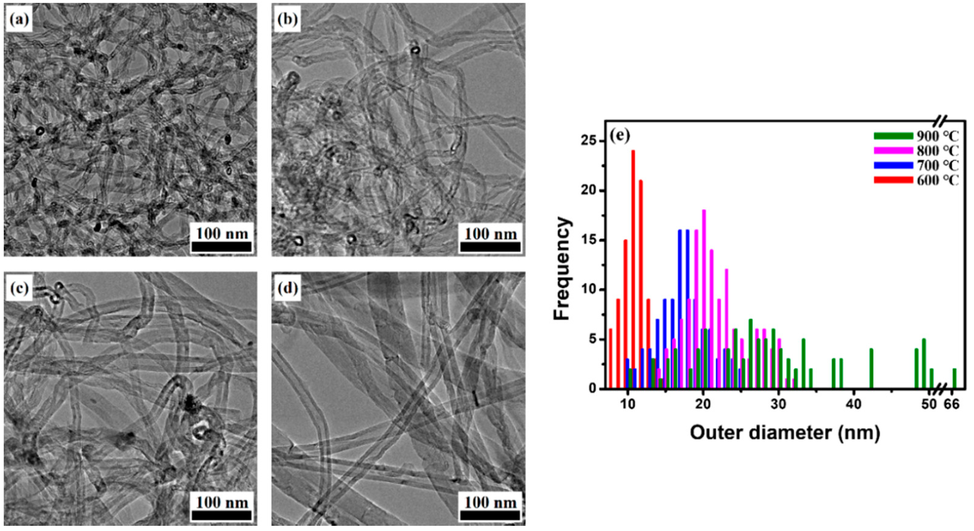
2.2. Analysis of Synthesized MWCNTs Using Catalyst Reduced at Different Temperature

Figure 4 shows scanning electron microscope (SEM) images of CNTs grown by using the Fe–Co/MgO catalyst with different reduction temperature. Except for the reduction temperature of the catalyst, the growth conditions of CNTs such as growth temperature, a reaction gas flow rate and a reaction time were the same in all experiments. From SEM observation, the curly and entangled CNTs were grown on the catalysts without carbon particles. The average diameter of CNTs is increased with increasing reduction temperature and non-uniformity of CNTs is increased (Figure 4d). This result follows the size of metallic catalyst particles according to increased reduction temperature.
Figure 5 shows the TEM images of the synthesized CNTs by using the Fe–Co/MgO catalyst with different reduction temperature. The as-grown CNTs indicate multi-walled structure (namely MWCNTs) with good purity but the uniformity of diameter distribution of MWCNTs revealed to be very poor at a higher reduction temperature. For exact investigation of the effect of reduction temperature on the diameter distribution of MWCNTs, around 100 MWCNTs per one sample were selected and the diameter of MWCNTs was measured from the respective TEM images. TEM analysis indicates that the outer diameter of the as-grown MWCNTs is in the range of 8~15, 10~26, 14~32, and 10~65 nm, respectively, when reduction temperature increases from 600 to 900 °C. It clearly reveals that the average diameter of the grown MWCNTs was increased with increasing reduction temperature and the diameter distribution was widened. This result follows the size of metallic catalyst particles and the uniformity of size distribution of metallic catalyst particle according to increased reduction temperature as shown in Figure 3.
Figure 6 shows the high resolution TEM (HRTEM) images of as-grown MWCNTs with different reduction temperature. The HRTEM images reveal that MWCNTs have parallel multiple layers of a graphene sheet with an inside hollow in all samples. With increasing reduction temperature from 600 to 900 °C, the MWCNTs indicate average numbers of graphene sheets from 10 to 46. It reveals that the numbers of graphene sheets follow the outer diameter of CNTs. In addition, when the reduction temperature goes up, the graphene sheets indicate well-ordered and higher crystallinity structure (Figure 6 inset). It is considered that higher crystallinity of graphite sheet is mainly caused by more active reaction of carbon atoms inside a higher crystalline Fe catalyst particle. The surface of an outer wall of MWCNTs shows formation of amorphous graphite sheet due to reaction of residual gas at lower temperature after power off.
Raman analysis was used to determine the degree of graphitization of CNTs. Figure 7a shows Raman spectrum of the as-grown MWCNTs by using a 514 nm laser. Raman spectrum of CNTs shows two main peaks, one is the G-band (1589.2 cm−1) induced by a degree of graphitization and the other is the D-band (1352.9 cm−1) indicated a degree of disorder of the graphite structure or the present of amorphous carbon deposited on the surface of outer wall [32]. The intensity ratio of G- and D-band (IG/ID) can be regarded as an index for an overall information of crystallinity of CNTs. The IG/ID ratio obtained from Figure 7a indicates an increase from 1.08, 1.17, 1.31 to 1.35, respectively, as reduction temperature increases as shown in Figure 7b. This result means that the catalyst reduced at a higher temperature is more favorable to get better-graphitized CNTs.
TGA analysis was used to determine the carbon content and purity of as-grown MWCNTs and understand overall crystallinity of MWCNTs. Figure 7c shows a comparative TGA weight loss curve of the as-grown MWCNTs. Purity of as-grown MWCNTs was about 86.5, 92.2, 93.4, and 93.1%, respectively at reduction temperature of 600, 700, 800, and 900 °C and the burn-out temperature of MWCNTs was increased as the reduction temperature increases. The derivative thermogravimetric (DTG) curve also shows that relative crystallinity of MWCNTs becomes higher with increasing reduction temperature as shown in Figure 7d. This result reveals that the higher crystalline metal catalysts induce the higher crystalline CNTs due to better graphitization of graphene sheets.

3. Experimental Section

3.1. Fabrication of Catalyst and the Growth of MWCNTs

The catalyst with mole ratio at Fe:Co:MgO = 2:1:5 was fabricated by a sol-gel method [33,34]. Magnesium nitrate hexahydrate [Mg(NO3)2·6H2O], iron nitrate nonahydrate [Fe(NO3)3·9H2O] and cobalt nitrate hexahydrate [Co(NO3)2·6H2O] were mixed in 50 mL of deionized water. Then, the citric acid was inserted to the mixture to make a homogenous solution. The solution was stirred at 80 °C for 30 min, and it was baked in the oven at 120 °C for 12 h. As a result, the solution became to a catalyst powder. Finally, the catalyst powder was reduced by using a furnace in H2 (100 sccm) ambient from 600 to 900 °C for 1h in a quartz tube (inner diameter 2.5 inches). For the growth of CNTs, an alumina boat containing 15 mg of the Fe–Co/MgO catalyst was loaded at the middle position of a quartz tube (inner diameter 1 inch) and then the reactor was heated up to growth temperature of 750 °C in the Ar flow (300 sccm). When reactor temperature reached at 750 °C, the mixed gas of ethylene (150 sccm) and H2 (30 sccm) was introduced into the quartz tube for 30 min to grow CNTs. After finishing the CNT growth, the reactor was cooled to room temperature in Ar atmosphere.

3.2. Characterization of Catalyst and MWCNTs

The fabricated catalyst was characterized by X-ray Diffraction (XRD, SmartLab, Neu-Isenburg, Germany) to examine the crystallite size and the crystal phase. XRD analysis was performed with Cu Kα (λ = 1.54 Å) at 45 kV and 200 mA, and XRD patterns were obtained in the 2θ ranging from 5 to 90° and a measurement time of 2 s per point.
Energy-dispersive X-ray spectroscopy (EDX) and scanning electron microscope (SEM) were performed on a Hitachi 4800 (Tokyo, Japan). An accelerating voltage of 15 kV was employed for EDX and SEM analysis. EDX characterization of catalysts after reduction was performed in order to get element information about their chemical composition.
The synthesized CNTs were analyzed by transmission electron microscope (TEM, FEI TECNAI G2 F30ST, Waltham, MA, USA), Raman spectroscope (HR-800 with a laser wavelength of 514 nm and power of 1.67 mW, Kyoto, Japan) and thermogravimetric analysis (TGA, TA Q50 instrument, New Castle, DE, USA). TEM analysis was carried out to verify a diameter distribution and structural of graphene sheets of CNTs, Raman was performed to evaluate crystallinity of CNTs and TGA a was performed in air ambient at 60 mL/min with a heating rate of 10 °C/min to obtain carbon content and overall crystallinity of CNTs.

4. Conclusions

The reduction temperature effect of the Fe–Co/MgO catalyst on the diameter and crystallinity of MWCNTs have been studied. Reduction temperature of the Fe–Co/MgO catalyst directly affects the size and crystallinity of metal catalyst particles, which determine properties of MWCNTs such as a diameter and crystallinity. With increasing reduction temperature, metal catalysts had a larger particle size and better crystallinity, resulting in the growth of MWCNTs with a widened diameter distribution and improved crystallinity. The synthesized MWCNTs showed increased diameters in the range of 8~15, 10~26, 14~32, and 10~65 nm, respectively by increasing reduction temperature of the Fe–Co/MgO catalyst from 600 to 900 °C, and enhanced crystallinity (IG/ID ratio) of 1.08, 1.17, 1.31, to 1.35, respectively. These results indicate that reduction temperature of catalyst is very important parameters to control properties of MWCNTs. We believe that our results can be very helpful to understand and control characteristics of CNTs in order to synthesize optimized CNTs for various applications.

Author Contributions

Investigation, Formal analysis, Writing-original draft, P.K.; Data curation, Writing-review and editing, Project administration C.J.L.

Funding

This research received no external funding.

Acknowledgments

This work was supported by Brain Korea 21 Plus Project through the Ministry of Education in Korea and Korea Basic Science Institute (KBSI).

Conflicts of Interest

The authors declare no conflict of interest.

References

  1. Iijima, S. Helical microtubules of graphitic carbon. Nature 1991, 354, 56–58. [Google Scholar] [CrossRef]
  2. Baughman, R.H.; Zakhidov, A.A.; de Heer, W.A. Carbon nanotubes—The route toward applications. Science 2002, 297, 787–792. [Google Scholar] [CrossRef] [PubMed]
  3. De Volder, M.F.L.; Tawfick, S.H.; Baughman, R.H.; Hart, A.J. Carbon nanotubes: Present and future commercial applications. Science 2013, 339, 535–539. [Google Scholar] [CrossRef] [PubMed]
  4. Shin, D.H.; Yun, K.N.; Jeon, S.G.; Kim, J.I.; Saito, Y.; Milne, W.I.; Lee, C.J. High performance field emission of carbon nanotube film emitters with a triangular shape. Carbon 2015, 89, 404–410. [Google Scholar] [CrossRef]
  5. Cao, Q.; Rogers, J.A. Ultrathin films of single-walled carbon nanotubes for electronics and sensors: A review of fundamental and applied aspects. Adv. Mater. 2009, 21, 29–53. [Google Scholar] [CrossRef]
  6. Mirri, F.; Ma, A.W.K.; Hsu, T.T.; Behabtu, N.; Eichmann, S.L.; Young, C.C.; Tsentalovich, D.E.; Pasquali, M. High-performance carbon nanotube transparent conductive films by scalable dip coating. ACS Nano 2012, 6, 9737–9744. [Google Scholar] [CrossRef] [PubMed]
  7. Lota, G.; Fic, K.; Frackowiak, E. Carbon nanotubes and their composites in electrochemical applications. Energ. Environ. Sci. 2011, 4, 1592–1605. [Google Scholar] [CrossRef]
  8. Odom, T.W.; Huang, J.L.; Kim, P.; Lieber, C.M. Atomic structure and electronic properties of single-walled carbon nanotubes. Nature 1998, 391, 62–64. [Google Scholar] [CrossRef]
  9. Popov, V.N. Carbon nanotubes: Properties and application. Mater. Sci. Eng. R 2004, 43, 61–102. [Google Scholar] [CrossRef]
  10. Eatemadi, A.; Daraee, H.; Karimkhanloo, H.; Kouhi, M.; Zarghami, N.; Akbarzadeh, A.; Abasi, M.; Hanifehpour, Y.; Joo, S.W. Carbon nanotubes: Properties, synthesis, purification, and medical applications. Nanoscale Res. Lett. 2014, 9, 393. [Google Scholar] [CrossRef] [PubMed]
  11. Arora, N.; Sharma, N.N. Arc discharge synthesis of carbon nanotubes: Comprehensive review. Diam. Relat. Mater. 2014, 50, 135–150. [Google Scholar] [CrossRef]
  12. Maser, W.K.; Munoz, E.; Benito, A.M.; Martinez, M.T.; de la Fuente, G.F.; Maniette, Y.; Anglaret, E.; Sauvajol, J.L. Production of high-density single-walled nanotube material by a simple laser-ablation method. Chem. Phys. Lett. 1998, 292, 587–593. [Google Scholar] [CrossRef]
  13. Lyu, S.C.; Liu, B.C.; Lee, S.H.; Park, C.Y.; Kang, H.K.; Yang, C.W.; Lee, C.J. Large-scale synthesis of high-quality single-walled carbon nanotubes by catalytic decomposition of ethylene. J. Phys. Chem. B 2004, 108, 1613–1616. [Google Scholar] [CrossRef]
  14. Kumar, M.; Ando, Y. Chemical vapor deposition of carbon nanotubes: A review on growth mechanism and mass production. J. Nanosci. Nanotechnol. 2010, 10, 3739–3758. [Google Scholar] [CrossRef] [PubMed]
  15. Magrez, A.; Seo, J.W.; Smajda, R.; Mionic, M.; Forro, L. Catalytic cvd synthesis of carbon nanotubes: Towards high yield and low temperature growth. Materials 2010, 3, 4871–4891. [Google Scholar] [CrossRef] [PubMed]
  16. Prasek, J.; Drbohlavova, J.; Chomoucka, J.; Hubalek, J.; Jasek, O.; Adam, V.; Kizek, R. Methods for carbon nanotubes synthesis-review. J. Mater. Chem. 2011, 21, 15872–15884. [Google Scholar] [CrossRef]
  17. Lee, C.J.; Lyu, S.C.; Cho, Y.R.; Lee, J.H.; Cho, K.I. Diameter-controlled growth of carbon nanotubes using thermal chemical vapor deposition. Chem. Phys. Lett. 2001, 341, 245–249. [Google Scholar] [CrossRef]
  18. Rummeli, M.H.; Kramberger, C.; Schaffel, F.; Borowiak-Palen, E.; Gemming, T.; Rellinghaus, B.; Jost, O.; Loffler, M.; Ayala, P.; Pichler, T.; et al. Catalyst size dependencies for carbon nanotube synthesis. Phys. Status Solidi B 2007, 244, 3911–3915. [Google Scholar] [CrossRef]
  19. Huang, Y.L.; Vlachos, D.G.; Chen, J.G.G. Synthesis of rigid and stable large-inner-diameter multiwalled carbon nanotubes. RSC Adv. 2012, 2, 2685–2687. [Google Scholar] [CrossRef]
  20. Yeoh, W.M.; Lee, K.Y.; Chai, S.P.; Lee, K.T.; Mohamed, A.R. Effective synthesis of carbon nanotubes via catalytic decomposition of methane: Influence of calcination temperature on metal-support interaction of co-mo/mgo catalyst. J. Phys. Chem. Solids 2013, 74, 1553–1559. [Google Scholar] [CrossRef]
  21. Tran, K.Y.; Heinrichs, B.; Colomer, J.F.; Pirard, J.P.; Lambert, S. Carbon nanotubes synthesis by the ethylene chemical catalytic vapour deposition (CCVD) process on Fe, Co, and Fe–Co/Al2O3 sol-gel catalysts. Appl. Catal. A Gen. 2007, 318, 63–69. [Google Scholar] [CrossRef]
  22. Pelech, I.; Narkiewicz, U.; Kaczmarek, A.; Jedrzejewska, A. Preparation and characterization of multi-walled carbon nanotubes grown on transition metal catalysts. Pol. J. Chem. Technol. 2014, 16, 117–122. [Google Scholar] [CrossRef] [Green Version]
  23. Li, Y.; Liu, J.; Wang, Y.Q.; Wang, Z.L. Preparation of monodispersed Fe–Mo nanoparticles as the catalyst for cvd synthesis of carbon nanotubes. Chem. Mater. 2001, 13, 1008–1014. [Google Scholar] [CrossRef]
  24. Datta, S.S.; Strachan, D.R.; Khamis, S.M.; Johnson, A.T.C. Crystallographic etching of few-layer graphene. Nano Lett. 2008, 8, 1912–1915. [Google Scholar] [CrossRef] [PubMed]
  25. Ci, L.J.; Song, L.; Jariwala, D.; Elias, A.L.; Gao, W.; Terrones, M.; Ajayan, P.M. Graphene shape control by multistage cutting and transfer. Adv. Mater. 2009, 21, 4487–4491. [Google Scholar] [CrossRef]
  26. Garces, L.J.; Hincapie, B.; Zerger, R.; Suib, S.L. The effect of temperature and support on the reduction of cobalt oxide: An in situ x-ray diffraction study. J. Phys. Chem. C 2015, 119, 5484–5490. [Google Scholar] [CrossRef]
  27. Hassan, N.A.; El-Molla, S.A.; Mohamed, G.M.; Fagal, G.A. Effect of ZrO2-doping of nanosized Fe2O3/MgO system on its structural, surface and catalytic properties. Mater. Res. Bull. 2012, 47, 2655–2661. [Google Scholar] [CrossRef]
  28. Mao, Z.; Wu, Q.Z.; Wang, M.; Yang, Y.S.; Long, J.; Chen, X.H. Tunable synthesis of SiO2-encapsulated zero-valent iron nanoparticles for degradation of organic dyes. Nanoscale Res. Lett. 2014, 9, 501. [Google Scholar] [CrossRef] [PubMed]
  29. Sun, Y.P.; Li, X.Q.; Cao, J.S.; Zhang, W.X.; Wang, H.P. Characterization of zero-valent iron nanoparticles. Adv. Colloid Interface Sci. 2006, 120, 47–56. [Google Scholar] [CrossRef] [PubMed]
  30. Maurin, G.; Stepanek, I.; Bernier, P.; Colomer, J.F.; Nagy, J.B.; Henn, F. Segmented and opened multi-walled carbon nanotubes. Carbon 2001, 39, 1273–1278. [Google Scholar] [CrossRef]
  31. Jang, J.W.; Lee, K.W.; Oh, I.H.; Lee, E.M.; Kim, I.M.; Lee, C.E.; Lee, C.J. Magnetic Fe catalyst particles in the vapor-phase-grown multi-walled carbon nanotubes. Solid State Commun. 2008, 145, 561–564. [Google Scholar] [CrossRef]
  32. Dresselhaus, M.S.; Dresselhaus, G.; Jorio, A. Unusual properties and structure of carbonnanotubes. Annu. Rev. Mater. Res. 2004, 34, 247–278. [Google Scholar] [CrossRef]
  33. Irurzun, V.M.; Tan, Y.Q.; Resasco, D.E. Sol-gel synthesis and characterization of Co–Mo/silica catalysts for single-walled carbon nanotube production. Chem. Mater. 2009, 21, 2238–2246. [Google Scholar] [CrossRef]
  34. Dubey, P.; Choi, S.K.; Kim, B.; Lee, C.J. Synthesis of thin-multiwalled carbon nanotubes by Fe–Mo/MgO catalyst using sol-gel method. Carbon Lett. 2012, 13, 99–108. [Google Scholar] [CrossRef]
Figure 1. (a) Iron and Cobalt atomic % and (b) Oxygen and Carbon atomic % according to reduction temperature of the Fe–Co/MgO catalyst.
Catalysts 08 00361 g001
Figure 2. X-ray Diffraction (XRD) analysis of Fe–Co/MgO catalyst as various reduction temperature.
Catalysts 08 00361 g002
Figure 3. TEM image of catalyst particles reduced at (a) 600, (b) 700, (c) 800 and (d) 900 °C, respectively, and (e) TEM-EDX spectrum on the metallic catalyst (red ring).
Catalysts 08 00361 g003
Figure 4. Scanning electron microscope (SEM) image of CNTs grown by using the Fe–Co/MgO catalyst reduced at (a) 600, (b) 700, (c) 800, and (d) 900 °C, respectively.
Catalysts 08 00361 g004
Figure 5. TEM image of the as-synthesized MWNCTs using catalysts reduced at (a) 600, (b) 700, (c) 800, and (d) 900 °C; (e) for histograms of diameter distributions.
Catalysts 08 00361 g005
Figure 6. High resolution of TEM images of MWCNT using catalysts reduced at (a) 600, (b) 700, (c) 800, and (d) 900 °C, respectively.
Catalysts 08 00361 g006
Figure 7. (a) Raman spectroscopy (b) IG/ID ratio (c) thermogravimetric analysis (TGA) and (d) derivative thermogravimetric (DTG) analysis of MWCNTs according to reduction temperature of Fe–Co/MgO catalyst.
Catalysts 08 00361 g007

