Article

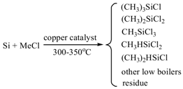
Controlled Synthesis of Heterostructured SnO2-CuO Composite Hollow Microspheres as Efficient Cu-Based Catalysts for the Rochow Reaction

1
State Key Laboratory of Advanced Special Steel, School of Materials Science and Engineering, Shanghai University, Shanghai 200072, China
2
State Key Laboratory of Multiphase Complex Systems, Institute of Process Engineering, Chinese Academy of Sciences, Beijing 100190, China
3
Institute of Chemical and Engineering Sciences, Agency for Science, Technology and Research (A*STAR), 1 Pesek Road, Jurong Island, Singapore 627833, Singapore
4
Institute of Industrial Chemistry and Energy Technology, Shenyang University of Chemical Technology, Shenyang 110142, China
*
Authors to whom correspondence should be addressed.
Catalysts 2018, 8(4), 144; https://doi.org/10.3390/catal8040144
Submission received: 7 March 2018 / Revised: 28 March 2018 / Accepted: 28 March 2018 / Published: 3 April 2018

Abstract

:
In this work, we report the design and synthesis of a series of heterostructured SnO2-CuO hollow microspherical catalysts (H-SnO2(x)-CuO, x is the weight ratio of Sn/Cu) for the Rochow reaction. The microspherical catalysts with nanosheets and nanoparticles as building blocks were prepared by a facile one-pot hydrothermal method coupled with calcination. When tested for the Rochow reaction, the prepared H-SnO2(0.2)-CuO composite exhibited higher dimethyldichlorosilane selectivity (88.2%) and Si conversion (36.7%) than the solid CuO, hollow CuO and other H-SnO2(x)-CuO microspherical samples, because in the former there is a stronger synergistic interaction between CuO and SnO2.

Graphical Abstract

1. Introduction

In material synthesis, how to obtain materials with well-defined structures/shapes is one of the major goals, as each of their application is dependent on their physicochemical attributes and morphologies. Recently, nanostructures with various shapes including nanowires [1], nanotubes [2], nanorods [3] and hollow nanospheres [4] have been reported. Among them, hollow nanostructures are of particular interest owing to their unique structural features such as high surface area and fast diffusion capability, which are of importance to many applications such as catalysis [5,6], sensors [7], pollution treatment [8] and energy conversion [9]. For example, it was reported that CuO and NiO hollow nanospheres showed high catalytic activity and excellent stability for the hydrogenation of 4-nitrophenol [10], while a three-dimensional (3D) graphene network encapsulating SnO2 hollow spheres exhibited outstanding electrochemical properties as an anode material for lithium-ion batteries [11]. However, most of these reported hollow structures are made up of only single oxide component, limiting their wider application. In principle, hollow heterostructures containing two or more kinds of metal oxide components with specific morphologies will have more abundant structural features such as various synergistic interactions among different components, thus potentially having more substantial applications [12,13]. However, the controlled synthesis of these multi-component complex systems is still highly more challenging.
One of the applications for multi-Cu component containing system is for the Rochow reaction. This reaction is used to synthesize methylchlorosilanes, which are important intermediates in the organosilane industry [14]. As shown in Scheme 1, this reaction often yields various products, in which (CH3)2SiCl2 (M2) is the most needed, as it is widely used for the manufacture of organosilicon products such as silicon rubber and silicon oil. Therefore, to enhance the selectivity and yield of M2, high-performance Cu-based catalysts are always desired. In the past decades, various catalyst systems have been reported [15,16,17]. In our previous work, many CuO catalysts with specific morphologies and structures have also been prepared and tested for the Rochow reaction. For instance, we observed that the flower-like CuO microspheres displayed a higher M2 selectivity and Si conversion than the commercial CuO catalyst with irregular morphology [18]; the leaf-like CuO nanostructure showed enhanced catalytic properties due to its largely exposed {001} plane that could facilitate formation of more Cu3Si active phase during the reaction [19]; most recently, we demonstrated that the rambutan-like CeO2-CuO hollow microspheres exhibited superior catalytic performances to their solid counterpart and pure CuO, because of the more intimate contact of CuO with Si powder and the synergistic effect between CeO2 and CuO in the former [20]. These results indicate that the M2 selectivity and yield could be further improved by rationally controlling the morphology, structure and composition of Cu-based catalysts. Furthermore, it has been recognized that SnO2 is an outstanding promoter for the Rochow reaction [21,22]. In this sense, SnO2-CuO micro-nano composites with hollow heterostructures are most likely to be good catalyst candidates too. However, to our knowledge, so far, such a promising catalyst system has not been explored for the Rochow reaction.
Catalysts 08 00144 i001
Herein, we report the preparation of heterostructured SnO2-CuO composite hollow microspheres with nanosheets and nanoparticles as building blocks and with various Sn/Cu ratios using a facile bottom-up strategy. When employed as catalysts for the Rochow reaction, the SnO2-CuO hollow heterostructures showed a higher selectivity of M2 and Si conversion than the solid CuO, hollow CuO and commercial catalyst, particularly at the optimal Sn/Cu ratio. Moreover, the structure-dependent catalytic attributes and the reaction mechanism are also studied.

2. Results and Discussion

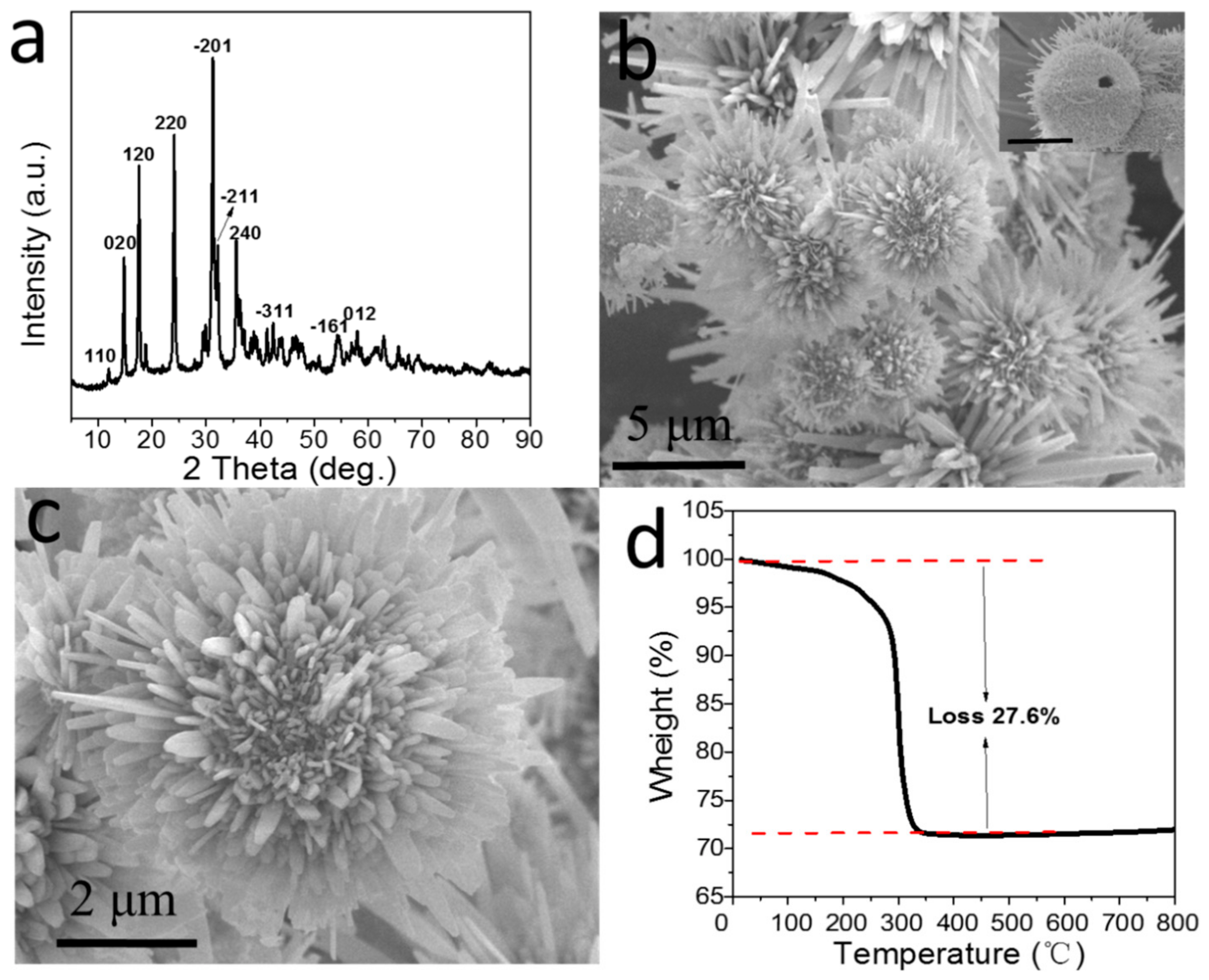
2.1. Characterization of H-SnO2-CuO Precursor Particle

The XRD pattern of the collected precursor before calcination shows that the diffraction peaks match well with those of monoclinic basic cupric carbonate (Cu2(OH)2CO3) (JCPDS No. 01-072-0075) (Figure 1a). The formation of Cu2(OH)2CO3 should be the result of the chemical reaction between Cu(CH3COO)2·H2O and Na2CO3 solution, which is presented as follows:
CO32 + H2O → HCO3 + OH
HCO3 + H2O → H2O + CO2 + OH
The low-magnification FESEM image shows that the Cu2(OH)2CO3 precursor is in the shape of microspheres and all particles are uniform with an average size of ca. 5 μm (Figure 1b). From a typical crashed microsphere (Inset of Figure 1b), it could be clearly observed that the precursor particle possesses a hollow structure. The high-magnification FESEM image further demonstrates that some disorder nanosheets are stretched out onto the microspherical surface (Figure 1c). The TG curve of this uncalcined sample shows a weight loss of about 27.6% from 200 to 350 °C in air, matching well with 27.9%, the theoretical value for the decomposition process from Cu2(OH)2CO3 to CuO (Figure 1d).

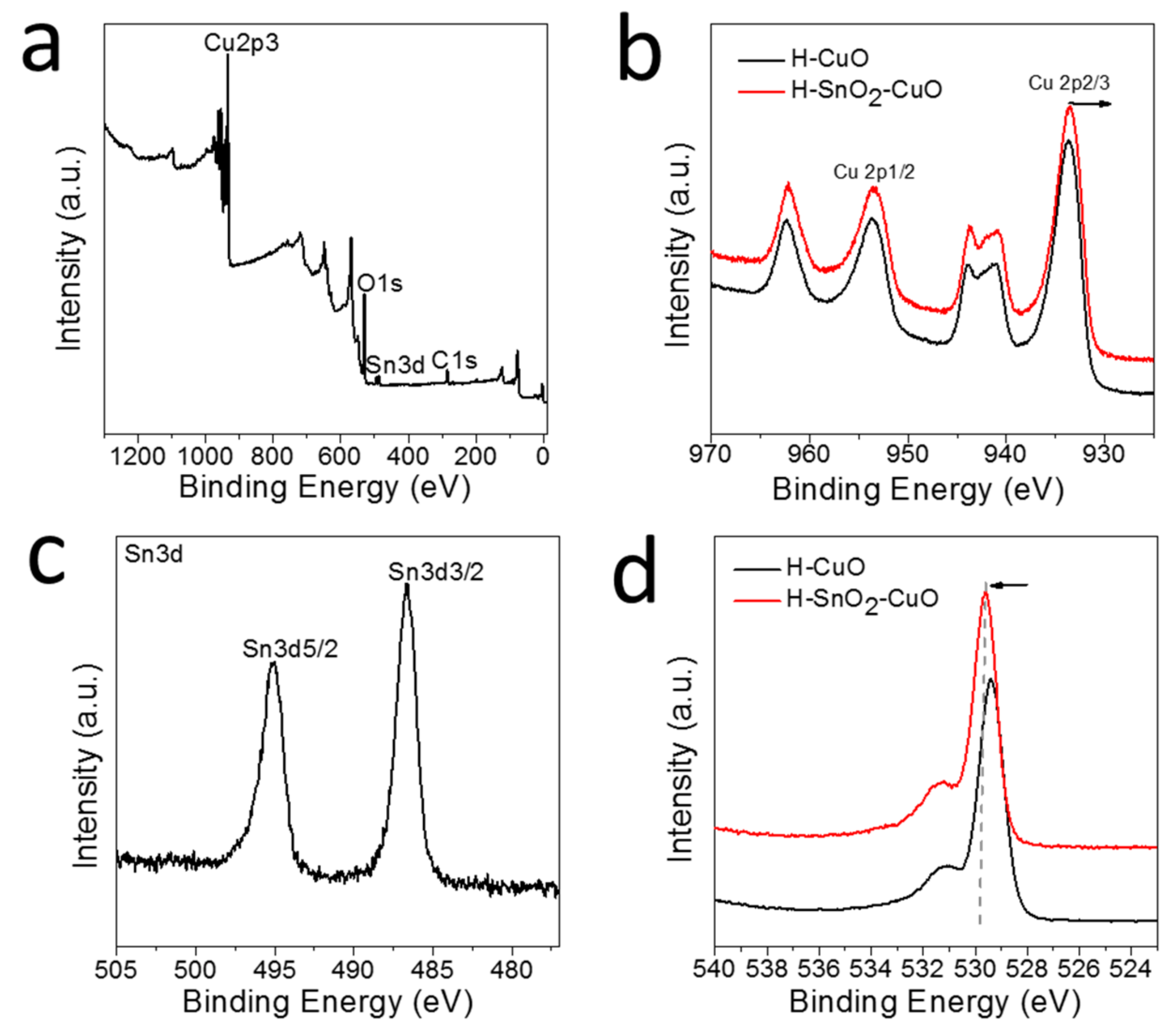
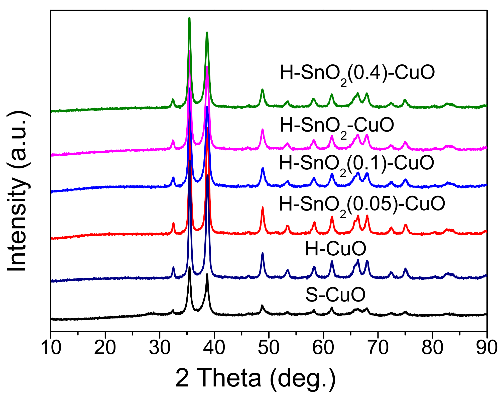
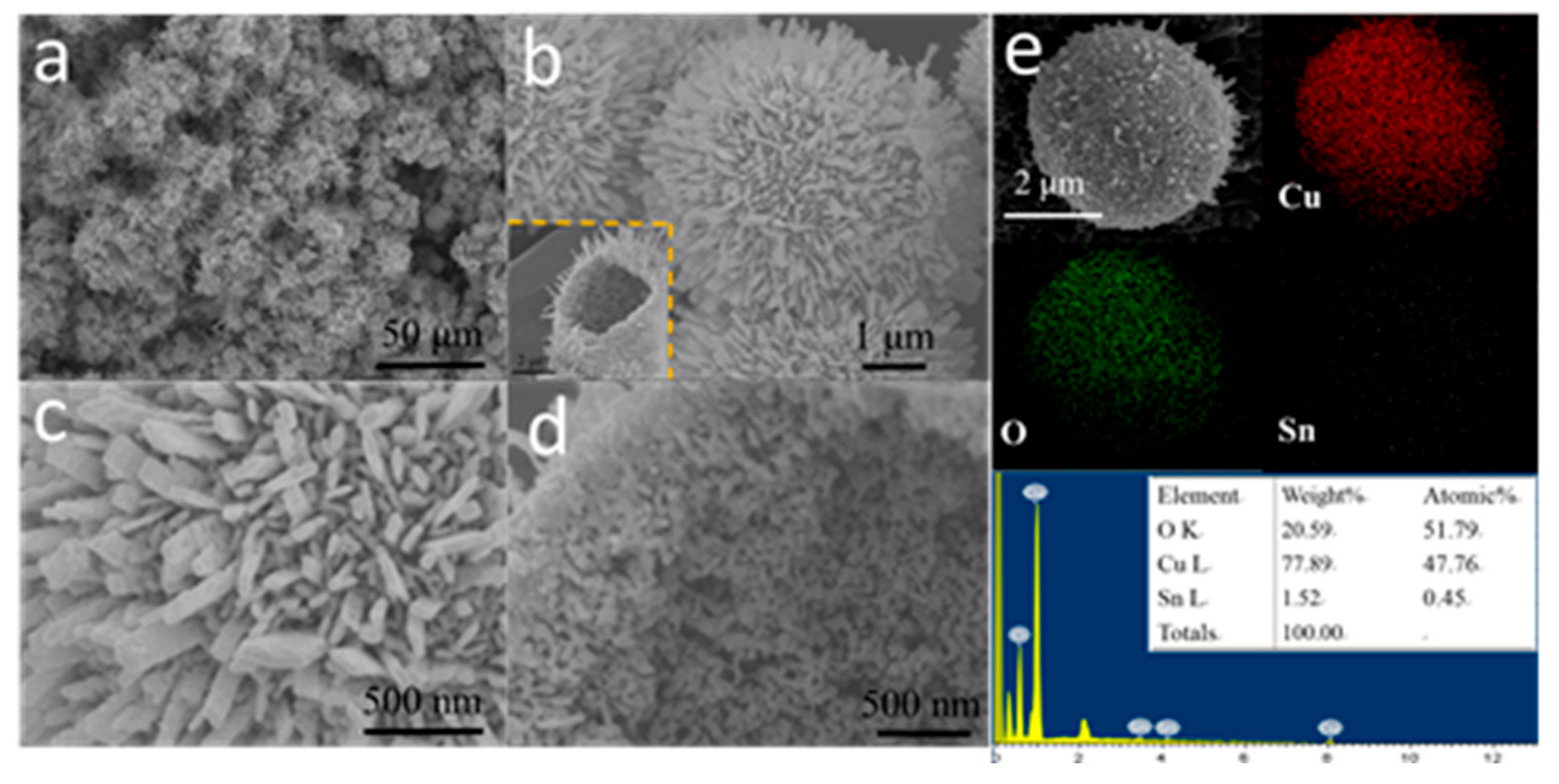
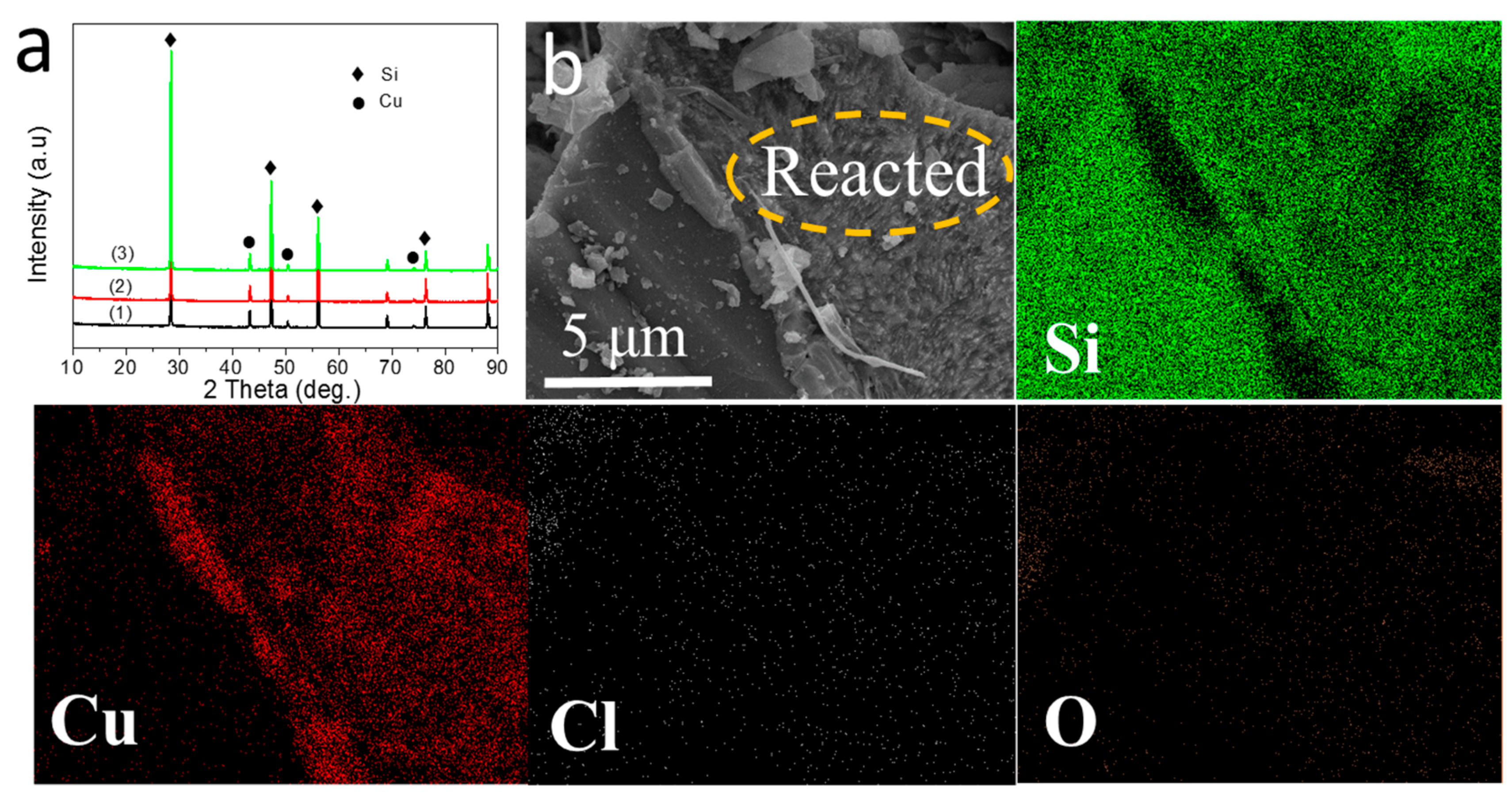
2.2. Characterization of H-SnO2-CuO

Figure 2 exhibits the XRD results of all the obtained products after calcination, including hollow SnO2-CuO microspheres (denoted as H-SnO2-CuO), hollow CuO microspheres (denoted as H-CuO) and solid CuO microspheres (denoted as S-CuO). The diffraction peaks observed at 2θ values of 32.5°, 35.5°, 38.7°, 48.7°, 53.4°, 58.3°, 61.5°, 66.2°, 68.1° and 72.4° correspond respectively to (110), (−111), (111), (−202), (020), (202), (−113), (−311), (220) and (311) lattice planes of the monoclinic CuO phase (JCPDS No. 01-005-0611). However, no obvious peak matching with crystalline Sn species could be found, probably due to its small amount or small size. Additionally, no traces of other impurities such as Cu2O or Cu2(OH)2CO3 can be observed. As we know, particle size often impacts catalytic activity [23]. Hence, the CuO nanocrystal sizes in these materials are calculated from the diffraction peaks at 2θ values of 35.5° using the Scherrer formula, the results are listed in Table 1. It is clearly seen that the average grain size of CuO in H-SnO2-CuO sample is 22.9 nm, which is smaller than that in H-CuO (42.1 nm), indicating that the CuO particle size could be reduced through introducing Sn. Moreover, the BET surface area and pore volume of various samples is given in Table 1. It can be seen that all H-SnO2(x)-CuO composites have similar surface areas and the pore volumes but which are much larger than those of S-CuO.
The measured low-magnification FESEM image shows that H-SnO2-CuO possesses similar morphology to its precursor particle, which is also in the shape of hollow spheres with an average size of ca. 5 μm (Figure 3a,b). As revealed by the magnified images shown in Figure 3c,d, the CuO shell is constructed by interconnected disordered nanoparticles and nanosheets. The size of the primary nanoparticles is typically about 20 nm. A nearly 91% of morphological yield of this type can be achieved in our work. The SEM-EDS mapping of H-SnO2-CuO further reveals that the elements of Cu, O and Sn are homogeneously distributed throughout the entire particle (Figure 3e) and the weight ratio of Sn/Cu is measured to be about 0.19, which is close to the result of ICP-OES and the feeding ratio of the two precursors.
The XPS spectra of Cu 2p, Sn 3d and O 1s were shown in Figure 4 and the presence of Cu, Sn, O and C elements are confirmed by XPS analysis of H-SnO2-CuO (Figure 4a). From the XPS spectra of Cu 2p (Figure 4b), it can be seen that the major peaks at 933.5 and 953.6 eV can be assigned to Cu 2p3/2 and Cu 2p1/2 of CuO, respectively [24], which are accompanied with a satellite peak at ca. 943.8 eV. Comparing with that of H-CuO sample, Cu 2p3/2 peak has a slight shift and it has decreased by 0.2 eV for H-SnO2-CuO. Figure 4c shows the Sn 3d XPS spectrum of the H-SnO2-CuO sample. The binding energies of Sn 3d5/2 and Sn 3d3/2 are located at 495.0 and 486.6 eV, respectively, indicating that the Sn species exists in the form of Sn4+ [25]. The surface Cu/Sn ratios determined by XPS and the bulk Cu/Sn ratios given by ICP in all the H-SnO2(x)-CuO samples are both summarized in Table 1. Compared with the bulk counterpart (0.20), the weight ratio of Sn/Cu on the surface (0.42) is larger for H-SnO2-CuO sample, suggesting that Sn element mainly distributed on crystallite surface. The above results indicate a generation of synergistic interactions between CuO and SnO2 on the microsphere surface. The O 1s XPS spectra of H-CuO and H-SnO2-CuO are numerically fitted into two sub-bands, which is shown in Figure 4d. The lower binding energy peak at 529.2–530.0 eV is ascribed to the idiomatical surface lattice oxygen cohere with the metal cations (denoted as Olatt) and the higher one at 530.5–531.5 eV is chemisorbed oxygen (denoted as Oads) [26]. The measured binding energies of O 1s for the H-CuO and H-SnO2-CuO are different. Comparing with that of H-CuO sample, there is an increase of 0.2 eV of in the binding energy of Oads peak for H-SnO2-CuO, it is indicated that the introducing of Sn species could change the binding energy of O 1s obviously.
Figure 5 shows the detailed structural features of S-CuO, H-CuO and various H-SnO2(x)-CuO composites with different ratios. S-CuO also has a uniform spherical shape with a size of ca. 5 μm. However, unlike the above H-SnO2-CuO, it has a solid structure (Figure 5a). Through adjusting the feeding ratios of Sn/Cu in the synthesis, a series of samples with hollow structures can also be prepared, including H-CuO (Figure 5b), H-SnO2(0.05)-CuO (Figure 5c), H-SnO2(0.1)-CuO (Figure 5d) and H-SnO2(0.4)-CuO (Figure 5e,f). Compared to H-SnO2-CuO, these samples show no noticeable morphology and size changes. Moreover, the Sn/Cu weight ratios in all samples determined by ICP–OES are summarized in Table 1, which shows that adjustment of the ratio of metal precursors can control the final product composition.

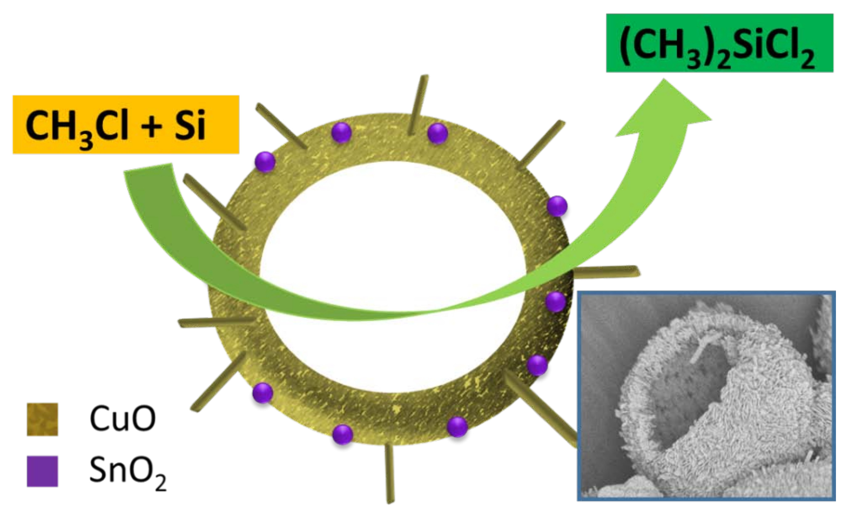
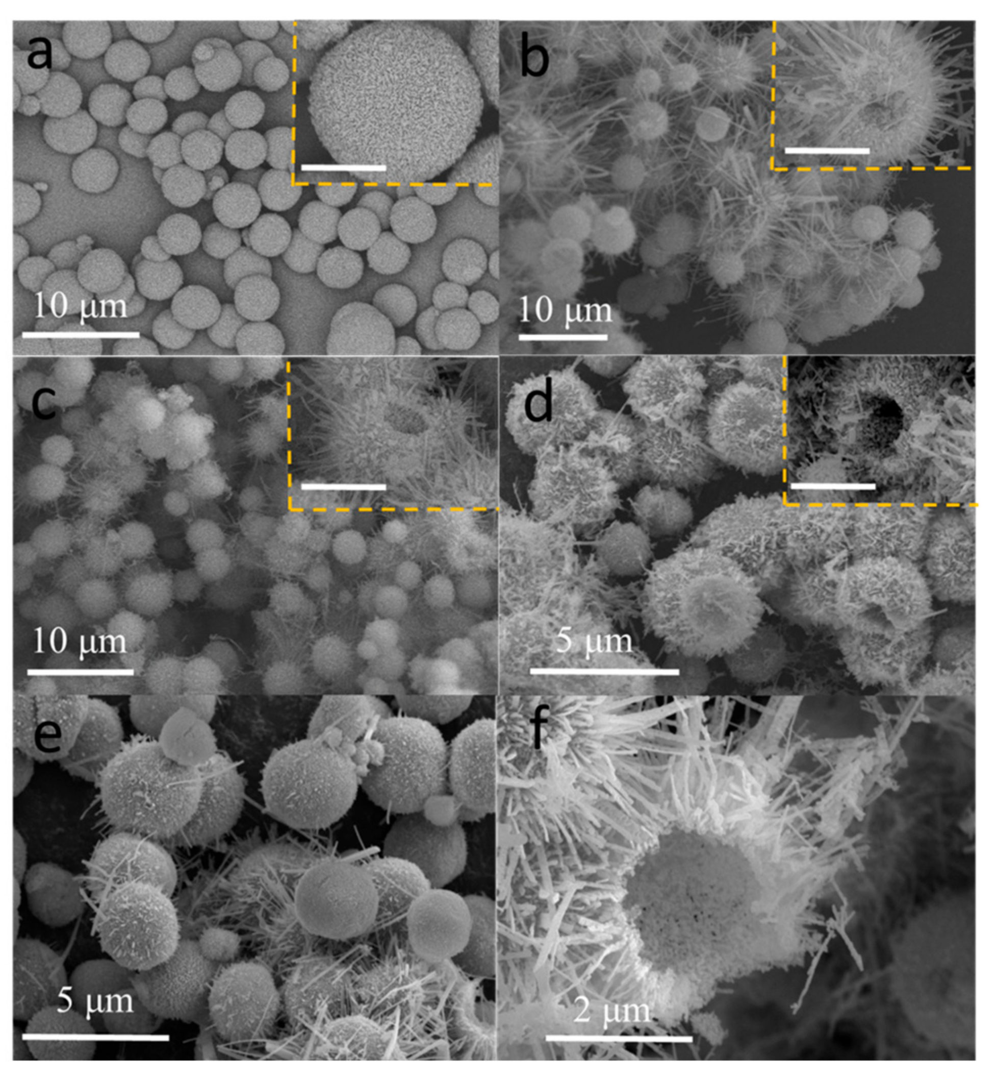
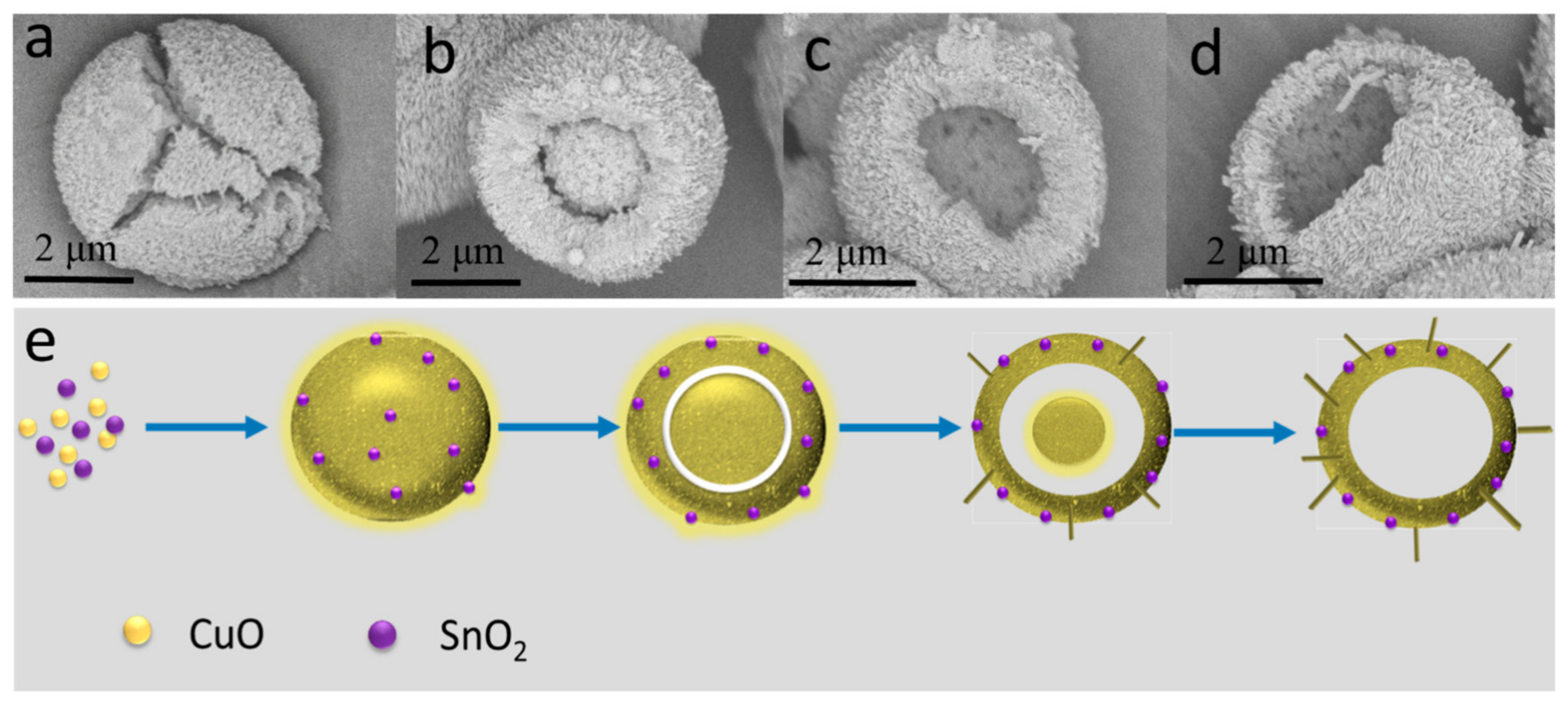
2.3. The Formation Mechanism of H-SnO2-CuO

To understand the formation mechanism of H-SnO2-CuO, a series of experiments with various reaction hours were performed. Figure 6a–d illustrate the morphological evolution of the particles along with the reaction processing. In the early stage of the reaction, a fast reaction among the large number of Cu2+ ions, the carbonate ions (CO32−) and the formed OH by hydrolysis of CO32− occurred, which yields many small nanoparticles of Cu2(OH)2CO3 with size of 20–30 nm (before 30 min, not shown). Meanwhile, Sn4+ ions are quickly hydrolyzed to produce SnO2 nanoparticles. After 1 h reaction, these unstable or energetic nanoparticles have spontaneously built up solid microspheres with smooth outside surfaces (Figure 6a). Compared with these small particles in the exterior regions, those in the interior regions of the microsphere have higher surface energies, thus crystallites under the outer surface are preferentially dissolved through the process of inside-out Ostwald ripening. As a result, when the reaction duration is prolonged to 4 h, the solid SnO2-CuO composites evolve to be a typical hollow yolk/shell structure, as displayed in Figure 6b. Additionally, it is also found that the primary nanoparticles in the outer surfaces become orderly arranged, because they are easier to be crystallized as compared to those in the internal surface. With the reaction up to 8 h, driven by minimization of surface energy, the inner core becomes smaller gradually until its complete disappearance. At the same time, the dissolved internal particles are recrystallized into tiny nanosheets, which finally develop into the “bundles of thorns” stretching out from the surface of these hollow spheres (Figure 6c). Eventually, after the reaction of 12 h, as depicted in Figure 6d, the initial solid structure has been evolved into a typical spherical structure with coarse surface anchoring with thick and large nanosheets. According to the above observations, this unique hollow structure evolution process follows the so-called “growth-cum-assembly” mechanism, which is depicted in Figure 6e. Such a process is very similar to that observed in the synthesis of CeO2-CuO hollow microsphere [20].

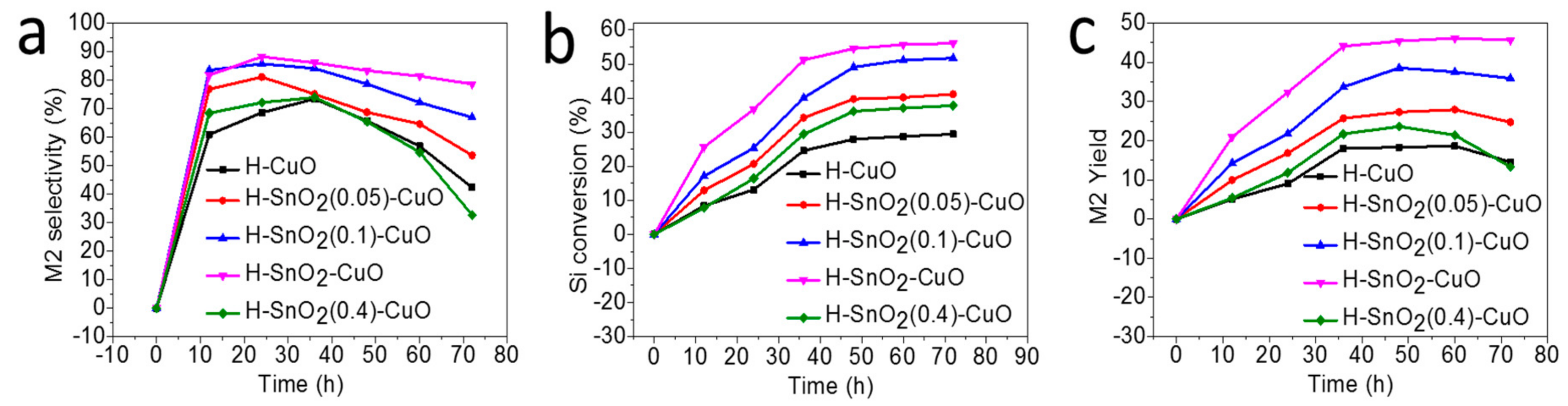
2.4. Catalytic Performance

Table 2 summarizes the catalytic performances of all the catalysts in Rochow reaction measured at 325 °C for 24 h under atmospheric pressure. S-SnO2 seems to be inactive. S-CuO also has a poor catalytic activity, with M2 selectivity and Si conversion being 61.2% and 7.9%, respectively. H-CuO shows a slightly better performance (68.6% of M2 selectivity and 13.1% of Si conversion), verifying the advantage of the hollow structure. The obvious improvement in catalytic performance is observed after introduction of SnO2 into CuO. For H-SnO2(0.05)-CuO, the M2 selectivity and Si conversion increase to 81.1% and 20.7%, respectively. When the ratio of Sn/Cu increases from 0.05 to 0.2, a drastic enhancement in M2 selectivity (88.2%) and Si conversion (36.7%) are observed for the H-SnO2-CuO catalyst under the same conditions. This could be attributed to the generated synergetic interaction between CuO and SnO2 [21]. To confirm it, a mechanically mixed sample of SnO2 and hollow CuO (SnO2/CuO) with the same ratio of Sn/Cu as that in H-SnO2-CuO was prepared, which shows only a similar catalytic result to CuO alone. This fact suggests that the effective interfacial contacts between the CuO and SnO2 components seems to be very important to improve the catalytic performance, while a simple physical mixing could not create such interface. However, when further increasing the amount of SnO2, the property of catalyst obviously becomes worse again. In the case of H-SnO2(0.4)-CuO, the selectivity of M2 and the conversion of Si are reduced to 72.1% and 16.4%, respectively. For all the catalysts investigated, the order of catalytic activity is as follows: H-SnO2-CuO > H-SnO2(0.1)-CuO > H-SnO2(0.4)-CuO > H-CuO > S-CuO > S-SnO2, suggesting that the excess or inadequate Sn content is adverse for the Rochow reaction. At the same time, to further confirm the superiority of H-SnO2-CuO, a commercial catalyst Cu-Cu2O-CuO (C-CAT) was also employed as a comparison. Although C-CAT has a more complex composition, it shows a poorer catalytic activity, with M2 selectivity and Si conversion being 78.0% and 16.0%, respectively, indicating that our H-SnO2-CuO catalyst possesses much higher activity and selectivity to synthesize M2 than the commercial catalyst. These results demonstrate the importance of both the hollow structure and the SnO2 promoter to the superior catalytic performance. In addition, byproducts such as M1, M3, M1H, M2H, LBR and HBR are also detected but without any obvious distribution difference over the various prepared catalysts.
The catalytic stability of our best catalyst H-SnO2-CuO was measured at 325 °C under atmospheric pressure with a gas flow of 25 mL min−1 for 72 h. Meanwhile, H-CuO and other SnO2-CuO composites with different Sn/Cu ratios were also tested for comparisons and the results are shown in Figure 7. Among all the measured samples, H-SnO2-CuO has the most stable catalytic performance. As shown in Figure 7a, after 10 h of induction period, the M2 selectivity only shows a slight decrease from 81.7% to 78.6% over a period of 72 h for H-SnO2-CuO but for H-CuO, the M2 selectivity reduces from 60.9% to 42.3% after a 60 h reaction, obviously indicating that H-SnO2-CuO possess a more stable catalytic performance. On the other hand, after 72 h reaction, the M2 yield is still 45.7% and Si conversion still 56.1% for H-SnO2-CuO, while those of CuO are 14.6% and 29.4% only, respectively, as shown in Figure 7b,c. Clearly, H-SnO2-CuO shows a much higher M2 yield and Si conversion as compared to those of pure CuO. The above results show that the catalyst stability can be greatly improved by the addition of SnO2.
The measured XRD patterns of the reacted contact masses after a 24 h reaction over S-CuO, H-CuO and H-SnO2-CuO catalysts are shown in Figure 8a. It is found that, the composition of reacted contact masses are Si and Cu and no any CuO phase is detected, because of the reaction of MeCl with the lattice oxygen from CuO that leads to the formation of Cu in the induction period, which means the time of the transformation of the catalyst into real active phase under reaction conditions [27]. Figure 8b shows the SEM image, elemental mapping images and SEM-EDX spectra of the reacted contact masses by using H-SnO2-CuO catalyst, which indicates the uniform distribution of the elements Si, Cu and Cl along the interface. For the unreacted regions, the surfaces of Si particles are relatively smooth and flat; while for the reacted region (marked by yellow dotted ellipse), much obvious nick on Si surface indicate that the processing of reaction includes an etching process, which is in accordance with the so-called anisotropic etching reaction mechanics [28,29].
The previous literature reports have shown that CuxSi species produced during the reaction are the necessities of active immediate in the M2 synthesis, therefore the formation of the active CuxSi species is the crucial step in Rochow reaction [30,31,32]. Comparing with S-CuO, H-SnO2-CuO has smaller primary particles and larger surface areas, thus it can facilitate adsorption of MeCl molecules on its surface more efficiently. These adsorbed MeCl molecules will be dissociated rapidly into electronegative Cl and electropositive CH3+ [20,33]. As a result, the subsequent next step of forming active immediate CuxSi species will be accelerated obviously on H-SnO2-CuO. In addition, the presence of Sn species on the CuO surface could reduce the activation energy of the reaction due to the synergistic effect [22], thus facilitating formation of more CuxSi species. Based on the analysis above, a possible mechanism for the Rochow reaction using H-SnO2-CuO is proposed. Firstly, the reactant Si is mixed with H-SnO2-CuO catalyst to form the contact masses. When increasing the reaction temperature, this catalyst first reacts with MeCl to form Cu atoms, then those Cu atoms gradually diffuse into Si matrix and react with the generated Si atom, finally forming the active phase CuxSi alloy at the interface. The formative CuxSi species there may present modest adsorption and activation energy to MeCl, which subsequently transforms into M2. Finally, more elemental copper is generated with the reaction continues and the catalyst completely deactivates when Cu in the CuxSi alloy is consumed.

3. Experimental

3.1. Material Synthesis

All the reagents in this experiment were analytical grade and purchased from Sinopharm Chemical Reagent Co. Ltd., Beijing, China and used as received. The SnO2-CuO hollow microspheres were synthesized by a hydrothermal method. Typically, 1.2 g of Cu(CH3COO)2·H2O (6 mmol) and a varied amount of SnCl4·5H2O were dissolved in 60.0 mL of deionized water with continuous stirring at room temperature, followed by the dropwise addition of 20.0 mL of Na2CO3 solution (0.3 M). The mixed solution was then transferred into a 100-mL Teflon-lined stainless steel autoclave, which was kept at 140 °C for 12 h. After cooling, the obtained precipitate was collected by filtration, washed with deionized water and ethanol several times and dried in air at 60 °C overnight. Finally, the obtained intermediate product was calcined in muffle oven at 400 °C for 3 h. The prepared samples are denoted as H-SnO2(x)-CuO (x = 0.05, 0.1, 0.2, 0.4), where H refers to “Hollow structure” and x refers to the weight ratios of Sn and Cu. Unless otherwise specified, H-SnO2-CuO in the text refers to H-SnO2(0.2)-CuO. For comparison, pure H-CuO and S-SnO2 were prepared followed with similar procedures but with only Cu(CH3COO)2·H2O or SnCl4·5H2O added, respectively and the samples are denoted as H-CuO and S-SnO2. In addition, the synthesis procedure for S-CuO was the same as that for H-CuO except that the hydrothermal time was 1 h, where S refers to “Solid” structure.

3.2. Material Characterization

X-ray diffraction (XRD) analysis was performed on a PANalytica X’Pert PRO MPD (Almelo, the Netherlands) using the Kα radiation of Cu (λ = 1.5418 Å) and the crystallite sizes were calculated using the Debye-Scherrer equation. The dimension and morphology of the samples were characterized by field-emission scanning electron microscopy (FESEM) with energy-dispersive X-ray spectrometer (EDX) (JSM-7001F, JEOL, Tokyo, Japan). X-ray photoelectron spectroscopy (XPS) analysis was carried out on a Model VG ESCALAB 250 spectrometer, Thermo Electron, London, UK, using a non-monochromatized Al–Kα X-ray source (1486.6 eV). Thermal gravimetric (TG) analysis was executed on an EXSTAR TG/DTA 6300 (Seiko Instruments, Chiba, Japan). During the measurement, the temperature range was controlled from 30 to 900 °C and the heating rate was kept 2 °C/ min of in air (200 mL/min). The specific surface area was measured using the Brunauer-Emmett-Teller (BET) method and the relative pressure range was from 0.05 to 0.3.

3.3. Catalytic Test

The catalytic performance of the samples was evaluated with a fixed-bed reactor. 10.0 g of Si powder (20−50 mesh, provided by Tangshan Sanyou Group Co., Ltd., Tangshan, China) and 0.5 g of catalysts, together with 0.05 g of zinc (Zn, A.R., Sinopharm Chemical Reagent Co., Ltd., Tangshan, China) as the promoter were mixed homogeneously to form a fresh contact mass. N2 gas flow (25 mL/min) was used to purge the reactor system for 30 min followed by heating to 325 °C within 1 h. Afterwards, the N2 gas was turned off and MeCl gas was fed at a flow rate of 25 mL/min to react with Si for a settled time (12–72 h). All the reactions were carried out under atmospheric pressure and at 325 °C. After stopping the reaction, the gas products were cooled into liquid using the circulator bath kept at −5 °C by a programmable thermal circulator (GDH series, Ningbo Xinzhi Biological Technology Co., Ltd., Ningbo, China). Gas chromatograph (GC-7890A, Agilent Technologies, Santa Clara, CA, USA) equipped with a KB-201 capillary column (60 m) and a thermal conductivity detector (TCD) was employed to analyze the composition of liquid products, which were mainly composed of methyltricholorsilane (CH3SiCl3, M1), dimethyldichlorosilane ((CH3)2SiCl2, M2), trimethylchlorosilane ((CH3)3SiCl, M3), methyldichlorosilane (CH3SiHCl2, M1H), dimethylchlorosilane ((CH3)2SiHCl, M2H), low boiler (LB) and high boiler (HB). The selectivity of products was determined by calculating the peak area ratio and the conversion of Si was determined by the mass change of Si powder before and after the reaction (Formula (4)).
Si   conversion :   C Si ( % )   = m Si ,   before m Si ,   after m Si ,   before × 100  

4. Conclusions

To summarize, heterostructured SnO2-CuO hollow microspheres have been synthesized by a simple, template-free hydrothermal method coupled with calcination. In the resultant SnO2-CuO composite, SnO2 particles are mainly enriched on the surface of CuO hollow microspheres, which are assembled into by many interconnected CuO nanoparticles in the interior of the microspheres and by the outer layer of CuO nanosheets. Moreover, the obtained hollow SnO2-CuO composite microspheres exhibit a higher selectivity to synthesize M2 and Si conversion than that of non-hollow structure and individual counterparts for the Rochow reaction, mainly attributed to the advanced structure and the synergistic interaction between CuO and SnO2. The clear structure-catalytic property relation gained in this work should be useful to the design of more-efficient multi-component Cu-based catalysts for the Rochow reaction.

Acknowledgments

The authors gratefully acknowledge the financial supports from the National Natural Science Foundation of China (No. 21506224). Z. Zhong thanks the Institute of Chemical and Engineering Sciences (ICES) for the kind support of their collaboration.

Author Contributions

H.L., Y.J., X.W. and F.S. conceived the idea for the project. H.L. conducted material synthesis and structural characterizations. H.L., J.L. and Y.Z. performed the catalytic tests. H.L., Y.J., Z.Z. and F.S. discussed the catalytic results. H.L., Y.J., X.Z. and F.S. analyzed data. H.L., Y.J., Z.Z. and F.S. drafted the manuscript. All authors discussed and commented on the manuscript.

Conflicts of Interest

The authors declare no conflict of interest.

References

  1. Yang, H.; Jin, Z.L.; Hu, H.Y.; Lu, G.X.; Bi, Y.P. Fivefold enhanced photoelectrochemical properties of ZnO nanowire arrays modified with C3N4 quantum dots. Catalysts 2017, 7, 99. [Google Scholar] [CrossRef]
  2. Du, N.; Zhang, H.; Chen, B.D.; Wu, J.B.; Ma, X.Y.; Liu, Z.H.; Zhang, Y.Q.; Yang, D.R.; Huang, X.H.; Tu, J.P. Porous Co3O4 nanotubes derived from Co4(CO)12 clusters on carbon nanotube templates: A highly efficient material for Li-battery applications. Adv. Mater. 2007, 19, 4505–4509. [Google Scholar] [CrossRef]
  3. Daniela, N.; Ana, P.; Lidia, S.; Pedro, B.; Elvira, F.; Rodrigo, M.; Nunes, D.; Pimentel, A.; Santos, L.; Barquinha, P.; Fortunato, E.; Martins, R. Photocatalytic TiO2 nanorod spheres and arrays compatible with flexible applications. Catalysts 2017, 7, 60–77. [Google Scholar]
  4. Wu, Y.E.; Wang, D.S.; Li, Y.D. Understanding of the major reactions in solution synthesis of functional nanomaterials. Sci. China Mater. 2016, 59, 938–996. [Google Scholar]
  5. Dubau, L.; Nelayah, J.; Moldovan, S.; Ersen, O.; Bordet, P.; Drnec, J.; Asset, T.; Chattot, R.; Maillard, F. Defects do catalysis: CO monolayer oxidation and oxygen reduction reaction on hollow PtNi/C nanoparticles. ACS Catal. 2016, 6, 4673–4684. [Google Scholar] [CrossRef]
  6. Liu, H.Y.; Ma, H.; Joo, J.B.; Yin, Y.D. Contribution of multiple reflections to light utilization efficiency of submicron hollow TiO2 photocatalyst. Sci. China Mater. 2016, 59, 1017–1026. [Google Scholar] [CrossRef]
  7. Zhang, L.; Wang, G.; Yu, F.; Zhang, Y.; Ye, B.C.; Li, Y.C. Facile synthesis of hollow MnFe2O4 nanoboxes based on galvanic replacement reaction for fast and sensitive VOCs sensor. Sens. Actuators B 2018, 258, 589–596. [Google Scholar] [CrossRef]
  8. He, Z.; Xia, D.; Huang, Y.; Tan, X.; He, C.; Hu, L.; He, H.; Zeng, J.; Xu, W.; Shu, D. 3D MnO2 hollow microspheres ozone-catalysis coupled with flat-plate membrane filtration for continuous removal of organic pollutants: Efficient heterogeneous catalytic system and membrane fouling control. J. Hazard. Mater. 2018, 344, 1198–1208. [Google Scholar] [CrossRef] [PubMed]
  9. Du, K.; Wei, G.J.; Zhao, F.Z.; An, C.; Wang, H.; Li, J.Q.; An, C.H. Urchin-like FeOOH hollow microspheres decorated with MnO2 for enhanced supercapacitor performance. Sci. China Mater. 2018, 61, 48–56. [Google Scholar] [CrossRef]
  10. Wu, G.Q.; Liang, X.Y.; Zhang, L.J.; Tang, Z.Y.; Al-Mamun, M.; Zhao, H.J.; Su, X.T. Fabrication of highly stable metal oxide hollow nanospheres and their catalytic activity toward 4-nitrophenol reduction. ACS Appl. Mater. Interfaces 2017, 9, 18207–18214. [Google Scholar] [CrossRef] [PubMed]
  11. Hu, X.Z.; Zeng, G.; Chen, J.X.; Lu, C.Z.; Wen, Z.H. 3D graphene network encapsulating SnO2 hollow spheres as a high-performance anode material for lithium-ion batteries. J. Mater. Chem. A 2017, 5, 4535–4542. [Google Scholar] [CrossRef]
  12. Hassanpour, M.; Safardoust-Hojaghan, H.; Salavati-Niasari, M.; Yeganeh-Faal, A. Nano-sized CuO/ZnO hollow spheres: Synthesis, characterization and photocatalytic performance. J. Mater. Sci. Mater. Electron. 2017, 28, 14678–14684. [Google Scholar] [CrossRef]
  13. Tan, Q.Q.; Wang, P.F.; Liu, H.; Xu, Y.X.; Yang, J. Hollow MOx-RuO2 (M = Co, Cu, Fe, Ni, CuNi) nanostructures as highly efficient electrodes for supercapacitors. Sci. China Mater. 2016, 59, 323–336. [Google Scholar] [CrossRef]
  14. Hurd, D.T.; Rochow, E.G. On the mechanism of the reaction between methyl chloride and silicon-copper. J. Am. Chem. Soc. 1945, 67, 1057–1059. [Google Scholar] [CrossRef]
  15. Banholzer, W.F.; Lewis, N.; Ward, W. Active site formation in the direct process for methylchlorosilanes. J. Catal. 1986, 101, 405–415. [Google Scholar] [CrossRef]
  16. Luo, W.X.; Wang, G.R.; Wang, J.F.; Jin, Y. Modification of CuCl catalyst used in the direct synthesis reaction of methyl chlorosilane monomer. Chem. Eng. J. 2006, 34, 41–44. [Google Scholar]
  17. Gordon, A.D.; Hinch, B.J.; Strongin, D.R. Effects of individual promoters on the direct synthesis of methylchlorosilanes. J. Catal. 2009, 266, 291–298. [Google Scholar] [CrossRef]
  18. Zhang, Z.L.; Che, H.W.; Wang, Y.L.; Gao, J.J.; She, X.L.; Sun, J.; Zhong, Z.Y.; Su, F.B. Flower-like CuO microspheres with enhanced catalytic performance for dimethyldichlorosilane synthesis. RSC Adv. 2012, 2, 2254–2256. [Google Scholar] [CrossRef]
  19. Zhang, Y.; Ji, Y.J.; Li, J.; Liu, H.Z.; Hu, X.; Zhong, Z.Y.; Su, F.B. Morphology–dependent catalytic properties of nano–cupric oxides in the Rochow reaction. Nano Res. 2018, 11, 804–819. [Google Scholar] [CrossRef]
  20. Ji, Y.J.; Jin, Z.Y.; Li, J.; Zhang, Y.; Liu, H.Z.; Shi, L.S.; Zhong, Z.Y.; Su, F.B. Rambutan-like hierarchically heterostructured CeO2-CuO hollow microspheres: Facile hydrothermal synthesis and applications. Nano Res. 2017, 10, 381–396. [Google Scholar] [CrossRef]
  21. Zou, S.Y.; Ji, Y.J.; Wang, G.N.; Zhu, Y.X.; Liu, H.Z.; Jia, L.H.; Guo, X.F.; Zhong, Z.Y.; Su, F.B. Heterojunctions generated in SnO2-CuO nanocatalysts for improved catalytic property in the Rochow reaction. RSC Adv. 2015, 5, 63355–63362. [Google Scholar] [CrossRef]
  22. Zou, S.Y.; Ji, Y.J.; Li, J.; Zhang, Y.; Jin, Z.Y.; Jia, L.H.; Guo, X.F.; Zhong, Z.Y.; Su, F.B. Novel leaf-like Cu-O-Sn nanosheets as highly efficient catalysts for the Rochow Reaction. J. Catal. 2016, 337, 1–13. [Google Scholar] [CrossRef]
  23. Liu, Q.; Gao, J.J.; Gu, F.N.; Lu, X.P.; Liu, Y.J.; Li, H.F.; Zhong, Z.Y.; Su, F.B. One-pot synthesis of ordered mesoporous Ni−V−Al catalyst for CO methanation. J. Catal. 2015, 326, 127–138. [Google Scholar] [CrossRef]
  24. Yue, W.R.; Zhang, R.D.; Liu, N.; Chen, B.H. Selective catalytic oxidation of ammonia to nitrogen over orderly mesoporous CuFe2O4 with high specific surface area. Sci. Bull. 2014, 59, 3980–3986. [Google Scholar] [CrossRef]
  25. Christoforidis, K.C.; Sengele, A.; Keller, V.; Keller, N. Single-step synthesis of SnS2 nanosheet-decorated TiO2 anatase nanofibers as efficient photocatalysts for the degradation of gas-phase diethylsulfide. ACS Appl. Mater. Interfaces 2015, 7, 19324–19334. [Google Scholar] [CrossRef] [PubMed]
  26. Sellick, D.R.; Aranda, A.; García, T.; López, J.M.; Solsona, B.; Mastral, A.M.; Morgan, D.J.; Carley, A.F.; Taylor, S.H. Influence of the preparation method on the activity of ceria zirconia mixed oxides for naphthalene total oxidation. Appl. Catal. B Environ. 2013, 132–133, 98–106. [Google Scholar] [CrossRef]
  27. Zhang, Y.; Ji, Y.J.; Li, J.; Liu, H.Z.; Zhong, Z.Y.; Su, F.B. Hierarchical zinc-copper oxides hollow microspheres as active Rochow reaction catalysts: The formation and effect of charge transferable interfaces. J. Catal. 2017, 348, 233–245. [Google Scholar] [CrossRef]
  28. Voorhoeve, R.J.H.; Vlugter, J.C. Mechanism and kinetics of the metal-catalyzed synthesis of methylchlorosilanes: III. The catalytically active form of the copper catalyst. J. Catal. 1965, 4, 123–133. [Google Scholar] [CrossRef]
  29. Zhang, Y.; Ji, Y.J.; Li, J.; Liu, H.Z.; Zhong, Z.Y.; Su, F.B. Promoting effect of In2O3 on CuO for the Rochow reaction: The formation of P–N junctions at the hetero-interfaces. J. Catal. 2017, 348, 110–124. [Google Scholar] [CrossRef]
  30. Ward, W.J.; Ritzer, A.; Carroll, K.M.; Flock, J.W. Catalysis of the Rochow direct process. J. Catal. 1986, 100, 240–249. [Google Scholar] [CrossRef]
  31. Floquet, N.; Yilmaz, S.; Falconer, J.L. Interaction of copper catalysts and Si(100) for the direct synthesis of methylchlorosilanes. J. Catal. 1994, 148, 348–368. [Google Scholar] [CrossRef]
  32. Luo, W.X.; Wang, G.R.; Wang, J.F. Effect of CuCl particle size on the reduction reaction by silicon in preparation of contact mass used for methylchlorosilane synthesis. Ind. Eng. Chem. Res. 2006, 45, 129–133. [Google Scholar] [CrossRef]
  33. Voorhoeve, R.J.H.; Geertsema, B.J.H.; Vlugter, J.C. Mechanism and kinetics of the metal-catalyzed synthesis of methylchlorosilanes: II. The kinetics of the copper-catalyzed reaction of methyl chloride and silicon. J. Catal. 1965, 4, 43–55. [Google Scholar] [CrossRef]
Figure 1. (a) X-Ray Diffraction (XRD) pattern; (b,c) Scanning Electron Microscopy (SEM) images; and (d) Thermal Gravimetric (TG) curve of the precursor of H-SnO2-CuO before calcination. The inset of panel (b) shows the hollow interior, bar, 2 μm.
Catalysts 08 00144 g001
Figure 2. XRD patterns of all as-obtained samples.
Catalysts 08 00144 g002
Figure 3. (ad) FESEM images of H-SnO2-CuO; and (e) EDS mapping images: Cu (red), O (green) and Sn (yellow). The insert in image e is the corresponding EDS pattern.
Catalysts 08 00144 g003
Figure 4. XPS spectra of H-CuO and H-SnO2-CuO: (a) the survey spectrum; (b) Cu 2p spectrum; (c) Sn 3d spectrum; and (d) O 1s spectrum.
Catalysts 08 00144 g004
Figure 5. SEM images of as-obtained samples: (a) S-CuO; (b) H-CuO; (c) H-SnO2(0.05)-CuO; (d) H-SnO2(0.1)-CuO; and (e,f) H-SnO2(0.4)-CuO.
Catalysts 08 00144 g005
Figure 6. FESEM images of products obtained after different hydrothermal reaction time of (a) 1 h; (b) 4 h; (c) 8 h; and (d) 12 h; (e) Schematic illustration of the formation of the hollow microsphere.
Catalysts 08 00144 g006
Figure 7. Stability of H-CuO and various H-SnO2-CuO samples: (a) M2 selectivity; (b) Si conversion; and (c) M2 yield. Reaction conditions: temperature, 325 °C; catalyst, 0.5 g; Si, 10 g; gas flow: 25 mL/min.
Catalysts 08 00144 g007
Figure 8. XRD patterns of contact masses after reaction: (a) (1) S-CuO, (2) H-CuO and (3) H-SnO2-CuO); (b) SEM image of the contact mass using H-SnO2-CuO catalysts after a 24 h reaction and the corresponding elemental mapping images.
Catalysts 08 00144 g008
Table 1. The physical property of all the samples.
SampledCuO a (nm)SBET b (m2 g−1)Pore Volume c (cm3 g−1)Sn/Cu Weight Ratio (×10−2)
Bulk dSurface e
S-CuO19.418.10.007--
H-CuO42.126.50.15--
-SnO2(0.05)-CuO34.525.90.130.0490.05
H-SnO2(0.1)-CuO30.826.80.130.0980.18
H-SnO2-CuO22.425.40.150.1990.42
H-SnO2(0.4)-CuO22.927.10.120.3980.38
a The crystal size of CuO calculated from the XRD patterns; b The BET surface area of the catalysts; c Obtained at P/P0 = 0.99; d Determined by ICP; e Determined by X-ray Photoelectron Spectroscopy (XPS).
Table 2. The properties of all the catalysts for the Rochow reaction a.
SampleProduct Composition (wt %)CSi (%)
M1M2M3M1HM2HLBRHBR
S-SnO2--------
S-CuO14.161.23.79.11.01.97.47.9
H-CuO11.768.61.82.54.82.77.913.1
H-SnO2(0.05)-CuO9.481.11.81.60.42.03.720.7
H-SnO2(0.1)-CuO6.985.71.61.20.71.52.425.4
H-SnO2-CuO5.188.21.00.91.00.92.936.7
H-SnO2(0.4)-CuO15.072.12.24.30.91.63.916.4
SnO2/CuO b14.067.82.19.30.31.07.510.1
C-CAT12.078.04.00.80.60.53.116.0
a Reaction conditions: temperature, 325 °C; time, 24 h; catalyst, 0.5 g; Si, 10 g; gas flow: 25 mL/min. The conversion and selectivity results are obtained by three repeated testsunder the same conditions and the error bars are ±0.1%; b a mechanical mixture of the as-synthesized SnO2 and H-CuO at a weight ratio of 0.2:100.

