1. Introduction
In order to meet the requirements of the global energy demand, fuel cells (FCs) are a promising choice for the clean and sustainable energy storage and conversion devices, profiting from their high energy density, low cost, long cycle life, and safety [
1,
2]. However, the catalyst, especially for oxygen reduction reactions (ORR), has been a technological bottleneck for the large-scale commercialization of FCs [
3,
4]. Traditionally, Pt-based materials have been the most widely used as typical catalysts for ORR in FCs. However, high cost, poor durability, sluggish oxygen reduction, and carbon monoxide (CO) poisoning have limited Pt-based catalysts to expand their commercial application [
2]. Consequently, intensive research efforts are aimed at developing nonprecious metal-based electrocatalysts to replace Pt-based catalysts [
5,
6]. To date, transition metal oxide-based (TMOs) materials have attracted more attention of researchers, because of their respectable ORR catalytic activity, low cost, and high catalytic durability [
7,
8,
9,
10,
11,
12,
13,
14].
Of the various TMOs materials, cobalt-based TMOs with high cost effective have been considered as a promising alternative candidate for Pt-based catalysts [
9,
10,
11,
12,
13,
14]. Unfortunately, pure cobalt-based TMOs—the same as other TMOs—are semiconductors, so poor electrical conductivity limits their catalytic performance. In order to meet the requirement for commercial application in FCs, it is necessary to further explore some efficient strategies to improve the catalytic performance of the pure cobalt-based TMOs. Recently, cobalt-based TMOs nanoparticle (NP) decorated N-doped carbon materials were found to exhibit excellent ORR catalytic performance [
9,
10,
13,
14]. Chen et al. [
10] constructed CoO nanoparticles decorated 3D crumpled nitrogen-doped graphene (CG) hybrid material through an aerosolization method. In an alkaline electrolyte, the ORR catalytic activity of CG-CoO catalyst is comparable with that of the commercial Pt/C and its durability is much better than of the Pt/C. Dai et al. [
13] reported a Co
3O
4/N-doped reduced graphene oxide (N-G) hybrid material prepared by using a simple two-step method, which exhibits high catalytic activity for ORR. They also synthesized CoO/nitrogen-doped carbon nanotube (N-CNT) composite, in which the CoO nanocrystals are directly grown on oxidized CNTs. This high-performance catalyst with the four-electron reduction pathway shows high ORR current density, which outperformed commercial Pt/C catalyst [
14]. Therefore, the fabrication of cobalt-based TMOs NP-decorated N-doped carbon catalysts appears to be an effective approach to obtain ORR catalysts with high catalytic performance.
Despite the above promising results, the practical application of the cobalt-based TMOs NP-decorated N-CNT or N-G is still hindered by several key problems. Both N-CNT and N-G are confronted with numerous difficulties, such as high cost, low yield, and sophisticated fabrication. Thus, it is necessary to develop low cost, simple, and scalable strategies to design and synthesize cobalt-based TMOs NP-decorated N-doped carbon catalysts with excellent ORR catalytic performance for practical applications. Because of their high electrochemical stability and good electrical conductivity, unique one-dimensional (1D) porous carbon nanofibers (CNFs) have received considerable attention [
15,
16,
17]. More importantly, the inexpensive CNFs have high specific surface area and various controlled structures in comparison to CNTs. Hence, we report a facile method of Co
3O
4 NP-decorated N-doped mesoporous carbon nanofibers (Co
3O
4@NMCF) by using electrospinning combined with thermal treatment. As a result, the high content N element (~6.51 At. %) was successfully doped into the mesoporous carbon nanofibers (MCFs) and existed in the form of pyridine- and quaternary-N. Moreover, Co
3O
4 NPs uniformly disperse in the 1D MCFs. Benefiting from enhanced surface properties, optimized porous structure, perfect 1D conductive channel of NMCFs, and high catalytic activity of Co
3O
4 NPs, the as-prepared Co
3O
4@NMCF catalyst possesses good ORR catalytic activity in alkaline aqueous electrolyte.
2. Results and Discussion
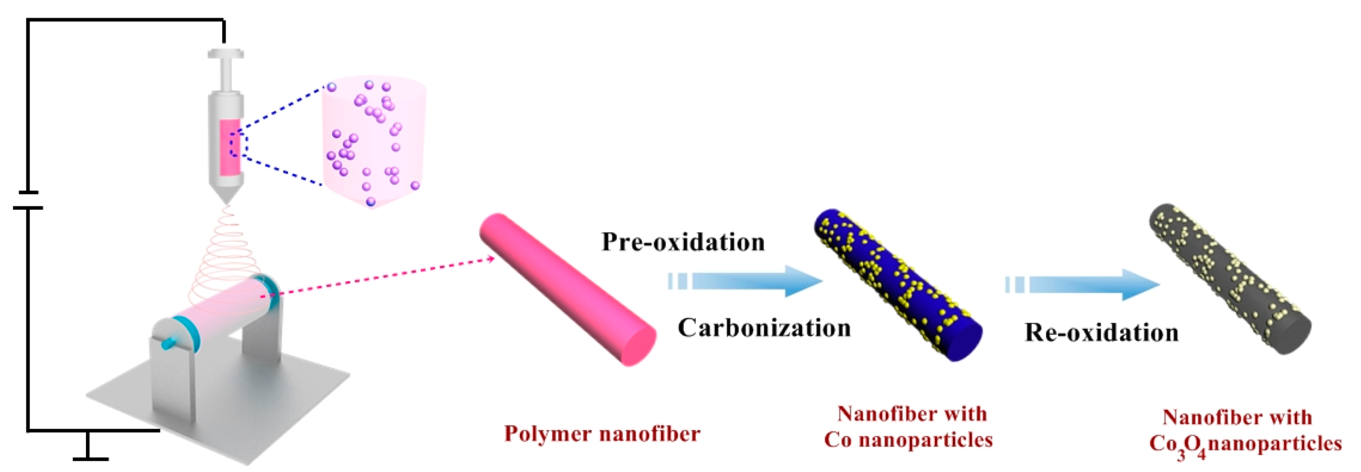
The fabrication process of Co
3O
4@NMCF composite is shown in
Figure 1, which was prepared by electrospinning combined with multi-step heat treatment. After electrospinning, the obtained polymer hybrid nanofibers further underwent pre-oxidation in air to achieve good thermal stabilization. During carbonization in N
2 atmosphere at 800 °C, the Co salt precursor was decomposed and then reduced to metal Co due to the carbothermic reduction. Finally, the metal Co NPs were converted to Co
3O
4 NPs by reoxidation in air, anchored on the N-doped carbon nanofibers. In this work, both PAN and PVP serve as carbon and nitrogen sources. After stirring for a long time, PVP can coordinate with Co
2+ well due to its lactam groups, which is beneficial to form a uniformly PVP/Co(Ac)
2 solution.
Figure S1 illustrates the above mechanism. Benefiting from the different viscosities of the polymers, the PAN, PVP, and Co(Ac)
2 can be separated into PAN (discontinuous phases) and PVP/Co(Ac)
2 (continuous phases) solution. Therefore, the Co
3O
4 NPs can easily and uniformly anchor on the carbon nanofiber after the calcining treatment.
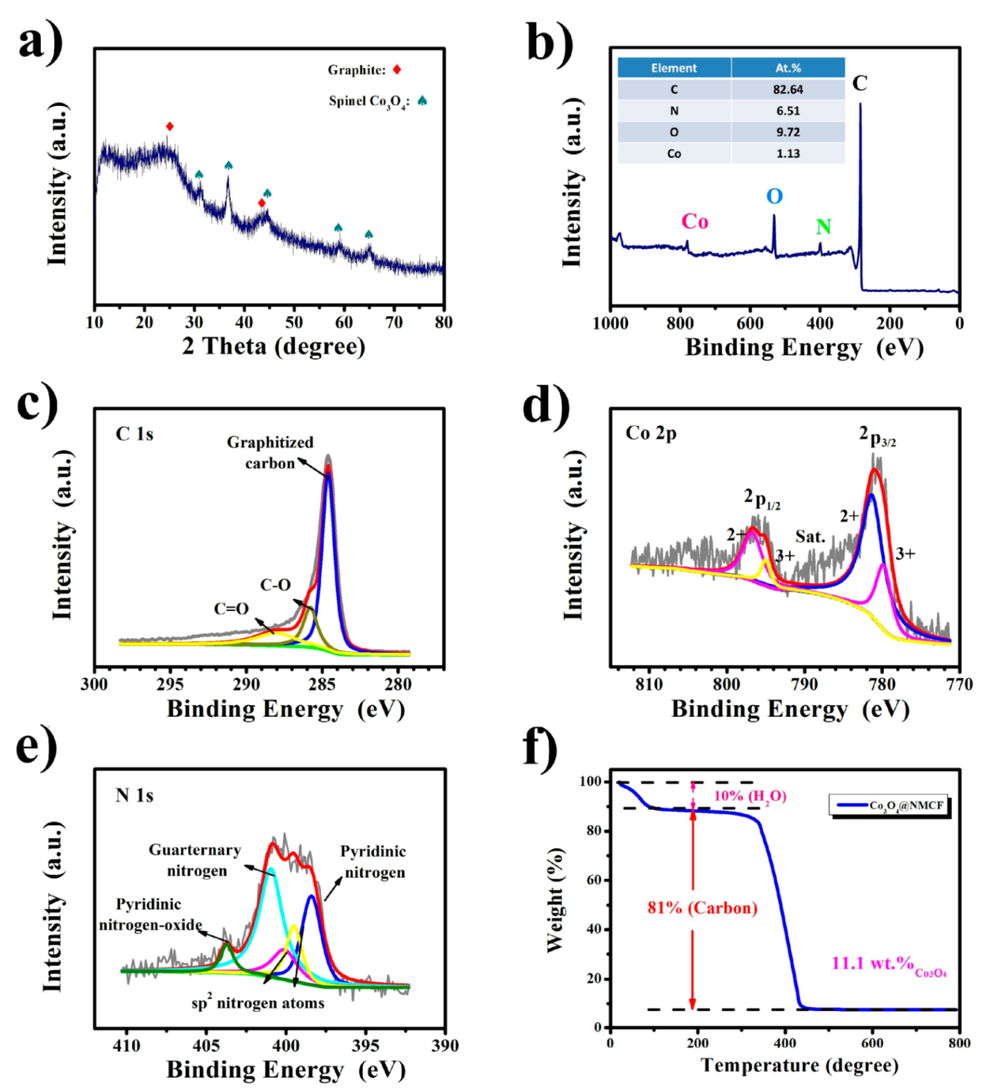
Figure 2a shows the X-ray diffraction (XRD) of Co
3O
4@NMCF composite. All diffraction peaks match well with the spinel structure of Co
3O
4 crystalline (JCPDS card no. 43-1003). As is shown in
Figure 2b, X-ray photoelectron spectrum shows that four elements (Co, O, N, and C) distribute within the Co
3O
4 NP-decorated N-doped mesoporous carbon nanofibers, indicating successful synthesis of the composite. Moreover, it can be found that carbon nanofibers possess a certain extent graphitization, evidenced by an obvious diffraction peak at around 2θ = 26° indexed to the (002) crystallographic plane of carbon. Normally, Raman spectroscopic measurement (
Figure S2) can be used to determine graphitization degree of carbon materials. For the graphitic carbon, its graphitic structure can be reflected by the I
D/I
G ratio, because the number of its defect sites is proportional to the I
D/I
G ratio. So, if the I
D/I
G is higher, the graphitization degree is lower. Based on the Raman results, we found that NMCF shown a certain extent graphitization, evidenced by the relatively low ratio of I
D/I
G (~1.0). This result can be further verified by the C1s spectrum. As shown in
Figure 2c, the deconvoluted four peaks of the C1s spectrum at 284.7, 286.4, and 288.5 eV are associated with the pure graphitic sites; C–O and C=O bond, respectively, of which the pure graphitic sites make up most of the C1s spectrum [
18,
19,
20,
21].
Figure 2d shows the Co2p spectrum, which can further confirm the valence state of elements and detailed composition of Co
3O
4. The Co2p spectrum is well fitted with one shakeup satellite and two spin-orbit doublets, ascribed to Co
2+ and Co
3+ [
11,
12,
22,
23]. More importantly, the two main types of N element are further revealed by the N1s spectrum (
Figure 2e), including quaternary-N and pyridinic-N [
24,
25,
26]. Due to the decomposition of poly(vinylpyrrolidone) (PVP) and polyacrylonitrile (PAN), the N element can be successfully doped into the carbon nanofiber. The nitrogen doping content of NMCF is 6.51 At. %, which is calculated from N1s spectrum. The total mass loading of the Co
3O
4 is ~11.1 wt %, calculated by the TG analysis (
Figure 2f).
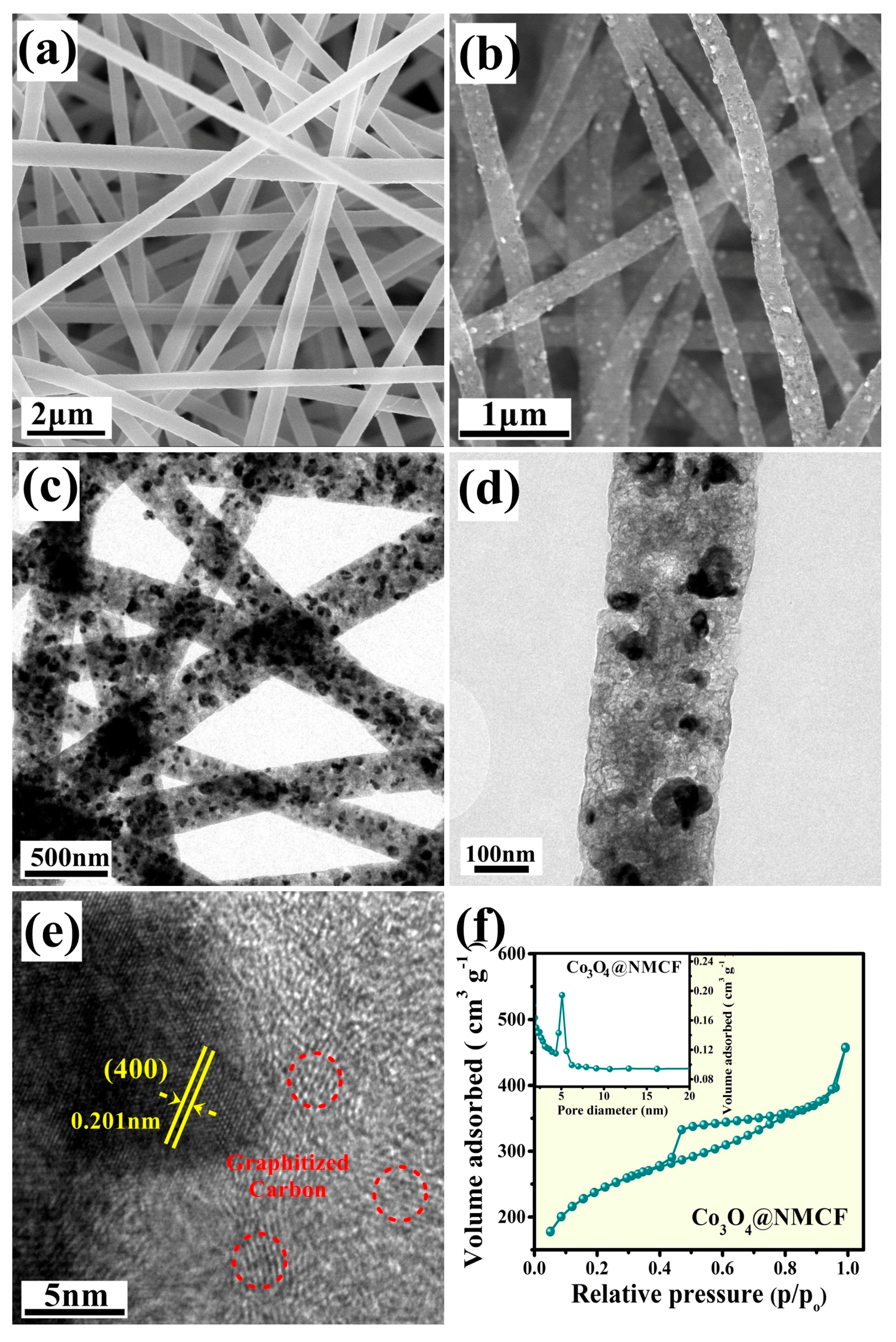
Figure 3a shows the FESEM image of the polymer hybrid nanofibers, which possess the one-dimensional nanofiber structure, uniform diameter (~500 nm) and smooth surfaces. As compared to the precursors, the Co
3O
4@NMCF composite retains the 1D structure but has a smaller diameter (~250 nm) after multi-step heat treatment, shown in
Figure 3b. Furthermore, the numerous Co
3O
4 NPs are uniformly anchored on the nanofiber surface. It can be observed that the particle size of the Co
3O
4 NPs ranges from 20 to 100 nm, evidenced by the TEM and HRTEM images (
Figure 3c,d). Moreover, as shown in
Figure 3e, there is an interplanar spacing (0.201 nm) in the Co
3O
4 NP, corresponding to the spinel (400) plane, which suggests a high crystallinity of Co
3O
4 NPs. In addition, the N
2 adsorption/desorption isotherms of Co
3O
4@NMCF composite and its corresponding pore-size distribution curves are illustrated in
Figure 3f. As shown in
Figure 3f, type-IV curves with an H1-type hysteresis loop are presented in N
2 adsorption/desorption isotherms of the sample, suggesting that Co
3O
4@NMCF composite has a typical mesoporous structure [
27,
28]. The pore-size distribution curves (inset of
Figure 3f) show a narrow pore-size distribution, centered at ~5 nm. Based on the BET methods, the specific surface area the Co
3O
4@NMCF composite are close to 370 m
2 g
−1, and its pore-size is 5.1 nm estimated by BJH model, which further confirm its mesoporous structure.
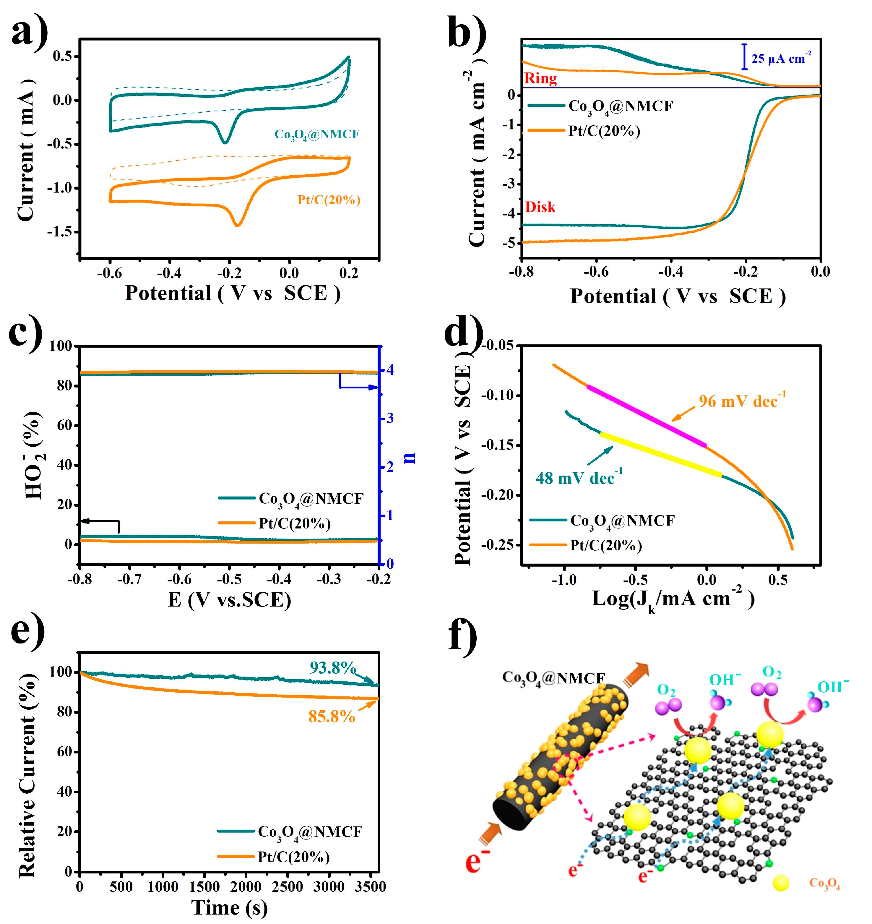
The cyclic voltammetry (CV) curves of Co
3O
4@NMCF and commercial Pt/C (20%) catalysts are shown in
Figure 4a shows, tested in N
2 or O
2-saturated KOH solution (0.1 M). Due to the presence of O
2, the two catalysts all exhibited an obvious cathodic peak, which indicate a substantial ORR process. As observed, the onset potential (E
onset) and reduction peak potential (E
peak) for the ORR of Co
3O
4@NMCF catalyst is similar to that of the commercial Pt/C (20%) catalyst. As shown in
Figure 4b, the linear sweep voltammetry (LSV) curves of Co
3O
4@NMCF catalyst show that its limiting current density (JL) and E
onset are closed to that of the Pt/C (20%) catalyst, suggesting the high ORR catalytic activity of Co
3O
4@NMCF catalyst. In addition, the rotating ring-disk electrode (RRDE) measurements were used to analyze the ORR mechanism of Co
3O
4@NMCF catalyst, conducted in O
2-saturated KOH solution (0.1 M). For the Co
3O
4@NMCF catalyst, its ring current (i
r) (the oxidation of HO
2−) is much smaller than the disk current (i
d) and even negligible, suggesting that the HO
2− evolution is prominently suppressed in the ORR process. Based on the ring and disk current, the HO
2− yield and electron transfer number (
n) of Co
3O
4@NMCF and Pt/C (20%) catalysts can be calculated, shown in
Figure 4c. Over the scanning potential range, the HO
2− yield of Co
3O
4@NMCF catalyst is below 7%, and its corresponding
n is almost constant and close to 4 from −0.2 to −0.8 V during the reaction. Compared with the RRDE results of Pt/C (20%), the low HO
2− yield and high
n indicate a near four electron reaction dominant pathway. Moreover, Tafel plots of Co
3O
4@NMCF and Pt/C (20%) catalysts derived from the LSV curves (
Figure 4b) were shown in
Figure 4d, which can further examine their ORR kinetics. The Tafel slope of Co
3O
4@NMCF catalyst (48 mV dec
−1) at low potentials is smaller than that of Pt/C (20%) (96 mV dec
−1), suggesting the first electron transfer of the rate determining step. The chronoamperometric measurement was performed at −0.3 V (vs. SCE) to evaluate the durability of the ORR catalytic activity for the two catalysts. It can be seen in
Figure 4e, after 3600 s of testing, that the initial activity of Co
3O
4@NMCF catalyst decreases only 6.2%, while Pt/C (20%) catalyst shows the increased initial activity decay (14.2%), indicating that Co
3O
4@NMCF catalyst possesses much higher stability. In order to evaluate the role of Co
3O
4 NPs in ORR, we also have prepared NMCF sample without Co
3O
4, which can be confirmed by the TEM images (
Figure S3a,b) in and XRD (
Figure S3c). Based on the result of LSV test (
Figure S3d), Co
3O
4@NMCF catalyst shows the much better ORR catalytic activity than NMCF catalyst in alkaline conditions, indicating that the Co
3O
4 NPs plays much significant role in ORR. The above results indicate that Co
3O
4@NMCF catalyst shows the high ORR catalytic activity and the remarkable stability, which can be served as a highly efficient ORR electrocatalyst. The superior ORR catalytic activity of the Co
3O
4@NMCF catalyst mainly benefits from the material and structural advantages.
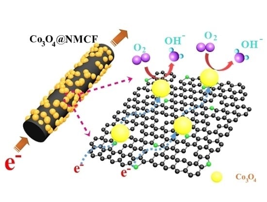
Figure 4f shows the ORR catalytic mechanism of the Co
3O
4@NMCF catalyst. The Co
3O
4 NPs have the high ORR catalytic activity, uniformly anchored on the N-doped carbon nanofibers, which can provide a lot of catalytic active sites for ORR due to the efficient contact with O
2 and electrolyte. Moreover, the 1D carbon nanofibers directly serve as a conductive channel to ensure the fast electron transport. Furthermore, the mesoporous structure of carbon nanofibers is not only beneficial for obtaining high specific surface area, but also can facilitate O
2 diffusion and electrolyte infiltration. In addition, the carbon nanofiber has high N element content existed in the quaternary-N and pyridinic-N types. The doped N element in the carbon frameworks can cause the unique electronic properties due to the synergistic effect between N atom (lone electron pairs) and the graphite (π-conjugated system). As an n-type dopant, the N atom doped into graphitized carbon can increase electric charge density, which is conducive to ORR process, thus improving the ORR catalytic activity. Due to the above-mentioned advantages of the Co
3O
4@NMCF composite architecture, the Co
3O
4@NMCF cathode achieved a remarkable electrocatalytic performance for ORR.
3. Materials and Methods
3.1. Fabrication of Co3O4 NP-Decorated N-Doped Mesoporous Carbon Nanofibers
The Co3O4 NP-decorated N-doped mesoporous carbon nanofibers (Co3O4@NMCFs) were synthesized by using an electrospinning technique combined with the subsequent multi-step heat treatments. Typically, the cobalt acetylacetonate (Co(acac)2) (0.2 g) and PVP (0.5 g) were dissolved into the N,N-dimethylformamide (DMF) (5 mL) under vigorous stirring (50 °C, 2 h) to obtain the PVP solution. For PAN solution, the same as PVP solution, the PAN (0.5 g) was dissolved into DMF (5 mL) and then followed by vigorous stirring (80 °C, 1 h). Then, the above two solutions were mixed with vigorous stirring at 80 °C. The resultant hybrid solution was loaded into a syringe with a single needle of the diameter 0.5 mm. In this experiment, the distance between the collector (aluminum foil) and needle (12 cm), applied voltage (12 kV) and flow rate (0.1 mm min−1) were adopted in the electrospinning process. After drying in the vacuum oven (70 °C, 24 h), the as-electrospun polymer film was used to heat for multi-step procedure. Details are as follows: the dried polymer film was firstly heated in air (250 °C, 1.5 h, air), then heated in N2 (350 °C, 5 h, N2), further heated (800 °C, 1 h, N2), and finally annealed (300 °C, 20 min, air) by using the heating rates of 5 and 1 °C min−1 in air and N2, respectively. The as-prepared Co3O4 NP-decorated N-doped carbon nanofibers film was denoted as Co3O4@NMCF.
3.2. Material Characterizations
For the samples, their crystal structure was investigated by X-ray diffraction (XRD) (D8 Advance, Bruker Company, Karlsruhe, Germany). X-ray photoelectron spectroscopy (XPS) analysis (PHI 5000 VersaProbe, Ulvac-Phi Company, Kanagawa, Japan) was used to characterize the chemical compositions. Thermogravimetric/Differential thermal analysis (TG/DTA) (TGA 7, Perkin Elmer Company, Waltham, MA, USA) was used to calculate the weight retention of Co3O4. The morphology and microstructures were observed by field-emission scanning electron microscope (FE-SEM) (S-4800, Hitachi Company, Tokyo, Japan), transmission electron microscopy (TEM) (Tecnai-20, FEI Company, Hillsboro, OR, USA) and high-resolution transmission electron microscopy (HR-TEM) (JEM-2100, JEOL Company, Tokyo, Japan), respectively. The Brunauer–Emmett–Teller (BET) method was used to analyze the surface area analysis tested on Micromeritics ASAP 2010 (Micromeritics ASAP 2010, Norcross Company, Norcross, GA, USA).
3.3. Electrochemical Measurement
The Co3O4@NMCF and commercial Pt/C (20%) catalyst electrodes with a thin-film (0.1256 cm2) was prepared by dropwise loading the catalyst ethanol suspension (5 mg of Co3O4@NMCF or commercial Pt/C (20%) catalyst, 50 μL of Nafion ethanol solution (5 wt %) and 1 mL of ethanol) on the GC electrode (4 mm in diameter) and then drying. The as-prepared catalyst loading was 625 µg cm−2, and the commercial Pt/C (20%) was tested with Pt loading of 25 µg cm−2. The electrochemical measurements were tested by using an electrochemical workstation (CH Instruments 660C, Chenhua Company, Shanghai, China), including cyclic voltammetry (CV) and rotating ring-disk electrode (RRDE). For RRDE electrode, its collection efficiency is 37%, the inner and outer diameters of ring electrode (GC) are 6.92 and 7.92 mm, and the diameter of disk electrode (Pt) is 5.61 mm. A typical three-electrode system was adopted, consisted of the Co3O4@NMCF catalyst electrode (working electrode), saturated calomel electrode (SCE) (reference electrode), and Pt foil electrode (counter electrode), respectively. The scan rates of RDE and CV experiments were 5 and 20 mV s−1, respectively, tested in the O2-saturated KOH solution (0.1 M).