Article

Catalytic Ammonia Decomposition over High-Performance Ru/Graphene Nanocomposites for Efficient COx-Free Hydrogen Production

1
School of Light Industry and Engineering, South China University of Technology, 381 Wushan Road, Guangzhou 510641, China
2
Department of Chemical Engineering, Hiroshima University, 1-4-1 Kagamiyama, Higashi-Hiroshima 739-8527, Japan
*
Author to whom correspondence should be addressed.
Catalysts 2017, 7(1), 23; https://doi.org/10.3390/catal7010023
Submission received: 22 November 2016 / Revised: 19 December 2016 / Accepted: 5 January 2017 / Published: 11 January 2017
(This article belongs to the Special Issue Ruthenium Catalysts)

Abstract

:
Highly-dispersed Ru nanoparticles were grown on graphene nanosheets by simultaneously reducing graphene oxide and Ru ions using ethylene glycol (EG), and the resultant Ru/graphene nanocomposites were applied as a catalyst to ammonia decomposition for COx-free hydrogen production. Tuning the microstructures of Ru/graphene nanocomposites was easily accomplished in terms of Ru particle size, morphology, and loading by adjusting the preparation conditions. This was the key to excellent catalytic activity, because ammonia decomposition over Ru catalysts is structure-sensitive. Our results demonstrated that Ru/graphene prepared using water as a co-solvent greatly enhanced the catalytic performance for ammonia decomposition, due to the significantly improved nano architectures of the composites. The long-term stability of Ru/graphene catalysts was evaluated for COx-free hydrogen production from ammonia at high temperatures, and the structural evolution of the catalysts was investigated during the catalytic reactions. Although there were no obvious changes in the catalytic activities at 450 °C over a duration of 80 h, an aggregation of the Ru nanoparticles was still observed in the nanocomposites, which was ascribed mainly to a sintering effect. However, the performance of the Ru/graphene catalyst was decreased gradually at 500 °C within 20 h, which was ascribed mainly to both the effect of the methanation of the graphene nanosheet under a H2 atmosphere and to enhanced sintering under high temperatures.

Graphical Abstract

1. Introduction

To realize the use of hydrogen as a primary energy source instead of fossil fuels in the future, tremendous effort has been dedicated to important issues such as hydrogen production, storage, and utilization. Among these issues, hydrogen storage seems to be the most intractable to the potential hydrogen economy, because the volumetric density of hydrogen is extremely low and is far from the target value for practical application. Various strategies [1,2,3,4] have been proposed for hydrogen storage in an attempt to improve its volumetric density, which can be mainly categorized by either physical or chemical storage routes. In physical storage routes, hydrogen compressed under high pressure or stored in a liquid state can achieve attractive volumetric density, but these technologies suffer from extremely harsh processing conditions at a very high cost with severe safety concerns. On the other hand, although hydrogen can be stored in porous materials via adsorption under mild conditions [5,6,7,8,9], the relatively low hydrogen storage capacity of various sorbents seems to be an insurmountable obstacle for practical applications. A great deal of attention has been paid to the chemical storage of hydrogen, and various types of hydrogen storage systems have been intensively studied based on different hydrogen carriers such as metal and organic hydrides [10,11,12,13,14]. Ammonia [15,16,17,18,19,20] has recently been widely accepted as a very promising and important hydrogen carrier owing to its fascinating properties. First, ammonia has a very high mass storage capacity (17.6 wt %) and can be easily stored as a liquid under mild conditions that equate to an extremely high volumetric hydrogen storage density of 108 g/L, which is much higher than that of liquid hydrogen (71 g/L) [16]. Furthermore, as one of the most important bulk chemicals, the ammonia industry has operated worldwide for almost a century in terms of synthesis technology, as well as storage and transportation infrastructure, which significantly facilitates ammonia as an ideal hydrogen carrier for large-scale applications. It is important to note that by comparison with traditional carbonaceous compounds, hydrogen produced via ammonia decomposition is COx-free, which means the ammonia decomposition process is free of CO2 emissions, and the produced hydrogen can be easily used for proton-exchange membrane fuel-cell applications without CO poisoning.
Using ammonia as a hydrogen carrier is a feasible solution to the hydrogen storage issue, but eventually the ammonia must be efficiently decomposed, and this is particularly important for the on-site generation of a hydrogen stream for mobile applications, such as in fuel-cell electrical vehicles. In this regard, the development of high-performance ammonia decomposition catalysts would be of significant importance for an ammonia-mediated hydrogen economy. Although research effort focused on the catalysis of ammonia decomposition has increased rapidly in recent years [21,22,23,24,25,26,27,28,29,30], and the catalytic activity of current catalysts still requires significant improvement because the current level of ammonia conversion remains much lower than the equilibrium, particularly at reaction temperatures lower than 400 °C. Research progress has identified that Ru is currently the most active component for ammonia decomposition. The control of Ru particles with optimal size and morphology is very important in ammonia decomposition since ammonia decomposition with Ru is structure-sensitive due to the variation of highly active B5-type sites [31,32]. These sites arrange three Ru atoms in one layer with two more in the layer directly above, which amounts to a monoatomic step on a Ru (0001) terrace for different structures [33,34]. Moreover, the catalytic activity of Ru is support-dependent [35,36,37]. Generally, a support that facilitates the transfer of electrons to Ru is beneficial to the catalytic activity of the Ru catalysts, which is helpful to the recombination desorption of N atoms from the Ru surface [35], and this is the rate-determining step for ammonia decomposition. Therefore, conductive carbon materials, such as carbon nanotubes (CNTs) [36,37,38], have been intensively studied as effective supports for ammonia decomposition. Very recently, novel graphene sheets with excellent conductivity, an extremely high proportion of specific surface area, and an inorganic electrode of C12A7:e that enables electron injection to the antibonding orbital of the Ru–N bond have been proposed as a high-performance support [21,39].
Considering the importance of both the support properties and the tuning of Ru microstructures for the development of high-performance ammonia decomposition catalysts, we previously proposed a novel Ru/graphene nanocomposite with an easily controlled nano architecture for use as a high-performance ammonia decomposition catalyst for efficient COx-free hydrogen production [39]. Additional study is needed regarding the catalytic behavior of Ru/graphene nanocomposites. In the present study, Ru/graphene nanocomposites with well-controlled Ru loading and structures were prepared in an effort to further tune their catalytic performance, and the mechanisms responsible for the stability of these catalysts during ammonia decomposition and deactivation under high temperatures were discussed.

2. Results and Discussion

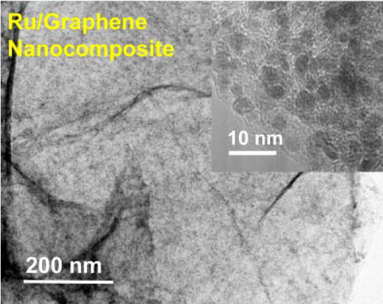
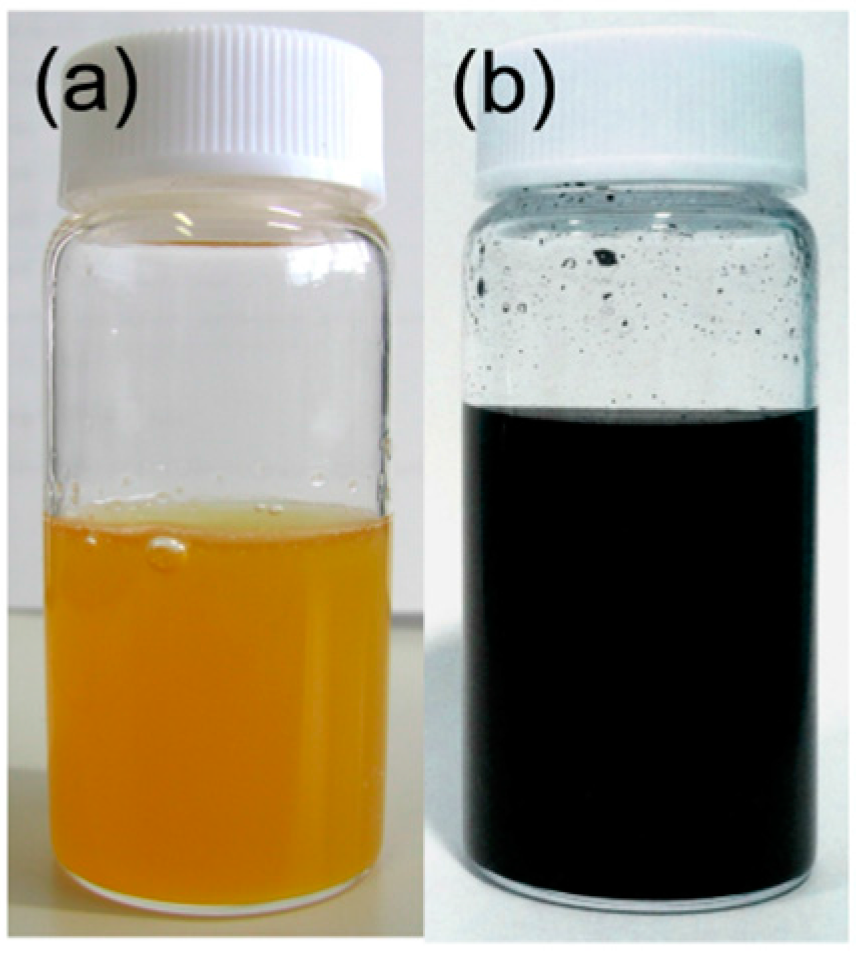
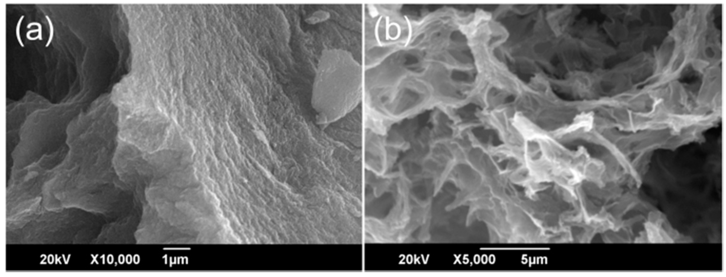
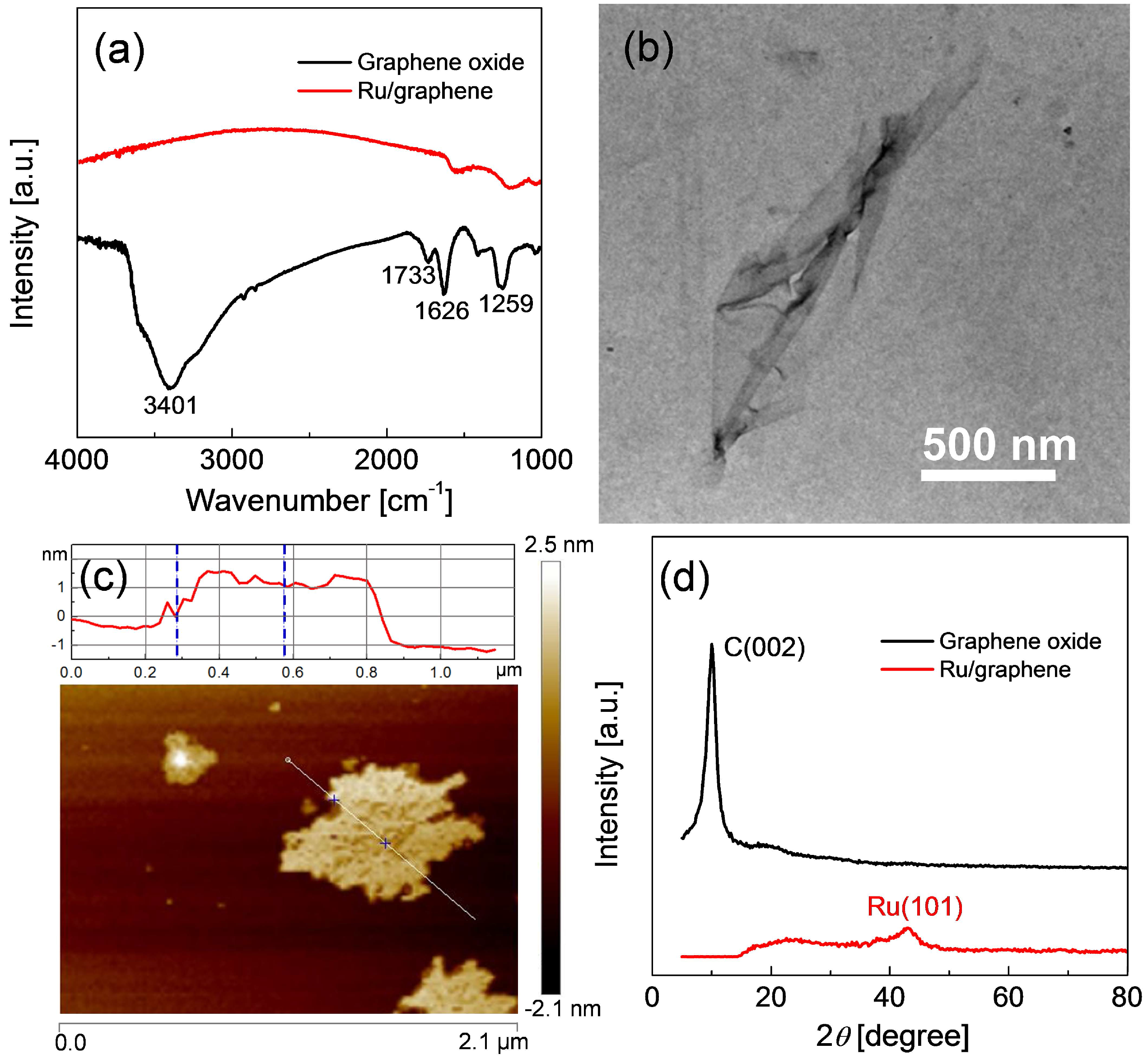
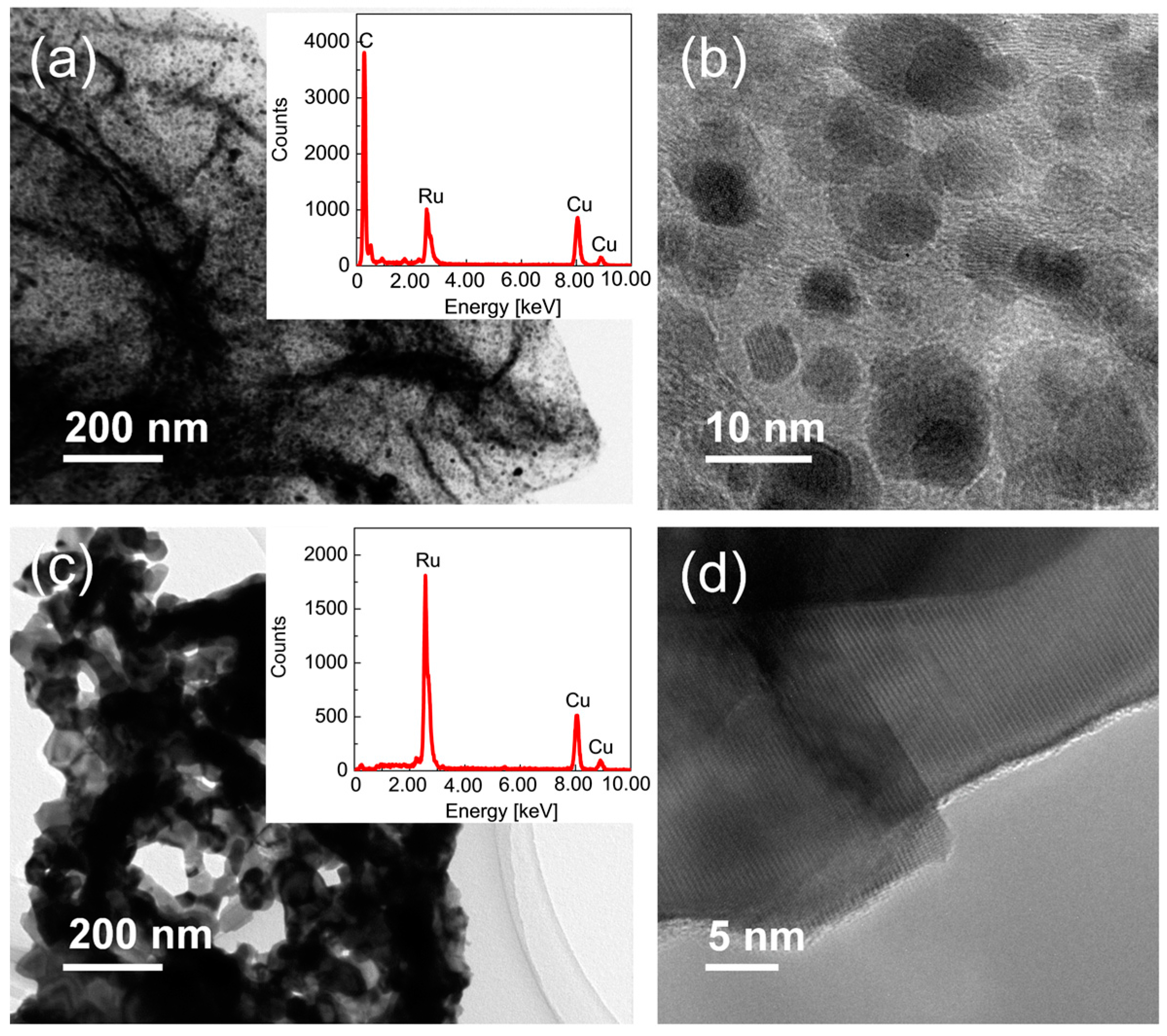
2.1. Preparation of Ru/Graphene Nanocomposites

Figure 1 shows the photographs of pristine graphene oxide and a Ru/graphene nanocomposite. After oxidation in a mixture of concentrated H2SO4 and KMnO4, followed by treatment with H2O2, the graphite flakes were transformed to a soluble yellow slurry (Figure 1a), which is an indicator of the efficient oxidation of graphite. As confirmed by Fourier transform infrared spectroscopy (FT-IR) spectra (Figure 2a), the notable adsorption peaks centered at wavenumbers 3401, 1733, 1626, and 1259 cm−1 corresponded to O–H, C=O, C=C, and C–O–C vibrations, respectively, which indicated that the graphene oxide had a considerable level of oxygen-containing functional groups. The transmission electron microscope (TEM) image in Figure 2b shows the sheet-like morphology of the prepared graphene oxide, which demonstrated that the layered graphite was successfully exfoliated into nanosheets after the oxidation process. The height profile of an atomic force microscope (AFM) image (Figure 2c) further confirmed that the graphene oxide naonosheet was ~1.2 nm in thickness, which corresponded to the single-layer graphene oxide sheet. After reducing the graphene oxide and RuCl3 using EG at high temperatures, a black Ru/graphene solid was finally obtained (Figure 1b). The Fourier transform infrared spectroscopy (FT-IR) spectra in Figure 2a confirmed that the Ru/graphene showed a much reduced level of oxygen-containing functional groups, suggesting the efficient reduction of graphene oxide to graphene. Figure 2d shows the powder X-ray diffraction (PXRD) diffraction patterns of graphene oxide and Ru/graphene. After the reduction process, the diffraction peak at 2θ = 10.3° for graphene oxide disappeared in the resultant Ru/graphene composite, because of the loss of the regular stacking of the original sheets. A new and broad diffraction peak at 2θ = 43.0° was observed, which corresponded to the (101) crystallographic planes of nanosized metallic Ru particles, and this indicated that Ru nanoparticles were successfully deposited onto the graphene sheets. Therefore, simultaneously reducing Ru3+ ions and graphene oxide via a polyol route using EG is very simple and effective when preparing Ru/graphene nanocomposites.
It is should be noted that the final drying process is a key step to successfully obtain high-quality Ru/graphene nanocomposites. Figure 3 shows the scanning electron microscope (SEM) images of Ru/graphene nanocomposites prepared by drying under air and by freeze-drying. With evaporation of water by drying under air at room temperature, the Ru/graphene composite gradually contracted and eventually formed an extremely dense structure (Figure 3a). On the contrary, when the Ru/graphene was prepared via freeze-drying, the bulk materials were frozen and then became very rigid, which efficiently prevented the Ru/graphene nanocomposite from contracting during the drying process and, thus, highly porous three-dimensional networks were finally formed (Figure 3b). For catalytic applications, the highly porous structure of a Ru/graphene nanocomposite provided a much larger proportion of Ru surface area, which significantly reduced the diffusion resistance and increased the number of active sites in the catalyst during the reactions. Therefore, the highly porous Ru/graphene nanocomposite is much more superior to the dense version as a catalyst for ammonia decomposition.

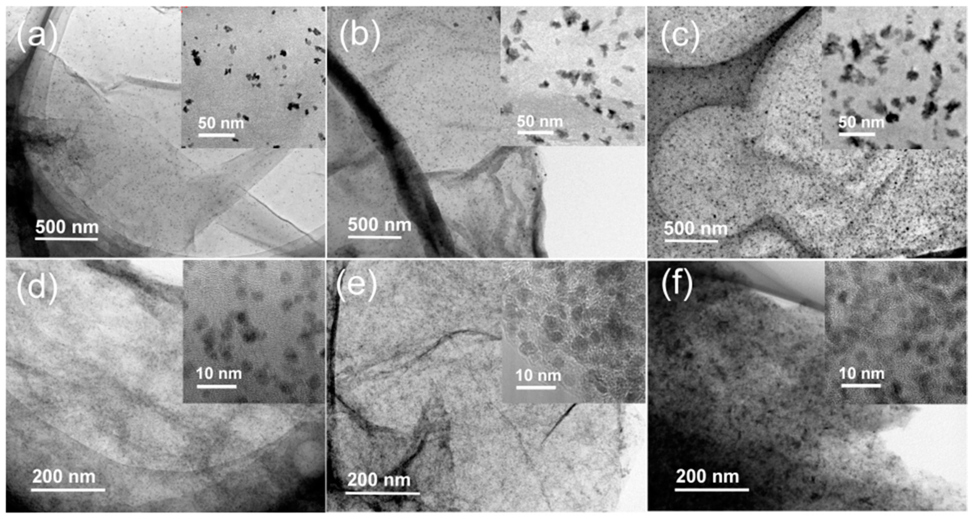
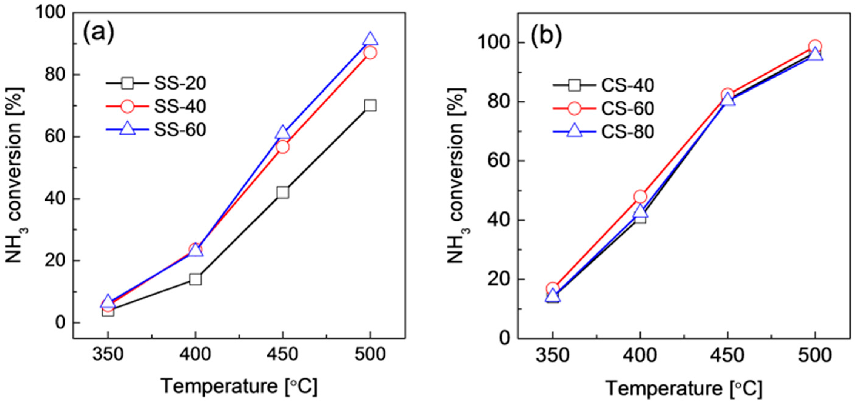
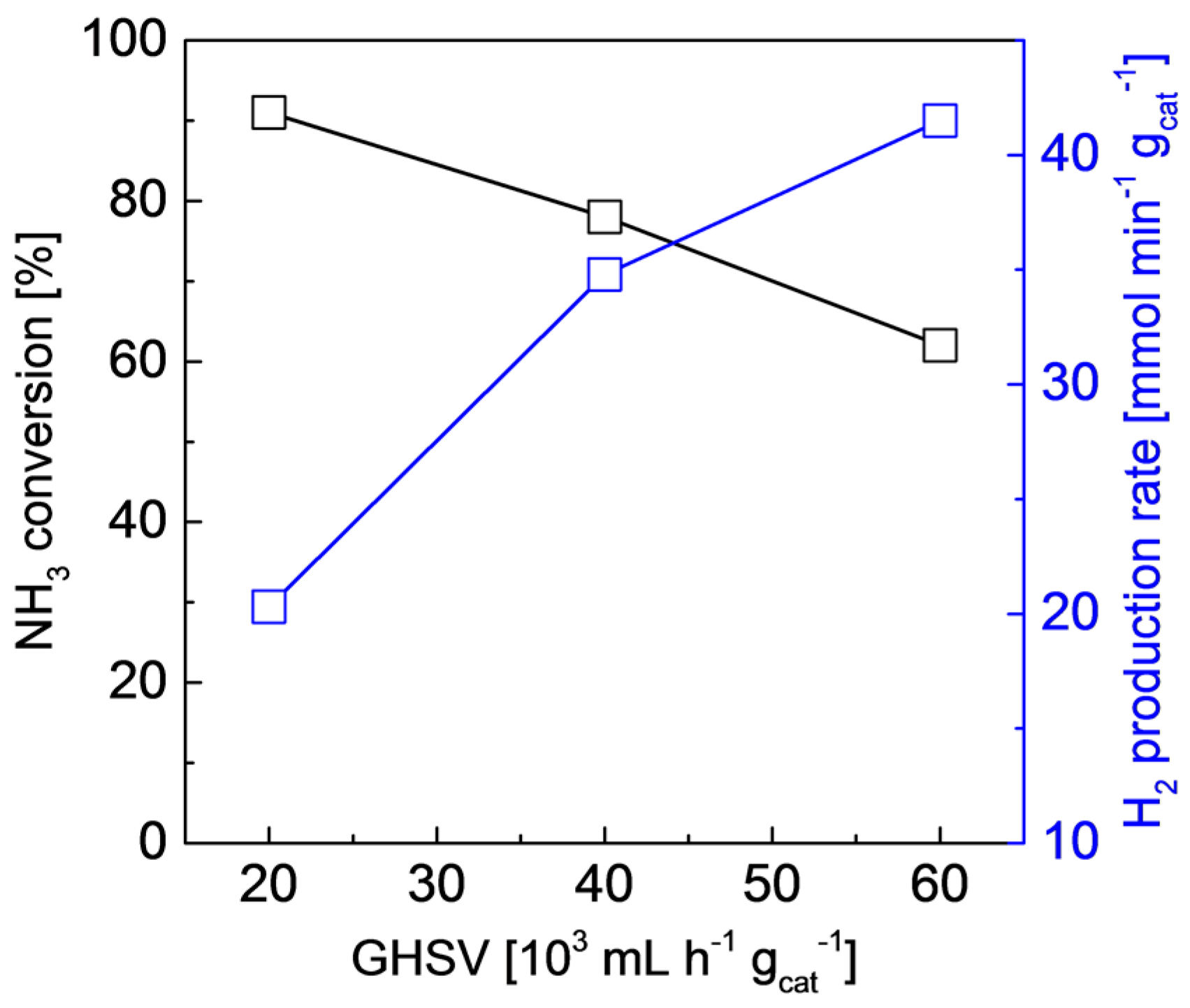
2.2. Structures and Catalytic Activities of Ru/Graphene Nanocomposites for Ammonia Decomposition

Figure 4 shows the TEM images of Ru/graphene nanocomposites with different levels of Ru loading. For the Ru/graphene prepared in EG single solvent (SS) and water-EG co-solvent (CS) systems with M g RuCl3 in the precursor solution, the samples were denoted as SS-M and CS-M, respectively. For Ru/graphene nanocomposites prepared in the SS system, the SS-20, SS-40, and SS-60 Ru/graphene nanocomposites showed a homogeneous dispersion of irregular-shaped Ru nanoparticles onto the graphene sheets, with increased Ru average particle sizes of ~10, 22, and 35 nm and Ru loadings of 18, 33, and 45 wt %, respectively. However, when the Ru/graphene nanocomposites were fabricated in the CS system, the CS-40, CS-60 and CS-80 Ru/graphene nanocomposites showed a much more uniform dispersion of round-shaped Ru nanoparticles on the graphene sheets, with increased Ru loadings of 32, 42, and 54 wt %. Further increasing the RuCl3 amount in the precursor solution did not result in higher Ru loading, since almost the entire graphene surface was covered by the nanosized Ru particles. It should be noted that all the Ru/graphene nanocomposites prepared in the CS system showed the same Ru average particle size, ~4 nm, and Ru morphology on the graphene, regardless of the RuCl3 amount added to the precursor solution. Obviously, by adjusting the RuCl3 amount in the precursor solution, both the SS and CS systems allowed a facile tuning of the Ru loading over a very wide range. The high Ru loading capacity could be mainly ascribed to the presence of a considerable amount of oxygen-containing groups on the graphene oxide, which acted as nucleation and anchoring sites for the growth of Ru nanoparticles. Furthermore, both the Ru particle size and morphology were significantly affected by the presence of water as a co-solvent in the precursor solution, and the CS system showed Ru nanoparticles that were much smaller and more uniform, resulting in an excellent Ru dispersion on the graphene nanosheets. Compared with the other recently reported metal particle/graphene composites, the Ru/graphene composites prepared in the present work also showed much smaller and more uniform metallic particles [7,8], indicating the formation of high-quality Ru/graphene composites. Due to the structure-sensitive feature of ammonia decomposition on Ru [31,32], the Ru/graphene prepared from the CS system simultaneously allowed good control of the Ru particle size and shape on graphene nanosheets even at extremely high levels of Ru loading (>50 wt %), which was favorable for highly enhanced catalytic activity for ammonia decomposition.
Carbon nanotubes (CNTs) were thought to provide very efficient support for ammonia decomposition [35,36,37,38] because of their high surface area and excellent electronic conductive properties. To further study the effect of graphene oxide on the microstructure of Ru catalysts, a Ru/CNT composite was prepared in the CS system with the same Ru loading of CS-60 Ru/graphene, and these were compared. Figure 5 shows the TEM image of a Ru/CNT nanocomposite. In addition to a considerable amount of very small Ru particles distributed onto the CNTs, many large (~40 nm) Ru particles with a round shape were formed by the aggregation of fine Ru nanoparticles. The large Ru aggregates were ascribed mainly to a loading capacity of CNTs that was lower than that of graphene, because the surface of CNTs has considerably fewer oxygen-containing groups to act as anchoring sites for Ru deposition. This makes the immobilization of a considerable amount of Ru nanoparticles more difficult on CNTs than on graphene, particularly for extremely high levels of Ru loading. Although both graphene and CNTs are interesting carbon materials with a high surface area for catalyst support applications, graphene seems to be much more advantageous for Ru deposition in terms of exceptional Ru dispersion and a high capacity for Ru loading.
Figure 6 shows the catalytic performance of Ru/graphene nanocomposites with different levels of Ru loading for ammonia decomposition under a GHSV of 20,000 mL·h−1·gcat−1. All catalysts showed rapidly improved ammonia conversion with increasing temperature, due to the highly enhanced ammonia decomposition rate at high temperatures. With increasing Ru loading, SS-40 Ru/graphene nanocomposites showed ammonia conversion that was obviously improved compared with that of SS-20, while the further Ru increase in the SS-60 showed catalytic performance that was similar to that of SS-40. On the other hand, CS-40, CS-60, and CS-80 Ru/graphene nanocomposites showed almost the same catalytic performance, although the variation in Ru loading in the nanocomposites occurred over a wide range, the Ru particle size and shape were the same. However, with comparable, or even much lower, levels of Ru loading, the Ru/graphene nanocomposites prepared in a CS system showed much better catalytic performance than those prepared in a SS system, which was attributed mainly to the improved Ru dispersions as well as to the optimal Ru microstructures, since the ammonia decomposition on Ru is structure-sensitive [31,32]. Figure 7 shows the catalytic performance of CS-60 Ru/graphene at 450 °C under different GHSVs. As the GHSV increased from 20,000 to 60,000 mL·h−1·gcat−1, ammonia conversion gradually decreased from 91% to 62% with a corresponding hydrogen production rate that increased from 20.3 to 41.5 mmol·min−1·gcat−1. However, the Ru/CNT catalyst reportedly showed ammonia conversions lower than 50% at 450 °C under a GHSV of 30,000 mL·h−1·gcat−1 [36,37]. In addition, compared with most of the other reported ammonia decomposition catalysts under similar reaction conditions [22,23,24,25,26], this CS-60 Ru/graphene also showed very attractive catalytic performance for COx-free hydrogen production from ammonia, which indicated that graphene nanosheets supporting Ru nanoparticles is a very productive ammonia decomposition catalyst for practical applications.

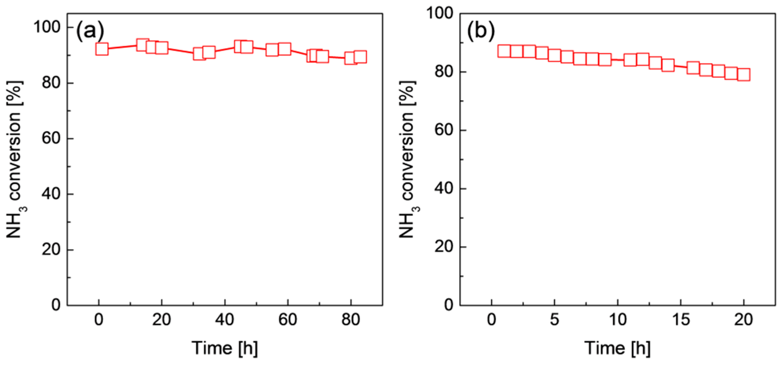
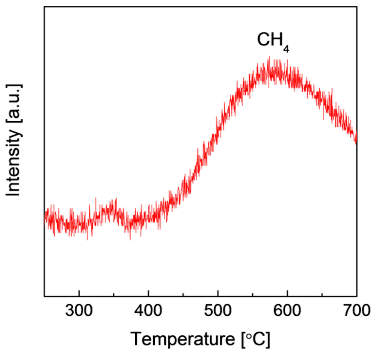
2.3. Stability of Ru/Graphene Nanocomposites for Hydrogen Production from Ammonia

To provide high-purity hydrogen for practical applications, such as proton exchange membrane fuel cell applications, it is preferable that the ammonia is completely decomposed, because even the presence of a trace amount of ammonia in hydrogen may poison the electrodes of a fuel cell. A high reaction temperature is favorable for a high degree of ammonia decomposition, and, thus, the high-temperature catalytic stability of Ru/graphene nanocomposites is very important for practical hydrogen production from ammonia. Figure 8 shows the time course of CS-60 and SS-40 Ru/graphene nanocomposites for ammonia decomposition at 450 and 500 °C, respectively. For CS-60 Ru/graphene, ammonia conversion was kept almost constant within a test time of 80 h, showing excellent catalytic stability at 450 °C. However, with ammonia decomposition over SS-40 Ru/graphene at 500 °C, the ammonia conversion gradually decreased with increasing reaction time, which indicated that deactivation had occurred for the catalyst at 500 °C. Figure 9 shows the TEM images of CS-60 and SS-40 Ru/graphene nanocomposites after catalytic ammonia decomposition at 450 and 500 °C for 80 and 20 h, respectively. In contrast to as-prepared CS-60 Ru/graphene (Figure 4e), the Ru nanoparticles used in the CS-60 were extensively aggregated, which resulted in a considerable amount of particles larger than 10 nm (Figure 9a,b), although the catalytic performance seemed to remain good. The energy dispersive X-ray spectroscopy (EDX) examination (inset in Figure 9a) showed that there were no significant changes in the composition of the catalyst. We believed that the structure change of CS-60 Ru/graphene could be ascribed mainly to the sintering effects at high temperatures. For SS-40 Ru/graphene nanocomposites, the TEM images in Figure 9c,d show that the Ru nanoparticles reached the micro scale, even though the reaction was performed at 500 °C for only 20 h. Obviously, the aggregation of Ru particles when SS-40 Ru/graphene was used was even worse. Surprisingly, further EDX analysis (inset in Figure 9c) of the use of SS-40 Ru/graphene revealed that the amount of C content decreased significantly in the nanocomposites, which indicated that most of the graphene might have been degraded under these reaction conditions. It was evident that the sintering on the Ru particles in the composites would be significantly enhanced without the anchoring of the graphene supports, which could have been the main reason for the extremely large Ru particles when SS-40 composites were used, as well as for the obvious decrease in catalytic performance at 500 °C.
To gain further insight into the deactivation mechanism at high temperatures, the Ru/graphene nanocomposite was treated in a H2/Ar flow (V/V = 1/9) of 40 mL·min−1 from 250 to 700 °C at a heating rate of 10 °C/min, and the outlet gas composition was analyzed using a mass spectrometer. Figure 10 shows the mass spectrum of Ru/graphene treated under a H2 atmosphere at different temperatures. A CH4 peak was observed when the temperature was higher than 420 °C, which indicated the formation of methane at high temperatures. The generation of CH4 was very remarkable when the temperature was higher than 450 °C, and this agreed well with the obviously degraded ammonia decomposition performance for SS-40 nanocomposites at 500 °C. The formation of CH4 resulted from the methanation of graphene sheets in a hydrogen atmosphere at high temperatures, and this phenomenon is commonly observed for carbon materials with exposure to hydrogen at high temperatures [38,40,41]. Therefore, the deactivation of Ru/graphene catalysts at high temperatures could be mainly ascribed to both sintering and methanation. Stable hydrogen production for practical applications still requires additional effort to further optimize the nanostructure of Ru/graphene composites for improved catalytic stability and activity at relatively low temperatures.

3. Materials and Methods

3.1. Materials

Natural graphite flakes (>99.8%, 325 mesh) were supplied by Alfa Aesar (Haverhill, MA, USA). RuCl3·nH2O and ethylene glycol were purchased from Wako Pure Chemical Industrials, Ltd., Tokyo, Japan. KMnO4, concentrated H2SO4 (98 wt %), and H2O2 were obtained from Sigma-Aldrich (Tokyo, Japan).

3.2. Preparation and Characterization of Ru/Graphene Nanocomposites

Graphene oxide was prepared according to a previously reported procedure [39]. Ru/graphene nanocomposites were prepared by simultaneously reducing graphene oxide and RuCl3 using ethylene glycol (EG) as a reducing agent. Briefly, 20–80 mg graphene oxide was dissolved either in 100 mL EG single solvent (SS) or 100 mL water-EG co-solvent (CS) (V/V = 1/1) under magnetic stirring, and the mixture was then sonicated for 30 min to ensure a homogeneous dispersion. Subsequently, this homogeneous solution was added into a 150 mL Teflon-lined stainless autoclave, and was then transferred into an oven for 3 h at a pre-heated temperature of 200 °C. After the reduction process, black solid products were collected via filtration, and were then washed three times with water. Finally, the black solid was freeze-dried to obtain Ru/graphene nanocomposites.
FT-IR spectra were measured on a FT/IR-4100 spectrophotometer (Jasco, Tokyo, Japan) using samples deposited onto a KBr plate. PXRD patterns were carried out using a D/Max-2500 X-ray diffractometer (Rigaku, Tokyo, Japan) with Cu Kα radiation (λ = 1.54056 Å) at a scan rate of 0.05° s−1. AFM observations were performed on a Nanocute scanning probe microscope (SII Nanotechnology Inc., Tokyo, Japan) operated under a tapping model. SEM images were obtained on a JCM-5700 SEM (JEOL, Tokyo, Japan) using an acceleration voltage of 20 kV. TEM images and EDX spectra were collected using a JEM-2011 TEM (JEOL, Tokyo, Japan) equipped with an energy dispersive X-ray spectrometer operated at an accelerating voltage of 200 kV. Gas components were identified using a BELMass quadrupole mass spectrometer (MicrotracBEL, Osaka, Japan).

3.3. Catalyst Testing

The catalytic activities of Ru/graphene nanocomposites for ammonia decomposition were evaluated in a tubular quartz fixed-bed reactor (inner diameter: 6 mm) under atmospheric pressure and temperatures ranging from 350 °C to 500 °C. Briefly, 50 mg Ru/graphene nanocomposites were loaded inside the quartz tube, with quartz wool packed at both ends of the catalyst bed. Before the catalytic reaction, the reactor was purged with He under a flow rate of 100 mL·min−1 for 30 min to remove air in the system. The reactor was heated to desired temperatures with the catalyst kept under a He atmosphere, then ammonia was fed into the reactor at GHSVs of 20,000–60,000 mL·h−1·gcat−1. Gas compositions of the catalytic products were analyzed online using a GC-14B gas chromatograph (Shimadzu, Kyoto, Japan) equipped with a thermal conductivity detector and a Porapak N column using N2 as a carrier gas.

4. Conclusions

High-quality Ru/graphene nanocomposites were prepared by simultaneously reducing graphene oxide and Ru ions using ethylene glycol for COx-free hydrogen production from ammonia. The assistance of considerable oxygen-containing groups on graphene oxide sheets allowed the homogeneous growth of Ru nanoparticles on graphene nanosheets even with very high levels of Ru loading. Moreover, the addition of water in the precursor solution as a co-solvent during the reduction process further efficiently improved the dispersion as well as the size and morphology of Ru nanoparticles on the graphene nanosheets, which resulted in highly-enhanced catalytic performance for ammonia decomposition. The structural changes that were observed in the Ru/graphene nanocomposites during ammonia decomposition allowed the production of COx-free hydrogen at high temperatures, which was ascribed mainly to the sintering effect and to the methanation of the graphene supports.

Acknowledgments

This work was supported by KAKENHI (Grant Numbers: 15K14207 and 15H02313), and the Fundamental Research Funds for the Central Universities (Grant Number: 2015ZZ136).

Author Contributions

G.L. performed the experiments and wrote the manuscript. M.K. and T.T. provided suggestions and assistance in experiment design and manuscript editing.

Conflicts of Interest

The authors declare no conflict of interest.

References

  1. Murray, L.J.; Dincă, M.; Long, J.R. Hydrogen storage in metal–organic frameworks. Chem. Soc. Rev. 2009, 38, 1294–1314. [Google Scholar] [CrossRef] [PubMed]
  2. Eberle, U.; Felderhoff, M.; Schüth, F. Chemical and Physical Solutions for Hydrogen Storage. Angew. Chem. Int. Ed. 2009, 48, 6608–6630. [Google Scholar] [CrossRef] [PubMed]
  3. Hamilton, C.W.; Baker, R.T.; Staubitz, A.; Manners, I. B–N compounds for chemical hydrogen storage. Chem. Soc. Rev. 2009, 38, 279–293. [Google Scholar] [CrossRef] [PubMed]
  4. Zhu, Q.-L.; Xu, Q. Liquid organic and inorganic chemical hydrides for high-capacity hydrogen storage. Energy Environ. Sci. 2015, 8, 478–512. [Google Scholar] [CrossRef]
  5. Han, S.S.; Furukawa, H.; Yaghi, O.M.; Goddarlll, W.A. Covalent organic frameworks as exceptional hydrogen storage materials. J. Am. Chem. Soc. 2008, 130, 11580–11581. [Google Scholar] [CrossRef] [PubMed]
  6. Yang, S.J.; Kim, T.; Im, J.H.; Kim, Y.S.; Lee, K.; Jung, H.; Rae, C. MOF-derived hierarchically porous carbon with exceptional porosity and hydrogen storage capacity. Chem. Mater. 2012, 24, 464–470. [Google Scholar] [CrossRef]
  7. Zhou, C.; Szpunar, J.A.; Cui, X. Synthesis of Ni/graphene nanocomposite for hydrogen storage. ACS Appl. Mater. Interfaces 2016, 8, 15232–15241. [Google Scholar] [CrossRef] [PubMed]
  8. Zhou, C.; Szpunar, J.A. Hydrogen storage performance in Pd/graphene nanocomposites. ACS Appl. Mater. Interfaces 2016, 8, 25933–25940. [Google Scholar] [CrossRef] [PubMed]
  9. Parambhath, V.B.; Nagar, R.; Ramaprabhu, S. Effect of nitrogen doping on hydrogen storage capacity of palladium decorated graphene. Langmuir 2012, 28, 7826–7833. [Google Scholar] [CrossRef] [PubMed]
  10. Liu, X.; Langmi, H.W.; Beattie, S.D.; Azenwi, F.F.; McGrady, G.S.; Jensen, C.M. Ti-doped LiAlH4 for hydrogen storage: Synthesis, catalyst loading and cycling performance. J. Am. Chem. Soc. 2011, 133, 15593–15597. [Google Scholar] [CrossRef] [PubMed]
  11. Filinchuk, Y.E.; Yvon, K. Boron-induced hydrogen localization in the novel metal hydride LaNi3BHx (x = 2.5–3.0). Inorg. Chem. 2005, 44, 4398–4406. [Google Scholar] [CrossRef] [PubMed]
  12. Alhumaidan, F.; Cresswell, D.; Garforth, A. Hydrogen storage in liquid organic hydrides: Producing hydrogen catalytically for methylcyclohexane. Energy Fuels 2011, 25, 4217–4234. [Google Scholar] [CrossRef]
  13. Li, G.; Yada, K.; Kanezashi, M.; Yoshioka, T.; Tsuru, T. Methylcyclohexane dehydrogenation in catalytic membrane reactors for efficient hydrogen production. Ind. Eng. Chem. Res. 2013, 52, 13325–13332. [Google Scholar] [CrossRef]
  14. Teichmann, D.; Arlt, W.; Wasserscheid, P.; Freymann, R. A future energy supply based on liquid organic hydrogen carriers (LOHC). Energy Environ. Sci. 2011, 4, 2767–2773. [Google Scholar] [CrossRef]
  15. Lan, R.; Irvine, J.T.S.; Tao, S. Ammonia and related chemicals as potential indirect hydrogen materials. Int. J. Hydrog. Energy 2012, 37, 1482–1494. [Google Scholar] [CrossRef]
  16. Klerke, A.; Christensen, C.H.; Nørskov, J.K.; Vegge, T. Ammonia for hydrogen storage: Challenges and opportunities. J. Mater. Chem. 2008, 18, 2304–2310. [Google Scholar] [CrossRef]
  17. Vitse, F.; Cooper, M.; Botte, G.G. On the use of ammonia electrolysis for hydrogen production. J. Power Sources 2005, 142, 18–26. [Google Scholar] [CrossRef]
  18. Christensen, C.H.; Johannessen, T.; Sørensen, R.Z.; Nørskov, J.K. Towards an ammonia-mediated hydrogen economy. Catal. Today 2006, 111, 140–144. [Google Scholar] [CrossRef]
  19. Li, G.; Kanezashi, M.; Yoshioka, T.; Tsuru, T. Ammonia decomposition in catalytic membrane reactors: Simulation and experimental studies. AIChE J. 2013, 59, 168–179. [Google Scholar] [CrossRef]
  20. Schüth, F.; Palkovits, R.; Schlögl, R.; Su, D.S. Ammonia as a possible element in an energy infrastructure: Catalysis for ammonia decomposition. Energy Environ. Sci. 2012, 5, 6278–6289. [Google Scholar] [CrossRef]
  21. Hayashi, F.; Toda, Y.; Kanie, Y.; Kitano, M.; Inoue, Y.; Yokoyama, T.; Hara, M.; Hosono, H. Ammonia decomposition by ruthenium nanoparticles loaded on inorganic electride C12A7:e. Chem. Sci. 2013, 4, 3124–3130. [Google Scholar] [CrossRef]
  22. Tüysüz, H.; Schüth, F.; Zhi, L.; Müllen, K. Ammonia decomposition over iron phthalocyanine-based materials. ChemSusChem 2015, 7, 1453–1459. [Google Scholar] [CrossRef]
  23. Guo, J.; Wang, P.; Wu, G.; Wu, A.; Hu, D.; Xiong, Z.; Wang, J.; Yu, P.; Chang, F.; Chen, Z.; Chen, P. Lithium imide synergy with 3d transition-metal nitrides leading to unprecedented catalytic activities for ammonia decomposition. Angew. Chem. Int. Ed. 2015, 54, 2950–2954. [Google Scholar] [CrossRef] [PubMed]
  24. Okura, K.; Okanishi, T.; Muroyama, H.; Matsui, T.; Eguchi, K. Additive effect of alkaline earth metals on ammonia decomposition reaction over Ni/Y2O3 catalysts. RSC Adv. 2016, 6, 85142–85148. [Google Scholar] [CrossRef]
  25. Makepeace, J.W.; Wood, T.J.; Hunter, H.M.A.; Jones, M.O.; David, W.I.F. Ammonia decomposition catalysis using non-stoichiometric lithium imide. Chem. Sci. 2015, 6, 3805–3815. [Google Scholar] [CrossRef]
  26. Gu, Y.-Q.; Fu, X.-P.; Du, P.-P.; Gu, D.; Jin, Z.; Huang, Y.-Y.; Si, R.; Zheng, L.-Q.; Song, Q.-S.; Jia, C.-J.; et al. In situ X-ray diffraction study of Co-Al nanocomposites as catalysts for ammonia decomposition. J. Phys. Chem. C 2015, 119, 17102–17110. [Google Scholar] [CrossRef]
  27. Bell, T.E.; Torrente-Murciano, L. H2 production via ammonia decomposition using non-noble metal catalysis: A review. Top Catal. 2016, 59, 1438–1457. [Google Scholar] [CrossRef]
  28. Wang, L.; Zhao, Y.; Liu, C.; Gong, W.; Guo, H. Plasma driven ammonia decomposition on a Fe-catalyst: Eliminating surface nitrogen poisoning. Chem. Commun. 2013, 49, 3787–3789. [Google Scholar] [CrossRef] [PubMed]
  29. Hansgen, D.A.; Vlachos, D.G.; Chen, J.G. Using first principles to predict bimetallic catalysts for the ammonia decomposition reaction. Nat. Chem. 2010, 2, 484–489. [Google Scholar] [CrossRef] [PubMed]
  30. Inokawa, H.; Ichikawa, T.; Miyaoka, H. Catalysis of nickel nanoparticles with high thermal stability for ammonia decomposition. Appl. Catal. A 2015, 491, 184–188. [Google Scholar] [CrossRef]
  31. Raróg-Pilecka, W.; Miśkiewicz, E.; Szmigiel, D.; Kowalczyk, Z. Structure sensitivity of ammonia synthesis over promoted ruthenium catalysts supported on graphitised carbon. J. Catal. 2005, 231, 11–19. [Google Scholar] [CrossRef]
  32. García- García, F.R.; Guerrero-Ruiz, A.; Rodríguez-Ramos, I. Roles of B5-type sites in Ru catalysts used for the NH3 decomposition reaction. Top Catal. 2009, 52, 758–764. [Google Scholar] [CrossRef]
  33. Dahl, S.; Logadottir, A.; Egeberg, R.C.; Larsen, J.H.; Chorkendorff, I.; Törnqvist, E.; Nørskov, J.K. Role of steps in N2 activation on Ru(0001). Phys. Rev. Lett. 1999, 83, 1814–1817. [Google Scholar] [CrossRef]
  34. Dahl, S.; Sehested, J.; Jacobsen, C.J.H.; Törnqvist, E.; Chorkendorff, I. Surface science based microkinetic analysis of ammonia synthesis over ruthenium catalysts. J. Catal. 2000, 192, 391–399. [Google Scholar] [CrossRef]
  35. Yin, S.F.; Xu, B.Q.; Zhou, X.P.; Au, C.T. A mini-review on ammonia decomposition catalysts for on-site generation of hydrogen for fuel cell applications. Appl. Catal. A 2004, 277, 1–9. [Google Scholar] [CrossRef]
  36. García-García, F.R.; Álvarez-Rodríguez, J.; Rodríguez-Ramos, I.; Guerrero-Ruiz, A. The use of carbon nanotubes with and without nitrogen doping as support for ruthenium catalysts in the ammonia decomposition reaction. Carbon 2010, 48, 267–276. [Google Scholar] [CrossRef]
  37. Yin, S.-F.; Xu, B.-Q.; Ng, C.-F.; Au, C.-T. Nano Ru/CNTs: A highly active and stable catalyst for the generation of COx-free hydrogen in ammonia decomposition. Appl. Catal. B 2004, 48, 237–241. [Google Scholar] [CrossRef]
  38. Wang, S.J.; Yin, S.F.; Li, L.; Xu, B.Q.; Ng, C.F.; Au, C.T. Investigation on modification of Ru/CNTs catalyst for the generation of COx-free hydrogen from ammonia. Appl. Catal. B 2004, 52, 287–299. [Google Scholar] [CrossRef]
  39. Li, G.; Nagasawa, H.; Kanezashi, M.; Yoshioka, T.; Tsuru, T. Graphene nanosheets supporting Ru nanoparticles with controlled nanoarchitectures form a high-performance catalyst for COx-free hydrogen production from ammonia. J. Mater. Chem. A 2014, 2, 9185–9192. [Google Scholar] [CrossRef]
  40. Rossetti, I.; Pernicone, N.; Forni, L. Promoters effect in Ru/C ammonia synthesis catalyst. Appl. Catal. A 2001, 208, 271–278. [Google Scholar] [CrossRef]
  41. Yang, X.; Wang, X.; Qiu, J. Aerobic oxidation of alcohols over carbon nantube-supported Ru catalysts assembled at the interfaces of emulsion droplets. Appl. Catal. A 2010, 382, 131–137. [Google Scholar] [CrossRef]
Figure 1. Photographs of pristine graphene oxide (a) and a Ru/graphene (b) nanocomposite.
Catalysts 07 00023 g001
Figure 2. (a) FT-IR of graphene oxide and Ru/graphene nanocomposites; (b) TEM image of graphene oxide; (c) AFM image and height profile of a graphene oxide sheet; and (d) PXRD diffraction patterns of graphene oxide and Ru/graphene nanocomposites.
Catalysts 07 00023 g002
Figure 3. SEM images of Ru/graphene nanocomposites prepared by drying under air (a) and freeze-drying (b).
Catalysts 07 00023 g003
Figure 4. TEM images of Ru/graphene nanocomposites: (a) SS-20; (b) SS-40; (c) SS-60; (d) CS-40; (e) CS-60; and (f) CS-80.
Catalysts 07 00023 g004
Figure 5. TEM image of Ru/CNT (carbon nanotube) nanocomposites.
Catalysts 07 00023 g005
Figure 6. Catalytic performance of Ru/graphene nanocomposites prepared in the SS (a) and CS (b) systems. GHSV = 20,000 mL·h−1·gcat−1.
Catalysts 07 00023 g006
Figure 7. Catalytic performance of CS-60 Ru/graphene nanocomposites for ammonia decomposition at 450 °C under different GHSVs.
Catalysts 07 00023 g007
Figure 8. Time course of CS-60 (a) and SS-40 (b) Ru/graphene nanocomposites for ammonia decomposition at 450 and 500 °C.
Catalysts 07 00023 g008
Figure 9. TEM images of CS-60 (a,b) and SS-40 (c,d) nanocomposites after catalytic ammonia decomposition at 450 °C for 80 h, and at 500 °C for 20 h. Insets in (a) and (c) are the EDX results of the use of CS-60 and CS-40, respectively.
Catalysts 07 00023 g009
Figure 10. Mass spectra of SS-40 Ru/graphene nanocomposites under a H2 atmosphere and different temperatures.
Catalysts 07 00023 g010

