Article

Facile Synthesis of MnPO4·H2O Nanowire/Graphene Oxide Composite Material and Its Application as Electrode Material for High Performance Supercapacitors

1
College of Chemistry, Chemical Engineering and Materials Science, Soochow University, Suzhou 215123, China
2
Analysis and Testing Center, Yancheng Normal University, Yancheng 224051, China
3
Tokyo University of Science Yamaguchi, SanyoOnoda-shi, Yamaguchi 756-0884, Japan
*
Authors to whom correspondence should be addressed.
Catalysts 2016, 6(12), 198; https://doi.org/10.3390/catal6120198
Submission received: 31 October 2016 / Revised: 26 November 2016 / Accepted: 5 December 2016 / Published: 9 December 2016
(This article belongs to the Special Issue Graphene-Based Materials for Energy Conversion)

Abstract

:
In this work, we reported a facile one-pot hydrothermal method to synthesize MnPO4·H2O nanowire/graphene oxide composite material with coated graphene oxide. Transmission electron microscopy and scanning electron microscope were employed to study its morphology information, and X-ray diffraction was used to study the phase and structure of the material. Additionally, X-ray photoelectron spectroscopy was used to study the elements information. To measure electrochemical performances of electrode materials and the symmetry cell, cyclic voltammetry, chronopotentiometry and electrochemical impedance spectrometry were conducted on electrochemical workstation using 3 M KOH electrolytes. Importantly, electrochemical results showed that the as-prepared MnPO4·H2O nanowire/graphene oxide composite material exhibited high specific capacitance (287.9 F·g−1 at 0.625 A·g−1) and specific power (1.5 × 10⁵ W·kg−1 at 2.271 Wh·kg−1), which is expected to have promising applications as supercapacitor electrode material.

Graphical Abstract

1. Introduction

In view of the limitations of energy storage, the application of supercapacitors (SCs) is becoming increasingly accepted. SCs, with their advantages such as higher power density, longer cycle stability and more reliable safety, have generally become the key to solve energy storage problems. According to storage mechanism, SCs can be divided into two categories: (1) electric double-layer capacitors (EDLCs) and (2) pseudocapacitors (also called redox supercapacitors). The former stores energy through charge separation at the interface between the active material and electrolytes [1,2,3]. Therefore, graphene based materials with large specific surface area (SSA) are usually considered as ideal candidates for EDLCs. In addition, theoretical specific capacitance of graphene reaches 550 F·g−1 [4,5,6,7]. Previous literature has been published on graphene-based SC study, for example, Du et al., who have reported flower-like graphene nanosheet clusters with the assistance of copper particles [8]. In addition, Zhao et al. have also reported graphene-based single coaxial structure fiber SCs [9]. Both of their works show graphene-based materials with great performances for SCs. As for pseudocapacitors, their energy storage mechanism is fast and demonstrates reversible reactions on activated material. Herein, transition-metals (e.g., Ru, Ni, Co, Mn, Mo, Sn, etc.) are widely used as candidates. RuO2 was once considered an excellent material for SCs, but high costs limit its commercial acceptance [3]. Therefore, it is important to develop other alternative electrode materials combining both low cost and excellent performance.
Among numerous transition-metals, manganese is an ideal material because of its low costs and high abundance. In this respect, manganese phosphate and its derivatives have been used in many fields, such as biosensors, photoelectron-catalysts, magnetism, supercapacitors and lithium-ion batteries (LIBs) [10,11,12,13,14]. Especially in LIBs, LiMnPO4, due to its unique structure, was widely investigated in recent research. As we know, this device stores energy through Li-ion insertion and extraction between LiMnPO4 composites. This process can be described as LiMnPO4 ↔ MnPO4 + Li+ + e. However, no matter whether the LIB field or SCs, little attention is paid to the intermedium of MnPO4 [15,16,17,18,19,20]. Additionally, considering advantages of graphene based materials in SCs and other electrochemical fields [21,22,23,24], we tried to obtain a kind of material composite with GO (graphene oxide) and MnPO4.
Herein, we developed a very mild one-pot method to synthesize MnPO4·H2O nanowire/GO composite material, which displays uniform morphology with coated GO film. Compared with MnPO4·H2O without GO, it exhibited a better capacitance of 287.9 F·g−1 at 0.625 A (1.62 times of MnPO4·H2O without GO), excellent rate capability and good cycling property. Moreover, for simulating its real work performance, MnPO4·H2O without GO and a symmetric two-electrode system test were also conducted. The results suggest that the MnPO4·H2O material composited with graphene can be a promising candidate in applications of supercapacitors.

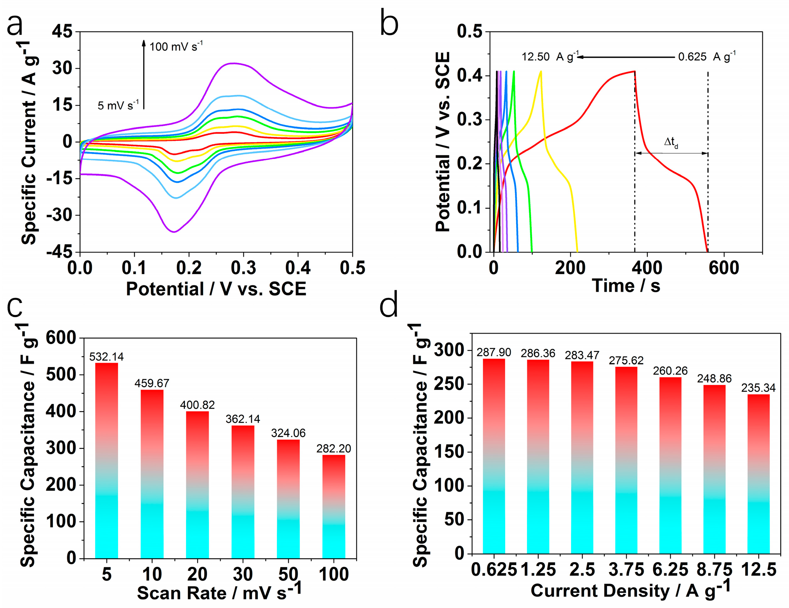
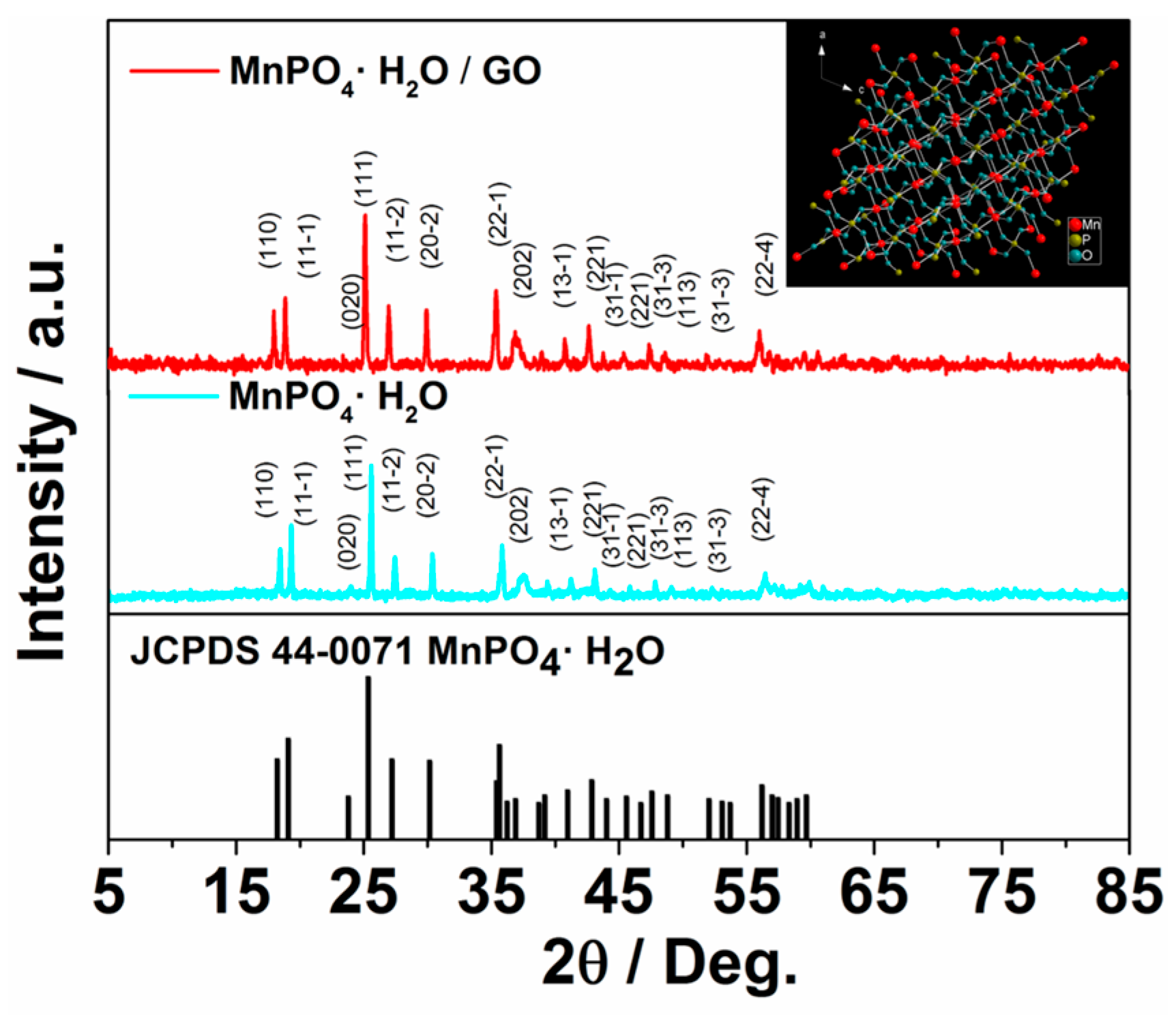
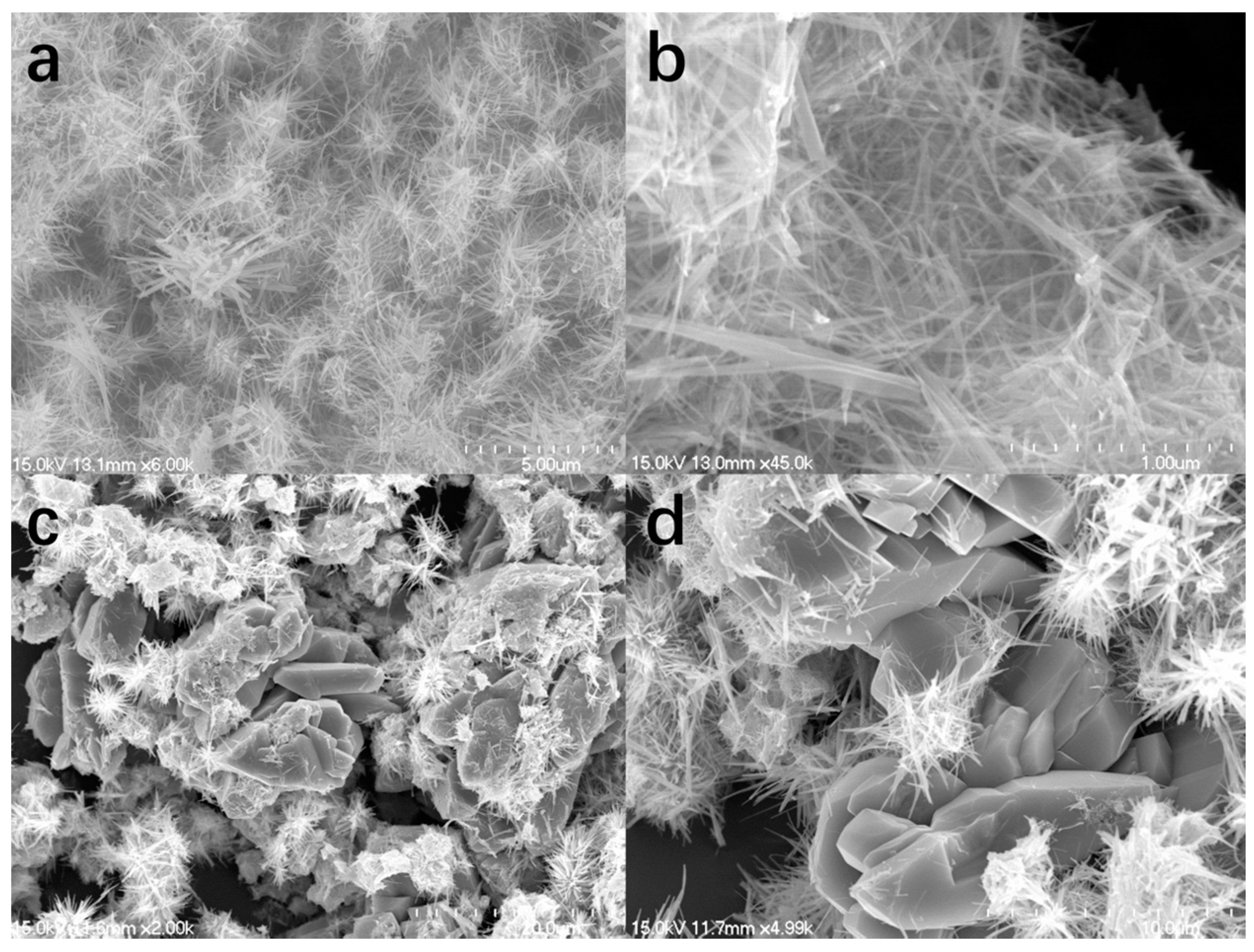
2. Results and Discussion

The crystal structure of the as-prepared MnPO4·H2O nanowire/GO composite material and MnPO4·H2O without GO were characterized by X-ray diffraction (XRD). The black vertical lines indicate the peak positions of standard MnPO4·H2O (JCPDS No.44-0071). From Figure 1, all of the diffraction peaks are sharp and can be well indexed with MnPO4·H2O (JCPDS No.44-0071). These diffraction peaks with narrow shapes indicate that the sample possesses good crystallinity. Usually, good crystallinity can improve the electrochemical performance of the material since the stable crystal structure cannot be destroyed easily during charge–discharge processes [25]. The inset in Figure 1 shows the possible schematic crystal structure of the sample, which is constructed according to the information from the standard PDF card [26]. However, peaks corresponding to GO were not observed. It may be caused by the fact that GO peaks are much weaker than MnPO4·H2O or the amounts are not sufficient enough to be detected.
Figure 2a,b are the scanning electron microscope (SEM) images of the as-obtained MnPO4·H2O nanowire/GO composite material. The MnPO4·H2O nanowire/GO composite is relatively homogeneous in morphology. They are mainly nanowires and twined together to be clew-like. In Figure 2c,d, the as-prepared MnPO4·H2O sample without GO seems not as homogeneous as MnPO4·H2O nanowire/GO composite in morphology. Some chunk particles can be observed. They may be ascribed to the existence of GO. As we know, there are some oxide functional groups on the surface of GO that can enhance its hydrophilicity. Therefore, GO may act as the surfactant in this system, which may lead to the formation of this homogeneous morphology [27,28,29]. In addition, GO, in this system, not only acts as a surfactant but also serves as a conductive agent in the sample, which contributes to the highly improved stability and great anti-aggregation ability during the charge–discharge process. In addition, the efficient conduction of electrons results in the increasing conductivity [30].
Transmission electron microscopy (TEM) images in Figure 3a–d show the uniform wire clews of the MnPO4·H2O nanowire/GO microarchitectures at different magnifications. In Figure 3a, it is clearly seen that the MnPO4·H2O nanowire/GO samples are twined wire-like. The inset in Figure 3a shows that the average width of nanowires is about 15 nm. Figure 3b–d display morphologies of the sample at a higher magnification, showing that the sample was nanowire morphology. It can be observed in HR-TEM images, shown in Figure 3e, that the lattice distance of the sample is ca. 0.487 nm, which matches well with the (110) lattice planes of a monoclinic MnPO4·H2O [26]. Furthermore, in the red dashed circle, GO can be clearly observed. Meanwhile, HAADF-STEM (high angle annular dark field-scanning transmission electron microscope) and EDS (energy dispersive spectrometer) line scan were also employed to characterize GO film coated on the sample surface, and the corresponding results can be seen in Figure 3f,g. EDS line scan data suggest that the thickness of the GO film was about 15 nm, which was different from that of Figure 3e, indicating that the GO film was coated on MnPO4·H2O nanowire with various thicknesses. And corresponding optical images before and after reaction can be seen from Figure S1.
X-ray photoelectron spectroscopy (XPS) recorded surface electronic state of C 1s and Mn 3p regions of MnPO4·H2O nanowire/GO material at high energy resolution are shown in Figure 4a,b, respectively. As shown in Figure 4a, the C 1s spectrum are fitted to three components. The most intense peak at lowest binding energy (BE) of 284.87 eV, which are attributed to C–C, C=C and C–H functional groups. In addition, the second component at BE of 286.35 eV is attributed to C–OH in GO or other substances with carbon–oxygen single bonds. The third peak with highest BE of 288.2 eV confirm C=O functional groups in MnPO4·H2O nanowire/GO material [31,32]. This evidence suggests the presence of C in the sample, and by Raman spectra in Figure 5, the existence of GO can be further confirmed. In Figure 4b, the Mn 3p spectrum for MnPO4·H2O nanowire/GO material is fitted to two components, which are centered at 641.29 eV and 653.82 eV belonging to Mn 2p3/2 and Mn 2p1/2. These results conform to the reported MnIII compounds [33,34].
Raman spectroscopy is a powerful method to characterize GO. Raman spectroscopy was employed to prove the existence of GO, and the results were shown in Figure 5. From Figure 5, it can be seen that there are two peaks respectively appearing at ~1348 cm−1 and ~1591 cm−1 in the as-obtained MnPO4·H2O nanowire/GO composite. For comparison, the GO precursor was tested as a reference. The results show that two peaks are located in the same regions, corresponding to characteristic D bands and G bands, where the D band depicts the disordered structural defects or edge areas, and the G band is a signature of in-plane vibration of sp2 bonded carbon atoms [35,36,37,38,39]. The as-obtained MnPO4·H2O sample without GO was also measured as shown in Figure 5. In the same wave number region, no G band or D band was detected, suggesting that no GO signal was detected in the MnPO4·H2O sample.
Cyclic voltammetry (CV), chronopotentiometry (CP) and electrochemical impedance spectrometry (EIS) were conducted in 3.0 M KOH solution as electrolytes at room temperature to investigate the performances of MnPO4·H2O nanowire/GO electrode materials. Figure 6a shows the CV curves of the electrode measured in 3.0 M KOH solution at the scan rates of 5, 10, 20, 30, 50 and 100 mV·s−1, respectively. It can be seen that the shapes of the curves obviously differ from that of typical EDLC. In Figure 6, the strong redox peaks at ~0.17 V and 0.3 V indicate that the energy storage is mainly ascribed to pseudocapacitance. The relatively symmetrical curves suggest that the redox reaction is reversible. Meanwhile, both the sizes of the loops and the redox peaks enlarge with the increasing of the scan rate, suggesting that the fast redox reactions occur during the scan processes. The possible reaction mechanism is shown below [1]:
Mn(OH)PO4 + e ↔ MnPO4 + OH
The specific capacitance of the materials can be calculated from CV test according to the Equation (1), [40] and the results are plotted in Figure 6c:
C s = Q V × m = I d V V × m × ν ,
where Cs, ΔV, m, I and ν are the specific capacitance (F·g−1), potential window (V), the mass of active material (g), current (A) and scan rate (V·s−1), respectively. In Figure 6c, when the scan rate is 5 mV·s−1, the specific capacitance is as high as 532.14 F·g−1. When the scan rates gradually increased to 10, 20, 30, 50 and 100 mV·s−1, the specific capacitances decreased to 459.67, 400.82, 362.14, 324.06 and 282.20 F·g−1, respectively. This phenomenon may result from the electrode polarization or the redox reaction occurring on the interface not being complete. In order to investigate the substrate effects on as-prepared material, we took a series of CV tests as control experiments based on Younis et al. work [41]. Herein, a piece of bare nickel foam was used as a work electrode. Relevant results can be seen in Figure S2. CV curves of bare nickel foam current collector are almost straight lines, as shown in Figure S2a, and the calculated specific capacitances of bare nickel foam electrode were negligible compared with the as-prepared material electrode.
CP is another useful method to evaluate energy storage performance of electrode material. Figure 6b shows that the galvanostatic charge–discharge (GCD) plots at current densities are 0.625, 1.250, 2.500, 3.750, 6.250, 8.750 and 12.50 A·g−1, respectively. These curves are symmetrical, indicating that the electrodes with excellent electrochemical capability and the redox process are reversible [42]. In addition, the corresponding charge–discharge times get shorter with the current densities enlarged. According to Equation (2), [43] the specific capacitance of the electrode material can be calculated as
C s = Q V × m = I t V × m ,
where Cs, ΔV, m, I and Δt are the specific capacitance (F·g−1), potential window (V), the mass of active material (g), current (A) and discharge time (s), respectively. The calculated results are displayed in Figure 6d. When the current densities are set as 0.625, 1.250, 2.500, 3.750, 6.250, 8.750 and 12.50 A·g−1, respectively, the corresponding specific capacitances are 287.90, 286.35, 283.46, 275.62, 260.26, 248.86, and 235.34 A·g−1, respectively. Based on the above analysis, it can be concluded that when the current density increases to 20 times its initial value, the specific capacitance retains ~82% of initial value, indicating the good rate ability of the material. This may be ascribed to the existence of GO, which can not only optimize the conductivity, but also benefit the total capacitance by enhancing the stability of materials attributed to its unique stable structure and great conductivity [30,44,45].
In comparison, the electrochemical performances of material synthesised without GO and other conditions kept the same as MnPO4·H2O nanowire/GO were tested. In this section, CV, CP and EIS were employed and conducted in 3.0 M KOH solution. The results can be seen in Figure 7.
Figure 7a displays the CV curves of the material tested at the scan rates of 5, 10, 20, 30, 50 and 100 mV·s−1, respectively. It is clear that the current densities that increase with the scan rates range from 5 mV·s−1 to 100 mV·s−1. The corresponding specific capacitances calculated through CV were shown in Figure 7c. When the scan rate is 5 mV·s−1, the specific capacitance is about 167.96 F·g−1, and the value decreases to 92.75 F·g−1 with the scan rate reaching 100 mV·s−1. Figure 7b is the CP curves of the tested sample, and the current densities, respectively, are 0.625, 1.250, 2.500, 3.750, 6.250, 8.750 and 12.50 A·g−1. From the results, it can be observed that the charge and discharge segments are symmetric, and specific capacitances were calculated by discharge time through Equation (2). Interestingly, the calculated results shown in Figure 7d are close to that of CV, suggesting that these results are reasonable. When the current density is 0.625 A·g−1, corresponding specific capacitance is 177.56 F·g−1. When current density is 12.50 A·g−1, twenty times of 0.625 A·g−1, specific capacitance is about 47.1% of initial level. Additionally, an EIS test was performed with MnPO4·H2O nanowire without GO electrode, and the result can be seen in Figure 7e. The bulk solution resistance Rs is 2.082 Ω, which is higher than MnPO4·H2O nanowire/GO electrode (1.081 Ω).
The results of the two samples’ CV, GCD and specific capacitances are displayed together in Figure 8. In Figure 8a, CV tests at scan rates of 5 mV·s−1 and 100 mV·s−1 of as-prepared samples with and without GO are shown. It is easy to find that no matter which scan rate it is, the current densities of MnPO4·H2O nanowire/GO are higher than those of another one without GO. During calculation, the integral part of Equation (1) is related to current density. Therefore, specific capacitances of the former one are higher than the latter one as shown in Figure 8c. Meanwhile, the GCD test shows a similar result. Figure 8b shows that the discharge time of MnPO4·H2O nanowire/GO in red is longer than the other one at the same current density, indicating a better performance. Specific capacitances at various current densities as shown in Figure 8d suggest that MnPO4·H2O nanowire/GO demonstrates a higher capacitance than MnPO4·H2O without GO.
To further investigate the performance of this material, CV and CP were performed in 3 M KOH solution with a symmetry two-electrode system. The corresponding test results can be seen in Figure 9.
As seen in Figure 9a, typical two-electrode CV curves were shown. With the scan rate increasing, the shape of the curves changes little, which indicates the great electrochemical reversibility and good rate ability of the as-prepared material. Additionally, GCD measurements were conducted, and showed that the electrode material has excellent electrochemical performance. From Figure 9b, it can be seen that the segments of charge and discharge are fairly symmetric, and negligible IR drops (voltage drop) are observed, which indicate that the material has great energy storage ability. The specific capacitance was calculated according to GCD measurement. Since the measurements were carried out on symmetric assemblies of materials and series capacitors, what is measured is actually 1/2 of the capacitance of the freestanding electrode. Therefore, the corresponding equation can be seen as below [46,47,48]:
C s = 2 I t V × m ,
where Cs, ΔV, m, I and Δt are the specific capacitance (F·g−1), potential window (V), the mass of active material loaded on each electrode (g), current (A) and discharge time (s), respectively. In addition, the calculated results were shown in Figure 9c. The GCD results show that when the measurement was conducted at low current density (0.625 A·g−1), the specific capacitance is 115.63 F·g−1, and when current density increases, the specific capacitance is decaying. Even when the current density increases to 20 times of initial value, the specific capacitance retains ~40%, which shows that this electrode material has excellent rate ability.
Furthermore, the cycle stability test was performed with electrode material for 1000 consecutive cycles at 1 A·g−1 current density. The performance can be seen in Figure 9d. It can be seen that after 1000 continuous cycles, the specific capacitance has no obvious decay. Importantly, it is 85.3% of initial specific capacitance, and the little decay of MnPO4·H2O nanowire/GO electrode may be ascribed to the slight collapse of MnPO4·H2O nanowire/GO composite when the ions are intercalated/extracted into the microstructures. Another reason is that electrode material inevitably falls off of nickel foam substrate.
The relationship between specific power and specific density is obtained according to CP measurement, namely the Ragone plot. In Figure 10, it can be observed that this MnPO4·H2O nanowire/GO electrode material has ultrahigh specific power, which is close to conventional solid state and electrolytic capacitors. However, compared with some reported similar phosphates [49,50], which are applied in supercapacitors, this specific energy (5.78 Wh·kg−1 in this work) is average, and the corresponding results can be seen in Figure S3. It drives us to develop other phosphates with high specific energy in the following research. This performance may result from the existence of GO carbon material, enhancing the electron transfer. Ultrahigh specific power means that this supercapacitor electrode material can serve some high power machines.
EIS was carried out to investigate the electrode kinetics and other properties of as-prepared material. In general, the impedance curves present two partially overlapped semicircles in the high and medium frequency regions and an inclined line in the low-frequency region as seen in Figure 11. The impedance of the material was calculated using ZSimpWin software (3.10 version, Princeton Applied Research , Oak Ridge, TN, USA, 2002) based on an equivalent circuit shown in Figure 11 as an inset. The EIS data can be fitted by a bulk solution resistance Rs, a charge-transfer resistance Rct, a pseudocapacitance Cp from redox process of materials, and a constant phase element (CPE) to simulate the double-layer capacitance. The charge-transfer resistance Rct, also called Faraday resistance, is 17.95 Ω calculated by ZSimpWin software, which is a limiting factor for the specific power of the supercapacitor [1]. Therefore, it is the low Faraday resistance that results in the high specific power. In addition, the bulk solution resistance Rs is calculated to be 1.081 Ω. This low Rs allows ions to run quickly, leading to fast reactions occurring on the material interface.

3. Materials and Methods

3.1. Materials

Ammonium phosphate tribasic trihydrate ((NH4)3PO4, Shanghai Zhanyun Chemical Co., Ltd., Shanghai, China), manganese nitrate solution (Mn(NO3)2, 50 wt %, Sinopharm Chemicals Reagent Co., Ltd., Shanghai, China), and GO (Nanjing XFNANO Materials Tech Co., Ltd., Nanjing , China) were purchased and used in the below syntheses without any purification.

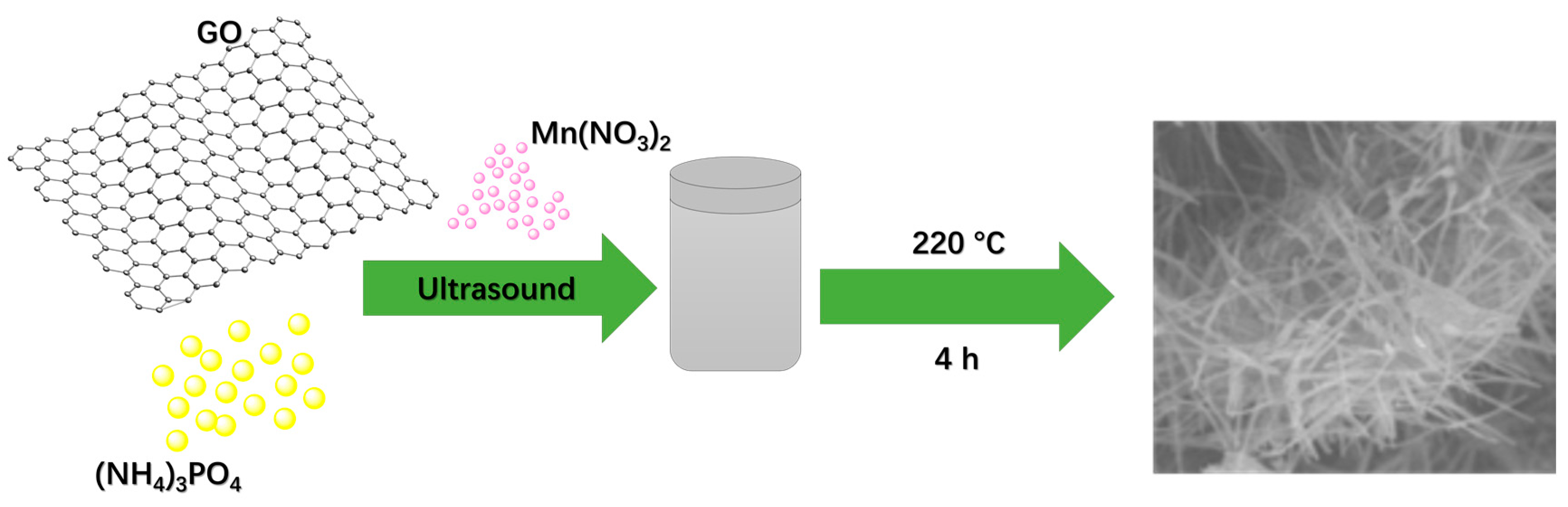
3.2. Synthesis of MnPO4·H2O Nanowire/GO Composite Material

For the synthesis of MnPO4·H2O nanowire/GO composite material, 5 mg GO and 200 mg (NH4)3PO4 were dispersed in 15 mL H2O through the ultrasound method in a beaker over 1 h. Then, a brown liquid was obtained. Subsequently, 2 mL Mn(NO3)2 solution was put into the above liquid, and with the addition of Mn(NO3)2 solution, a precipitate appeared. Afterwards, the mixture was transferred into a Teflon®-lined stainless steel autoclave and heated at 220 °C for 4 h. After reaction, a dark brown precipitate was obtained by centrifugation, thoroughly washed with plenty of distilled water and ethanol to remove the residual salts, and then dried at 60 °C in an oven. The synthesis process is illustrated in Scheme 1.

3.3. Electrochemical Measurement

The electrochemical study of MnPO4·H2O nanowire/GO composite material was conducted at a CHI 760E electrochemical work station (Shanghai Chenhua Instrument, Inc., Shanghai, China) in a three-electrode system and symmetric two-electrode system. In a three-electrode system, platinum electrode and saturated calomel electrode (SCE) were employed as counter and reference electrodes, respectively. The working electrode was made from the mixture of active material, acetylene black, and PTFE (polytetrafluoroethylene) with a weight ratio of 80:15:5, which was coated on a piece of nickel foam of ~1 cm2, and pressed into a thin foil at a pressure of ~5.0 MPa. After the abovementioned process, the typical mass loading of the active material is about 5 mg. As for the symmetric two-electrode system, two pieces of the as-obtained working electrode with the same mass loading were used. All of the tests were carried out in a 3.0 M KOH solution at room temperature. Before electrochemical measurement, we purged out O2 from the solution by the inert gas-Ar. Cyclic voltammetry, galvanostatic charge–discharge and electrochemical impedance spectroscopy methods were used to measure the performance of this composite material applied in SCs.

3.4. Characterization

The morphology of the sample was obtained by a Hitachi S-4700 scanning emission microscope (Hitachi Corporation, S-4700, Tokyo, Japan) and TecnaiG20 transmission electron microscope (FEI Tecnai G2 F20 S-TWIN TMP, Hongkong, China). HR-TEM, HAADF-STEM and EDS line scan were acquired by the TecnaiF20 transmission electron microscope (FEI Tecnai G2 F20 S-TWIN TMP, Hongkong, China) at 200 kV emission voltage. XRD analysis was carried out on a PANalytical X’Pert PRO MRD X-ray diffractometer (PANalytical Company, Amsterdam, The Netherlands) with Cu Kα radiation (λ = 1.54056 Å) operated at 40 kV and 30 mA. XPS was performed on a Thermo Scientific ESCALab 250Xi (Thermo Fisher Scientific Inc., Waltham, MA, USA) using 200 W monochromated Al Kα radiation, and Raman spectra were obtained with a Renishaw Invia Raman microscope with 532 nm laser excitation (Renishaw plc, Wotton-under-Edge, Glos., UK).

4. Conclusions

In this work, we successfully synthesized MnPO4·H2O nanowire/GO composite material through the one-pot hydrothermal method. Multiple measurement methods were employed to study the performances of the material. Importantly, CV, CP and EIS tests show that MnPO4·H2O nanowire/GO composite material displays better properties than MnPO4·H2O without GO, suggesting that it can be used as supercapacitor electrode material with excellent specific capacitance (287.9 F·g−1 and 115.63 F·g−1 at 0.625 A·g−1 in the three-electrode system and symmetric two-electrode system, respectively) and ultrahigh specific power (1.5 × 10⁵ W·kg−1), which indicates that this material is a promising electrode material used in high power applications.

Supplementary Materials

The following are available online at www.mdpi.com/2073-4344/6/12/198/s1, Figure S1: Optical images of GO dispersions before and after reaction. Figure S2: (a) CV tests of as-prepared MnPO4·H2O nanowire/graphene oxide material and bare nickel foam at different scan rates; inset: enlarged view of CV curves of bare nickel foam; (b) calculated specific capacitances of bare nickel foam electrode at scan rates of 5–100 mV s−1. Figure S3: Ragone plot of MnPO4·H2O nanowire/graphene oxide material and other similar phosphates.

Acknowledgments

This work was supported by the National Natural Science Foundation of China (Grant No. 51373111), the Suzhou Nano-Project (ZXG2012022), the State and Local Joint Engineering Laboratory for Novel Functional Polymeric Materials and the Priority Academic Program Development of Jiangsu Higher Education Institutions (PAPD).

Author Contributions

Bo Yan, Duan Bin and Yukou Du conceived and designed the experiments; Bo Yan performed the experiments; Zhiping Xiong, Ke Zhang, Fangfang Ren and Caiqin Wang analyzed the data; Bo Yan wrote the paper.

Conflicts of Interest

The authors declare no conflict of interest.

References

  1. Conway, B.E. Electrochemical supercapacitors. In Scientific Fundamentals and Technological Applications; Kluwer Academic/Plenum Press: New York, NY, USA, 1999. [Google Scholar]
  2. Arico, A.S.; Bruce, P.; Scrosati, B.; Tarascon, J.M.; Van Schalkwijk, W. Nanostructured materials for advanced energy conversion and storage devices. Nat. Mater. 2005, 4, 366–377. [Google Scholar] [CrossRef] [PubMed]
  3. Simon, P.; Gogotsi, Y. Materials for electrochemical capacitors. Nat. Mater. 2008, 7, 845–854. [Google Scholar] [CrossRef] [PubMed]
  4. Brownson, D.A.C.; Kampouris, D.K.; Banks, C.E. An overview of graphene in energy production and storage applications. J. Power Sources 2011, 196, 4873–4885. [Google Scholar] [CrossRef]
  5. Huang, Y.; Liang, J.; Chen, Y. An overview of the applications of graphene-based materials in supercapacitors. Small 2012, 8, 1805–1834. [Google Scholar] [CrossRef] [PubMed]
  6. Liu, C.; Yu, Z.; Neff, D.; Zhamu, A.; Jang, B.Z. Graphene-based supercapacitor with an ultrahigh energy density. Nano Lett. 2010, 10, 4863–4868. [Google Scholar] [CrossRef] [PubMed]
  7. Meng, Y.; Zhao, Y.; Hu, C.; Cheng, H.; Hu, Y.; Zhang, Z.; Shi, G.; Qu, L. All-graphene core-sheath microfibers for all-solid-state, stretchable fibriform supercapacitors and wearable electronic textiles. Adv. Mater. 2013, 25, 2326–2331. [Google Scholar] [CrossRef] [PubMed]
  8. Yue, R.; Ren, F.; Wang, C.; Xu, J.; Du, Y. Facile preparation of flower-like graphene-nanosheet clusters with the assistance of copper particles and their application in supercapacitors. RSC Adv. 2014, 4, 500–504. [Google Scholar] [CrossRef]
  9. Zhao, X.; Zheng, B.; Huang, T.; Gao, C. Graphene-based single fiber supercapacitor with a coaxial structure. Nanoscale 2015, 7, 9399–9404. [Google Scholar] [CrossRef] [PubMed]
  10. Zhang, Z.; Zhang, Y.; Song, R.; Wang, M.; Yan, F.; He, L.; Feng, X.; Fang, S.; Zhao, J.; Zhang, H. Manganese(II) phosphate nanoflowers as electrochemical biosensors for the high-sensitivity detection of ractopamine. Sens. Actuators B 2015, 211, 310–317. [Google Scholar] [CrossRef]
  11. Stanislav, F.A.; Zhi, L.; Rute, A.S.F. New template-free layered manganese(III) phosphate: Hydrothermal synthesis, ab initio structural determination, and magnetic properties. Chem. Mater. 2007, 19, 6025–6029. [Google Scholar]
  12. Nam, K.M.; Cheon, E.A.; Shin, W.J.; Bard, A.J. Improved photoelectrochemical water oxidation by the WO3/CuWO4 composite with a manganese phosphate electrocatalyst. Langmuir 2015, 31, 10897–10903. [Google Scholar] [CrossRef] [PubMed]
  13. Guo, H.; Wu, C.; Liao, L.; Xie, J.; Zhang, S.; Zhu, P.; Cao, G.; Zhao, X. Performance improvement of lithium manganese phosphate by controllable morphology tailoring with acid-engaged nano engineering. Inorg. Chem. 2015, 54, 667–674. [Google Scholar] [CrossRef] [PubMed]
  14. Minakshi, S.M.; Biswal, A.; Mitchell, D.; Jones, R.; Fernandez, C. Correlation among physical and electrochemical behaviour of nanostructured electrolytic manganese dioxide from leach liquor and synthetic for aqueous asymmetric capacitor. Phys. Chem. Chem. Phys. 2016, 18, 4711–4720. [Google Scholar] [CrossRef] [PubMed]
  15. Zhang, K.; Han, X.; Hu, Z.; Zhang, X.; Tao, Z.; Chen, J. Nanostructured Mn-based oxides for electrochemical energy storage and conversion. Chem. Soc. Rev. 2015, 44, 699–728. [Google Scholar] [CrossRef] [PubMed]
  16. Di, L.D.; Hu, T.; Hassoun, J. Electrochemical features of LiMnPO4 olivine prepared by sol-gel pathway. J. Alloys Compd. 2017, 693, 730–737. [Google Scholar]
  17. Huang, Y.; Chernova, N.A.; Yin, Q.; Wang, Q.; Quackenbush, N.F.; Leskes, M. What Happens to LiMnPO4 upon Chemical Delithiation? Inorg. Chem. 2016, 55, 4335–4343. [Google Scholar] [CrossRef] [PubMed]
  18. Aravindan, V.; Gnanaraj, J.; Lee, Y.S.; Madhavi, S. LiMnPO4—A next generation cathode material for lithium-ion batteries. J. Mater. Chem. A 2013, 1, 3518–3539. [Google Scholar] [CrossRef]
  19. Su, J.; Liu, Z.Z.; Long, Y.F.; Yao, H.; Lv, X.Y.; Wen, Y.X. Enhanced electrochemical performance of LiMnPO4/C prepared by microwave-assisted solvothermal method. Electrochim. Acta 2015, 173, 559–565. [Google Scholar] [CrossRef]
  20. Chen, L.; Dilena, E.; Paolella, A.; Bertoni, G.; Ansaldo, A.; Colombo, M. Relevance of LiPF6 as Etching Agent of LiMnPO4 Colloidal Nanocrystals for High Rate Performing Li-ion Battery Cathodes. ACS Appl. Mater Interfaces 2016, 8, 4069–4075. [Google Scholar] [CrossRef] [PubMed]
  21. Kim, T.; Jung, G.; Yoo, S.; Suh, K.S.; Ruoff, R.S. Activated graphene-based carbons as supercapacitor electrodes with macro- and mesopores. ACS Nano 2013, 7, 6899–6905. [Google Scholar] [CrossRef] [PubMed]
  22. Shao, Y.; El-Kady, M.F.; Wang, L.J.; Zhang, Q.; Li, Y.; Wang, H. Graphene-based materials for flexible supercapacitors. Chem. Soc. Rev. 2015, 44, 3639–3665. [Google Scholar] [CrossRef] [PubMed]
  23. Ren, F.; Wang, H.; Zhai, C.; Zhu, M.; Yue, R.; Du, Y. Clean method for the synthesis of reduced graphene oxide-supported PtPd alloys with high electrocatalytic activity for ethanol oxidation in alkaline medium. ACS Appl. Mater Interfaces 2014, 6, 3607–3614. [Google Scholar] [CrossRef] [PubMed]
  24. Zou, C.; Yang, B.; Bin, D.; Wang, J.; Li, S.; Yang, P. Electrochemical synthesis of gold nanoparticles decorated flower-like graphene for high sensitivity detection of nitrite. J. Colloid Interface Sci. 2017, 488, 135–141. [Google Scholar] [CrossRef] [PubMed]
  25. Pang, H.; Liu, Y.; Li, J.; Ma, Y.; Li, G.; Ai, Y.; Chen, J.; Zhang, J.; Zheng, H. Cobalt phosphite microarchitectures assembled by ultralong nanoribbons and their application as effective electrochemical capacitor electrode materials. Nanoscale 2013, 5, 503–507. [Google Scholar] [CrossRef] [PubMed]
  26. Miguel, A.G.A.; Attfield, J.P.; Bruquea, S.; Fernando, P. Magnetic structures of MnPO4·D2O and MnAsO4·D2O from time-of-flight neutron powder diffraction data. J. Mater. Chem. 1992, 2, 501–505. [Google Scholar]
  27. Cote, L.J.; Kim, J.; Zhang, Z.; Sun, C.; Huang, J. Tunable assembly of graphene oxide surfactant sheets: Wrinkles, overlaps and impacts on thin film properties. Soft Matter 2010, 6, 6096–6101. [Google Scholar] [CrossRef]
  28. Kazi, S.N.; Badarudin, A.; Zubir, M.N.; Ming, H.N.; Misran, M.; Sadeghinezhad, E.; Mehrali, M.; Syuhada, N.I. Investigation on the use of graphene oxide as novel surfactant to stabilize weakly charged graphene nanoplatelets. Nanoscale Res. Lett. 2015, 10. [Google Scholar] [CrossRef] [PubMed]
  29. Kim, F.; Cote, L.J.; Huang, J. Graphene oxide: Surface activity and two-dimensional assembly. Adv. Mater. 2010, 22, 1954–1958. [Google Scholar] [CrossRef] [PubMed]
  30. Peng, S.; Han, X.; Li, L.; Zhu, Z.; Cheng, F.; Srinivansan, M.; Adam, S.; Ramakrishna, S. Unique cobalt sulfide/reduced graphene oxide composite as an anode for sodium-ion batteries with superior rate capability and long cycling stability. Small 2016, 12, 1359–1368. [Google Scholar] [CrossRef] [PubMed]
  31. Akhavan, O. Bacteriorhodopsin as a superior substitute for hydrazine in chemical reduction of single-layer graphene oxide sheets. Carbon 2015, 81, 158–166. [Google Scholar] [CrossRef]
  32. Govindhan, M.; Chen, A. Simultaneous synthesis of gold nanoparticle/graphene nanocomposite for enhanced oxygen reduction reaction. J. Power Sources 2015, 274, 928–936. [Google Scholar] [CrossRef]
  33. Biesinger, M.C.; Payne, B.P.; Grosvenor, A.P.; Lau, L.W.M.; Gerson, A.R.; Smart, R.S.C. Resolving surface chemical states in XPS analysis of first row transition metals, oxides and hydroxides: Cr, Mn, Fe, Co and Ni. Appl. Surface Sci. 2011, 257, 2717–2730. [Google Scholar] [CrossRef]
  34. Huang, Y.; Fang, J.; Omenya, F.; O’Shea, M.; Chernova, N.A.; Zhang, R.; Wang, Q.; Quackenbush, N.F.; Piper, L.F.J.; Scanlon, D.O.; et al. Understanding the stability of MnPO4. J. Mater. Chem. A 2014, 2, 12827–12834. [Google Scholar] [CrossRef]
  35. Yang, B.; Wang, J.; Bin, D.; Zhu, M.; Yang, P.; Du, Y. A three dimensional Pt nanodendrite/graphene/MnO2 nanoflower modified electrode for the sensitive and selective detection of dopamine. J. Mater. Chem. B 2015, 3, 7440–7448. [Google Scholar] [CrossRef]
  36. Heller, E.J.; Yang, Y.; Kocia, L.; Chen, W.; Fang, S.; Borunda, M.; Kaxiras, E. Theory of graphene raman scattering. ACS Nano 2016, 10, 2803–2818. [Google Scholar] [CrossRef] [PubMed]
  37. Wang, C.; Du, J.; Wang, H.; Zou, C.; Jiang, F.; Yang, P.; Du, Y. A facile electrochemical sensor based on reduced graphene oxide and Au nanoplates modified glassy carbon electrode for simultaneous detection of ascorbic acid, dopamine and uric acid. Sens. Actuators B 2014, 204, 302–309. [Google Scholar] [CrossRef]
  38. Zhai, C.; Zhu, M.; Bin, D.; Ren, F.; Wang, C.; Yang, P. Two dimensional MoS2/graphene composites as promising supports for Pt electrocatalysts towards methanol oxidation. J. Power Sources 2015, 275, 483–488. [Google Scholar] [CrossRef]
  39. Ren, F.; Zhai, C.; Zhu, M.; Wang, C.; Wang, H.; Bin, D. Facile synthesis of PtAu nanoparticles supported on polydopamine reduced and modified graphene oxide as a highly active catalyst for methanol oxidation. Electrochim. Acta 2015, 153, 175–183. [Google Scholar] [CrossRef]
  40. Oraon, R.; De, A.A.; Tiwari, S.K.; Nayak, G.C. Enhanced specific capacitance of self-assembled three-dimensional carbon nanotube/layered silicate/polyaniline hybrid sandwiched nanocomposite for supercapacitor applications. ACS Sustain. Chem. Eng. 2016, 4, 1392–1403. [Google Scholar] [CrossRef]
  41. Younis, A.; Chu, D.; Li, S. Ethanol-directed morphological evolution of hierarchical CeOx architectures as advanced electrochemical capacitors. J. Mater. Chem. A 2015, 3, 13970–13977. [Google Scholar] [CrossRef]
  42. Wan, H.; Jiang, J.; Yu, J.; Xu, K.; Miao, L.; Zhang, L.; Chen, H.; Ruan, Y. NiCo2S4 porous nanotubes synthesis via sacrificial templates: High-performance electrode materials of supercapacitors. CrystEngComm 2013, 15, 7649–7651. [Google Scholar] [CrossRef]
  43. Qiu, K.; Lu, Y.; Zhang, D.; Cheng, J.; Yan, H.; Xu, J.; Liu, X.; Kim, J.; Luo, Y. Mesoporous, hierarchical core/shell structured ZnCo2O4/MnO2 nanocone forests for high-performance supercapacitors. Nano Energy 2015, 11, 687–696. [Google Scholar] [CrossRef]
  44. Cui, X.; Lv, R.; Sagar, R.U.R.; Liu, C.; Zhang, Z. Reduced graphene oxide/carbon nanotube hybrid film as high performance negative electrode for supercapacitor. Electrochim. Acta 2015, 169, 342–350. [Google Scholar] [CrossRef]
  45. Zhu, Y.; Cui, H.; Meng, X.; Zheng, J.; Yang, P.; Li, L.; Wang, Z.; Jia, S.; Zhu, P. Chlorine-induced in situ regulation to synthesize graphene frameworks with large specific area for excellent supercapacitor performance. ACS Appl. Mater. Interfaces 2016, 8, 6481–6487. [Google Scholar] [CrossRef] [PubMed]
  46. Portet, C.; Taberna, P.L.; Simon, P.; Flahaut, E.; Laberty-Robert, C. High power density electrodes for carbon supercapacitor applications. Electrochim. Acta 2005, 50, 4174–4181. [Google Scholar] [CrossRef] [Green Version]
  47. Rakhi, R.B.; Chen, W.; Cha, D.; Alshareef, H.N. High performance supercapacitors using metal oxide anchored graphene nanosheet electrodes. J. Mater. Chem. 2011, 21, 16197–16204. [Google Scholar] [CrossRef]
  48. Reddy, A.L.M.; Ramaprabhu, S. Nanocrystalline metal oxides dispersed multiwalled carbon nanotubes as supercapacitor electrodes. J. Phys. Chem. C 2007, 111, 7727–7734. [Google Scholar] [CrossRef]
  49. Minakshi, M.; Meyrick, D.; Appadoo, D. Maricite (NaMn1/3Ni1/3Co1/3PO4)/activated carbon: Hybrid capacitor. Energy Fuels 2013, 27, 3516–3522. [Google Scholar] [CrossRef]
  50. Minakshi, M.; Mitchell, D.; Jones, R.; Alenazey, F.; Watcharatharapong, T.; Chakraborty, S.; Ahuja, R. Synthesis, structural and electrochemical properties of sodium nickel phosphate for energy storage devices. Nanoscale 2016, 8, 11291–11305. [Google Scholar] [CrossRef] [PubMed]
Figure 1. XRD (X-Ray Diffraction) patterns of as-prepared MnPO4·H2O nanowire/GO (graphene oxide) composite material, as-prepared MnPO4·H2O sample without GO, and standard MnPO4·H2O (JCPDS-44-0071). Inset: the possible schematic crystal structures of MnPO4·H2O.
Catalysts 06 00198 g001
Figure 2. (a,b) SEM (scanning electron microscope) images of as-prepared MnPO4·H2O nanowire/GO composite material; (c,d) and as-prepared MnPO4·H2O sample without GO.
Catalysts 06 00198 g002
Figure 3. (ad) TEM (transmission electron microscope) images of MnPO4·H2O nanowire/GO composite material at different magnifications (the inset in Figure 3a: the width distribution of the as-prepared sample); (e) HR-TEM (high resolution- transmission electron microscope) image of the MnPO4·H2O nanowire/GO; (f,g) high-magnification HAADF-STEM (high angle annular dark field-scanning transmission electron microscope) image and EDS (energy dispersive spectrometer) line scan.
Catalysts 06 00198 g003
Figure 4. (a) C 1s XPS (X-ray photoelectron spectroscopy) of MnPO4·H2O nanowire/GO composite material; (b) Mn 2p3/2 and 2p1/2 spectra in this material.
Catalysts 06 00198 g004
Figure 5. Raman spectra of MnPO4·H2O nanowire/GO composite, as-prepared MnPO4·H2O sample without GO and GO reactant.
Catalysts 06 00198 g005
Figure 6. (a) CV (Cyclic voltammetry) curves at scan rates of 5–100 mV·s−1 of as-prepared MnPO4·H2O nanowire/GO material in a three-electrode system; (b) GCD (galvanostatic charge–discharge) curves of MnPO4·H2O nanowire/GO material at current densities of 0.625–12.5 A·g−1; (c) specific capacitances derived from the CV curves by Equation (1); and (d) specific capacitances calculated from the GCD curves by Equation (2) at various charge–discharge rates.
Catalysts 06 00198 g006
Figure 7. (a) CV curves of the sample without GO material in the three-electrode system; (b) GCD curves of the sample without GO at various current densities; (c) specific capacitances derived from the CV curves; (d) specific capacitances calculated from the GCD curves; (e) EIS (electrochemical impedance spectroscopy) for MnPO4·H2O nanowire without GO electrode.
Catalysts 06 00198 g007
Figure 8. (a) CV curves of MnPO4·H2O nanowire/GO and MnPO4·H2O without GO at 5 mV·s−1 and 100 mV·s−1 in the three-electrode system; (b) the discharge times of the two samples at 0.625 A·g−1; (c) specific capacitances of the two samples derived from the CV measurement; (d) specific capacitances of the two samples calculated from the GCD curves.
Catalysts 06 00198 g008
Figure 9. (a) CV experiments of as-prepared MnPO4·H2O nanowire/GO in a symmetric double-electrode system; (b) GCD curves of MnPO4·H2O nanowire/GO; (c) specific capacitances calculated from the GCD curves; (d) charge–discharge cyclic test of MnPO4·H2O nanowire/GO in a symmetric double-electrode system at the current density of 1 A·g−1.
Catalysts 06 00198 g009
Figure 10. The Ragone plot of MnPO4·H2O nanowire/GO composite material in the symmetric double-electrode system.
Catalysts 06 00198 g010
Figure 11. EIS (electrochemical impedance spectroscopy) for MnPO4·H2O nanowire/GO electrode and fitting plots (inset: corresponding equivalent circuit consisting of a bulk solution resistance Rs, a charge-transfer Rct, a pseudocapacitive element Cp from redox process of MnPO4·H2O nanowire/GO, and a constant phase element (CPE) to account for the double-layer capacitance).
Catalysts 06 00198 g011
Scheme 1. The process for the preparation of MnPO4·H2O nanowire/GO (graphene oxide) composite material.
Catalysts 06 00198 sch001

