Article

Evaluation of a Pilot-Scale Water Treatment System with Passive Aerated, Membraneless Microbial Fuel Cell

by
Zabdiel A. Juarez
1,
Víctor Ramírez
2,
Carlos Hernández-Benítez
1,
Luis A. Godínez
3,
Irma Robles Gutierrez
1 and
Francisco J. Rodríguez-Valadez
1,*
1
Centro de Investigación y Desarrollo Tecnológico en Electroquímica SC., Parque Tecnológico Querétaro Sanfandila s/n, Pedro Escobedo, Querétaro 76703, Mexico
2
Division de Ingeniería Ambiental, Universidad Tecnológica de Querétaro, Av. Pie de la Cuesta 2501, Nacional, Querétaro 76148, Mexico
3
Centro de Investigación en Química para la Economia Circular, Universidad Autónoma de Querétaro, Centro Universitario, Cerro de las Campanas s/n, Querétaro 76010, Mexico
*
Author to whom correspondence should be addressed.
Catalysts 2025, 15(8), 765; https://doi.org/10.3390/catal15080765 (registering DOI)
Submission received: 25 June 2025 / Revised: 6 August 2025 / Accepted: 8 August 2025 / Published: 9 August 2025

Abstract

Wastewater treatment has become a priority in the global attempt to address environmental pollution. Conventional wastewater treatment processes are often limited by their high energy consumption, so it is necessary to develop new technologies. This work shows the results obtained using a passive aerated membraneless microbial fuel cell (PAML-MFC) system consisting of 10 individual units, designed to treat 1000 L/day of real wastewater, using granular activated carbon anodes and cathodes. The pilot-scale water treatment system under study combines design and materials to result in low-cost operation. After 300 days of treating real wastewater originally characterized by a chemical oxygen demand (COD) value of 500 mg/L on average, it was found that the PAML-MFC under study removed 60 to 80% of the COD contained in real wastewater. Under these conditions, the individual MFCs reached an average power density below 1 mW/m3.

1. Introduction

Wastewater generation has become a serious pollution problem that requires increased attention. Currently, wastewater treatment technologies are applied in many regions and countries and are commonly based on conventional processes that are effective in reducing pollutants [1]. However, the energy consumption of some of these technologies, particularly in activated sludge reactors, is a matter of great concern [2,3,4]. In this context, it is of paramount importance to develop novel technological alternatives to maintain pollutant removal efficiency while reducing the corresponding energy consumption. A new approach, based on the implementation of microbial fuel cells (MFCs) as wastewater treatment units, has been proven to be a viable and attractive alternative [5,6,7,8]. An MFC is a bio-electrochemical device that takes advantage of microbial respiration to transform pollutants in wastewater directly into electrical energy [9,10]. An MFC consists of an anode where the pollutant-consuming biofilm grows on its surface, which is separated by a cation membrane from a cathode, where oxygen reduction takes place. The microbes oxidize the organic matter, producing electrons that flow through the anode and an external circuit to the cathode, resulting in electrical current [11]. Also, protons travel from the anodic to the cathodic compartment through the membrane to complete the cathodic reduction reaction. In general, the use of ion-exchange membranes increases the cost of an MFC, so a membraneless MFC is attractive [12,13]. Also, the oxygen used as an electron acceptor in the cathode can be supplied by passive aeration, thus reducing the oxygen supply cost [14].
MFCs, on the other hand, have been used to successfully treat wastewater effluents on pilot or semi-pilot scales, achieving similar COD removals as those obtained by conventional processes [15,16,17,18,19,20,21,22,23,24,25,26,27,28]. Li et al., for example, evaluated the use of granular activated carbon (GAC) as a tridimensional anode connected by graphite rods and multiple carbon cloth cathodes in a pilot-scale system with four 16 L MFCs fed with real wastewater. The experimental results indicated that the system removed near 80% of the COD with retention times of 5, 10, and 20 h while generating power densities in the order of 300 mW/m3 [23]. Hsu et al. implemented an 88 L MFC system using packed bed granules, carbon pleats, and granule bundles in the anode, with carbon cloth in a pleated arrangement in the cathode. This arrangement reached a 93% COD removal under continuous feeding. In this case, however, the coulombic efficiency was less than 1%, indicating that organic removal was basically related to an anaerobic fermentation process that did not produce electricity [24]. It is also interesting to point out that an MFC system using brewery wastewater can be energetically self-sustaining since the treatment process is capable of supplying the required energy, as shown by Dong et al., who used a 90 L stackable pilot MFC. These authors found that the produced power density (0.097 kWh/m3) was higher than the 0.027 kWh/m3 required by the pumping system, thus obtaining a positive energy balance that achieved an 87% COD removal for the influent [25]. In other systems, COD and nitrogen could be efficiently removed (79% and 71%, respectively) using a 250 L stackable horizontal MFC arrangement in which carbon brush anodes and carbon mesh cathodes were employed [26]. However, one of the largest systems for wastewater treatment that have been reported is a 1000 L parallel-plate modularized MFC arrangement that was built using 50 individual modules and protonic exchange membranes. This system removes between 70 and 90% of the COD contained in municipal wastewater (250 mg/L of COD on average) [27]. Although there are some relevant reports dealing with high-volume MFCs, to the best of our knowledge, there is scarce information on the performance of continuous MFCs using real wastewater and particularly of the use of low-cost GAC anodes and cathodes. In this context, this work shows the experimental results obtained from a study on the performance of a cost-optimized arrangement membraneless MFC prototype, processing 1000 L/day of real wastewater (pilot scale). The proposed design uses low-cost granular activated carbon as the electrode, a novel membraneless arrangement, and a cathodic area with enhanced aeration that does not require the use of mechanical aerators.

2. Results and Discussion

2.1. COD Removal of MFC System

As can be seen in Figure 1, the soluble COD of the real wastewater that was fed to the PAML-MFC ranged from 85 to 790 mg/L with a maximum value of 1267 mg/L. The average value fell near 500 mg/L, as would be expected for a typical real sanitary wastewater sample.
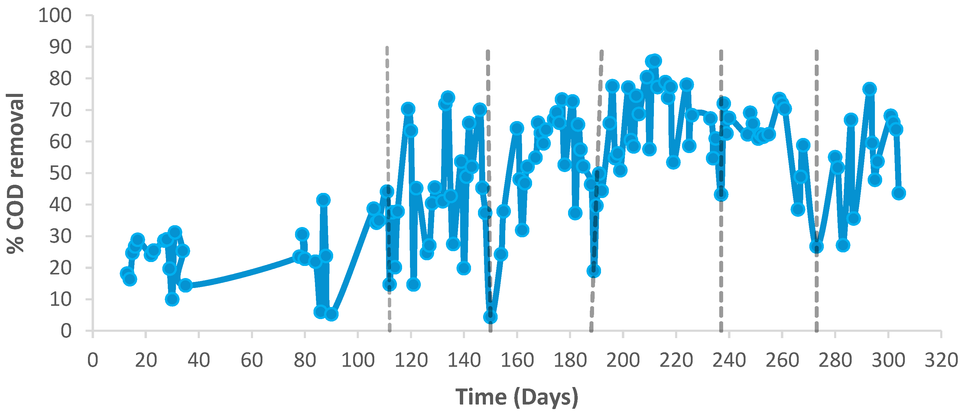
The results obtained for the removal of COD indicate low removal efficiencies at the beginning of the operation that continuously increase as the PAML-MFC stabilization process progresses (Figure 2). According to these results, after 119 days it is possible to achieve COD removal efficiencies close to 70%; after day 165 to the end of the experiment, the COD removal values are relatively stable between 60 and 80%, with negative variations on days 182–190, 237, and 266 to 283. The fluctuations in COD removal efficiency may be attributed to variations in the influent COD concentration, considering that real wastewater was feed to the PAML_MFC. It should also be considered that the pit from which the wastewater was collected received rainwater, which could have affected the COD levels of the influent and led to significant fluctuations in the COD removal efficiency achieved.
The removal efficiency achieved with our system, however, is comparable to that reported in various studies involving pilot-scale microbial fuel cells. For instance, Liang et al. achieved COD removal rates between 70% and 90% using a modular MFC system with membranes treating 1000 L of municipal wastewater [27]. Similarly, Rossi et al. treated 850 L of domestic wastewater using a passively aerated MFC configuration, obtaining a COD removal efficiency of 49% [29].
It is clear that after several months of operation, the efficiency of the system decreased significantly suddenly and periodically, so a maintenance procedure was necessary to clean up the electrodes. While the anodes were treated with a retro-washing process, cathodes were cleaned with a rinsing procedure to eliminate the attached biomass (days 112, 150, 190, 237 and 273). As can be seen in Figure 2, this operation resulted in a noticeable PAML-MFC efficiency recovery. As stated by Zhang et al., excessive biofilm accumulation on activated carbon anodes in microbial fuel cells (MFCs) can lead to a measurable decline in chemical oxygen demand (COD) removal efficiency over time. Although the high porosity and surface area of activated carbon initially enhance microbial colonization and organic matter degradation, progressive biofilm thickening and pore clogging reduce substrate diffusion into the electrode’s interior. This mass transfer limitation diminishes the accessibility of biodegradable compounds to active microbial communities, particularly within the deeper, potentially anaerobic regions of the biofilm [30]

2.2. Physicochemical Parameters of the MFC System

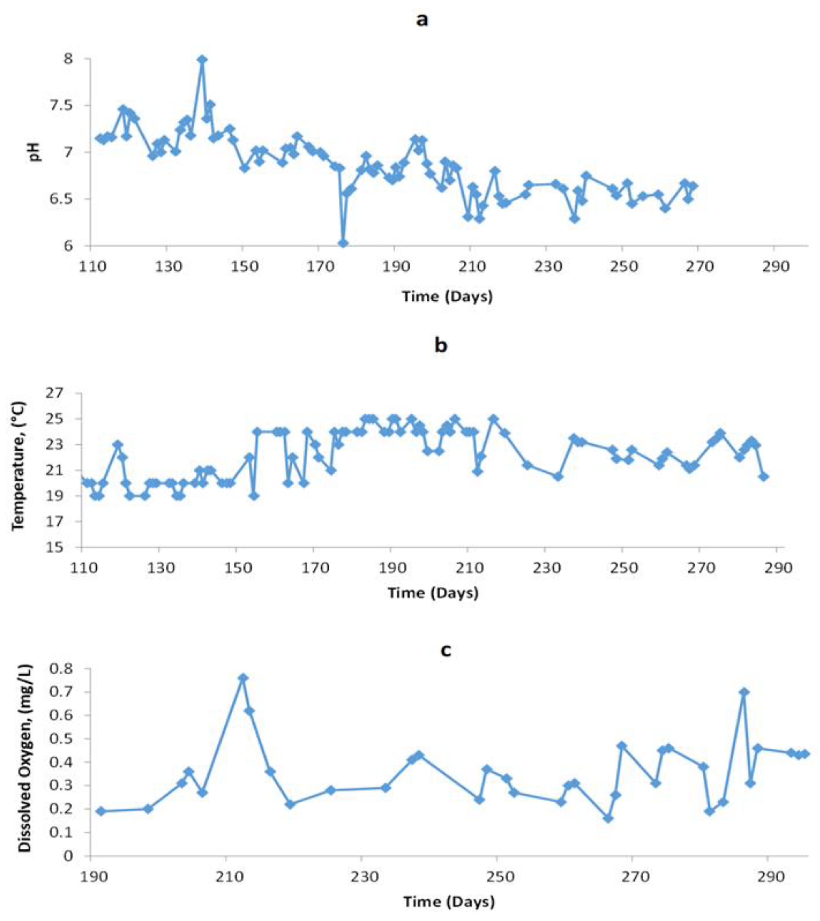
Experimental data in Figure 3a shows that the pH of the wastewater fed to the PAML-MFC fell between 6.3 and 8, indicating suitable conditions for the operation of a biological system [31]. It is noteworthy that there was a drop in the pH to 6 in day 176, which could have been due to abnormal discharge of the real wastewater influent. In spite of this observation, it can be assumed that, for the duration of this experiment, there was no significant acid or basic discharges that could have affected the activity and integrity of the biomass attached to the anode of the PAML-MFC.
As far as the temperature is concerned, measurements of the exposed cathodic zone revealed fluctuations between 19 and 25 °C, with an average value of 21 °C (see Figure 3b). This experimental condition allowed the proper operation of the biological systems of the MFC. It is important to point out that the temperature was determined once a day at noon so there could have been some variation during the day. Despite the fact that the temperature in the anodic region was not determined, it was assumed to be relatively stable since the processes taking place in this zone are enclosed within the walls of the reactor.
In order to assess the possible influence of oxygen concentration in the cathodic zone of the reactor on the overall performance of the PAML-MFC, the oxygen was measured in water. As can be seen in Figure 3c, the concentration of dissolved oxygen (DO) was relatively constant throughout the experiment. While most of the obtained values fell between 0.2 and 0.4 mg/L, none of the data collected was larger than 0.8 mg/L, and, therefore, the variations in oxygen concentration could not have significantly affected the MFC performance.
According to the measured pH, temperature, and dissolved oxygen at the cathode, the environmental conditions are suitable for the proper operation of the PAML-MFC.

2.3. Electrical Parameters of the PAML-MFC System

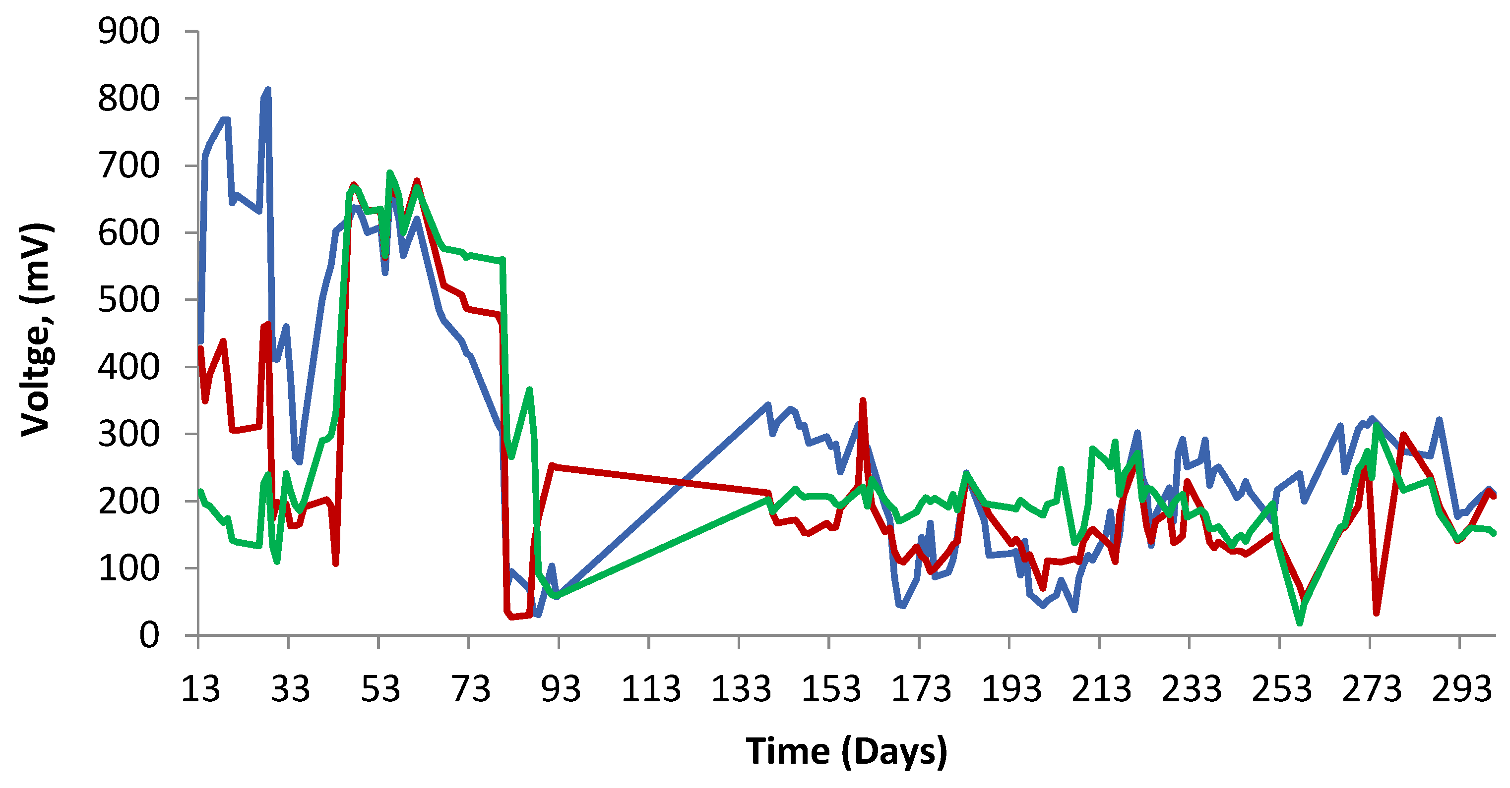
Electrical parameters measurements show that at the beginning of the experiment the voltage varied from less than 50 mV to near 800 mV. However, after 140 days of operation, when stabilization of the system was reached, almost all values were in the 100 to 350 mV range, with an average value of around 200 mV (Figure 4). Considering that real wastewater was used as feedstock, the voltage produced is in good agreement with previous reports for MFCs designed for wastewater treatment [28].
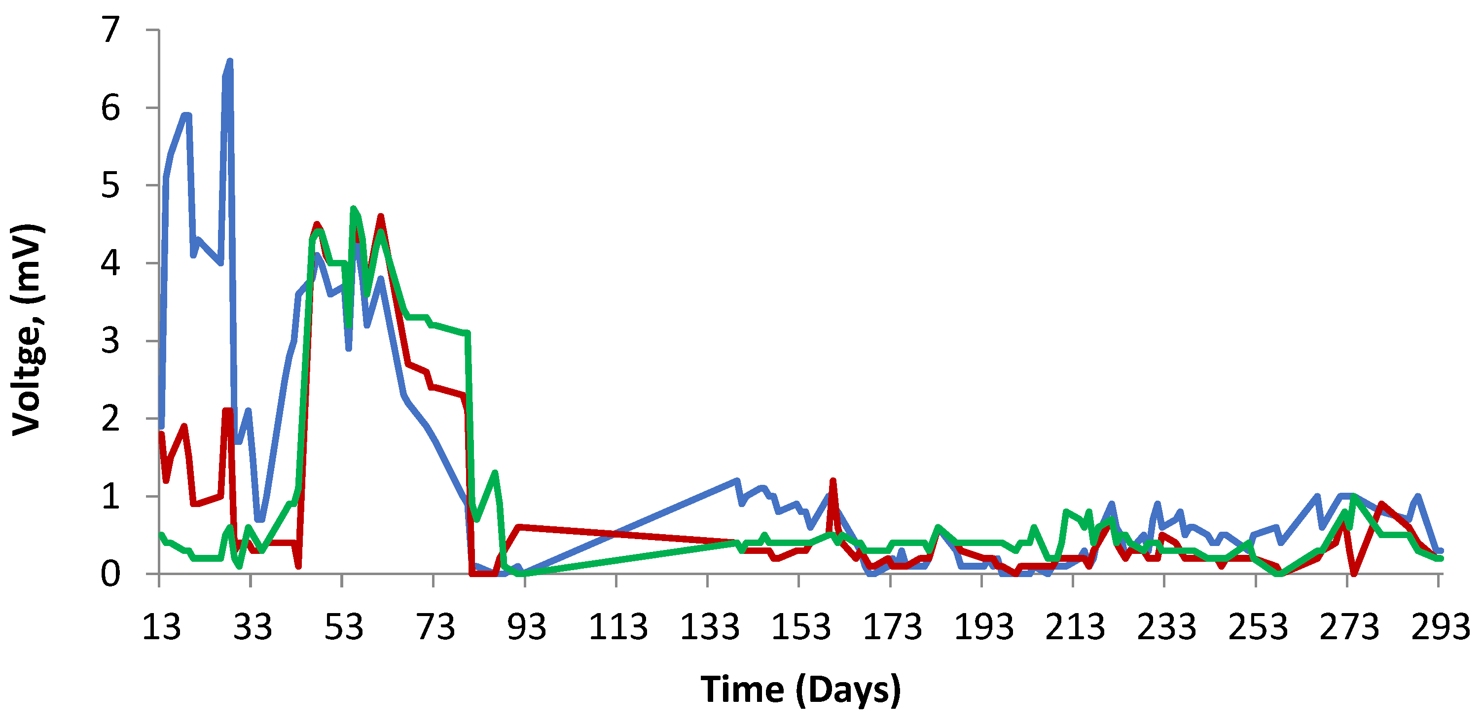
The electric current produced by the MFC system was calculated employing the generated voltage and an external resistance value of 1000 Ohms. The computed current levels fell below 1 mA, with an average value in the stabilized period of 0.2 mA. Although these are low current values, it is important to consider that the process under study is basically a wastewater treatment technology that, when compared to similar non-energy-producing technologies, is advantageous. The power density for the 10 individual cells of the MFC was calculated using the obtained voltage and current; Figure 5 shows that in the first unstable days of the experiment, the power reached up to 6 mW/m3. When the operation achieved a stabilized phase after a long time (after 150 days), the power decreased to near 0.0.5 mW/m3 on average, showing a maximum value of 1 mW/m3 and a minimum close to zero (in all cases, power density values were calculated with reference to the volume of the anode). The reasons for the variations in the individual values in power density were not clear at this time but could be related to the positions of anodes and cathodes as well as the regime flux. These values, however, are in the order of previous measurements obtained using laboratory-scale prototypes with similar configurations (about 0.1 W/m3) [14]. As a reference for the power generated, a comparison can be made with other studies. In a pilot system consisting of microbial fuel cells with a parallel-plate configuration and a total volume of 850 L, an average power density of 540 mW/m3 was reported [29], while a 1.5 m3 microbial electrochemical system achieved 406 mW/m3 [32]. In our system, the power density is approximately 7 mW/m3, which later decreases to values below 1 mW/m3, which can be attributed to the cell configuration, which is primarily designed as a wastewater treatment system. Its lower energy generation capacity is due to losses associated with the electrode arrangement and, more generally, with the cell design. In this context, our system can be better regarded as a wastewater treatment technology.
As shown in Figure 2, the COD removal increases and is maintained in general up to the end of the experiment, whereas the power output (Figure 5) tends to decline. This behavior is attributed to the fact that for microbial fuel cells (MFCs) employing three-dimensional (3D) porous anodes, the development of thick biofilms often results in microbial stratification, wherein electrogenic activity becomes confined to the inner layers. Under these conditions, the outer biofilm layers impose mass transport limitations and promote the accumulation of metabolic by-products, thereby increasing internal resistance and impeding electron transfer. Over extended operation, biofilms physically fragment, disrupting the electrical connectivity between electroactive microorganisms and the electrode surface. This loss of electrochemical continuity is reflected as a gradual decline in voltage and power output, despite the persistence of organic matter degradation [33,34].

3. Materials and Methods

3.1. PAML-MFC

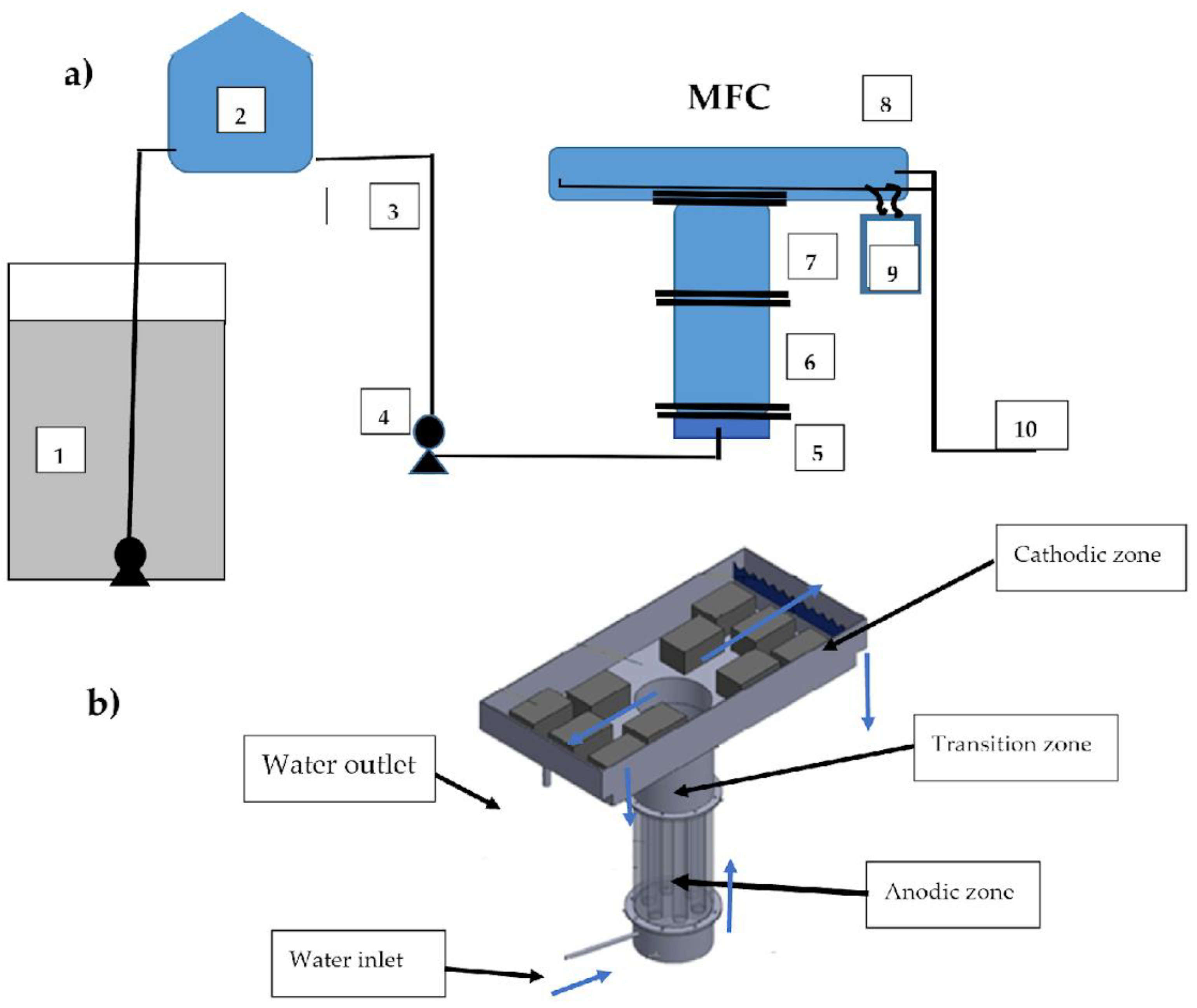
The experimental system in Figure 6a,b consists of a feed pit, an elevated tank, and a vertical pilot-scale PAML-MFC that was fed real wastewater produced by offices and laboratories in a research center in Mexico (Cideteq). A centrifugal pump sends the wastewater from the pit (1) to an elevated 250 L tank (2) that feeds the MFC through a 1-inch-diameter PVC pipe (3) and a peristaltic pump (4). The microbial fuel cell was built with an inlet (5) and an anodic (6) zone at the bottom, a transition zone between the anode and the cathode (7), and a cathodic zone at the top of the cell (8).
The anodic region (6) consisted of a cylindrical section characterized by a diameter of 80 cm and a height of 80 cm. Inside this zone, 10 PVC individual pipes (10 cm in diameter and 80 cm in height) were vertically placed and connected to the inlet (5) and transition zone (7), in which the wastewater flowed upwards. In these tubes, activated carbon was placed as an anode material up to a height of 60 cm; this carbon supports biomass growth. Considering the height of the carbon bed and the diameter of the vertical tubes in which the material was placed, each anode had a volume of 0.0047 m3, resulting in a total volume of 0.047 m3 for the ten anodes used in the system. In this anodic zone, the removal of organic contaminants—i.e., COD removal—takes place through the action of microorganisms attached to the surface of the activated carbon electrode.
The transition zone (7) was designed to preserve the anaerobic conditions of the anodic zone and was built using a similar 80 cm diameter circular section that was 50 cm tall (0.25 m3). This section was designed to create a space between the anode chamber and the upper part of the water in the cell, which is exposed to ambient air, in order to prevent the incorporation of large amounts of oxygen into the anodes.
The cathodic zone (8) consisted of a rectangular box (200 cm × 120 cm x 40 cm) with an arrangement of 10 individual rectangular containers (40 cm × 25 cm × 20 cm) that were filled with activated carbon. Each of the activated carbon cathodes had a volume of 0.02 m3, resulting in a total cathode volume of 0.2 m3. The cathodic zone has a larger cross-sectional area than the anodic zone in order to maximize exposure to ambient air, as the oxygen required for the cathodic reaction is supplied through direct transfer from the surrounding atmosphere. As shown in Figure 6a,b, the exposed area of the zone containing the cathodes is significantly larger than the area of the vertical column corresponding to the anodic zone.
The electrical connection between the anode and the cathode was made using a copper wire immersed in three-dimensional electrodes made of activated carbon. The connections of the wires were concentrated on a control board, where the voltage was measured (9). Supplementary information is provided in Figures S1–S3.
Wastewater is fed at the bottom of the PAML-MFC, as can be seen in the scheme in Figure 6a,b, flowing inside the ten individual anodes to reach the transition and, later, the cathodic zone. The water flowing through the cathode area is conducted to a screen where the effluent leaves the reactor in an outlet made of a 1 in diameter PVC pipe (10). The wastewater hydraulic flow was calculated to ensure a hydraulic retention time of 1 day.

3.2. Inoculation

The PAML-MFC was inoculated using mud from an anaerobic lagoon with a VSS concentration of 1000 mg/L. The inoculation in the anode was carried out by placing 10 cm of activated carbon and then 1 L of the indicated biomass. This procedure was repeated until a height of 60 cm was reached, and then 10 L of sludge was added to each anode.

3.3. Analytical Methods

The efficiency of the PAML-MFC system was calculated using the APHA method 5220D to determine the soluble COD content in the influent and in the effluent. For this purpose, each sample was filtered through a 0.45 mm filter (Whatman, Maidstone, UK) and digested using a Hach digester reactor (2 h at 150 °C). Then, COD was calculated by measuring the absorbance at 600 nm with a DR 6000 (Hach, Loveland, CO, USA) spectrometer. pH was determined in the influent and effluent using a Thermo Orion 4-Star Plus pH meter (Fisher Scientific, Pittsburgh, PA, USA), and the generated voltage was measured using a Truper 10401 MUT-33 multimeter (Truper, Mexico City, Mexico). The concentration of dissolved oxygen in and temperature of the water contained in the cathodic zone were obtained using an Orion 4567 dissolved oxygen and temperature meter (Orion, Espoo, Finland).

4. Conclusions

Tests conducted on a passive aerated membraneless pilot-scale microbial fuel cell show that this technological approach can be efficient for the treatment of 1000 L/day of real wastewater. The system under study reached COD removal values of 60–80% when the system stabilized. Despite the variations in wastewater characteristics, the incoming COD was 500 mg/L on average with a pH close to neutrality (6), allowing the cell to properly work for a few months. In addition, the 22 C average temperature is a permissible value for the development of biological processes. At the end of the cell’s operational period, after 160 days, the voltage generated ranged between 100 and 300 mV, while the power output remained below 1 mW/m3. In summary, it can be said that this technology could be used as a small-scale treatment system to remove organic contaminants from wastewater.

Supplementary Materials

The following supporting information can be downloaded at: https://www.mdpi.com/article/10.3390/catal15080765/s1. Figure S1. Overview of the membrane-less microbial fuel cell. Figure S2. Top view of the anode chamber showing the 10 compartments where the granular activated carbon anodes were placed. Figure S3. Top view of the anode chamber showing the three-dimensional activated carbon electrode. Figure S4. Box plot of COD removal efficiency (%) from day 119 to day 204. Figure S5. Probability distribution function of COD removal efficiency (%).

Author Contributions

Conceptualization, F.J.R.-V. and C.H.-B.; methodology, Z.A.J.; validation, C.H.-B. and V.R.; formal analysis, I.R.G.; investigation, Z.A.J. and V.R.; resources, I.R.G. and F.J.R.-V.; data curation, V.R. and F.J.R.-V.; writing—original draft preparation, Z.A.J. and V.R.; writing—review and editing, L.A.G. and F.J.R.-V.; visualization, V.R.; supervision, C.H.-B. and F.J.R.-V.; project administration, F.J.R.-V.; funding acquisition, F.J.R.-V. All authors have read and agreed to the published version of the manuscript.

Funding

This research was funded by Consejo Nacional de Ciencia y Tecnología (CONACYT), grant number 2015-01-1217 (the main national program grants).

Data Availability Statement

The original contributions presented in this study are included in the article/Supplementary Material. Further inquiries can be directed to the corresponding author.

Acknowledgments

ZAJ acknowledges CONACYT for a graduate fellowship.

Conflicts of Interest

The authors declare no conflicts of interest.

References

  1. Sonune, A.; Ghate, R. Developments in wastewater treatment methods. Desalination 2004, 167, 55–63. [Google Scholar] [CrossRef]
  2. Yoshizawa, T.; Miyahara, M.; Kouzuma, A.; Watanabe, K. Conversion of activated-sludge reactors to microbial fuel cells for wastewater treatment coupled to electricity generation. J. Biosci. Bioeng. 2014, 118, 533–539. [Google Scholar] [CrossRef]
  3. Gude, V.G. Wastewater treatment in microbial fuel cells—An overview. J. Clean. Prod. 2016, 122, 287–307. [Google Scholar] [CrossRef]
  4. Asai, Y.; Miyahara, M.; Kouzuma, A.; Watanabe, K. Comparative evaluation of wastewater-treatment microbial fuel cells in terms of organics removal, waste-sludge production, and electricity generation. Bioresour. Bioprocess. 2017, 4, 1–8. [Google Scholar] [CrossRef]
  5. Sarranyadhevi, D.; Shanmugasundaram, T.; Thirumalairaj, J.; Balagurunathan, R. Microbial fuel cells: An Actinobacterial Mediated Novel Approach For Power Generation. J. Appl. Microbiol. 2014, 3, 45–53. [Google Scholar]
  6. Du, Z.; Li, H.; Gu, T. A state of the art review on microbial fuel cells: A promising technology for wastewater treatment and bio-energy. Biotechnol. Adv. 2007, 25, 464–482. [Google Scholar] [CrossRef] [PubMed]
  7. Choudhury, P.; Uday, U.S.P.; Mahata, N.; Tiwari, O.N.; Ray, R.N.; Bandyopadhyay, T.K.; Bhunia, B. Performance improvement of microbial fuel cells for wastewater treatment along with value addition: A review on past achievements and recent perspectives. Renew. Sustain. Energy Rev. 2017, 79, 372–389. [Google Scholar] [CrossRef]
  8. Gajda, I.; Greenman, J.; Ieropoulos, I. Recent advancements in real-world microbial fuel cell applications. Curr. Opin. Electrochem. 2018, 11, 78–83. [Google Scholar] [CrossRef] [PubMed]
  9. Rodrigo, M.A.; Cañizares, P.; Lobato, J.; Paz, R.; Sáez, C.; Linares, J.J. Production of electricity from the treatment of urban waste water using microbial fuel cell. J. Power Sources 2007, 169, 198–204. [Google Scholar] [CrossRef]
  10. Guo, Y.; Wang, J.; Shinde, S.; Wang, X.; Li, Y.; Dai, Y.; Ren, J.; Zhang, P.; Liu, X. Simultaneous wastewater treatment and energy harvesting in microbial fuel cells: An update on the biocatalyst. RSC Adv. 2020, 10, 25874–25887. [Google Scholar] [CrossRef]
  11. Rahimnejad, M.; Adhami, A.; Darvari, S.; Zirepour, A.; Oh, S. Microbial fuel cell as new technology for bioelectricity generation: A review. Alexandria. Eng. J. 2015, 54, 745–756. [Google Scholar] [CrossRef]
  12. Sirinutsomboon, B. Modeling of a membraneless single-chamber microbial fuel cell with molasses as an energy source. Int. J. Energy Environ. Eng. 2014, 5, 1–9. [Google Scholar] [CrossRef]
  13. Thung, W.; Ong, S.; Ho, L.; Wong, Y.; Oon, Y.L.; Oon, Y.S.; Lehl, H. Simultaneous Wastewater Treatment and Power Generation with Innovative Design of an Upflow Membrane-Less Microbial Fuel Cell. Water Air Soil Pollut. 2015, 226, 1–7. [Google Scholar] [CrossRef]
  14. Jiménez, M.L.; Hernández, C.; Juárez, Z.; Zamudio, E.; Ramírez, V.; Robles, I.; Godínez, L.A.; Rodríguez-Valadez, F. Study of the Effect of Activated Carbon Cathode Configuration on the Performance of a Membrane-Less Microbial Fuel Cell. Catalysts 2020, 10, 619. [Google Scholar] [CrossRef]
  15. Hiegemann, H.; Herzer, D.; Nettmann, E.; Lübken, M.; Schulte, P.; Schmelz, K.G.; Gredigk-Hoffmann, S.; Wichern, M. An integrated 45 L pilot microbial fuel cell system at a full-scale wastewater treatment plant. Bioresour. Technol. 2016, 218, 115–122. [Google Scholar] [CrossRef] [PubMed]
  16. Valladares, R.; Domínguez-Maldonado, J.; Rodríguez-Leal, E.; Patrón, G.; Castillo-Hernández, A.; Miranda, A.; Díaz, D.; Moreno-Cervera, R.; Camara-Chale, G.; Borroto, C.; et al. Scale up of Microbial Fuel Cell Stack System for Residential Wastewater Treatment in Continuous Mode Operation. Water 2019, 11, 217. [Google Scholar] [CrossRef]
  17. Nakhate, P.; Patil, H.G.; Shah, V.; Salvi, T.; Marathe, K. Process validation of integrated bioelectrochemical and membrane reactor for synchronous bioenergy extraction and sustainable wastewater treatment at a semi-pilot scale. Biochem. Eng. J. 2019, 151, 107309. [Google Scholar] [CrossRef]
  18. Srivastava, P.; Abbassib, R.; Garaniya, V.; Lewis, T.; Yadav, A.K. Performance of pilot-scale horizontal subsurface flow constructed wetland coupled with a microbial fuel cell for treating wastewater. J. Water Process Eng. 2020, 33, 100994. [Google Scholar] [CrossRef]
  19. Tang, C.; Zhao, Y.; Kang, C.; Yang, Y.; Morgan, D.; Xu, L. Towards concurrent pollutants removal and high energy harvesting in a pilot-scale CW-MFC: Insight into the cathode conditions and electrodes connection. Chem. Eng. J. 2019, 373, 150–160. [Google Scholar] [CrossRef]
  20. Tota-Maharaj, K.; Parneet, P. Performance of pilot-scale microbial fuel cells treating wastewater with associated bioenergy production in the Caribbean context. Int. J. Energy Environ. Eng. 2015, 6, 213–220. [Google Scholar] [CrossRef]
  21. Vilajeliu-Pons, A.; Puig, S.; Salcedo-Dávila, I.; Balaguer, M.D.; Colprim, J. Long-term assessment of six-stacked scaled-up MFCs treating swine manure with different electrode materials. Environ. Sci. Water Res. Technol. 2017, 3, 947–959. [Google Scholar] [CrossRef]
  22. Wu, S.; Li, H.; Zhou, X.; Liang, P.; Zhang, X.; Jiang, Y.; Huang, X. A novel pilot-scale stacked microbial fuel cell for efficient electricity generation and wastewater treatment. Water Res. 2016, 98, 396–403. [Google Scholar] [CrossRef]
  23. Li, B.; Scheible, K.; Curtis, M. Electricity Generation from Anaerobic Wastewater Treatment in Microbial Fuel Cells; Water Environment Research Foundation: Alexandria, VA, USA; New York State Energy Research and Development Authority: Albany, NY, USA, 2011. [Google Scholar]
  24. Hsu, L.; Arias-Thodea, M.; Salvacion, M.; Benavidez, Z.; Mirhosseini, A.; Babanova, S.; Chen, S.; Bretschger, O. Demonstration of an Energy-Neutral, Off-Grid Microbial Fuel Cell System for Decentralized Wastewater Treatment. ECS Trans. 2017, 75, 19–29. [Google Scholar] [CrossRef]
  25. Dong, Y.; Qu, Y.; He, W.; Du, Y.; Liu, J.; Han, X. A 90-liter stackable baffled microbial fuel cell for brewery wastewater treatment based on energy self-sufficient mode. Bioresour. Technol. 2015, 195, 66–72. [Google Scholar] [CrossRef]
  26. Feng, Y.; He, W.; Liu, J.; Wang, X.; Qu, Y.; Ren, N. A horizontal plug flow and stackable pilot microbial fuel cell for municipal wastewater treatment. Bioresour Technol. 2014, 156, 132–138. [Google Scholar] [CrossRef]
  27. Liang, P.; Duan, R.; Jiang, Y.; Zhang, X.; Qiu, Y.; Huang, X. One-year operation of 1000-L modularized microbial fuel cell for municipal wastewater treatment. Water Res. 2018, 141, 1–8. [Google Scholar] [CrossRef]
  28. Du, F.; Li, Z.; Yang, S.; Xie, B.; Liu, H. Electricity generation directly using human feces wastewater for life support system. Acta Astronaut. 2011, 68, 1537–1547. [Google Scholar] [CrossRef]
  29. Rossi, R.; Hur, A.; Page, M.; O’Brien, A.; Butkiewicz, J.; Jones, D.; Baek, G.; Saikaly, P.; Cropek, D.; Logan, B. Pilot scale microbial fuel cells using air cathodes for producing electricity while treating wastewater. Water Res. 2022, 215, 118208. [Google Scholar] [CrossRef]
  30. Zhang, L.; Wang, R.; Li, H.; Sun, J.; Li, M.; Qiu, Y. Enhancing microbial fuel cell performance with free-standing three-dimensional N-doped porous carbon anodes. Chem. Eng. J. 2024, 500, 156807. [Google Scholar] [CrossRef]
  31. Puig, S.; Serra, M.; Coma, M.; Cabré, M.; Dolors, M.; Colprim, J. Effect of pH on nutrient dynamics and electricity production using microbial fuel cells. Bioresour. Technol. 2010, 101, 9594–9599. [Google Scholar] [CrossRef] [PubMed]
  32. He, W.; Dong, Y.; Li, C.; Han, X.; Liu, G.; Liu, J.; Feng, Y. Field tests of cubic-meter scale microbial electrochemical system in a municipal wastewater treatment plant. Water Res. 2019, 155, 372–380. [Google Scholar] [CrossRef] [PubMed]
  33. Sun, D.; Chen, J.; Huang, H.; Liu, W.; Ye, Y.; Cheng, S. The effect of biofilm thickness of Geobacter sulfurreducens. Int. J. Hydrogen Energy. 2016, 41, 16523–16528. [Google Scholar] [CrossRef]
  34. Hu, Y.; Wang, Y.; Han, X.; Shan, Y.; Li, F.; Shi, L. Biofilm biology and engineering of Geobacter and Shewanella spp. for energy applications. Front. Bioeng. Biotechnol. 2021, 9, 786416. [Google Scholar] [CrossRef] [PubMed]
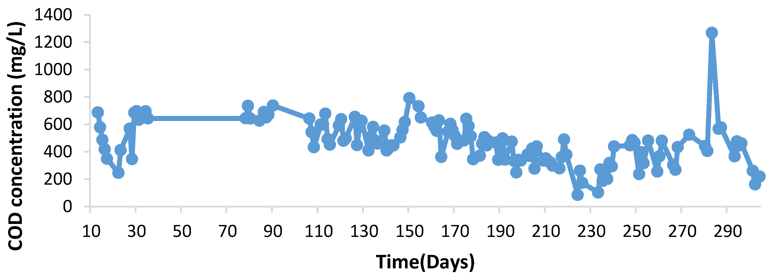
Figure 1. COD of the water fed to the MFC.
Catalysts 15 00765 g001
Figure 2. COD removal efficiency of the MFC. The vertical lines indicate the days on which electrode cleaning was performed.
Catalysts 15 00765 g002
Figure 3. Experimental variables obtained for PAML-MFC during the stabilized phase, (a) pH measured in the inlet water, (b) temperature in the cathodic section, (c) dissolved oxygen in the cathodic section.
Catalysts 15 00765 g003
Figure 4. Representative voltage generated in 3 of the 10 individual MFCs (mV). Electrode 1 (blue), electrode 3 (red), electrode 4 (green).
Catalysts 15 00765 g004
Figure 5. Representative power density generated in 3 of the 10 individual MFCs (W/m3). Electrode 1 (blue), electrode 3 (red), electrode 4 (green).
Catalysts 15 00765 g005
Figure 6. PAML-MFC arrangement: (a) complete experimental installation, (1) pit, (2) elevated tank, (3) PVC pipe, (4) peristaltic pump, (5) MFC inlet zone (6) MFC anodic zone, (7) MFC transition zone, (8) MFC cathodic zone, (9) control board, (10) outlet water pipe; (b) MFC details and water circulation. The blue lines indicate the direction of the wastewater flow.
Catalysts 15 00765 g006
Disclaimer/Publisher’s Note: The statements, opinions and data contained in all publications are solely those of the individual author(s) and contributor(s) and not of MDPI and/or the editor(s). MDPI and/or the editor(s) disclaim responsibility for any injury to people or property resulting from any ideas, methods, instructions or products referred to in the content.