Article

Analysis and Application of UV-LED Photoreactors for Phenol Removal

by
Betsabé Ildefonso-Ojeda
1,
Macaria Hernández-Chávez
1,
Mayra A. Álvarez-Lemus
2,
Rosendo López-González
2,
José R. Contreras-Bárbara
3,
Karen Roa-Tort
1,
Josué D. Rivera-Fernández
1 and
Diego A. Fabila-Bustos
1,*
1
Laboratorio de Optomecatrónica y Energías, Unidad Profesional Interdisciplinaria de Ingeniería Campus Hidalgo (UPIIH), Instituto Politécnico Nacional, Distrito de Educación, Salud, Ciencia, Tecnología e Innovación, San Agustín Tlaxiaca 42162, Mexico
2
Nanotechnology Laboratory, Academic Division of Engineering and Architecture, Juarez Autonomous University of Tabasco, Carr. Cunduacán Jalpa de Méndez Km. 1, Col. La Esmeralda, Cunduacán 86690, Mexico
3
Unidad Profesional Interdisciplinaria de Ingeniería Campus Palenque (UPIIP), Instituto Politécnico Nacional, Carretera Palenque-Pakal-Ná, Km. 2.5, Col. Centro, Palenque 29960, Mexico
*
Author to whom correspondence should be addressed.
Catalysts 2025, 15(8), 748; https://doi.org/10.3390/catal15080748
Submission received: 14 June 2025 / Revised: 1 August 2025 / Accepted: 4 August 2025 / Published: 5 August 2025
(This article belongs to the Special Issue Remediation of Natural Waters by Photocatalysis)

Abstract

The development of three types of UV radiation-based photoreactors using light-emitting diodes (LEDs) is presented. In this work, three pattern irradiation arrangements, direct radiation, internal radiation, and external radiation, were tested for deactivation of a typical model contaminant in wastewater under the same conditions. All photoreactors allow the adjustment of optical power and irradiation time and include a sensor for temperature monitoring in the solution. In this case, phenol was used as a model contaminant with TiO2 as a photocatalyst in a batch-type reactor at pH 7. The results showed that the highest degradation efficiency was achieved after 120 min, reaching 97.79% for the internal-radiation photoreactor, followed by 90.17% when the direct-radiation photoreactor was used, and 85.24% for the external-radiation photoreactor. Phenol degradation served as the basis for validating reactor performance, given its persistence and relevance as an indicator in advanced oxidation processes. It was concluded that the arrangement of LEDs in each photoreactor significantly influences phenol degradation under the same reaction conditions.

1. Introduction

Phenolic compounds are benzene derivatives which possess one or more hydroxyl groups attached to the aromatic ring. They are distinguished by their sweet, penetrating odor and high flammability [1]. Due to these properties, phenols have wide industrial applications, including the production of dyes, plastics, resins, and, in some cases, sanitizers. However, their presence in wastewater becomes an environmental problem as phenol is a semivolatile hydrocarbon that can be found in varying concentrations ranging from 1 mg/L to 7000 mg/L [2]. The environmental impact of phenol is attributed to its high toxicity. Concentrations between 10 and 24 mg/L can be harmful to humans, while toxic levels for fish range from 9 to 25 mg/L [3]. Its rapid absorption through the skin and mucous membranes makes it hazardous to the nervous system, heart, kidneys, and liver [4]. Consequently, various strategies have been developed for its removal from water, combining conventional and advanced methods. These methods include extraction, adsorption, electrocoagulation, polymerization, biological processes, electro-Fenton, ion exchange, membrane separation, and advanced oxidation processes (AOPs) [5].
Among these methods, advanced oxidation processes have gained significant attention for their efficiency in degrading phenols [6]. During the last years, heterogeneous photocatalysis with TiO2 and ultraviolet radiation has emerged as a promising alternative for eliminating persistent organic pollutants, generating less toxic and more biodegradable products that can eventually mineralize into carbon dioxide and water [7,8]. Therefore, photoreactors have been developed as adaptable systems for photodegrading organic compounds through photocatalysis, typically requiring light sources with wavelengths between 250 and 385 nm, including both solar radiation and artificial sources such as mercury-vapor lamps [9]. While there is a growing interest in shifting towards visible and solar light sources to enhance sustainability, the choice of light is strongly dependent on the photocatalyst’s activation range. Mercury-vapor lamps present significant challenges such as high energy consumption, mercury toxicity, and short lifespan. To overcome these limitations, the use of LEDs has been proposed and studied as a more efficient and sustainable alternative [10]. Compared to conventional lamps, LEDs offer advantages such as wavelength specificity, greater durability, compact size, long lifespan, a relatively cool emitting surface, a linear photon output with electrical current input, and the ability to control radiant flux [11,12]. These characteristics enable more flexible reactor designs and enhance the efficiency of photocatalytic processes, as LEDs do not require a warm-up period like traditional lamps [13]. Furthermore, multiple studies have documented the development of LED-based photoreactors, demonstrating that high-power LEDs represent more cost-effective and efficient options [14]. This study especially addresses the current state of the art on the application of 365 nm UV-LEDs for the photocatalytic degradation of phenol, a topic that remains highly relevant due to the environmental persistence of phenolic compounds. Furthermore, multiple studies have documented the development of LED-based photoreactors for several applications. Dai et al. proposed a square UV-LED photoreactor based on 504 LEDs emitting at 376 nm, with 126 LEDs on each side. The system was tested for the degradation of methylene blue (MB), demonstrating that photodegradation increases when pH is below 4.16. However, a rise in temperature negatively affects system performance [15]. Ferreira et al. proposed a novel home-lab prototype combining UVA-LEDs and a resonant inductive coupling (RLC) system; the latter was employed to increase the UV photon absorption. The prototype includes 14 LEDs. The system was tested in four types of agro-industrial wastewater, achieving the best results when the resonant frequency was set to 26.8 kHz. However, although energy efficiency varied, total energy consumption remained high, indicating that both the RLC module and the number of LEDs should be optimized [16]. On the other hand, Nyangaresi et al. conducted a study where they used UV-LEDs at four wavelengths (265, 275, 310, and 365 nm) to compare the disinfection action of E. coli using photolysis and photocatalysis with TiO2. In this case, they used a small matrix of LEDs to irradiate directly a 60 mm Petri dish. The results obtained show a higher inactivation when wavelengths of 265 and 275 nm are used without TiO2; however, its inclusion slowly diminished the effect. Nevertheless, when 1.0 g of TiO2 was used at wavelengths of 310 and 365 nm, a significant improvement was achieved for inactivation efficiency [17]. Triquet et al. developed a TiO2 layer, deposited by MOCVD onto the optical window of a microreactor, illuminated with 365 nm UV-LEDs, eliminating the need for P25 TiO2 powder and simplifying catalyst recovery. The results show that the TiO2 coating significantly improved the reaction rate compared to untreated substrates [18]. Schwarse et al. reported complete phenol degradation and 70% mineralization after 3 h using immobilized commercial TiO2 and LED sources. These findings reinforce the relevance of exploring 365 nm UV-LED systems, not only as energy-efficient alternatives but also as effective platforms for pollutant removal [19]. On the other hand, although previous research has shown promising results using TiO2-based catalysts under 365 nm irradiation, they did not review the effects of irradiation configuration of emitted light, which is relevant for a better photocatalytic effect. In this sense, we evaluated three photoreactors equipped with high-power LEDs emitting light at a wavelength of 365 nm for their effectiveness in the removal of phenol in aqueous solution. Different photoreactor configurations were proposed for the photocatalytic degradation process, taking advantage of the efficiency and compactness of LED-based UV systems.

2. Results and Discussion

2.1. Photoreactors

In Figure 1, we present a representative photograph of each photoreactor. In this case, we used an arbitrary molecule to represent the operation of the photoreactors. The systems have an LCD interface for user configuration, and on this screen, temperature and irradiation time are displayed after the experiment starts. Moreover, all systems are equipped with a security door that blocks any light leakage for user safety. It is also programmed to automatically shut off the system if the door is opened unexpectedly. The images correspond to the following configurations: Figure 1a, the Direct Radiation Photoreactor (DRP); Figure 1b, the Internal Radiation Photoreactor (IRP); and Figure 1c, the External Radiation Photoreactor (ERP). For the capture of these images, the system was temporarily adjusted, always taking care of the safety of the user by using protective glasses and skin protection.

2.2. Photocatalytic Evaluation

Figure 2 shows the reactor containing the solution under UV lamp irradiation (Figure 2a) and photoreactor irradiation (Figure 2b–d). The solution temperature remained between 24 and 29 °C for the UV lamp, 25–26 °C for the DRP, 25–26 °C for the IRP, and 23–24 °C for the ERP. The use of aluminum foil to cover the system enhances the efficiency of contaminant molecule removal [20]. Additionally, air bubbling introduces oxygen into the system through microbubbles, which dissolve in the solution and act as an essential source of dissolved oxygen. In the presence of light, water, and a photocatalyst, they contribute to the generation of reactive oxygen species (ROS), which drive the degradation of phenol. This enhancement of oxygen availability and mass transfer makes bubbling a widely used method in photocatalytic processes [21]. While ROS formation was not directly verified in this study, the observed degradation efficiency aligns with mechanisms reported in the literature under similar conditions [22,23,24,25]. However, the proposed degradation pathway is supported by previous studies that used TiO2 under similar conditions, where OH and O2•− were confirmed to be the main oxidative species through scavenger assays [26].
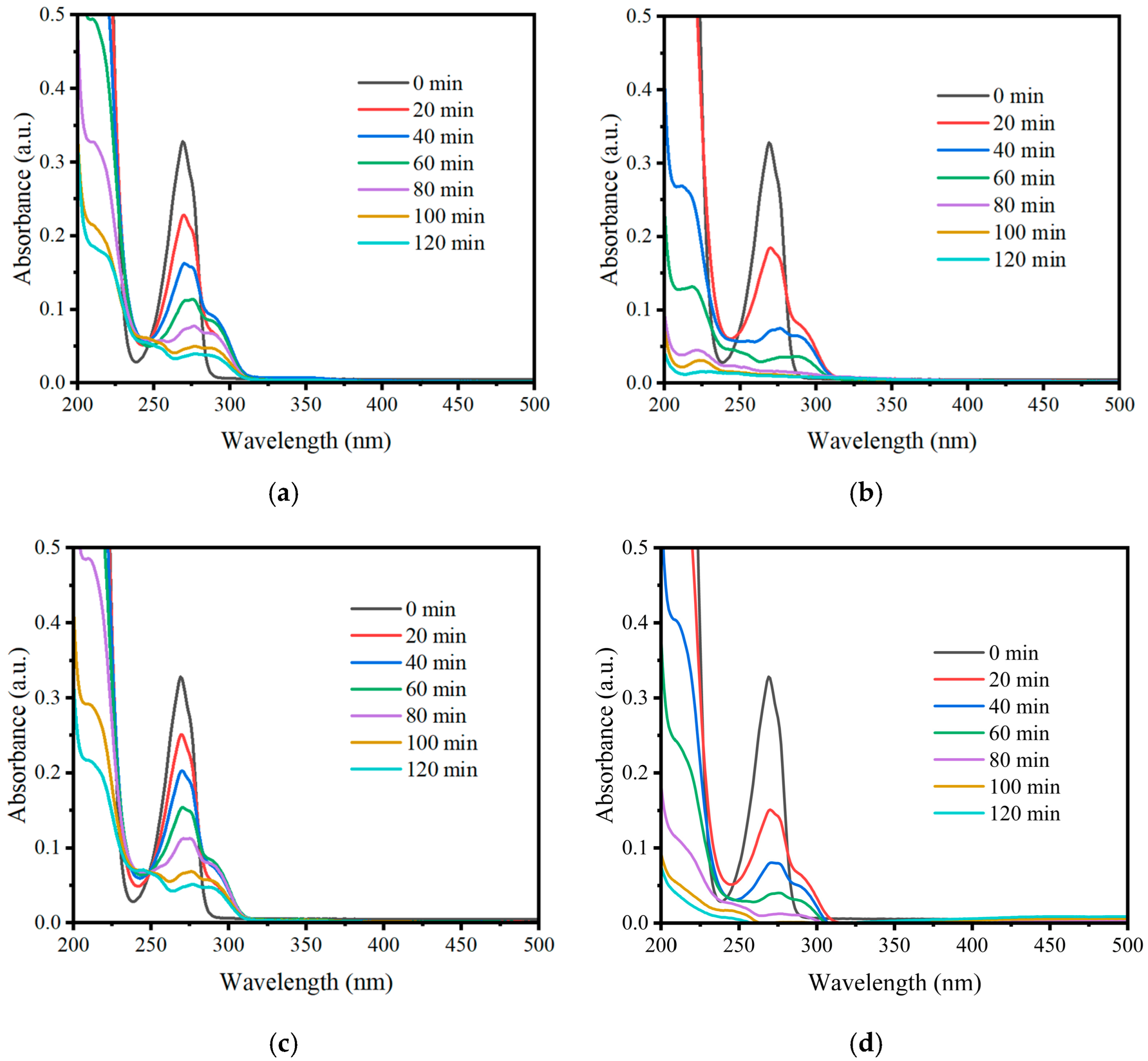
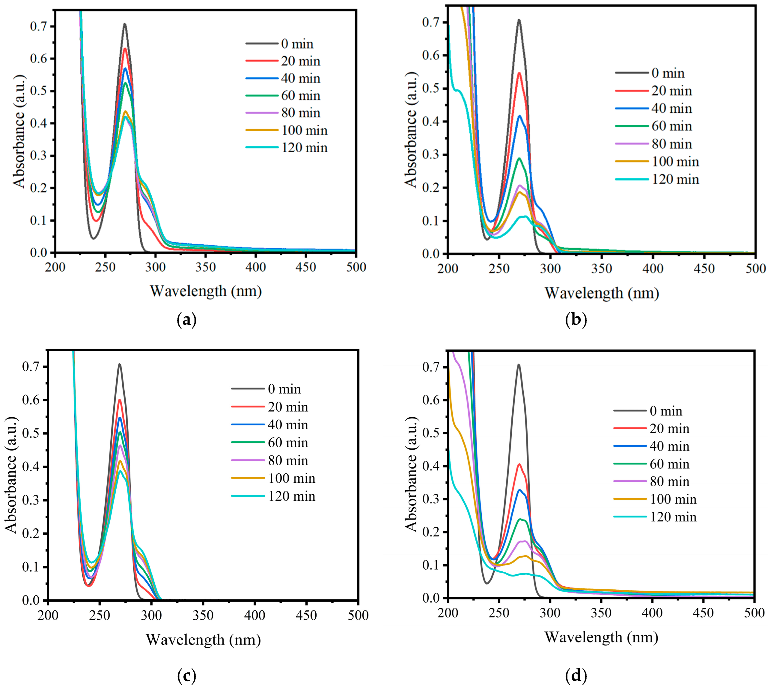
The evolution of the UV–Vis absorption spectrum during phenol photodegradation revealed not only the progressive disappearance of the initial pollutant but also the formation of intermediate species. In all tested systems (DRP, IRP, and ERP) and under the UV lamp, the characteristic absorption peak of phenol at 269 nm showed a steady decrease with irradiation time, confirming its degradation.
Figure 3 and Figure 4 show the photocatalytic process—new signals emerge between 275 and 320 nm, mainly attributed to catechol (275–280 nm) and oxidized forms like benzoquinone (330–350 nm), showing that phenol is undergoing hydroxylation followed by oxidation [27,28]. In this range, hydroquinone (288 nm) or phenolate ion (287 nm) is also likely present as another typical intermediate [29]. A weaker signal is seen in the 245–250 nm range, which matches the secondary absorption of benzoquinone [6].
Around 260 nm, a notable decrease in absorbance occurs rather than a defined peak; this may be due to lower electron density or intermediate transitional species, possibly indicating the start of aromatic-ring opening [30]. It is important to note that the UV–Vis absorbance measurements at 269 nm may overestimate the remaining phenol concentration during the photodegradation process; this is due to the formation of aromatic intermediates such as catechol, hydroquinone, and resorcinol, which also absorb in this region and have similar molar absorptivity values to phenol. As a result, the calculated degradation efficiency might be slightly underestimated [31]. To understand this process, the degradation mechanism of phenol is presented below [30].
T i O 2 + h v e + h +
h + + H 2 O   O H + H +
h + + O H     O H
e + O 2   O 2
  O 2 + e + 2 H + H 2 O 2
  O 2 + 2 H 2 O   O H + O H + O 2
P h e n o l +   O H i n t e r m e d i a t e s C O 2 + H 2 O
At the final stages of phenol photodegradation for IRP, a clear signal appears at 225 nm, which is commonly associated with low-molecular-weight aliphatic compounds [32], likely formed through aromatic-ring cleavage, such as short-chain organic acids or aldehydes [33]. This supports degradation pathways involving hydroxylation, oxidation, and eventual molecular fragmentation and mineralization of phenol [34].
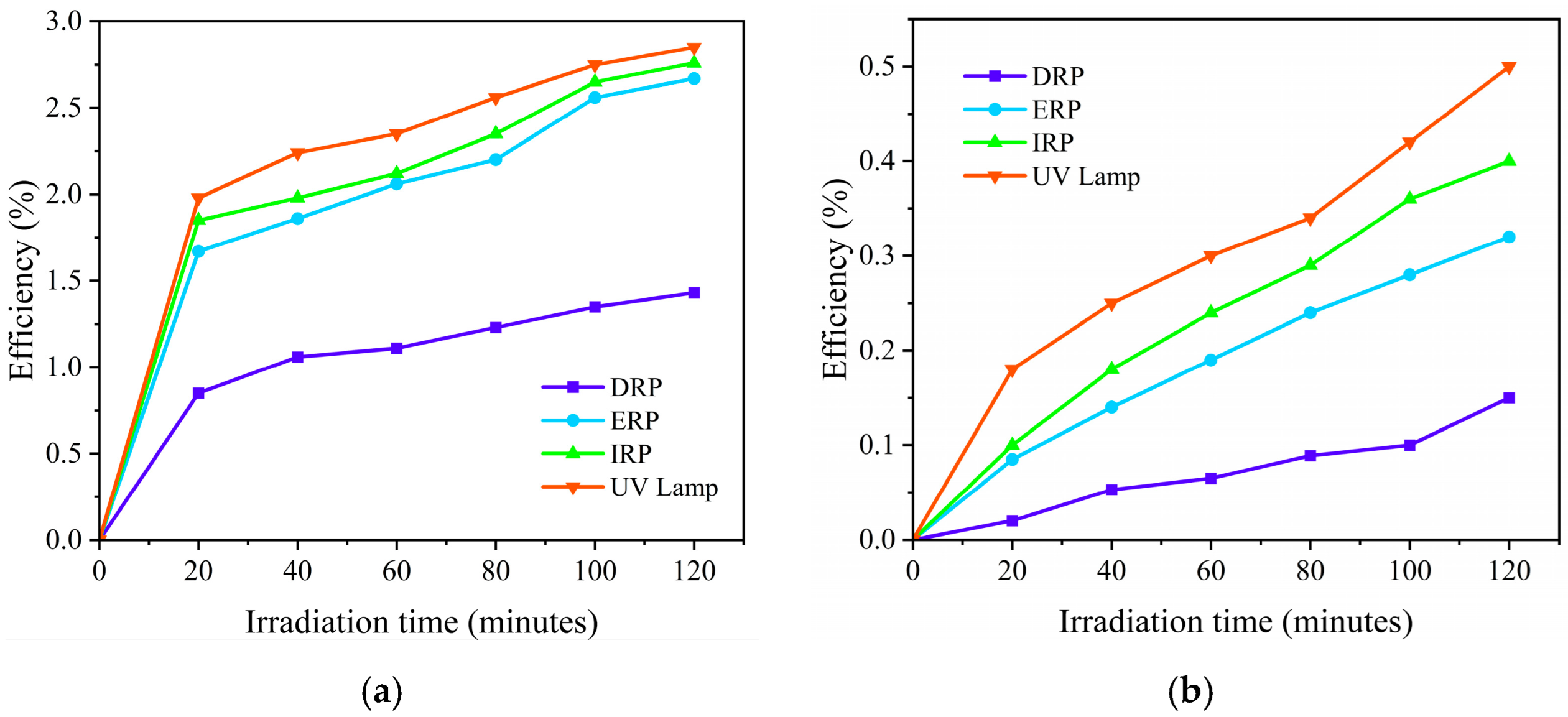
As shown in Figure 5a, when exposed only to UV light (photolysis) at an initial phenol concentration of 25 ppm, the removal efficiencies were 2.76% for the IRP system, 2.67% for the ERP, 1.43% for the DRP, and 2.85% for the UV lamp. At a higher concentration (50 ppm), the removal efficiencies decreased further, reaching only 0.40% for the IRP, 0.32% for the ERP, 0.15% for the DRP, and 0.38% for the UV lamp, as shown in Figure 5b. These values are considered negligible, confirming that photolysis alone is not sufficient for effective phenol degradation under the tested conditions.
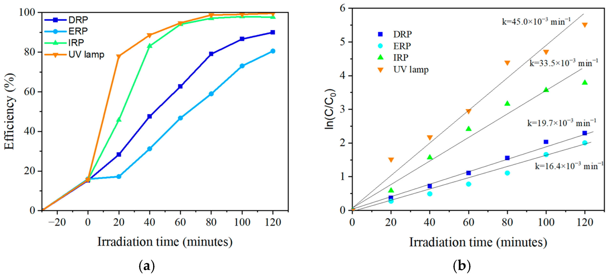
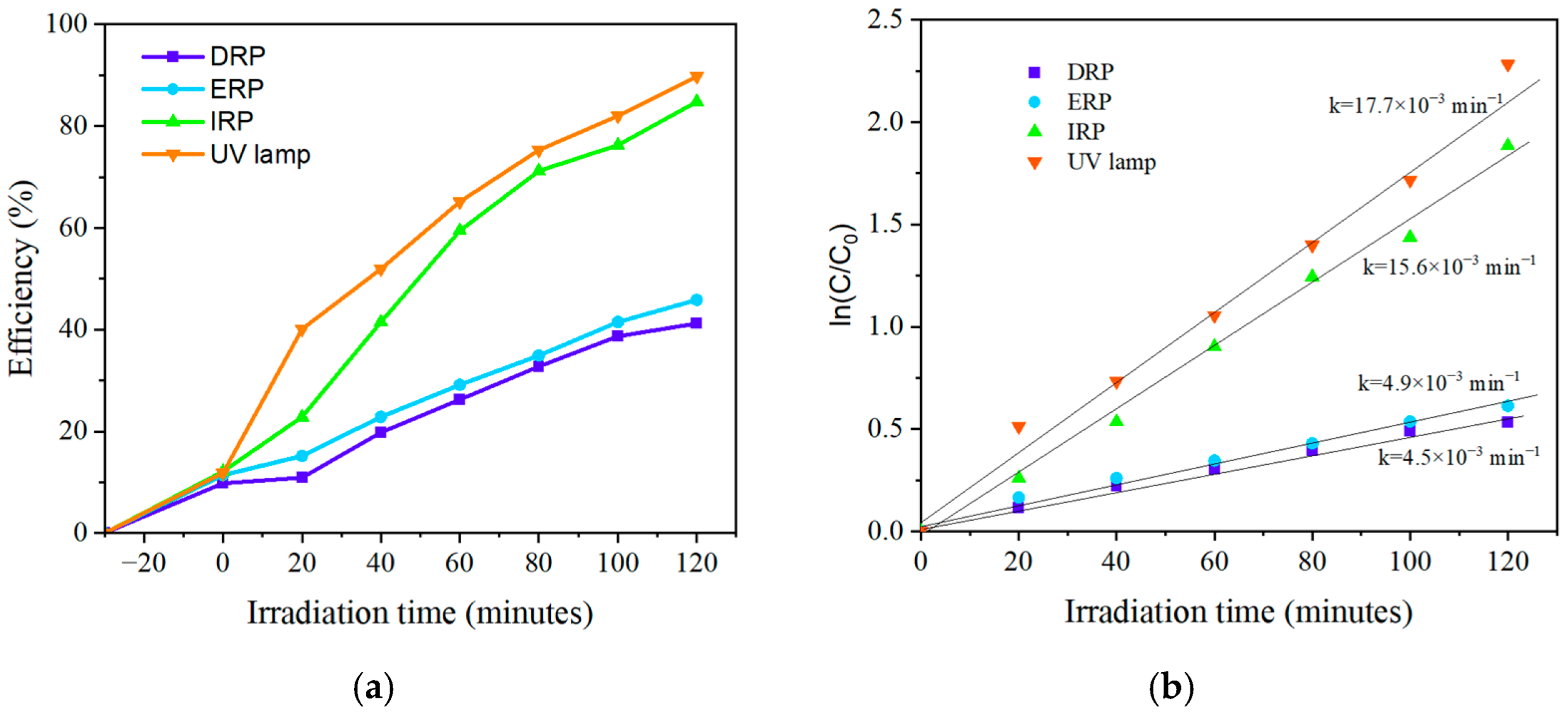
Preliminary tests indicated that the adsorption of phenol at 25 ppm on the photocatalyst material accounted for a removal efficiency of 15 ± 2%. Figure 6 presents the phenol photodegradation efficiency along with the reaction kinetics. The highest efficiency was reached at 120 min, with 97.79% for the IRP, followed by 90.17% for the DRP, 85.24% for the ERP, and 99.60% for the UV lamp. On the other hand, the photocatalytic degradation kinetics of phenol follow a pseudo-first-order kinetics, which is commonly applied in photocatalyst processes when the contaminant concentration is low and the number of active sites on the catalyst is assumed constant [35,36,37]. The k values obtained were as follows: IRP 33.5 × 10⁻³ min−1 (R2 = 0.96); DRP 19.7 × 10⁻³ min−1 (R2 = 0.99); ERP 16.4 × 10⁻³ min−1 (R2 = 0.97); and UV lamp 45.0 × 10⁻³ min−1 (R2 = 0.97).
For the adsorption of phenol at 50 ppm the removal efficiency was of 11.5 ± 2%. Figure 7, the efficiencies and kinetic behavior of the systems are presented. The highest efficiency was reached at 120 min, with 84.81% for IRP, followed by 41.21% for DRP, 45.83% for ERP and 89.80% for UV lamp. Regarding the reaction kinetics it also a pseudo-first-order behavior, with a rate constant, k, obtained for the IRP 15.6 × 10⁻³ min−1 (R2 = 0.98); DRP 4.5 × 10⁻³ min−1 (R2 = 0.98), ERP 4.9 × 10⁻³ min−1 (R2 = 0.98) and UV lamp 17.7 × 10⁻³ min−1 (R2 = 0.98).
These results show that both photodegradation efficiency and reaction rate decrease as phenol concentration increases [38]. This behavior is attributed to a possible to the partial saturation of active sites on the catalyst surface and greater competition for photon absorption [39]. The strong correlation coefficients (R2 > 0.96) support the validity of the kinetic model applied (Table 1). Furthermore, the highest efficiency obtained with the UV lamp can be attributed to higher irradiance and more uniform light distribution, which aligns with studies reporting a direct relationship between UV intensity and degradation kinetics [40].
Variations in the rate constants reflect differences in photon absorption efficiency and active site accessibility [34]. The higher rate constants observed for the UV lamp and IRP reactor indicate more efficient interactions between photons, the catalyst, and the pollutant, likely due to favorable irradiation and intensity [41,42]. In contrast, the lower rate constants for DRP and ERP suggest catalytic limitations, possibly arising from uneven light exposure, reduced catalyst activation, or configuration restrictions in reactor design [43,44]. The further decline in rate constants at 50 ppm supports the idea of catalyst surface saturation, which reduces reactive species generation and thus the overall catalytic activity [37].
The half-life time (t1/2) were calculated based on the pseudo-first-order rate constants obtained for each system (Table 2). A consistent increase in t1/2 (minutes) with increasing concentration is observed, indicating a reduction in degradation efficiency at higher pollutant loads [45]. This trend can be attributed to the saturation of active sites on the TiO2 surface and the limited availability of photons under constant irradiance [42]. Among all systems, DRP and ERP exhibited the steepest increase in t1/2, suggesting greater sensitivity to concentration changes. In contrast, UV lamp and IRP configurations maintained relatively low t1/2 values, demonstrating a more stable and efficient photocatalytic performance under varying conditions.
Several studies have evaluated the efficiency of titanium dioxide (TiO2) as a photocatalyst for the degradation of phenol under solar irradiation. Although the results are generally positive, they also reveal a strong dependence of performance on experimental conditions such as the type of doping, the addition of oxidizing agents, and the intensity of available solar radiation. For example, Martin et al. [46] conducted a study using TiO2 doped with cerium (0.1% nominal atomic concentration) combined with persulfate as an oxidant. Under natural sunlight conditions during the spring–summer season in La Plata, Argentina, they achieved complete degradation (100%) of a 250 µM phenol solution after 3 h of exposure.
In another approach, Chowdhury et al. [47] used TiO2 sensitized with the dye Eosin Y and loaded with 0.5% platinum. Using simulated solar light with a UV cut-off filter (λ > 420 nm), they were able to degrade 93% of phenol (at a concentration of 40 ppm) in just 90 min. These studies demonstrate that phenol photodegradation under solar light can reach high efficiency levels, but its performance strongly depends on factors such as the presence of dopants, oxidizing agents, and light intensity.
However, when these results are compared with those obtained using LED light sources, it becomes clear that LEDs offer significant advantages in terms of experimental control and reproducibility. Photodegradation assisted by LEDs can achieve similar or even superior efficiencies in a shorter time, without the need for complex cooling systems or mercury lamps. For instance, Belekbir et al. [48] reported an efficiency of 70% in 60 min, whereas in this study, 97.79% efficiency was achieved in just 120 min (Table 3).
Although only 100 mg of TiO2-P25 was used with two phenol concentrations, this dosage was chosen based on literature reports that identify it as optimal to maintain sufficient catalytic activity while avoiding excess turbidity, which can hinder light penetration and reduce photocatalytic efficiency [35,50]. In preliminary tests, higher catalyst loadings resulted in increased solution opacity without significantly improving degradation rates. Additionally, a 30 min dark adsorption phase was included prior to irradiation to ensure equilibrium between phenol and the catalyst surface, as recommended in photocatalytic studies, to distinguish true photocatalytic degradation from physical adsorption [37]. The use of UV-A light at 365 nm is consistent with the bandgap excitation of TiO2 and is widely applied in similar studies [34]. Continuous air bubbling was also employed throughout the experiments to supply dissolved oxygen, which acts as an essential electron acceptor and promotes the formation of hydroxyl radicals, improving degradation efficiency [51].
Even if total organic carbon (TOC) and HPLC analyses provide detailed insight into mineralization and intermediate formation, these techniques were not available in our laboratory. Therefore, UV–Vis spectroscopy was employed to monitor the degradation process. This method has been widely used in photocatalytic studies to track the disappearance of aromatic compounds and observe the formation of low molecular weight intermediates through spectral shifts and changes in absorbance bands [52,53].
To this date, no studies have been reported using LED strips for phenol degradation. However, the results obtained are promising for future scaling. Differences in efficiency and reaction kinetics are primarily attributed to solution temperature, concentration difference, and photoreactor configuration. Comparative studies on LED technology have shown that it is a viable alternative to mercury lamps for the photodegradation of organic compounds. Additionally, the use of Total Organic Carbon (TOC) analysis is recommended to assess the effectiveness of phenol photodegradation. While absorption spectrum provides insight into the formation of intermediates, TOC, Dissolved Organic Carbon (DOC), and Liquid Chromatography–Mass Spectrometry (LC-MS) offer a more accurate evaluation of degradation efficiency and by-product identification.

3. Methods and Experiments

3.1. Photoreactors’ Configuration

Three configurations were proposed based on the position of the irradiation source: direct radiation, internal radiation, and external radiation. In all cases, a high-power LED at 365 nm (SST-10-UV-A130-E365-00, Luminus Devices, Sunnyvale, CA, USA) was selected as the primary light source. This LED has an electrical power of 1.175 W and an optical power of 720 mW at 700 mA. For each configuration, the following considerations were established:
(a)
DRP. In this configuration, a single LED was positioned 4 cm above the solution, as shown in Figure 8a. The LED was mounted in a dedicated aluminum heatsink.
(b)
IRP. Nine LEDs were arranged in three strips, each 60 mm long and spaced 10 mm apart. These strips were mounted on an aluminum triangular profile placed inside a quartz tube, irradiating the solution from inside out and covering 360°, as illustrated in Figure 8b.
(c)
ERP. This configuration involved distributing the light sources around a glass container, irradiating from the outside toward the center of the solution, also 360°. Similarly to the IRP, three LED strips, each containing three LEDs, were used. In this case, a circular 2 ¼′′ aluminum heatsink was used. A representative image of the ERP setup is shown in Figure 8c.
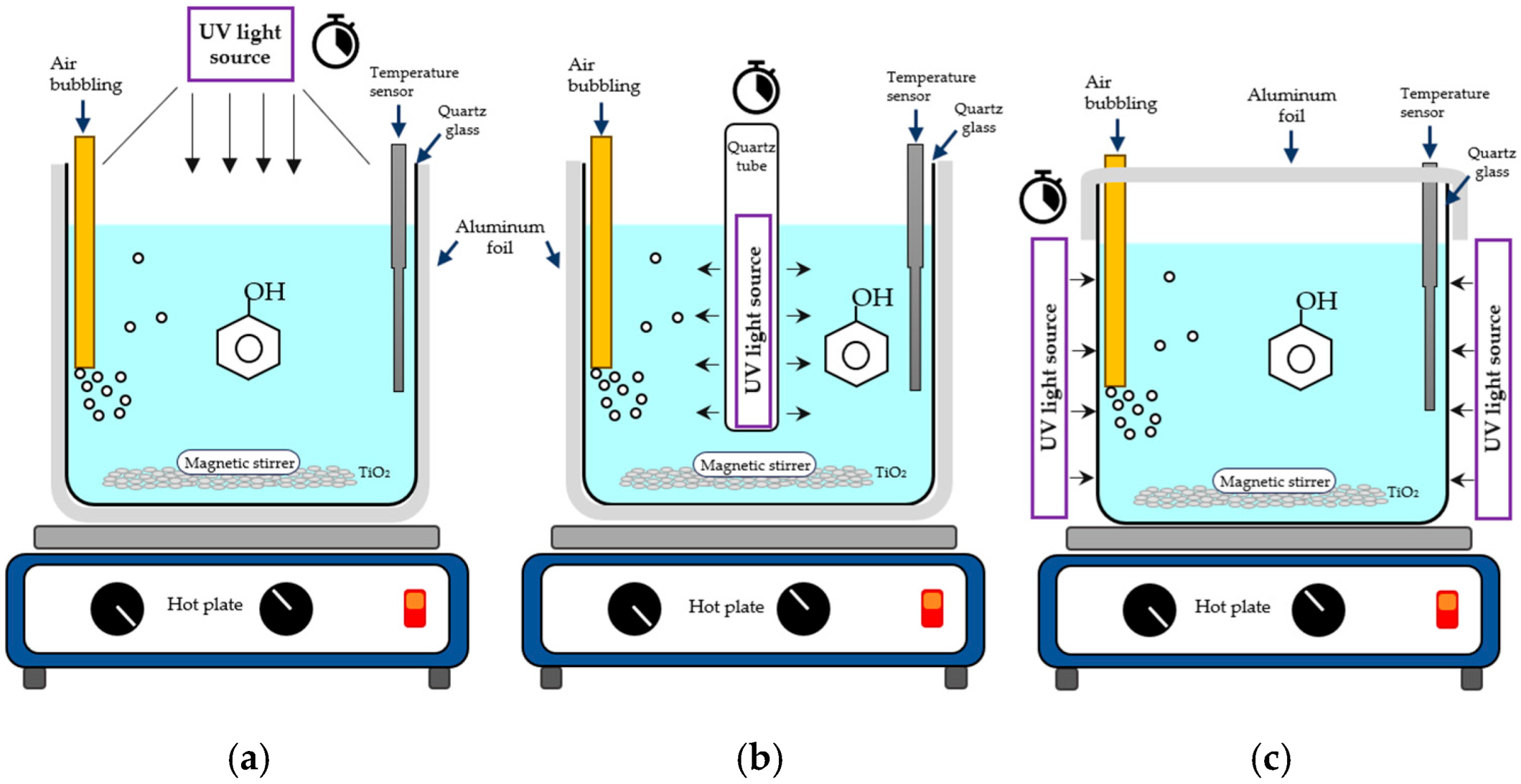
Figure 8. Representative image of the different photoreactor configurations to be used. (a) Direct radiation, (b) internal radiation, and (c) external radiation.
Catalysts 15 00748 g008
As previously described, each photoreactor included aluminum heatsinks to prevent LED overheating and avoid shifts in the emission wavelength peak. Additionally, the photoreactors were controlled using a Raspberry Pi 4 board (Raspberry Pi Foundation, Cambridge, UK) as a central processing unit. This board was primarily used to configure the optical power, irradiation time, and to monitor temperature. A K-thermocouple with a stainless-steel sheath, coupled with a digital converter MAX7725 (Maxim Integrated Products Inc., San José, CA, USA) was used for temperature measurement, providing a resolution of 0.25 °C. The photoreactors were fabricated from black polymethylmethacrylate (PMMA). Notably, each photoreactor allows for easy replacement of the radiation source; the default 365 nm LED can be interchanged with 385 nm or 405 nm LEDs, or any other wavelength provided the electrical characteristics remain the same. This feature enables broader applicability across various photocatalysts.
Irradiation patterns were measured in each photoreactor using a PM100D radiometer (Thorlabs Corp., Newton, NJ, USA) equipped with a S4125C thermal sensor (Thorlabs Corp., Newton, NJ, USA). For DRP configuration, measurements were taken in 0.4 mm increments along the XY plane. In the IRP and ERP configurations, measurements were recorded every 3°, covering a full 360° rotation. During all measurements, the LED driving current was set to 150 mA.

3.2. Photodegradation of Phenol

The photoreactors were evaluated in the photodegradation of phenol for two concentrations (50 ppm and 25 ppm). The experiments were conducted in a 150 mL quartz reactor. For the LED-based systems, the reactor was covered with aluminum foil in the cases of IRP and DRP, while only partially (upper part) in the ERP. As a reference system, a conventional UV lamp (UVP Products) was used, powered by a UV Pen-Ray source (254 nm, 2.8 W). All systems were adjusted to deliver a similar optical power of approximately 700 mW, as measured by a radiometer. A total of 100 mg of photocatalyst (TiO2 P25) was suspended in 100 mL of a phenol (ReagentPlus ≥ 99%, Evonik, Essen, Germany) solution, which was magnetically stirred in the dark under continuous aeration at 15 L/h, provided by an air pump operating with ambient air, until adsorption–desorption equilibrium was reached (30 min) [54]. Subsequently, the suspension was illuminated with the 365 nm light source of each photoreactor. For the UV lamp system, the lamp was placed inside a quartz tube and immersed directly into the suspension to ensure a total irradiation. Aliquots of 2.0 mL were taken, filtered (0.45 μm, Nylon syringe filters, Lab Instruments) and analyzed in a Shimadzu UV-6000 spectrophotometer (Kyoto, Japan). Changes in absorbance at 269 nm were registered, and corresponding concentrations were calculated through a calibration curve. The photodegradation efficiency was calculated using the following formula:
E f f i c i e n c y = C 0 C t C 0   ×   100   %
where C0 and Ct are the concentrations of phenol (ppm) at reaction times 0 and t in minutes, respectively [55].
The data of −ln (C/C0) vs. t for the phenol concentration were determined using the pseudo-first-order kinetics model as follows:
ln C C 0 = k t
where C and C0 are the concentration at time t (minutes) and the initial concentration, respectively; and k (min−1) is the apparent rate constant [56].

4. Conclusions

This study demonstrates that photoreactor configuration plays a critical role in the efficiency of phenol photodegradation. As demonstrated in the efficiency results and the reaction rate constant, for the photodegradation of phenol, the best photoreactor configuration was the IRP. LED-based systems showed high performance, positioning them as a sustainable alternative to traditional mercury or xenon lamps. The findings demonstrate that, with an appropriate reactor design, LEDs can serve as a sustainable and powerful alternative for the treatment of organic contaminants in water. In particular, the effective removal of phenol highlights the potential of these systems for addressing persistent and toxic pollutants commonly found in wastewater.

Author Contributions

Conceptualization, M.H.-C. and D.A.F.-B.; data Curation, B.I.-O., J.R.C.-B., D.A.F.-B. and K.R.-T.; formal analysis, B.I.-O., M.A.Á.-L., R.L.-G., M.H.-C., D.A.F.-B., K.R.-T. and J.D.R.-F.; investigation, B.I.-O., M.A.Á.-L., J.R.C.-B., M.H.-C., D.A.F.-B., K.R.-T. and J.D.R.-F.; methodology, D.A.F.-B., M.H.-C., M.A.Á.-L., R.L.-G., K.R.-T. and J.D.R.-F.; project administration, D.A.F.-B.; resources, M.H.-C. and D.A.F.-B.; supervision, M.H.-C. and D.A.F.-B.; validation, B.I.-O., M.A.Á.-L., R.L.-G., M.H.-C., D.A.F.-B., J.R.C.-B., K.R.-T. and J.D.R.-F.; visualization, B.I.-O., J.R.C.-B., M.H.-C., D.A.F.-B., K.R.-T. and J.D.R.-F.; writing—original draft, B.I.-O., M.A.Á.-L., R.L.-G., M.H.-C., D.A.F.-B., J.R.C.-B., K.R.-T. and J.D.R.-F.; writing—review and editing, M.A.Á.-L., R.L.-G., M.H.-C., D.A.F.-B., J.R.C.-B., K.R.-T. and J.D.R.-F.; funding acquisition, M.H.-C. and D.A.F.-B. All authors have read and agreed to the published version of the manuscript.

Funding

This work was supported by a grant from the Instituto Politécnico Nacional (IPN), SIP-20250286, awarded to Diego Adrián Fabila Bustos. Betsabé Ildefonso Ojeda has scholarships from SIP–IPN through the Programa de Maestría en Ingeniería y Diseño de Sistemas Sostenibles and Programa Institucional de Formación de Investigadores BEIFI-IPN.

Data Availability Statement

The data presented in this study are available on request from the corresponding author.

Acknowledgments

The comments and suggestions by the reviewers are deeply appreciated.

Conflicts of Interest

The authors declare no conflicts of interest.

Abbreviations

The following abbreviations are used in this manuscript:
AOPsAdvanced oxidation processes
ROSReactive oxygen species
LEDsLight emitting diodes
LEDLight emitting diode
UVUltraviolet
DRPDirect radiation photoreactor
IRPInternal radiation photoreactor
ERPExternal radiation photoreactor
TOCTotal Organic Carbon
DOCDissolved Organic Carbon
LC-MSLiquid Chromatography-Mass Spectrometry

References

  1. Colcha, P.D.G. Degradación del Fenol Presente en las Descargas de Aguas Residuales Industriales de la Refinería de Shushufindi Mediante foto Oxidación Catalítica Homogénea y Heterogénea para Descontaminación de sus Descargas. Bachelor’s Thesis, Escuela Superior Politécnica de Chimborazo, Riobamba, Ecuador, 2016. [Google Scholar]
  2. Mohd, A. Presence of phenol in wastewater effluent and its removal: An overview. Int. J. Environ. Anal. Chem. 2022, 102, 1362–1384. [Google Scholar] [CrossRef]
  3. Kulkarni, S.; Kaware, J. Review on research for removal of phenol from wastewater. Int. J. Sci. Res. Publ. 2018, 3, 2250–3153. [Google Scholar]
  4. Wang, Y.; Song, J.; Zhao, W.; He, X.; Chen, J.; Xiao, M. In situ degradation of phenol and promotion of plant growth in contaminated environments by a single Pseudomonas aeruginosa strain. J. Hazard. Mater. 2011, 192, 354–360. [Google Scholar] [CrossRef] [PubMed]
  5. Soto, H.M.; Palma, T.M.; García, M.; García-Mateos, R. Phenolic Compounds: Natural Sources, Importance and Applications; IntechOpen: London, UK, 2017. [Google Scholar] [CrossRef]
  6. Dang, T.T.T.; Le, S.T.T.; Channei, D.; Khanitchaidecha, W.; Nakaruk, A.D. Photodegradation mechanisms of phenol in the photocatalytic process. Res. Chem. Intermed. 2016, 42, 5961–5974. [Google Scholar] [CrossRef]
  7. Oller, I.; Gernjak, W.; Maldonado, M.I.; Pérez-Estrada, L.A.; Sánchez-Pérez, J.A.; Malato, S. Solar photocatalytic degradation of some hazardous water-soluble pesticides at pilot-plant scale. J. Hazard. Mater. 2006, 138, 507–517. [Google Scholar] [CrossRef] [PubMed]
  8. Ahmed, S.; Rasul, M.G.; Martens, W.N.; Brown, R.; Hashib, M.A. Heterogeneous photocatalytic degradation of phenols in wastewater: A review on current status and developments. Desalination 2010, 261, 3–18. [Google Scholar] [CrossRef]
  9. Granda, F.; Hicapié, M.G. Sistemas fotocatalíticos para el tratamiento de VOCs en corrientes gaseosas: Aspectos básicos y aplicaciones. Vector 2015, 10, 122. [Google Scholar]
  10. Jo, W.K.; Tayade, R.J. Recent developments in photocatalytic dye degradation upon irradiation with energy-efficient light emitting diodes. Chin. J. Catal. 2014, 35, 1781–1792. [Google Scholar] [CrossRef]
  11. Dutta, G.S.; Jatothu, B. Fundamentals and applications of light-emitting diodes (LEDs) in in vitro plant growth and morphogenesis. Plant Biotechnol. Rep. 2013, 7, 211–220. [Google Scholar] [CrossRef]
  12. Hölz, K.; Lietard, J.; Somoza, M.M. High-power 365 nm UV LED mercury arc lamp replacement for photochemistry and chemical photolithography. ACS Sustain. Chem. Eng. 2017, 5, 828–834. [Google Scholar] [CrossRef]
  13. Bertagna, S.D.; Buttiglieri, G.; Babić, T.; Ćurković, L.; Babić, S. Impact of UV-LED photoreactor design on the degradation of contaminants of emerging concern. Process Saf. Environ. Prot. 2021, 153, 94–106. [Google Scholar] [CrossRef]
  14. Khademalrasool, M.; Farbod, M.; Talebzadeh, M.D. The improvement of photocatalytic processes: Design of a photoreactor using high-power LEDs. J. Sci. Adv. Mater. Devices 2016, 1, 382–387. [Google Scholar] [CrossRef]
  15. Dai, K.; Lu, L.; Dawson, G. Development of UV-LED/TiO2 device and their application for photocatalytic degradation of methylene blue. J. Mater. Eng. Perform. 2012, 22, 1035–1040. [Google Scholar] [CrossRef]
  16. Ferreira, L.C.; Fernandes, J.R.; Peres, J.A.; Tavares, P.B.; Lucas, M.S. Wireless UV-A LEDs-driven AOP in the treatment of agro-industrial wastewaters. Environ. Res. 2021, 200, 111430. [Google Scholar] [CrossRef] [PubMed]
  17. Nyangaresi, P.O.; Qin, Y.; Chen, G.; Zhang, B.; Lu, Y.; Shen, L. Comparison of UV-LED photolytic and UV-LED/TiO2 photocatalytic disinfection for Escherichia coli in water. Catal. Today 2018, 335, 200–207. [Google Scholar] [CrossRef]
  18. Triquet, T.; Tendero, C.; Latapie, L.; Manero, M.; Richard, R.; Andriantsiferana, C. TiO2 MOCVD coating for photocatalytic degradation of ciprofloxacin using 365 nm UV LEDs—Kinetics and mechanisms. J. Environ. Chem. Eng. 2020, 8, 104544. [Google Scholar] [CrossRef]
  19. Schwarze, M.; Borchardt, S.; Frisch, M.L.; Collis, J.; Walter, C.; Menezes, P.W.; Strasser, P.; Driess, M.; Tasbihi, M. Degradation of phenol via an advanced oxidation process (AOP) with immobilized commercial titanium dioxide (TiO2) photocatalysts. Nanomaterials 2023, 13, 1249. [Google Scholar] [CrossRef]
  20. Mazierski, P.; Bajorowicz, B.; Grabowska, E.; Zaleska, M.A. Photoreactor design aspects and modeling of light. In Heterogeneous Photocatalysis; Green Chemistry and Sustainable Technology; Springer: Berlin/Heidelberg, Germany, 2016; pp. 211–248. [Google Scholar] [CrossRef]
  21. Lefèvre, S.; Boutin, O.; Ferrasse, J.H.; Malleret, L.; Faucherand, R.; Viand, A. Thermodynamic and kinetic study of phenol degradation by a non-catalytic wet air oxidation process. Chemosphere 2011, 84, 1208–1215. [Google Scholar] [CrossRef]
  22. Fujishima, A.; Zhang, X.; Tryk, D. TiO2 photocatalysis and related surface phenomena. Surf. Sci. Rep. 2008, 63, 515–582. [Google Scholar] [CrossRef]
  23. Khyave, A.E.; Mafigholmi, R.; Davood, A.; Mahvi, A.; Salimi, L. Photocatalytic degradation of azithromycin and ceftriaxone using synthesized Ag/g-C3N4/Fe3O4 nanocomposites in aqueous solution. Sci. Rep. 2025, 15, 18726. [Google Scholar] [CrossRef]
  24. Takhar, V.; Singh, S. Nanomaterials ROS: A Comprehensive Review for Environmental applications. Environ. Sci. Nano 2025, 12, 2516–2550. [Google Scholar] [CrossRef]
  25. Michalec, K.; Mozgawa, B.; Kusior, A.; Pietrzyk, P.; Sojka, Z.; Radecka, M. Tunable Generation of Reactive Oxygen Species in SnO2/SnS2 Nanostructures: Mechanistic Insights into Indigo Carmine Photodegradation. J. Phys. Chem. C 2024, 128, 5011–5029. [Google Scholar] [CrossRef]
  26. Schneider, J.T.; Firak, D.S.; Ribeiro, R.R.; Peralta-Zamora, P. Use of scavenger agents in heterogeneous photocatalysis: Truths, half-truths, and misinterpretations. Phys. Chem. Chem. Phys. 2020, 22, 15723–15733. [Google Scholar] [CrossRef]
  27. Bai, X.; Nie, M.; Diwu, Z.; Nie, H.; Wang, Y. Enhanced degradation and mineralization of phenol by combining two highly efficient strains with divergent ring-cleavage pathways. J. Water Process Eng. 2021, 39, 101743. [Google Scholar] [CrossRef]
  28. Hammouda, S.B.; Zhao, F.; Safaei, Z.; Srivastava, V.; Lakshmi, R.D.; Iftekhar, S.; Kalliola, S.; Sillanpää, M. Degradation and mineralization of phenol in aqueous medium by heterogeneous monopersulfate activation on nanostructured cobalt based-perovskite catalysts ACoO3 (A=La, Ba, Sr and Ce): Characterization, kinetics and mechanism study. Appl. Catal. B Environ. 2017, 215, 60–73. [Google Scholar] [CrossRef]
  29. Rangel, V.I.; Del Angel, G.; Ramos, R.E.; González, F.; Acevedo, P.P.; Gómez, C.M.; Tzompantzi, F.; Gutiérrez, O.N.; Torres, J.G. Improvement of photocatalytic activity in the degradation of 4-chlorophenol and phenol in aqueous medium using tin-modified TiO2 photocatalysts. RSC Adv. 2023, 13, 13862–13879. [Google Scholar] [CrossRef]
  30. Górska, P.; Zaleska, A.; Hupka, J. Photodegradation of phenol by UV/TiO2 and Vis/N,C-TiO2 processes: Comparative mechanistic and kinetic studies. Sep. Purif. Technol. 2009, 68, 90–96. [Google Scholar] [CrossRef]
  31. Zhang, T.; Sa, G.; Xu, A. Photocatalytic degradation of phenol with one-step hydrothermal synthesized Bi-TiO2. Vacuum 2024, 233, 113982. [Google Scholar] [CrossRef]
  32. Marcì, G.; Sclafani, A.; Augugliaro, V.; Palmisano, L.; Schiavello, M. Influence of some aromatic and aliphatic compounds on the rate of photodegradation of phenol in aqueous suspensions of TiO2. J. Photochem. Photobiol. A Chem. 1995, 89, 69–74. [Google Scholar] [CrossRef]
  33. Pera-Titus, M.; García-Molina, V.; Baños, M.A.; Giménez, J.; Esplugas, S. Degradation of chlorophenols by means of advanced oxidation processes: A general review. Appl. Catal. B Environ. Energy 2003, 47, 219–256. [Google Scholar] [CrossRef]
  34. Herrmann, J. Heterogeneous photocatalysis: Fundamentals and applications to the removal of various types of aqueous pollutants. Catal. Today 1999, 53, 115–129. [Google Scholar] [CrossRef]
  35. Turki, A.; Guillard, C.; Dappozze, F.; Ksibi, Z.; Berhault, G.; Kochkar, H. Phenol photocatalytic degradation over anisotropic TiO2 nanomaterials: Kinetic study, adsorption isotherms and formal mechanisms. Appl. Catal. B Environ. 2015, 163, 404–414. [Google Scholar] [CrossRef]
  36. Colmenares, J.C.; Xu, Y.-J. (Eds.) Heterogeneous Photocatalysis: From Fundamentals to Green Applications; Springer: Berlin/Heidelberg, Germany, 2015. [Google Scholar]
  37. Chong, M.N.; Jin, B.; Chow, C.W.K.; Saint, C. Recent developments in photocatalytic water treatment technology: A review. Water Res. 2010, 44, 2997–3027. [Google Scholar] [CrossRef]
  38. Udom, I.; Myers, P.D.; Ram, M.K.; Hepp, A.F.; Archibong, E.; Stefanakos, E.K.; Goswami, D.Y. Optimization of photocatalytic degradation of phenol using simple photocatalytic reactor. Am. J. Anal. Chem. 2014, 05, 743–750. [Google Scholar] [CrossRef]
  39. Liu, Z.; Qian, M.; Cheng, X.; Liu, Z. Recent advances in the photocatalytic degradation of phenol over Bi-based oxide catalysts. Processes 2024, 12, 1799. [Google Scholar] [CrossRef]
  40. Suhadolnik, L.; Pohar, A.; Likozar, B.; Čeh, M. Mechanism and kinetics of phenol photocatalytic, electrocatalytic and photoelectrocatalytic degradation in a TiO2-nanotube fixed-bed microreactor. Chem. Eng. J. 2016, 303, 292–301. [Google Scholar] [CrossRef]
  41. Mills, A.; Hunte, S.L. An overview of semiconductor photocatalysis. J. Photochem. Photobiol. A Chem. 1997, 108, 1–35. [Google Scholar] [CrossRef]
  42. Jamil, Q.; Rana, K.B.; Matoh, L.A. CFD Study on Optimization of Mass Transfer and Light Distribution in a Photocatalytic Reactor with Immobilized Photocatalyst on Spheres. Water 2024, 16, 1828. [Google Scholar] [CrossRef]
  43. Turchi, C. Photocatalytic degradation of organic water contaminants: Mechanisms involving hydroxyl radical attack. J. Catal. 1990, 122, 178–192. [Google Scholar] [CrossRef]
  44. Khan, Z.; Kamal, M.; Jaafar, J.; Mir, F.; Rehman, G.U.; Khan, A.A.; Ismail, A.; Matsuura, T.; Othman, M.; Rahman, M.A. Recent advances in photoreactor designs for the degradation of persistent organic contaminants with influential effects of configuration and parameters: A review. J. Water Process Eng. 2024, 69, 106825. [Google Scholar] [CrossRef]
  45. Tran, H.D.; Nguyen, D.Q.; Do, P.T.; Tran, U.N.P. Kinetics of photocatalytic degradation of organic compounds: A mini-review and new approach. RSC Adv. 2023, 13, 16915–16925. [Google Scholar] [CrossRef]
  46. Martin, M.V.; Ipiña, A.; Villabrille, P.I.; Rosso, J.A. Combination of sunlight, oxidants, and Ce-doped TiO2 for phenol degradation. Environ. Sci. Pollut. Res. Int. 2017, 24, 6013–6021. [Google Scholar] [CrossRef]
  47. Subagio, D.P.; Srinivasan, M.; Lim, M.; Lim, T.T. Photocatalytic degradation of bisphenol-A by nitrogen-doped TiO2 hollow sphere in a vis-LED photoreactor. Appl. Catal. B Environ. 2010, 95, 414–422. [Google Scholar] [CrossRef]
  48. Belekbir, S.; El Azzouzi, M.; El Hamidi, A.; Rodríguez, L.L.; Santaballa, J.A.; Canle, M. Improved photocatalyzed degradation of phenol as a model pollutant over metal-impregnated nanosized TiO2. Nanomaterials 2020, 10, 996. [Google Scholar] [CrossRef] [PubMed]
  49. Jamali, A.; Vanraes, R.; Hanselaer, P.; Gerven, T.V. A batch LED reactor for the photocatalytic degradation of phenol. Chem. Eng. Process.—Process. Intensif. 2013, 71, 43–50. [Google Scholar] [CrossRef]
  50. Chatterjee, D.; Dasgupta, S. Visible light induced photocatalytic degradation of organic pollutants. J. Photochem. Photobiol. C Photochem. Rev. 2005, 6, 186–205. [Google Scholar] [CrossRef]
  51. Miller, J.S. Rose bengal-sensitized photooxidation of 2-chlorophenol in water using solar simulated light. Water Res. 2004, 39, 412–422. [Google Scholar] [CrossRef]
  52. Daneshvar, N.; Salari, D.; Khataee, A. Photocatalytic degradation of azo dye acid red 14 in water on ZnO as an alternative catalyst to TiO2. J. Photochem. Photobiol. A Chem. 2003, 162, 317–322. [Google Scholar] [CrossRef]
  53. Hübner, U.; Spahr, S.; Lutze, H.; Wieland, A.; Rüting, S.; Gernjak, W.; Wenk, J. Advanced oxidation processes for water and wastewater treatment—Guidance for systematic future research. Heliyon 2024, 10, e30402. [Google Scholar] [CrossRef] [PubMed]
  54. Bekkouche, S.; Bouhelassa, M.; Salah, N.H.; Meghlaoui, F. Study of adsorption of phenol on titanium oxide (TiO2). Desalination 2004, 166, 355–362. [Google Scholar] [CrossRef]
  55. Bharali, D.; Saikia, S.; Devi, R.; Choudary, B.M.; Gour, N.K.; Deka, R.C. Photocatalytic degradation of phenol and its derivatives over ZnFe layered double hydroxide. J. Photochem. Photobiol. A Chem. 2023, 438, 114509. [Google Scholar] [CrossRef]
  56. Kumar, R.; Kumar, S.A.; Sarathi, M.P. Study of UV assisted photocatalytic degradation of organic dye. Mater. Today Proc. 2022, 66, 3244–3249. [Google Scholar] [CrossRef]
Figure 1. Photographs of the photoreactors in operation. (a) DRP, (b) IRP, and (c) ERP.
Catalysts 15 00748 g001
Figure 2. Beaker irradiation with (a) a UV lamp and at 365 nm with (b) DRP, (c) IRP, and (d) ERP.
Catalysts 15 00748 g002
Figure 3. Absorption spectrum of 25 ppm phenol photodegradation with (a) DRP, (b) IRP, (c) ERP, and (d) UV lamp.
Catalysts 15 00748 g003
Figure 4. Absorption spectrum of 50 ppm phenol photodegradation with (a) DRP, (b) IRP, (c) ERP, and (d) UV lamp.
Catalysts 15 00748 g004
Figure 5. Efficiency of photolysis for (a) 25 ppm and (b) 50 ppm.
Catalysts 15 00748 g005
Figure 6. Evaluation of phenol degradation (25 ppm) (a) photodegradation efficiency and (b) reaction kinetics.
Catalysts 15 00748 g006
Figure 7. Evaluation of phenol degradation (50 ppm) (a) photodegradation efficiency and (b) reaction kinetics.
Catalysts 15 00748 g007
Table 1. Pseudo-first-order rate constants (k) for photodegradation of phenol at two concentrations in different photoreactor configurations.
System25 ppm50 ppm
k (min−1)R2k (min−1)R2
DRP0.01970.990.00450.98
ERP0.01640.970.00490.98
IRP0.03350.960.01560.98
UV lamp0.04500.970.01770.98
Table 2. Half-life times (t1/2) calculated from the pseudo-first-order kinetic constant for different initial phenol concentrations and irradiation systems.
Systemt1/2 (min)
25 ppm50 ppm
DRP35.18154
ERP42.26141.43
IRP20.6944.42
UV lamp15.439.15
Table 3. Photodegradation phenol efficiency and kinetics reported in the literature.
ReferenceStudy ConditionsPhotodegradation Efficiency/Rate ConstantTime
Turki et al. [35]30 mL of phenol (10 mg/L), 30 mg TiO2, mercury lamp (365 nm, 125 W)95%
k = 6.56 × 10⁻³ min−1
60 min
Jamali et al. [49]10 mg/L de phenol, 20 mm × 50 mm cell, LED (375 nm)42%
k = 2.37 × 10⁻⁵ min−1
480 min
Belekbir et al. [48]200 mL of phenol (50 ppm), mercury lamp (366 nm), immersion photoreactor with quartz tube with water circulation70%
k = 76.5 × 10⁻³ min−1
60 min
This study
(FRD; FRE; FRI; UV lamp)
100 mL of phenol (25 ppm), 100 mg TiO2 P25, LEDs (365 nm) and UV lamp (254 nm), quartz glass 150 mL90.17%, 85.24%, 97.79%, 99.6%.
k = 19.7 × 10⁻³ min−1, 16.4 × 10⁻³ min−1, 33.5 × 10⁻³ min−1, 45.0 × 10⁻³ min−1.
120 min
100 mL of phenol (50 ppm), 100 mg TiO2 P25, LEDs (365 nm) and UV lamp (254 nm), quartz glass 150 mL41.21%, 45.83%, 84.81%, 89.80%.
k = 4.5 × 10⁻³ min−1, 4.9 × 10⁻³ min−1, 15.9 × 10⁻³ min−1, 17.7 × 10⁻³ min−1
120 min
Disclaimer/Publisher’s Note: The statements, opinions and data contained in all publications are solely those of the individual author(s) and contributor(s) and not of MDPI and/or the editor(s). MDPI and/or the editor(s) disclaim responsibility for any injury to people or property resulting from any ideas, methods, instructions or products referred to in the content.