Article

Interfacial Electric Fields and Chemical Bonds in Ti3C2O-Crafted AgI/MoS2 Direct Z-Scheme Heterojunction Synergistically Expedite Photocatalytic Performance

1
School of Science, China University of Geosciences (Beijing), Beijing 100083, China
2
School of Earth Sciences and Resources, China University of Geosciences (Beijing), Beijing 100083, China
*
Author to whom correspondence should be addressed.
These authors contributed equally to this work.
Catalysts 2025, 15(8), 740; https://doi.org/10.3390/catal15080740 (registering DOI)
Submission received: 22 June 2025 / Revised: 27 July 2025 / Accepted: 30 July 2025 / Published: 3 August 2025

Abstract

The photocatalytic performance of heterojunctions is often restricted by inferior contact interface and low charge transfer efficiency. In this work, Ti3C2O MXene was crafted with AgI/MoS2 to produce a Z-scheme heterojunction (AgI/MoS2/Ti3C2O). Interfacial electric fields and chemical bonds were proven to exist in the heterojunction. The interfacial electric fields supplied a powerful driving force, and the interfacial Ti-O-Mo bonds served as an atomic-level channel for synergistically expediting the vectorial transfer of photogenerated carriers. As a result, AgI/MoS2/Ti3C2O exhibited significantly improved photocatalytic activity, demonstrating a high H2O2 production rate of 700 μmol·g−1·h−1 and a rapid degradation of organic pollutants.

Graphical Abstract

1. Introduction

The energy crisis and environmental pollution have emerged as two major challenges for humanity, intensifying alongside rapid urbanization and industrialization [1,2,3]. Various cutting-edge technologies have been sought to dissolve the two issues. Among numerous methods, solar energy utilization has emerged as the most effective candidate for addressing energy shortages and environmental contaminants [4,5,6]. On one hand, artificial photosynthesis mimics natural photosynthesis processes and produces a variety of valuable chemicals [7,8,9]. On the other hand, photocatalytic degradation employs renewable solar energy to create active free radicals that oxidize and break down organic pollutants [10,11,12]. Hydrogen peroxide (H2O2) plays a vital role in both photosynthesis and photocatalytic degradation. As a significant product of photosynthesis, H2O2 is regarded as a green and clean energy source with high energy density that is suitable for using in one-compartment fuel cells [13,14]. Additionally, H2O2 is recognized as a clean and versatile oxidant utilized in advanced oxidation processes. It can be converted into hydroxyl radicals (•OH), which efficiently degrade or even completely mineralize organic pollutants [15,16]. Beyond these applications, H2O2 serves as a potent disinfectant in water treatment [17] and an efficient oxidant in fuel desulfurization processes [18], demonstrating its versatility in environmental remediation. Therefore, the development of a photocatalyst for efficient H2O2 production is a “kill two birds with one stone” strategy for addressing energy needs and environmental remediation.
Various approaches have been investigated to develop photocatalysts with high efficiency in producing H2O2 [19,20]. Among the strategies to enhance interfacial charge transfer and spatial carrier separation, constructing a catalyst with a heterojunction structure is a trendy tactic [21,22]. A charge transport channel must be established within the heterojunctions to facilitate the directional transfer of photogenerated carriers at the interfaces. The interfacial chemical bonds can act as efficient atomic-level charge transport channels, significantly accelerating the migration of photoinduced electrons and holes along opposite orientations, leading to a dramatic enhancement in photocatalytic activity. For instance, Zhang et al. [23] combined Bi2Sn2O7 with BiOBr to create an S-scheme heterojunction featuring interfacial Bi-O bonds. This design significantly enhanced the photocatalytic nitrogen reduction, yielding 459.04 μmol·g−1·h−1 of ammonia in pure water. Zhao et al. [24] developed an In-O-Cd bond-modulated S-scheme heterojunction to boost photoinduced electron transfer and reduce the electron transfer distance, thereby enhancing the photocatalytic CO2 reduction process.
Furthermore, the interfacial electric field has been identified as another driving force in heterojunctions for efficiently separating photogenerated electrons and holes, as well as speeding up their directional transfer [25,26,27]. Zhu et al. [28] integrated Mo-modified ZnIn2S4 nanosheets with NiTiO3 microrods to synthesize an S-scheme heterojunction with an enhanced interfacial electric field. The heterojunction exhibited a high H2 evolution rate of 14.06 mmol·g−1·h−1 and an apparent quantum efficiency of 44.10% at 420 nm, attributed to the interfacial electric field’s capability to efficiently separate and regulate photogenerated carriers. Jiang et al. [29] described an S-scheme heterojunction composed of NH2-MIL-125-Ti/WO3-x with a robust interfacial electric field. This heterojunction efficiently enabled the simultaneous production of CO (12.57 μmol·g−1·h−1) and H2O2 (8.41 μmol·g−1·h−1) without requiring a sacrificial agent due to the carrier separation effect enhanced by the interfacial electric field.
The significance of interfacial chemical bonds and electric fields in enhancing the photocatalytic process has been clearly demonstrated above. However, there are virtually no examples of both effects being utilized simultaneously in photocatalytic H2O2 production. Therefore, the concept of creating a heterojunction with an interfacial electric field and chemical bonds to synergistically enhance its photocatalytic performance is promising and warrants further exploration. In this work, a Ti3C2O MXene-crafted AgI/MoS2 (AgI/MoS2/Ti3C2O) direct Z-scheme heterojunction was prepared and utilized as a photocatalyst for both H2O2 production and the degradation of organic contaminants. In addition to the traditional semiconductors AgI and MoS2, we also incorporated Ti3C2O MXene, which is a novel two-dimensional metallic nanomaterial with a large specific surface area and a high abundance of surface-exposed metal atoms. These advantages confer it with excellent light absorption and efficient carrier transport properties. The resulting AgI/MoS2/Ti3C2O Z-scheme heterojunction was demonstrated to possess a strong interfacial electric field and a Ti-O-Mo chemical bond, facilitating high rates of H2O2 production and a rapid degradation of organic pollutants.

2. Results and Discussion

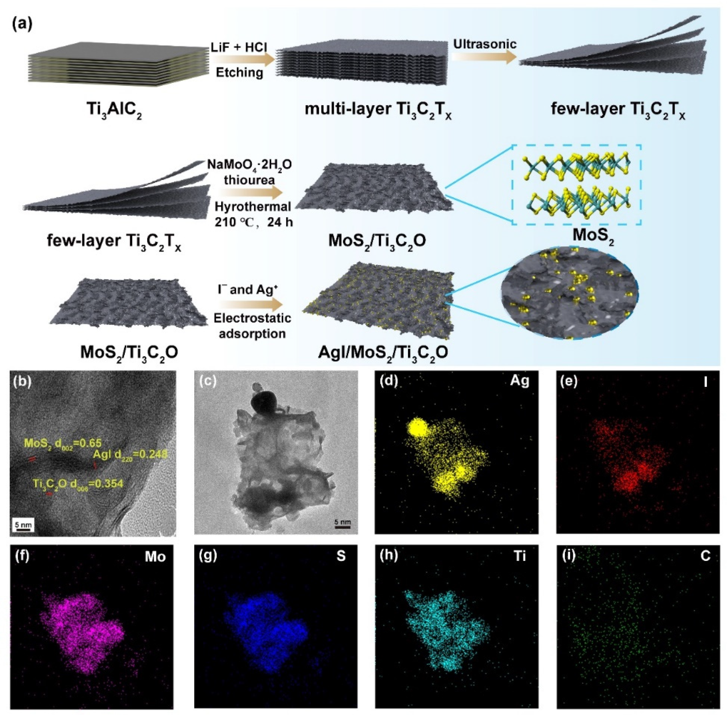
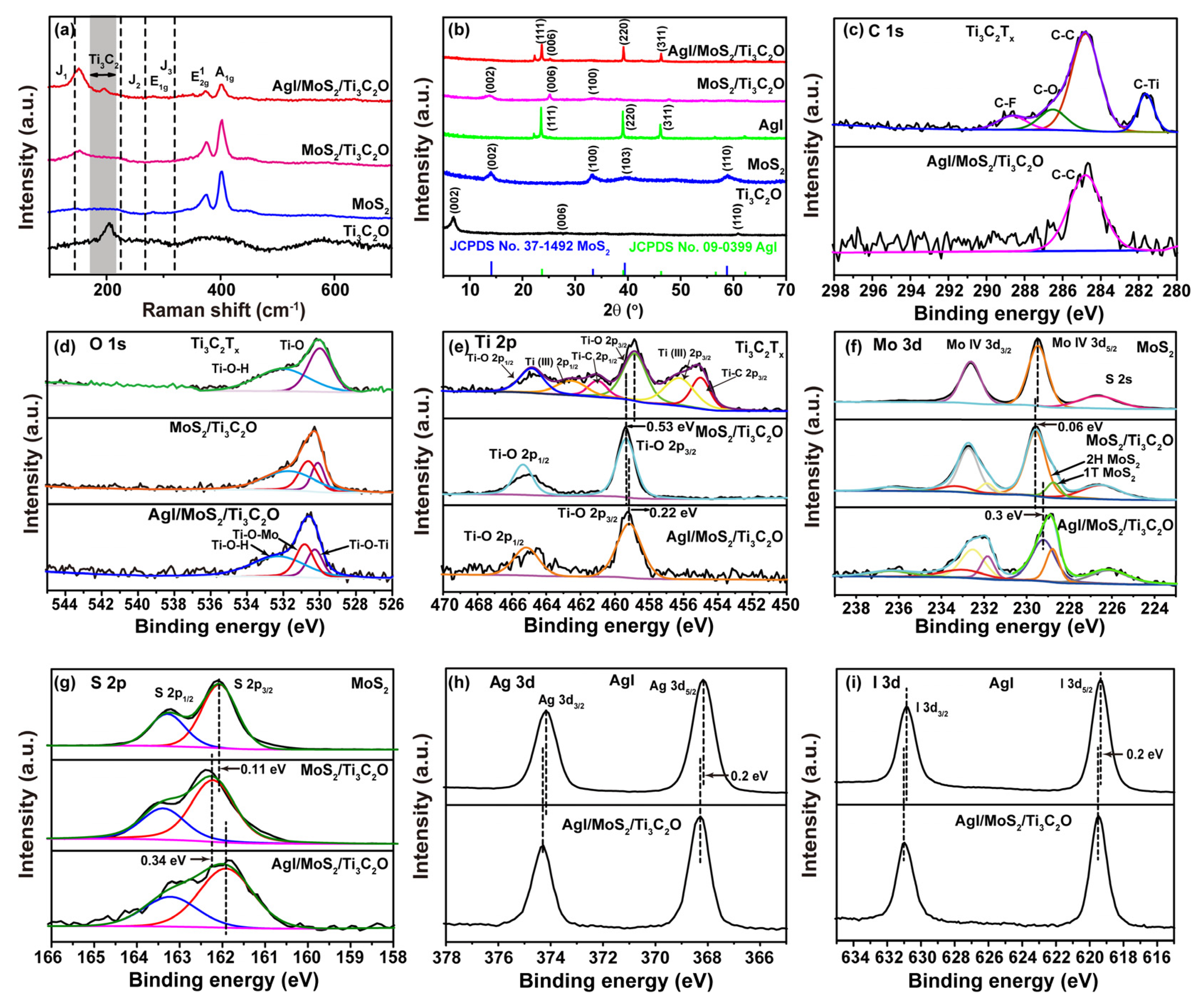
2.1. Characterization of AgI/MoS2/Ti3C2O Z-Scheme Heterojunction

As described in Figure 1a, the AgI/MoS2/Ti3C2O Z-scheme heterojunction was prepared by a three-step procedure. First, Ti3AlC2 was etched to produce multi-layer Ti3C2Tx, which presented the characteristic accordion-like MXene morphology (Figure S1a) but with limited interlaminar space for semiconductor growth [30,31]. Multi-layer Ti3C2Tx was exfoliated to be few-layer to provide a larger surface area for semiconductor growth (Figure S1b). Then, MoS2 grew on the surface of Ti3C2Tx through a hydrothermal process to produce MoS2/Ti3C2O compound. Pure MoS2 presented a spheric flower-like shape (Figure S1c). After composition, MoS2 grew evenly on the Ti3C2O surface, forming a planar structure due to the growth foundation provided by Ti3C2O and preventing MoS2 agglomeration (Figure S1d). Finally, the AgI/MoS2/Ti3C2O heterojunction was obtained through self-assembly. In Figure 1b, AgI/MoS2/Ti3C2O heterojunction displays a lamellar shape. The lattice fringes with interlayer spacing of 0.65 nm were attributed to the few layers of MoS2 in the (002) crystal plane with vertically aligned edges, which was significantly larger than the interlayer distance of bulk crystals (about 0.62 nm) [32]. A similar lattice expansion had been reported for the formed metallic 1T′-MoS2 [33]. These vertically aligned MoS2 crystals on the Ti3C2O surface were beneficial for mass diffusion and charge transfer processes during photocatalytic reactions, given the significant three orders of magnitude higher electron mobility within the MoS2 plane compared to the plane perpendicular to the base plane [34,35,36]. In addition, distinct lattice fringes were observed in the HRTEM images. The spacing of d = 0.354 nm was assigned to the (006) plane of Ti3C2O, and spherical lattice fringes of d = 0.248 nm belonged to the (220) plane of AgI, confirming the successful synthesis of the AgI/MoS2/Ti3C2O heterojunction. Furthermore, EDS mapping in Figure 1c–i shows the well-dispersed presence of Ag, I, Ti, C, Mo, and S elements, further confirming the successful construction of the AgI/MoS2/Ti3C2O heterojunction.
Raman spectra provided relevant microstructure information (Figure 2a). The characteristic peaks at around 379 and 402 cm−1 corresponded to the in-plane ( E 2 g 1 ) and out-of-plane ( A 1 g ) Mo-S phonon modes of 2H-MoS2, respectively [35]. The relatively high intensity of the A 1 g mode in the AgI/MoS2/Ti3C2O heterojunction indicated that the vertically aligned MoS2 in the heterojunction had an edge termination structure [36]. Moreover, the characteristic peaks of J1, J2, and J3 were not obvious in MoS2 owing to the low content of 1T′ phase MoS2, which gradually increased following the formation of the heterojunction [37]. In addition, compared to pure Ti3C2O, the peak of MoS2/Ti3C2O and AgI/MoS2/Ti3C2O at 203 cm−1 decreased because the Ti3C2O surface in MoS2/Ti3C2O and AgI/MoS2/Ti3C2O was covered by 2H-MoS2 [38]. The X-ray powder diffraction (XRD) pattern of the heterojunction showed the characteristic peaks of AgI, MoS2, and Ti3C2O, confirming their successful combination (Figure 2b). The X-ray photoelectron spectra (XPS) procedure was performed to analyze the surface chemical composition of the heterojunction. Carbon C 1s with a binding energy of 284.8 eV was used as the standard reference. Ag, I, Mo, S, Ti, C, and O were found in the survey spectrum of the heterojunction (Figure S2). The C-Ti bond disappeared in the C 1s XPS profile of the heterojunction, indicating that the C-Ti bond broke during synthesis (Figure 2c). Ag+ ions easily adsorbed onto the surface of Ti3C2O, which had abundant surface-active O-containing groups and grew to be AgI, resulting in the rupture of the C-Ti bond [39]. In the XPS spectra of O 1s (Figure 2d), the peaks at 530.3 and 530.8 eV were ascribed to Ti-O-Ti and Ti-O-Mo bonds, respectively, demonstrating the interaction between Ti3C2O and MoS2 and the successful formation of interfacial chemical bonds [40]. The peak at 532.8 eV belonged to the Ti-O-H bond [41]. The Ti 2p core level of Ti3C2Tx was fitted with three doublets (Ti 2p3/2-Ti 2p1/2) (Figure 2e) [42]. The signals at 458.85 and 464.85 eV belonged to Ti(IV) 2p3/2 and Ti(IV) 2p1/2 of the oxygen-containing group’s Ti-O bond on the Ti3C2Tx surface [43], respectively, while the signals at 455.01, 456.25, 461.01, and 462.53 eV were ascribed to Ti(II) 2p3/2, Ti (III) 2p3/2, Ti(II) 2p1/2 and Ti (III) 2p1/2, respectively. The Ti-O doublet peaks of the heterojunction were intense due to the large number of oxygen-containing functional groups generated during the hydrothermal process of Ti3C2O synthesis [44,45]. In the high-resolution XPS spectra of Mo, the two characteristic peaks at 229.46 and 232.61 eV were ascribed to Mo 3d5/2 and Mo 3d3/2, respectively (Figure 2f). It is worth noting that the characteristic peak of 1T′ phase MoS2 appeared in MoS2/Ti3C2O and was enhanced in AgI/MoS2/Ti3C2O, which was consistent with Raman results. In addition, the peak at 226.54 eV belonged to S 2s [43,45]. In the XPS spectrum of S 2p (Figure 2g), 162.04 and 163.25 eV corresponded to S 2p3/2 and 2p1/2, respectively. The peaks attributed to Ag 3d5/2 and Ag 3d3/2 were located at 368.10 and 374.10 eV (Figure 2h), respectively, while the peaks attributed to I 3d5/2 and I 3d3/2 were located at 619.30 and 630.80 eV (Figure 2i), respectively. Peak shifts were observed in the XPS spectra of Ti 2p, Mo 3d, S 2p, Ag 3d, and I 3d. The Ti(IV) 2p3/2 of MoS2/Ti3C2O positively shifted 0.53 eV due to the oxygen-containing functional groups generated during the synthetic process. Compared with pure MoS2, the Mo 3d and S 2p of MoS2/Ti3C2O positively shifted 0.06 eV and 0.11 eV, respectively, indicating that electrons transferred from MoS2 to Ti3C2O. After the formation of AgI/MoS2/Ti3C2O, Ti(IV) 2p3/2, Mo 3d, and S 2p negatively shifted 0.22 eV, 0.3 eV, and 0.34 eV, respectively, indicating that electrons transferred from AgI to MoS2/Ti3C2O, explaing why Ag 3d and I 3d positively shifted 0.20 eV compared to pure AgI. The above results demonstrate the interfacial chemical bond and charge redistribution between components of the heterojunction which were favorable for interfacial electric field formation.

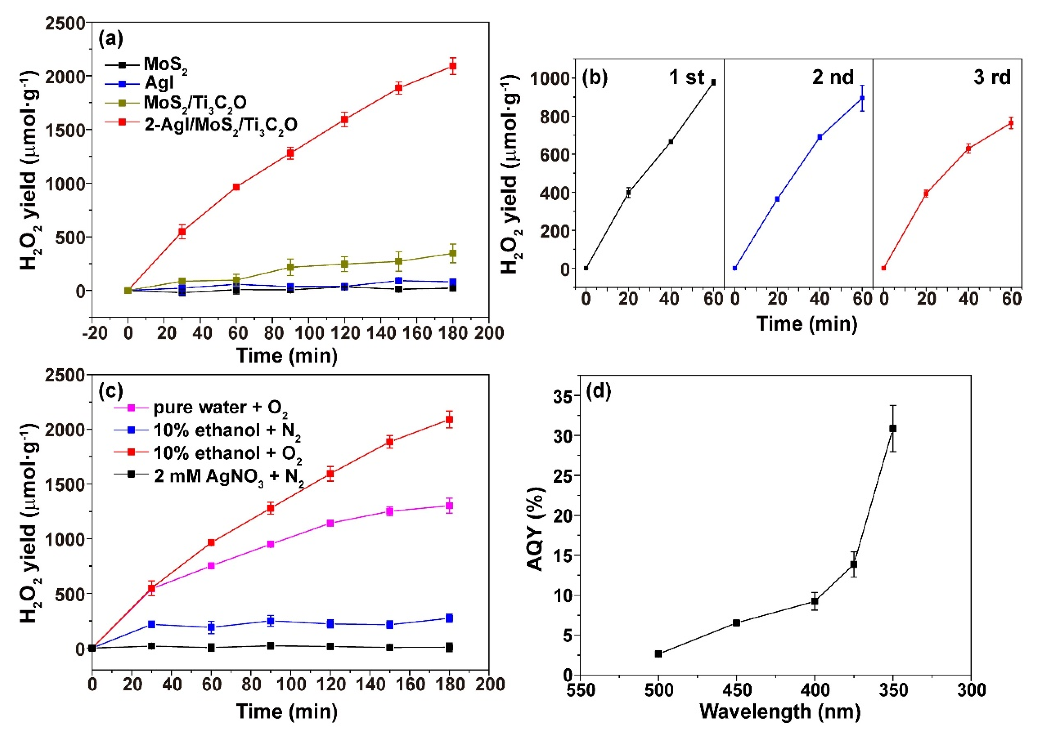
2.2. Photocatalytic H2O2 Production

Since H2O2 is a significant chemical and the main source of reactive oxygen species (ROS) for photodegradation, the photocatalytic performance of the AgI/MoS2/Ti3C2O heterojunction for H2O2 production was evaluated under simulated sunlight using ethanol as a sacrificial reagent. Figure 3a illustrates that the heterojunction exhibited a H2O2 yield of 700 μmol g−1 h−1, while the H2O2 production rates of pure semiconductors were negligible. The photocatalytic H2O2 production of MoS2/Ti3C2O also was not substantial, demonstrating the vital role of AgI in the heterojunction. Various mass ratios of AgI within the heterojunction resulted in different photocatalytic H2O2 production rates (Figure S3a). 2-AgI/MoS2/Ti3C2O displayed the highest photocatalytic H2O2 yield. Compared to other photocatalysts (Table S1), the AgI/MoS2/Ti3C2O heterojunction demonstrated notable advantages in H2O2 yield efficiency. The formation and decomposition rates of H2O2 were quantitatively analyzed (Equation (S1)) since the two processes occurred simultaneously during the photocatalytic H2O2 production. Among the heterojunction with different mass ratios of AgI, 2-AgI/MoS2/Ti3C2O exhibited the largest difference between the formation constant (Kf) and decomposition constant (Kd), confirming that it had the best H2O2 yield (Figure S3b). Furthermore, the stability of the heterojunction was evaluated. After three reaction cycles, the H2O2 yield remained at 90% of the first run (Figure 3b). Furthermore, the XRD analysis of AgI/MoS2/Ti3C2O showed that its structure remained stable after three cycles of reaction (Figure S4), and AgI did not undergo photoreduction. In addition, the yield of H2O2 in pure water reached about 430 μmol g−1 h−1 (Figure 3c). To investigate the role that O2 played in the photocatalytic production of H2O2, dissolved O2 was removed by bubbling with N2, which then resulted in an 87% decrease in H2O2 production. Subsequently, upon introducing the electron trapping agent AgNO3, no H2O2 was detected in the N2 atmosphere. The dependence of H2O2 yield on wavelength was measured under various light sources equipped with different filters. Figure 3d outlines that the AQYs of the heterojunction at 350 nm, 375 nm, 400 nm, 450 nm, and 500 nm were 30.85%, 13.80%, 9.23%, 6.53%, and 2.63%, respectively.

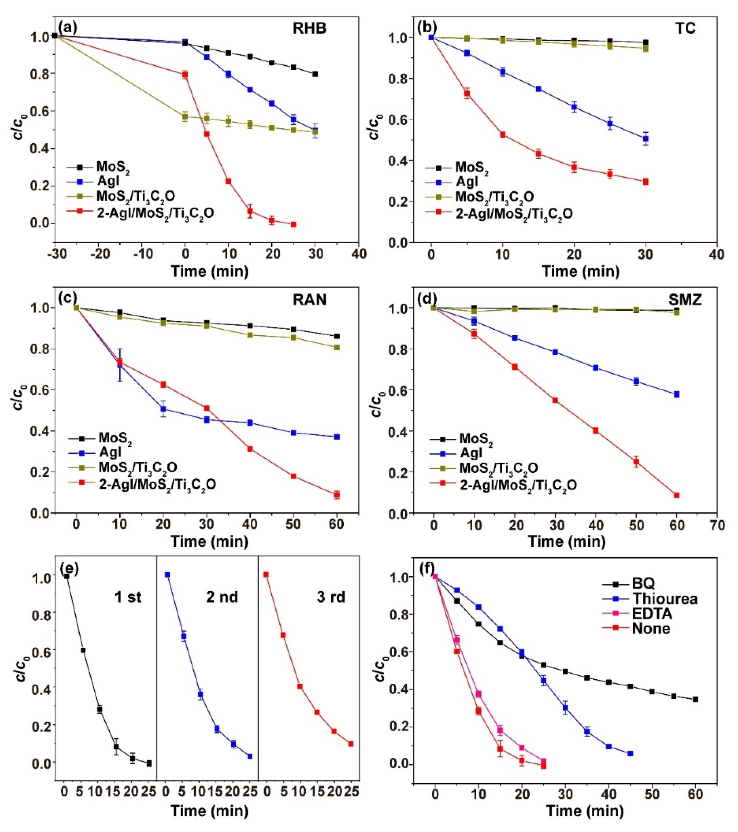
2.3. Photodegradation Activity

One common dye, Rhodamine B (RHB), and three kinds of antibiotics—tetracycline hydrochloride (TC), ranitidine (RAN), and sulfamethazine (SMZ)—were selected as typical organic pollutants to evaluate the photodegradation performance of the as-prepared heterojunction. These pollutants are usually difficult to degrade and pose a great threat to human health and the environment. As shown in Figure 4a–d, the prepared heterojunction 2-AgI/MoS2/Ti3C2O exhibited the highest photodegradation efficiency for the four kinds of pollutants compared with AgI, MoS2, and MoS2/Ti3C2O. Only 20% and 50% of RHB were degraded within half an hour by the pure semiconductors AgI and MoS2, respectively (Figure 4a). MoS2/Ti3C2O displayed 50% degradation efficiency for RHB after half an hour of dark reaction due to the excellent absorbability of Ti3C2O. Among the heterojunction with different mass ratios of AgI, 2-AgI/MoS2/Ti3C2O displayed the highest photodegradation efficiency (Figure S6). Similar to the photocatalytic production of H2O2, the degradation efficiency of 2-AgI/MoS2/Ti3C2O was found to decrease slightly after three repeated degradation tests (Figure 4e). Compared to the adsorption-based removal of RHB using Tabebuia rosea peel (yielding 90% efficiency in 5 h) [46], our AgI/MoS2/Ti3C2O Z-scheme heterojunction achieved better degradation within a shorter time, demonstrating superior photocatalytic performance. In order to further understand the role of ROS played during the degradation process, RHB degradation was taken as an example to conduct radical quenching tests. EDTA-2Na, p-benzoquinone (BQ), and thiourea were used as scavengers of hole, superoxide anions (O2), and hydroxyl radicals (OH), respectively. As shown in Figure 4f, degradation efficiency was greatly reduced in the presence of BQ and thiourea, demonstrating that O2 and OH played vital roles in the degradation process. EDTA-2Na slightly decreased the degradation efficiency, indicating that hole did not directly act on the pollutants.

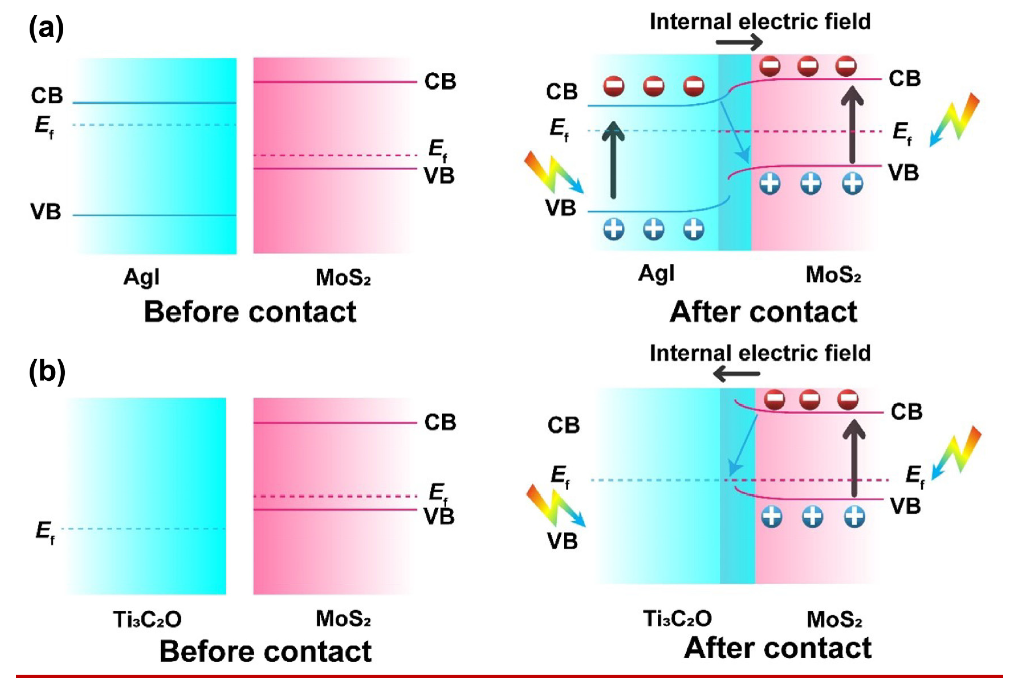
2.4. Photocatalytic Mechanism

2.4.1. Band Structure

The light absorption and band structure of the prepared samples were surveyed by UV/Vis diffuse reflection spectroscopy (DRS), ultraviolet photoelectron spectroscopy (UPS), and in-situ XPS spectra. As demonstrated in Figure 5a, AgI displayed weak absorption in the interval of the visible light window. Obviously, the light absorption intensity and boundary of AgI/MoS2/Ti3C2O were effectively enhanced and extended compared to AgI. The reason was primarily attributed to the strong light-harvesting abilities of Ti3C2O and MoS2. The Kubelka–Munk transform (Equation (1)) is a standard method for estimating the optical bandgap from DRS data [47,48]. This approach is widely adopted for semiconductors like AgI [49] and MoS2 [50], as evidenced by recent studies. According to the Kubelka–Munk equation, the band gaps (Eg) of AgI and MoS2 were established to be 1.8 eV and 2.7 eV, respectively (Figure 5b).
( α h ν ) n = B ( h ν E g )
Here, B is constant, h is Planck constant (4.13  × 10−15 eV⋅s), ν (Hz) is light frequency, Eg (eV,) and α (cm−1) is the band gap energy and light absorption coefficient, respectively. AgI and MoS2 are direct semiconductors (n  =  2).
The UPS technique was employed to acquire energy level information on the semiconductor interface. As shown in Figure 5c, the work functions (Φ) of AgI and MoS2 were detected to be 4.24 eV and 5.24 eV, respectively. The Φ value of AgI was proven to be smaller than that of MoS2. Thus, the interfacial electric field easily formed when AgI and MoS2 contacted. Free electrons in AgI with a low work function spontaneously diffused to MoS2 with a high work function to equilibrate the fermi energy level (Ef) of the two components. For AgI and MoS2, the energy gap between the valence band (VB) and Fermi level were calculated to be 2.64 eV and 0.22 eV, respectively. Mott–Schottky curves (Figure S6) revealed that both AgI and MoS2 exhibited a positive slope, displaying n-type semiconductor traits. The flat band potential (Efb) of MoS2 and AgI were determined to be −1.00 V and −0.60 V (vs Ag/AgCl), respectively. The conduction band (CB) potential of AgI and MoS2 were calculated to be −0.40 V and −0.80 V (vs normal hydrogen electrode), respectively, using the formulas (Equations (S2) and (S3)), and they were approximately equal to Efb. Moreover, in-situ XPS was coupled with a xenon lamp to record the binding energy shift direction, which was aimed at predicting the photoinduced charge separation and transfer direction in the heterojunction. It can be seen in Figure 5d–f that, under illumination, both Ag 3d and Mo 3d peaks shifted to the positive direction, while low-valence Ti (II) 2p peaks appeared at more negative positions. Ti3C2 with O terminal had large work function and easily accepted photoinduced electrons as electron traps [45]. As an electron-trapping trap, Ti3C2O promoted rapid electron migration between AgI and MoS2, and at the same time, the electrons of AgI continuously transferred to MoS2. The above results unveil that the interfacial electric field constructed in the Z-type heterojunction acted as a powerful driving force to facilitate charge separation and guided charge migration, and the Ti-O-Mo interface chemical bond served as an atomic-level charge transfer channel, accelerating the rapid charge migration. Their band structure is depicted in Figure 5g. The UPS-estimated band location supplied further support to the staggered alignment of AgI and MoS2 band structures, thereby favoring the formation of a Z-type heterojunction.

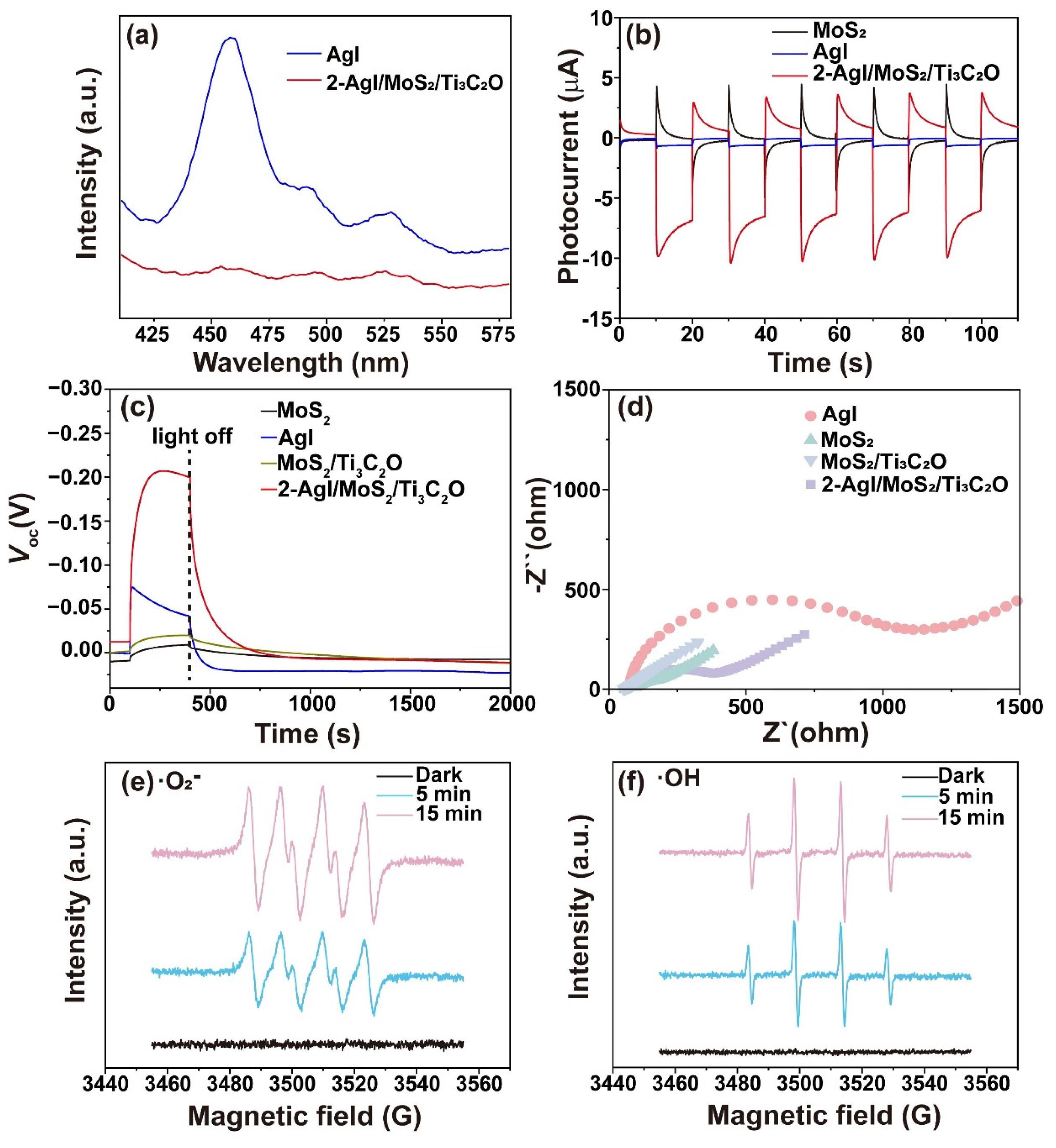
2.4.2. Carrier Transfer Performance

The separation and transportation behavior of photogenerated charges were systematically inspected in order to investigate the origin of the significantly improved photocatalytic activity of the AgI/MoS2/Ti3C2O heterojunction. The recombination efficiency of photogenerated carriers was studied by steady state photoluminescent (PL) spectra (Figure 6a). In general, electric potential energy is converted into PL emissions after the recombination of electrons and holes in the excited state. The sharply decreased PL emission of the AgI/MoS2/Ti3C2O heterojunction indicated that the recombination of photogenerated carriers was inhibited by the interfacial electric field and chemical bond. Transient photocurrent detection also displayed that AgI/MoS2/Ti3C2O exhibited the strongest photocurrent response (Figure 6b). The photoinduced carrier separation capacity of the heterojunction was further evaluated by the OCVD curves shown in Figure 6c, which demonstrate that AgI/MoS2/Ti3C2O had the strongest open-circuit voltage response. The Voc of AgI/MoS2/Ti3C2O declined slowly when the light was turned off due to the charge separation effect resulting in a longer carrier lifetime and lower carrier recombination rate. EIS spectra further uncovered that AgI/MoS2/Ti3C2O possessed excellent electrical conductivity (Figure 6d). The detection of ROS generated in the photocatalytic process was of guiding significance for the transfer direction of photoexcited carriers. Here, O2 and OH were measured by in-situ EPR signals under light excitation (Figure 6e,f). A ROS signal was apparent in the EPR spectra of AgI/MoS2/Ti3C2O under illumination, demonstrating that efficient carrier separation was responsible for the generation of abundant active species, which significantly enhanced photocatalytic activity and actively participated in pollutant degradation. The above results illustrates the vital roles that interfacial electric fields and chemical bonds played in inhibiting the rapid recombination of photoinduced excited electrons with holes and in promoting interfacial charge separation.

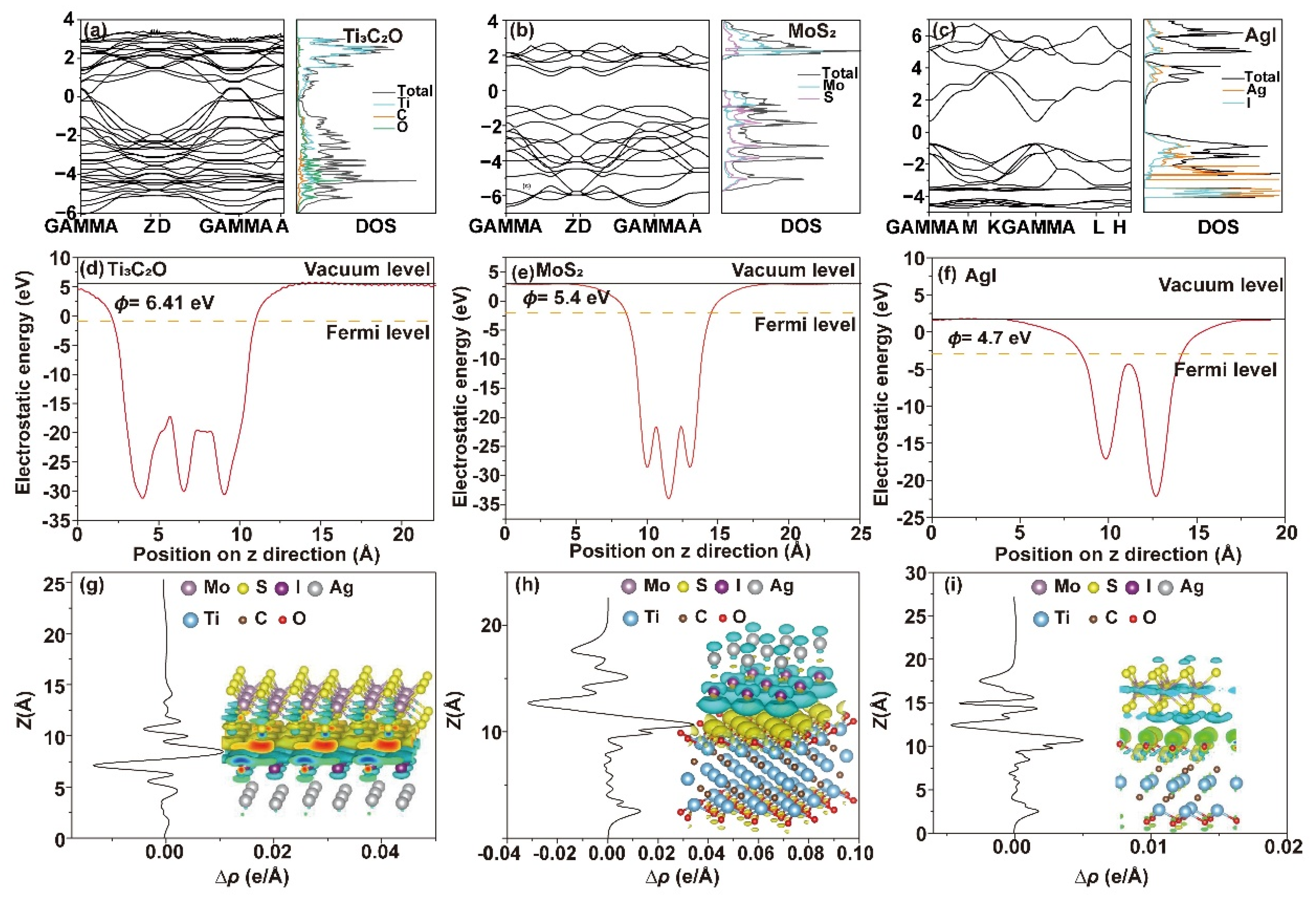
2.4.3. First-Principles Calculations

First-principles calculations based on density functional theory (DFT) were carried out to comprehensively investigate the formation of internal electric fields and the mechanism of interfacial charge transfer. Similar to the methodology employed in defect studies of Rb2O [51], our DFT approach systematically analyzed interfacial charge redistribution through the orbital-resolved density of states and work function calculations. The electronic state of Ti3C2O, which was primarily composed of Ti 3d and C 2p orbitals, spanned the Fermi level, indicating its excellent conductivity (Figure 7a). However, the electronic states of MoS2 and AgI did not distribute on the Fermi level (Figure 7b,c), indicating their limited conductivity and carrier separation efficiency. Notably, while previous studies primarily focused on point defects in bulk oxides [51], our work extends this DFT framework to interfacial chemical bonds (Ti-O-Mo), revealing their unique role as atomic-level charge transfer channels. Depending on the density of states (DOS) diagram, it could be further concluded that the VB of AgI was mainly composed of Ag 3d and I 5p orbitals, while the CB was mainly composed of Ag 5s orbitals. On the other hand, both the VB and CB of MoS2 were primarily composed of Mo 4d and S 3p orbitals. The surface Φ value was utilized to investigate the separation characteristics of interfacial charges and free electron transfer. As depicted in Figure 7d–f, Ti3C2O exhibited the largest Φ value of 6.40 eV, giving promise for the migration of space charges when it was combined with MoS2 and AgI as an electron trap. The Φ value of AgI was calculated to be 4.70 eV, distinctly smaller than that of MoS2, which was 5.70 eV. These Φ values were consistent with those derived from the UPS analysis. Φ values of Ti3C2Tx terminated with other functional groups were also calculated and are shown in Figure S7. Φ values of Ti3C2Tx with -F terminal and without functional groups were calculated to be 3.70 eV and 4.20 eV, respectively, which were lower than that of Ti3C2O synthesized in this work. Based on the calculation results, it can be seen that the Ti-O-Mo bond behaved as an atomic-level charge flow highway and accelerated the electron flux between MoS2 and Ti3C2O. Simultaneously, electrons in AgI transferred to MoS2 and Ti3C2O. The charge density difference further revealed the surface electron distribution state of the heterojunction. Significant electron transfers could be observed at the component interfaces. As shown in Figure 7g–i, after AgI was combined with MoS2 and Ti3C2O, electrons accumulated from AgI to MoS2 or Ti3C2O while holes were left on the surface. At the interface between MoS2 and Ti3C2O, electrons converged to the surface of Ti3C2O, leading to an electron accumulation layer with negative charge near the Ti3C2O side and an electron depletion layer with positive charge near the MoS2 side. The drifting of free electrons rendered the charge redistribution at the interface and resulted in the formation of an internal electric field that facilitated the separation of photogenerated electron–hole pairs.
Based on the preceding results and analysis, Scheme 1 illustrates the mechanism of charge transfer in the Z-scheme heterojunction. When AgI with a low Ef contacted MoS2 with a high Ef, free electrons migrated from AgI to MoS2 until their Ef levels were balanced, resulting in the upward bending of the band edge of AgI and the downward bending of MoS2. Simultaneously, Ti3C2O with the lowest Ef contacted tightly with MoS2 via an interfacial chemical bond and acted as an electron trap. Upon illumination, both AgI and MoS2 were excited to produce photoelectrons and holes. Interfacial electric fields and chemical bonds synergistically accelerated the transfer of photogenerated electrons from the CB of AgI to the VB of MoS2, thereby significantly enhancing the effective spatial separation of carriers and maintaining the strong redox ability of the Z-scheme heterojunction to generate abundant ROS, which greatly improved the photocatalytic performance.

3. Experimental Section

The detailed materials and apparatus are described in Supplementary Materials Sections S1 and S2.

3.1. Synthesis of AgI/MoS2/Ti3C2O Heterojunction

The synthetic process of AgI/MoS2/Ti3C2O heterojunction consisted of three steps. The first step was synthesizing Ti3C2Tx, which was prepared according to a previously reported method [52] with some modifications. The chemical etchant was prepared by slowly adding 1 g LiF into 15 mL HCl solution (9 M). Then, 5 mL distilled (DI) water was added and stirred for a while. Subsequently, 1 g Ti3AlC2 was slowly added into the prepared chemical etchant in an ice-water bath to avoid local overheating. After heating and stirring at 35 °C for 48 h, the obtained acidic solution was repeatedly washed with DI water via centrifugation at 3500 rpm for 5 min until the pH of the supernatant reached approximately neutral. Finally, multilayered Ti3C2Tx was collected via lyophilization and exfoliated by ultrasound to be few-layer.
The second step was synthesizing MoS2/Ti3C2O, which was prepared by a traditional hydrothermal method. In brief, 15 mL Ti3C2Tx (7 mg·mL−1) dispersion was evenly mixed with 242 mg Na2MoO4·2H2O and 380 mg NH2CSNH2 and then transferred into a polytetrafluoroethylene high-pressure reactor and heated at 210 °C for 24 h. The resultant product was washed with ethanol and DI water several times and lyophilized to obtain the MoS2/Ti3C2O compound. Pure MoS2 was prepared with the same method but without using Ti3C2Tx.
The last step was synthesizing AgI/MoS2/Ti3C2O Z-scheme heterojunction, which was prepared by a self-assembly method. Firstly, a certain mass of MoS2/Ti3C2O was ultrasonically dispersed into DI water. Then, 83 mg KI was slowly dropped into the dispersion solution. The mixture was treated with ultrasound for 1 h to make I be evenly distributed on the surface of MoS2/Ti3C2O. Finally, 85 mg AgNO3 was added dropwise under continuous stirring. The AgI nanoparticles (NPs) grew in situ on the surface of MoS2/Ti3C2O. The resultant product was washed with DI water and lyophilized. AgI/MoS2/Ti3C2O Z-scheme heterojunctions with different mass ratios of AgI were obtained by using different masses of MoS2/Ti3C2O (13, 30, 50, and 78 mg) and were denoted as 1-AgI/MoS2/Ti3C2O, 2-AgI/MoS2/Ti3C2O, 3-AgI/MoS2/Ti3C2O, and 4-AgI/MoS2/Ti3C2O.

3.2. Photocatalytic H2O2 Production

H2O2 production was measured by ultrasonically dispersing 10 mg photocatalyst in 100 mL ethanol solution (10 vol%). Prior to the photocatalytic reaction, the suspension was stirred in a dark room for 30 min to achieve adsorption and desorption equilibrium. The photocatalytic reaction was carried out under the irradiation of a 300 W xenon lamp configured with a simulated sunlight filter (AM1.5G). Oxygen bubbling was involved in making the suspension saturated with O2. The reactor was kept at about 10 °C using condensed water. During the photocatalytic process, 2.00 mL solution was sampled at a given time interval. After the catalyst was removed by filtrating with a 0.22 μm filter, the solution was mixed with 1 mM Ce(SO4)2 solution, which was prepared by dissolving 1 mol Ce(SO4)2 into 1 L H2SO4 solution (0.50 M). The concentration of H2O2 was obtained by indirectly measuring Ce(SO4)2 concentration depending on UV-vis spectrophotometry [53]. The absorbance of the solution was measured at 318 nm by a UV-vis spectrometer. The concentration of H2O2 was calculated from the consumption of Ce(SO4)2 in the reaction (Equations (S4) and (S5)). The linear relationship between Ce(SO4)2 concentration and UV absorption intensity is shown in Figure S8.
The apparent quantum yield (AQY) of the photocatalytic reaction was measured under the irradiation of a 300 W xenon lamp equipped with bandpass filters of 350 nm, 375 nm, 400 nm, 450 nm, and 500 nm. Typically, 10 mg AgI/MoS2/Ti3C2O Z-scheme heterojunction was dispersed into 100 mL ethanol solution (10 vol%) and then sonicated for 5 min. After 60 min of light irradiation reaction, the absorption curve of the suspension was detected by UV-vis spectrometer. The AQY value was calculated according to the following Equation (Equation (2)):
η A Q Y = N e N p × 100 % = 2 × n × N A E t o t a l E p h o t o n × 100 % = 2 × n × N A S × P × t h × c λ × 100 % = 2 × n × N A × h × c S × P × t × λ
where n is the amount of H2O2 molecules (mol), NA is the Avogadro constant (6.022 × 10²³ mol−1), h is the Planck constant (6.626 × 10⁻³⁴ J·S), c is the speed of light (3 × 10⁸ m·s−1), S is the irradiation area (cm2), P is the intensity of irradiation light (W·cm−2), t is the photoreaction time (s), and λ is the wavelength of the monochromatic light (m).

3.3. Photocatalytic Degradation of Organic Pollutants

The degradation of organic pollutants was conducted by adding 10 mg catalyst into 100 mL 10 mg·L−1 organic pollutant solution. Rhodamine B (RHB), tetracycline hydrochloride (TC), ranitidine (RAN), and sulfamethazine (SMZ) were selected as four typical organic pollutants studied in this work. The mixtures of catalyst and organic pollutant were stirred in a dark room for 30 min to achieve adsorption and desorption equilibrium. The in-situ Fenton-like degradation reaction was initiated by turning on the xenon lamp. During the degradation process, 2.00 mL solution was sampled at a given time interval. After the catalyst was removed by centrifugation, RHB, TC, and RAN concentrations were detected by UV-visible spectrophotometer, and SMZ concentrations were measured by high-performance liquid chromatography (HPLC).

3.4. Photoelectrochemical (PEC) Performance

The Mott–Schottky, electrochemical impedance spectroscopy (EIS), photoelectric response, and transient open-circuit voltage decay (OCVD) curves were performed on an electrochemical workstation (CHI 760e) coupled with a three-electrode system, which consisted of a platinum (Pt) sheet electrode (reference electrode), an Ag/AgCl electrode (counter electrode), and a piece of modified indium tin oxide (ITO) glass (working electrode). A total of 4 mg AgI/MoS2/Ti3C2O heterojunction was evenly dispersed into 1 mL ethanol by ultrasound. Then, the conductive surface of the ITO glass was modified by the suspension (25 μL) with an area of 1 cm × 1 cm for natural drying and used as the working electrode for the PEC tests. The electrolyte was 0.10 M Na2SO4 solution. EIS was performed in a solution containing 2.50 mM K3[Fe(CN)6], 2.50 mM K4[Fe(CN)6], and 0.10 M KCl.

3.5. Theoretical Calculation

In order to further study the charge-transfer characteristics of the AgI/MoS2/Ti3C2O Z-scheme heterojunction, theoretical calculations were conducted by using the Vienna abinitio simulation package (VASP) based on the density functional theory (DFT). The projector augmented wave method (PAW) was adopted together with the generalized gradient approximation (GGA) for the exchange–correlation energy functional constructed by Perdew–Burke–Ernzerhof (PBE). During the process of structure optimization, the atomic coordinates converged when the energy convergence limit was set to be 10−5 eV, and the maximum force imposed on each atom was 0.02 eV·A−1. The cutoff energy was 400 eV, and the k-point meshes of Ti3C2O and AgI were generated using VASPKIT.

4. Conclusions

In summary, a Ti3C2O-crafted AgI/MoS2 direct Z-scheme heterojunction with interfacial electric fields and chemical bonds was easily synthesized through a hydrothermal and self-assembly method. Ti3C2O MXene has a huge specific surface area and rich surface-exposed metal atoms, thereby leading to excellent light absorption and efficient carrier transport properties. The Z-type heterojunction exhibited significantly enhanced photocatalytic activity for H2O2 production and pollutant degradation compared with AgI, MoS2 and MoS2/Ti3C2O. A strong interfacial electric field was proven to be constructed, and it facilitated the vectorial transfer of photogenerated carriers from the CB of AgI to the VB of MoS2. Additionally, the interfacial Ti-O-Mo bond acted as an atomic-level channel for promoting charge migration, thereby expediting effective charge transfer between interfaces. These advantages synergistically contributed to the superb activity for high H2O2 production and efficient pollutant degradation. The synergy between electric fields and chemical bonds offers a generalizable strategy for designing high-performance heterojunction photocatalysts. Potential applications of this approach include industrial wastewater treatment and solar-driven H2O2 synthesis, addressing energy and environmental challenges.

Supplementary Materials

The following supporting information can be downloaded at: https://www.mdpi.com/article/10.3390/catal15080740/s1, Figure S1: SEM images of (a) multi-layer Ti3C2Tx; (b) few-layer Ti3C2Tx; (c) MoS2; and (d) MoS2/Ti3C2O.; Figure S: XPS survey of AgI/MoS2/Ti3C2O heterojunction.; Figure S3: (a) Photocatalytic H2O2 production of AgI/MoS2/Ti3C2O heterojunction with different mass ratios of AgI using 10% ethanol as a sacrificial agent. (b) H2O2 formation and decomposition constants derived from figure S3a.; Figure S4: XRD of AgI/MoS2/Ti3C2O before and after the reaction cycles; Figure S5: Photodegradation activity of AgI/MoS2/Ti3C2O heterojunction with different mass ratios of AgI.; Figure S6: Mott-Schottky curves of (a) MoS2 and (b) AgI.; Figure S7: Work functions of (a) Ti3C2F and (b) Ti3C2. Charge density difference Δρ(z) and their side view on interfaces between (c) AgI and Ti3C2F; (d) AgI and Ti3C2; (e) MoS2 and Ti3C2F and (f) MoS2 and Ti3C2. Yellow and cyan areas represented electron accumulation and depletion, respectively.; Figure S8: Detection of H2O2 concentration. Table S1: Comparison of H2O2 production over different photocatalysts [54,55,56,57,58].

Author Contributions

Conceptualization, S.J. and T.C.; methodology, S.J., T.C., and Y.L.; validation, J.W.; formal analysis, S.J., T.C., Y.Y., and Y.L.; data curation, S.J.; writing—original draft preparation, S.J., T.C.; writing—review and editing, T.C., Y.Y., and J.W.; supervision, J.W.; project administration, J.W.; funding acquisition, J.W. All authors have read and agreed to the published version of the manuscript.

Funding

This research was funded by the Beijing Nova Program (No. 20230484347), the Beijing Natural Science Foundation (No. 2222022), the National Natural Science Foundation of China (No. 21874120), and the Fundamental Research Funds for the Central Universities (No. 2652019112 and 2652018004). We thank the funding support from the China Scholarship Council (CSC No. 202406400014).

Data Availability Statement

The raw data supporting the conclusions of this article will be made available by the authors on request.

Acknowledgments

This research was supported by the High-performance Computing Platform of China University of Geosciences Beijing.

Conflicts of Interest

The authors declare no conflicts of interest.

References

  1. Jia, X.; Cao, J.; Sun, H.; Li, X.; Lin, H.; Chen, S. Interfacial engineering of Bi12O17Br2/g-C3N4-x S-scheme junction boosting charge transfer for cooperative tetracycline decomposition and CO2 reduction. Appl. Catal. B Environ. 2024, 343, 123522. [Google Scholar] [CrossRef]
  2. Yang, Q.; Jiang, Y.; Zhuo, H.; Mitchell, E.M.; Yu, Q. Recent progress of metal single-atom catalysts for energy applications. Nano Energy 2023, 111, 108404. [Google Scholar] [CrossRef]
  3. Vinoth, S.; Ong, W.-J.; Pandikumar, A. Defect engineering of BiOX (X = Cl, Br, I) based photocatalysts for energy and environmental applications: Current progress and future perspectives. Coord. Chem. Rev. 2022, 464, 214541. [Google Scholar] [CrossRef]
  4. He, L.; Zeng, X.; Chen, H.; Zhao, L.; Huang, Z.; Wang, D.; He, X.; Fang, W.; Du, X.; Li, W. A hybrid photocatalytic system splits atmospheric water to produce hydrogen. Adv. Funct. Mater. 2024, 34, 2313058. [Google Scholar] [CrossRef]
  5. Wang, L.; Chen, T.; Cui, Y.; Wu, J.; Zhou, X.; Xu, M.; Liu, Z.; Mao, W.; Zeng, X.; Shen, W. Rational Design of Environmentally Friendly Carbon Nanotube Embedded Artificial Vesicle-Structured Photocatalysts for Organic Pollutants Degradation. Adv. Funct. Mater. 2024, 34, 2313653. [Google Scholar] [CrossRef]
  6. Tan, D.; Zhuang, R.; Chen, R.; Ban, M.; Feng, W.; Xu, F.; Chen, X.; Wang, Q. Covalent organic frameworks enable sustainable solar to hydrogen peroxide. Adv. Funct. Mater. 2024, 34, 2311655. [Google Scholar] [CrossRef]
  7. Gong, Y.-N.; Guan, X.; Jiang, H.-L. Covalent organic frameworks for photocatalysis: Synthesis, structural features, fundamentals and performance. Coord. Chem. Rev. 2023, 475, 214889. [Google Scholar] [CrossRef]
  8. Zhu, Q.; Xu, Q.; Du, M.; Zeng, X.; Zhong, G.; Qiu, B.; Zhang, J. Recent progress of metal sulfide photocatalysts for solar energy conversion. Adv. Mater. 2022, 34, 2202929. [Google Scholar] [CrossRef]
  9. Liu, X.; Chen, T.; Xue, Y.; Fan, J.; Shen, S.; Hossain, M.S.A.; Amin, M.A.; Pan, L.; Xu, X.; Yamauchi, Y. Nanoarchitectonics of MXene/semiconductor heterojunctions toward artificial photosynthesis via photocatalytic CO2 reduction. Coord. Chem. Rev. 2022, 459, 214440. [Google Scholar] [CrossRef]
  10. Song, S.; Xing, Z.; Zhao, H.; Li, Z.; Zhou, W. Recent advances in bismuth-based photocatalysts: Environment and energy applications. Green Energy Environ. 2023, 8, 1232–1264. [Google Scholar] [CrossRef]
  11. Chen, Z.-Y.; Huang, N.-Y.; Xu, Q. Metal halide perovskite materials in photocatalysis: Design strategies and applications. Coord. Chem. Rev. 2023, 481, 215031. [Google Scholar] [CrossRef]
  12. Yu, Y.; Zeng, Q.; Tao, S.; Xia, C.; Liu, C.; Liu, P.; Yang, B. Carbon dots based photoinduced reactions: Advances and perspective. Adv Sci. 2023, 10, 2207621. [Google Scholar] [CrossRef]
  13. Tang, J.; Zhao, T.; Solanki, D.; Miao, X.; Zhou, W.; Hu, S. Selective hydrogen peroxide conversion tailored by surface, interface, and device engineering. Joule 2021, 5, 1432–1461. [Google Scholar] [CrossRef]
  14. He, K.; Huang, Z.; Chen, C.; Qiu, C.; Zhong, Y.L.; Zhang, Q. Exploring the roles of single atom in hydrogen peroxide photosynthesis. Nano-Micro Lett. 2024, 16, 23. [Google Scholar] [CrossRef] [PubMed]
  15. Jing, S.; Zhao, J.; Wang, A.; Ji, Q.; Cheng, R.; Liang, H.; Chen, F.; Kannan, P.; Brouzgou, A.; Tsiakaras, P. Efficient photocatalytic production of H2O2 and photodegradation of tetracycline by CdS/square tubular g-C3N4 S-scheme heterojunction photocatalyst. Chem. Eng. J. 2024, 479, 147150. [Google Scholar] [CrossRef]
  16. Ma, H.; Wang, Y.; Zhang, Z.; Liu, J.; Yu, Y.; Zuo, S.; Li, B. A superior ternary Z-scheme photocatalyst of Bi/Black Phosphorus nanosheets/P-doped BiOCl containing interfacial P–P bond and metallic mediator for H2O2 production and RhB degradation. Chemosphere 2023, 330, 138717. [Google Scholar] [CrossRef]
  17. Alpysbayeva, G.; Turabekov, M.; Barakhov, B.; Myrzabekov, Z.B.; Ibragimov, P.S.; Tagayev, O.; Alikhanov, K.; Narbayeva, D.; Taipova, A. Development of a disinfectant composition based on hydrogen peroxide. Eng. Sci. 2024, 28, 1080. [Google Scholar] [CrossRef]
  18. Haddadi, H.; Mokhtari, E.; Farsani, M.R.; Moghadam, A.J. Zinc substituted keggin type polyoxometalate as an effective catalyst for the oxidative desulfurization of dibenzothiophene by hydrogen peroxide as oxidant. ES Mater. Manuf. 2022, 19, 766. [Google Scholar]
  19. Chen, Z.; Yao, D.; Chu, C.; Mao, S. Photocatalytic H2O2 production systems: Design strategies and environmental applications. Chem. Eng. J. 2023, 451, 138489. [Google Scholar] [CrossRef]
  20. Hou, H.; Zeng, X.; Zhang, X. Production of hydrogen peroxide by photocatalytic processes. Angew. Chem. Int. Ed. 2020, 59, 17356–17376. [Google Scholar] [CrossRef]
  21. Chen, H.; Gao, S.; Huang, G.; Chen, Q.; Gao, Y.; Bi, J. Built-in electric field mediated S-scheme charge migration in COF/In2S3 heterojunction for boosting H2O2 photosynthesis and sterilization. Appl. Catal. B Environ. 2024, 343, 123545. [Google Scholar] [CrossRef]
  22. Chen, H.; Xing, Y.; Liu, S.; Liang, Y.; Fu, J.; Wang, L.; Wang, W. Mechanistic insights into efficient photocatalytic H2O2 production of 2D/2D g-C3N4/In2S3 photocatalyst by tracking charge flow direction. Chem. Eng. J. 2023, 462, 142038. [Google Scholar] [CrossRef]
  23. Zhang, Y.; Di, J.; Zhu, X.; Ji, M.; Chen, C.; Liu, Y.; Li, L.; Wei, T.; Li, H.; Xia, J. Chemical bonding interface in Bi2Sn2O7/BiOBr S-scheme heterojunction triggering efficient N2 photofixation. Appl. Catal. B Environ. 2023, 323, 122148. [Google Scholar] [CrossRef]
  24. Zhao, Z.; Wang, Z.; Zhang, J.; Shao, C.; Dai, K.; Fan, K.; Liang, C. Interfacial chemical bond and oxygen vacancy-enhanced In2O3/CdSe-DETA S-scheme heterojunction for photocatalytic CO2 conversion. Adv. Funct. Mater. 2023, 33, 2214470. [Google Scholar] [CrossRef]
  25. Zhu, Z.; Huang, H.; Liu, L.; Chen, F.; Tian, N.; Zhang, Y.; Yu, H. Chemically bonded α-Fe2O3/Bi4MO8Cl dot-on-plate Z-scheme junction with strong internal electric field for selective photo-oxidation of aromatic alcohols. Angew. Chem. Inter. Ed. 2022, 61, e202203519. [Google Scholar] [CrossRef] [PubMed]
  26. Deng, A.; Sun, Y.; Gao, Z.; Yang, S.; Liu, Y.; He, H.; Zhang, J.; Liu, S.; Sun, H.; Wang, S. Internal electric field in carbon nitride-based heterojunctions for photocatalysis. Nano Energy 2023, 108, 108228. [Google Scholar] [CrossRef]
  27. Chen, L.; Ren, J.T.; Yuan, Z.Y. Enabling internal electric fields to enhance energy and environmental catalysis. Adv. Energy Mater. 2023, 13, 2203720. [Google Scholar] [CrossRef]
  28. Zhu, J.; Bi, Q.; Tao, Y.; Guo, W.; Fan, J.; Min, Y.; Li, G. Mo-modified ZnIn2S4@NiTiO3 S-scheme heterojunction with enhanced interfacial electric field for efficient visible-light-driven hydrogen evolution. Adv. Funct. Mater. 2023, 33, 2213131. [Google Scholar] [CrossRef]
  29. Jiang, H.; Wang, L.; Yu, X.; Sun, L.; Li, J.; Yang, J.; Liu, Q. Precise regulation of built-in electric field over NH2-MIL-125-Ti/WO3-x S-scheme heterojunction for achieving simultaneous formation of CO and H2O2 from CO2 and H2O. Chem. Eng. J. 2023, 466, 143129. [Google Scholar] [CrossRef]
  30. Kurra, N.; Ahmed, B.; Gogotsi, Y.; Alshareef, H.N. MXene-on-paper coplanar microsupercapacitors. Adv. Energy Mater. 2016, 6, 1601372. [Google Scholar] [CrossRef]
  31. Chen, T.; Wang, Y.; Zhang, S.; Gao, Z.; Zhao, D.; Wu, J.; Shen, K.; Sun, B. Cathodic photoelectrochemical sensor developed for glutathione detection based on carrier transport in a Ti3C2Tx/AgI heterojunction. Anal. Chim. Acta 2022, 1233, 340487. [Google Scholar] [CrossRef]
  32. Fan, X.; Xu, P.; Li, Y.C.; Zhou, D.; Sun, Y.; Nguyen, M.A.T.; Terrones, M.; Mallouk, T.E. Controlled exfoliation of MoS2 crystals into trilayer nanosheets. J. Am. Chem. Soc. 2016, 138, 5143–5149. [Google Scholar] [CrossRef] [PubMed]
  33. Kwak, I.H.; Kwon, I.S.; Abbas, H.G.; Jung, G.; Lee, Y.; Park, J.; Kang, H.S. Stable methylammonium-intercalated 1T′-MoS2 for efficient electrocatalytic hydrogen evolution. J. Mater. Chem. A 2018, 6, 5613–5617. [Google Scholar] [CrossRef]
  34. Liu, J.; Liu, Y.; Xu, D.; Zhu, Y.; Peng, W.; Li, Y.; Zhang, F.; Fan, X. Hierarchical “nanoroll” like MoS2/Ti3C2Tx hybrid with high electrocatalytic hydrogen evolution activity. Appl. Catal. B Environ. 2019, 241, 89–94. [Google Scholar] [CrossRef]
  35. Tan, S.M.; Ambrosi, A.; Sofer, Z.; Huber, Š.; Sedmidubský, D.; Pumera, M. Pristine basal-and edge-plane-oriented molybdenite MoS2 exhibiting highly anisotropic properties. Chem.—Eur. J. 2015, 21, 7170–7178. [Google Scholar] [CrossRef]
  36. Hu, J.; Huang, B.; Zhang, C.; Wang, Z.; An, Y.; Zhou, D.; Lin, H.; Leung, M.K.; Yang, S. Engineering stepped edge surface structures of MoS2 sheet stacks to accelerate the hydrogen evolution reaction. Energy Environ. Sci. 2017, 10, 593–603. [Google Scholar] [CrossRef]
  37. Wang, J.; Fang, W.; Hu, Y.; Zhang, Y.; Dang, J.; Wu, Y.; Chen, B.; Zhao, H.; Li, Z. Single atom Ru doping 2H-MoS2 as highly efficient hydrogen evolution reaction electrocatalyst in a wide pH range. Appl. Catal. B Environ. 2021, 298, 120490. [Google Scholar] [CrossRef]
  38. Li, X.; Lv, X.; Sun, X.; Yang, C.; Zheng, Y.-Z.; Yang, L.; Li, S.; Tao, X. Edge-oriented, high-percentage 1T′-phase MoS2 nanosheets stabilize Ti3C2 MXene for efficient electrocatalytic hydrogen evolution. Appl. Catal. B Environ. 2021, 284, 119708. [Google Scholar] [CrossRef]
  39. Reddy, D.A.; Lee, S.; Choi, J.; Park, S.; Ma, R.; Yang, H.; Kim, T.K. Green synthesis of AgI-reduced graphene oxide nanocomposites: Toward enhanced visible-light photocatalytic activity for organic dye removal. Appl. Surf. Sci. 2015, 341, 175–184. [Google Scholar] [CrossRef]
  40. Chen, D.; Jiang, Z.; Geng, J.; Wang, Q.; Yang, D. Carbon and nitrogen co-doped TiO2 with enhanced visible-light photocatalytic activity. Ind. Eng. Chem. Res. 2007, 46, 2741–2746. [Google Scholar] [CrossRef]
  41. Liu, L.; Yang, W.; Li, Q.; Gao, S.; Shang, J.K. Synthesis of Cu2O nanospheres decorated with TiO2 nanoislands, their enhanced photoactivity and stability under visible light illumination, and their post-illumination catalytic memory. ACS Appl. Mater. Inter. 2014, 6, 5629–5639. [Google Scholar] [CrossRef]
  42. Yan, J.; Ren, C.E.; Maleski, K.; Hatter, C.B.; Anasori, B.; Urbankowski, P.; Sarycheva, A.; Gogotsi, Y. Flexible MXene/graphene films for ultrafast supercapacitors with outstanding volumetric capacitance. Adv. Funct. Mater. 2017, 27, 1701264. [Google Scholar] [CrossRef]
  43. Li, Y.; Yin, Z.; Ji, G.; Liang, Z.; Xue, Y.; Guo, Y.; Tian, J.; Wang, X.; Cui, H. 2D/2D/2D heterojunction of Ti3C2 MXene/MoS2 nanosheets/TiO2 nanosheets with exposed (001) facets toward enhanced photocatalytic hydrogen production activity. Appl. Catal. B Environ. 2019, 246, 12–20. [Google Scholar] [CrossRef]
  44. Deng, H.; Li, Z.-j.; Wang, L.; Yuan, L.-y.; Lan, J.-h.; Chang, Z.-y.; Chai, Z.-f.; Shi, W.-q. Nanolayered Ti3C2 and SrTiO3 composites for photocatalytic reduction and removal of uranium (VI). ACS Appl. Nano Mater. 2019, 2, 2283–2294. [Google Scholar] [CrossRef]
  45. Zou, X.; Zhao, X.; Zhang, J.; Lv, W.; Qiu, L.; Zhang, Z. Photocatalytic degradation of ranitidine and reduction of nitrosamine dimethylamine formation potential over MXene–Ti3C2/MoS2 under visible light irradiation. J. Hazard. Mater. 2021, 413, 125424. [Google Scholar] [CrossRef]
  46. Bhat, M.; Ranjitha, M.T.; Mamatha, S.V.; Nayak, R.; Das, R.; Roymahapatra, G. Removal of Congo red, Patton Reeder’s, and Rhodamine B dyes from aqueous solution using Tabebuiarosea peel as natural adsorbent. ES Food Agrofor. 2024, 16, 1143. [Google Scholar] [CrossRef]
  47. Tauc, J.; Grigorovici, R.; Vancu, A. Optical properties and electronic structure of amorphous germanium. Phys. Status Solidi B 1966, 15, 627–637. [Google Scholar] [CrossRef]
  48. Kubelka, P.; Munk, F. An article on optics of paint layers. Z. Tech. Phys. 1931, 12, 259–274. [Google Scholar]
  49. Ma, C.; Shi, F.; Liu, J.; Li, T.; Zhu, K.; Liu, J.; Cui, G.; Yang, D.; Xiao, J. Construction of a novel Ag/AgBr/AgI@SiO2 composite aerogel with controlled pore structure: Efficient removal of tetracycline by adsorption/photocatalysis synergism under visible light irradiation. J. Environ. Chem. Eng. 2023, 11, 110157. [Google Scholar] [CrossRef]
  50. Wang, M.; Han, X.; Zhao, Y.; Li, J.; Ju, P.; Hao, Z. Tuning size of MoS2 in MoS2/graphene oxide heterostructures for enhanced photocatalytic hydrogen evolution. J. Mater. Sci. 2018, 53, 3603–3612. [Google Scholar]
  51. Saleel Ahammad Saleel, V.P.; Eithiraj, R. Exploring point defects in Rb2O via First-Principles calculations. Eng. Sci. 2023, 24, 925. [Google Scholar]
  52. Cai, T.; Wang, L.; Liu, Y.; Zhang, S.; Dong, W.; Chen, H.; Yi, X.; Yuan, J.; Xia, X.; Liu, C. Ag3PO4/Ti3C2 MXene interface materials as a Schottky catalyst with enhanced photocatalytic activities and anti-photocorrosion performance. Appl. Catal. B Environ. 2018, 239, 545–554. [Google Scholar] [CrossRef]
  53. Wu, C.; Teng, Z.; Yang, C.; Chen, F.; Yang, H.B.; Wang, L.; Xu, H.; Liu, B.; Zheng, G.; Han, Q. Polarization engineering of covalent triazine frameworks for highly efficient photosynthesis of hydrogen peroxide from molecular oxygen and water. Adv. Mater. 2022, 34, 2110266. [Google Scholar] [CrossRef]
  54. Yang, Y.; Zeng, Z.; Zeng, G.; Huang, D.; Xiao, R.; Zhang, C.; Zhou, C.; Xiong, W.; Wang, W.; Cheng, M.; et al. Ti3C2 Mxene/porous g-C3N4 interfacial Schottky junction for boosting spatial charge separation in photocatalytic H2O2 production. Appl. Catal. B Environ. 2019, 258, 117956. [Google Scholar] [CrossRef]
  55. Yang, Y.; Cheng, B.; Yu, J.; Wang, L.; Ho, W. TiO2/In2S3 S-scheme photocatalyst with enhanced H2O2-production activity. Nano Res. 2023, 16, 4506–4514. [Google Scholar] [CrossRef]
  56. Feng, C.; Tang, L.; Deng, Y.; Wang, J.; Liu, Y.; Ouyang, X.; Yang, H.; Yu, J.; Wang, J. A novel sulfur-assisted annealing method of g-C3N4 nanosheet compensates for the loss of light absorption with further promoted charge transfer for photocatalytic production of H2 and H2O2. Appl. Catal. B Environ. 2021, 281, 119539. [Google Scholar] [CrossRef]
  57. Zhao, X.; You, Y.; Huang, S.; Wu, Y.; Ma, Y.; Zhang, G.; Zhang, Z. Z-scheme photocatalytic production of hydrogen peroxide over Bi4O5Br2/g-C3N4 heterostructure under visible light. Appl. Catal. B Environ. 2020, 278, 119251. [Google Scholar] [CrossRef]
  58. Zhao, S.; Zhao, X. Polyoxometalates-derived metal oxides incorporated into graphitic carbon nitride framework for photocatalytic hydrogen peroxide production under visible light. J. Catal. 2018, 366, 98–106. [Google Scholar] [CrossRef]
Figure 1. (a) Schematic representation of synthetic route of AgI/MoS2/Ti3C2O heterojunction; (b) HRTEM image of AgI/MoS2/Ti3C2O heterojunction; (ci) EDS images of AgI/MoS2/Ti3C2O heterojunction.
Catalysts 15 00740 g001
Figure 2. (a) Raman spectra of Ti3C2O, MoS2, MoS2/Ti3C2O, and AgI/MoS2/Ti3C2O; (b) XRD patterns of Ti3C2O, MoS2, AgI, MoS2/Ti3C2O, and AgI/MoS2/Ti3C2O; high-resolution XPS spectra of (c) C 1s: The peaks were fitted to C-C bond (red line), C-O bond (green line), C-Ti bond (blue line) and C-F bond (pink line) in Ti3C2Tx; The peak was fitted to C-C bond (pink line) in AgI/MoS2/Ti3C2O; (d) O 1s: The peaks in Ti3C2Tx (green line) were fitted to Ti-O-H (light blue line, 532.8 eV) and Ti-O-Ti (purple line, 530.3 eV); The peaks in MoS2/Ti3C2O (orange line) and AgI/MoS2/Ti3C2O (blue line) were fitted to Ti-O-H (light blue line, 532.8 eV), Ti-O-Mo (red line, 530.8 eV) and Ti-O-Ti (purple line, 530.3 eV); (e) Ti 2p: The peaks were fitted to Ti(IV) 2p3/2 (green line, 458.85 eV), Ti(IV) 2p1/2 (blue line, 464.85 eV), Ti(II) 2p3/2(red line, 455.01 eV), Ti (III) 2p3/2 (yellow line, 456.25 eV), Ti(II) 2p1/2 (pink line, 461.01 eV) and Ti (III) 2p1/2(orange line, 462.53 eV) in Ti3C2Tx; (f) Mo 3d: The peaks were fitted to Mo 3d5/2 (green line, 229.46 eV) and Mo 2d3/2 (light blue line, 232.61 eV) in AgI/MoS2/Ti3C2O; (g) S 2p: The peaks were fitted to S 2p3/2 (orange line, 162.04 eV) and S 2p1/2 (purple line, 163.25 eV); (h) Ag 3d; and (i) I 3d.
Catalysts 15 00740 g002
Figure 3. Photocatalytic H2O2 production of the as-prepared heterojunction. (a) H2O2 yield over various catalysts with 10% ethanol as a sacrificial reagent; (b) cycling runs for the photocatalytic H2O2 production over 2-AgI/MoS2/Ti3C2O; (c) H2O2 yield over 2-AgI/MoS2/Ti3C2O under different conditions; (d) AQY of 2-AgI/MoS2/Ti3C2O.
Catalysts 15 00740 g003
Figure 4. Photocatalytic degradation of various pollutants by the as-prepared heterojunction. (a) RHB, (b) TC, (c) RAN, and (d) SMZ degradation efficiency in the presence of 2-AgI/MoS2/Ti3C2O; (e) photodegradation of RHB for three cycles using 2-AgI/MoS2/Ti3C2O; (f) photodegradation of RHB with scavengers using 2-AgI/MoS2/Ti3C2O.
Catalysts 15 00740 g004
Figure 5. (a) UV/Vis DRS of MoS2, AgI, Ti3C2O, MoS2/Ti3C2O, and 2-AgI/MoS2/Ti3C2O; (b) plots of the transformed Kubelka–Munk function for AgI and MoS2; (c) UPS spectra of MoS2 and AgI; high-resolution in-situ XPS spectra of (d) Ag 3d, (e) Mo 3d, and (f) Ti 2p in 2-AgI/MoS2/Ti3C2O; (g) calculated band structure diagrams of MoS2 and AgI.
Catalysts 15 00740 g005
Figure 6. (a) PL spectra of AgI and 2-AgI/MoS2/Ti3C2O; (b) transient photocurrent response of MoS2, AgI and 2-AgI/MoS2/Ti3C2O; (c) OCVD curves of MoS2, AgI, MoS2/Ti3C2O, and 2-AgI/MoS2/Ti3C2O; (d) nyquist diagrams of MoS2, AgI, MoS2/Ti3C2O, and 2-AgI/MoS2/Ti3C2O detected in the solution containing 2.50 mM K3[Fe(CN)6], 2.50 mM K4[Fe(CN)6], and 0.10 M KCl; EPR signals of in-situ formed (e) •O2 and (f) •OH for 2-AgI/MoS2/Ti3C2O.
Catalysts 15 00740 g006
Figure 7. Calculated DOS and work functions of (a,d) Ti3C2O, (b,e) MoS2, and (c,f) AgI; charge density difference Δρ (z) and their side view on interfaces between (g) AgI and MoS2, (h) AgI and Ti3C2O, and (i) MoS2 and Ti3C2O. Yellow and cyan areas represent electron accumulation and depletion, respectively.
Catalysts 15 00740 g007
Scheme 1. Schematic representation of the charge separation and transfer at the interfaces between (a) AgI and MoS2 and (b) Ti3C2O and MoS2 before and after contact.
Catalysts 15 00740 sch001
Disclaimer/Publisher’s Note: The statements, opinions and data contained in all publications are solely those of the individual author(s) and contributor(s) and not of MDPI and/or the editor(s). MDPI and/or the editor(s) disclaim responsibility for any injury to people or property resulting from any ideas, methods, instructions or products referred to in the content.

