Article

SnBi Catalytic Grown on Copper Foam by Co-Electrodeposition for Efficient Electrochemical Reduction of CO2 to Formate

1
State Key Laboratory of Advanced Separation Membrane Materials, Tianjin Key Laboratory of Green Chemical Technology and Process Engineering, Tiangong University, Tianjin 300387, China
2
State Key Laboratory of Chemistry for NBC Hazards Protection, Beijing 100025, China
*
Authors to whom correspondence should be addressed.
Catalysts 2025, 15(8), 698; https://doi.org/10.3390/catal15080698
Submission received: 9 March 2025 / Revised: 6 June 2025 / Accepted: 17 July 2025 / Published: 22 July 2025
(This article belongs to the Section Electrocatalysis)

Abstract

The efficient electrochemical reduction of carbon dioxide to formate under mild conditions is a promising approach to mitigate the energy crisis, but requires the use of high-performance catalysts. The selectivity and activity of catalysts can be enhanced through multi-metal doping, further advancing the electrochemical reduction of CO2 to formate. This study demonstrates a co-electrodeposition strategy for synthesizing SnBi electrocatalysts on pretreated copper foam substrates, systematically evaluating how the Sn2+/Bi3+ molar ratio in the electrodeposition solution and the applied current density affect the catalytic performance for CO2-to-formate conversion. Optimal performance was achieved with a molar ratio of Sn2+ to Bi3+ of 1:0.5 and a deposition current density of 3 mA cm−2, resulting in a formate Faradaic efficiency (FEformate) of 97.80% at −1.12 V (vs. RHE) and a formate current density of 26.9 mA·cm−2. Furthermore, the Sn1Bi0.50-3 mA·cm−2 electrode demonstrated stable operation at the specified potential for 9 h, maintaining a FEformate above 90%. Compared to previously reported metal catalysts, the SnBi catalytic electrode exhibits superior performance for the electrochemical reduction of CO2 to HCOOH. The study highlights the significant impact of the metal ion molar ratio and deposition current density in the electrodeposition process on the characteristics and catalytic performance of the electrode.

1. Introduction

Since the Industrial Revolution, excessive reliance on fossil fuels has significantly increased carbon dioxide (CO2) emissions, intensifying global warming and posing severe threats to human safety and property [1]. However, CO2, an abundant and cost-effective C1 feedstock, can be transformed into high-value carbon-based chemicals such as methane, methanol, and formic acid via carbon dioxide reduction (CO2RR). We need to reduce the CO2 emission in the source. To treat atmospheric CO2 is fundamentally pointless, but we need to capture it in the sources and treat it, concentrated, adequately, for instance, by electrochemical reduction [2]. Prof. Jouny conducted a General Techno-Economic Analysis (GTEA) of CO2 electrochemical reduction systems, evaluating products such as formic acid, carbon monoxide, methanol, and ethylene. The analysis identified formic acid and carbon monoxide as the most economically advantageous products [3]. Among these, formic acid (HCOOH) holds significant value as an organic feedstock [4,5], a fuel source [6,7], and a hydrogen storage material [4,8], making it one of the most economically viable outcomes of CO2 electrochemical reduction [9]. Additionally, formic acid production involves a 2-electron reaction process, which is kinetically favorable and facilitates its selective generation [10].
Efficient CO2 activation on the electrocatalyst surface is critical to the CO2RR process. The standard reduction potential for CO2 to accept an electron and form CO2 is −1.90 V versus the Standard Hydrogen Electrode (SHE), presenting high reaction energy barriers and challenges from competitive hydrogen evolution reactions. Current catalysts often exhibit limitations in catalytic activity, selectivity, and stability [11]. Therefore, developing low-cost, high-performance catalytic electrodes through simple fabrication methods is imperative. Transition metal centers, with their abundant d-electronic configurations, can effectively interact with the frontier molecular orbitals of CO2, reducing the energy barriers for conversion. As a result, transition metal-based catalysts are among the most promising options for the electrochemical reduction of CO2 [12,13].
Numerous studies have demonstrated that combining different metals can effectively modulate the chemical environment on the catalyst surface and alter the binding strength of various reaction intermediates [14,15]. Research on polymetallic catalysts for ERCO2–HCOOH has predominantly focused on binary metal systems.
Transition metal-based catalysts, while typically electron-rich and prone to hydrogen evolution reactions (HER), can be complemented by P-block metals (Sn, In, Bi, Pb, Tl, etc.) and their oxides, which exhibit unique electronic structures that suppress competitive HER and enhance the adsorption of CO2 and ERCO2–HCOOH intermediates, leading to higher activity and selectivity in the reaction [16,17,18,19]. Among these, Sn and Bi stand out due to their low cost, non-toxicity, environmental compatibility, and abundance, demonstrating excellent performance in CO2 reduction to HCOOH [20,21,22,23]. SnOx, in particular, enhances *OCHO intermediate adsorption compared to monomeric Sn, playing a crucial role in HCOOH formation [24]. For instance, Kim et al. synthesized SnO2 nanoparticles with adjustable sub-nanometer particle spacing, achieving a formic acid Faradaic efficiency (FEHCOOH) of 81% at −1.2 V (vs. RHE) and a current density of 8 mA·cm−2 [25]. Similarly, Bi catalysts exhibit pro-oxidant properties that promote *OCHO intermediate formation from carbon dioxide anion radicals, improving HCOOH selectivity. Xie et al. prepared rhombic dodecahedral Bi catalysts exposing Bi(110) and Bi(104) crystal faces, which preferentially adsorbed *OCHO intermediates, achieving FEHCOOH values greater than 92% at potentials between −0.7 V and −1.2 V (vs. RHE) [26]. Multi-metal doping can create special interfacial structures and synergistic effects, fine-tuning the electronic structure of active sites to optimize intermediate adsorption and enhance catalytic performance [27,28,29]. The Sn-Bi interface, in particular, facilitates efficient charge transfer, strengthening the interaction with *OCHO intermediates and improving both selectivity and long-term stability [15]. For example, Yang et al. fabricated SnBi catalysts via co-electrodeposition on carbon paper, achieving a FEHCOOH of 96.4% at −1.06 V (vs. RHE) with a current density of 36.7 mA·cm−2, maintaining consistent performance over time [30].
Selecting an appropriate substrate is crucial for catalyst performance. Copper foam is an excellent choice due to its superior electrical conductivity, ductility, and cost-effectiveness [21,31]. As a metallic substrate, the strong interaction between copper foam and the catalyst can significantly regulate the surface structure and electronic state of the catalyst, enhancing both its activity and selectivity while also extending its operational lifespan [28]. Additionally, the use of copper foam improves mass transfer during the CO2 electrochemical reaction and facilitates efficient electron transfer at the interface between the substrate and the catalyst, further promoting the CO2 electrochemical reduction process [32]. The KHCO3 electrolyte plays a vital role in maintaining the CO2/HCO3 balance and stabilizing the neutral pH of the electrolyte.
In this study, SnBi bimetallic catalysts were synthesized on pretreated copper foam using electrodeposition, a straightforward and cost-effective method suitable for potential industrial applications. By optimizing the electrodeposition solution composition, including the molar ratio of metal ions and deposition current, a high-performance catalytic electrode was developed. The surface of the fabricated SnBi electrode predominantly consisted of metal oxides, demonstrating excellent performance in the electrochemical reduction of CO2 to formate (HCOO). Under electrolysis at −1.12 V (vs. RHE) for 9 h, the electrode exhibited remarkable stability, maintaining a Faraday efficiency for formic acid (FEHCOOH) above 90%. Additionally, the electrode achieved a peak FEHCOOH of 97.80% with a formic acid partial current density of 26.9 mA·cm−2.

2. Results and Discussion

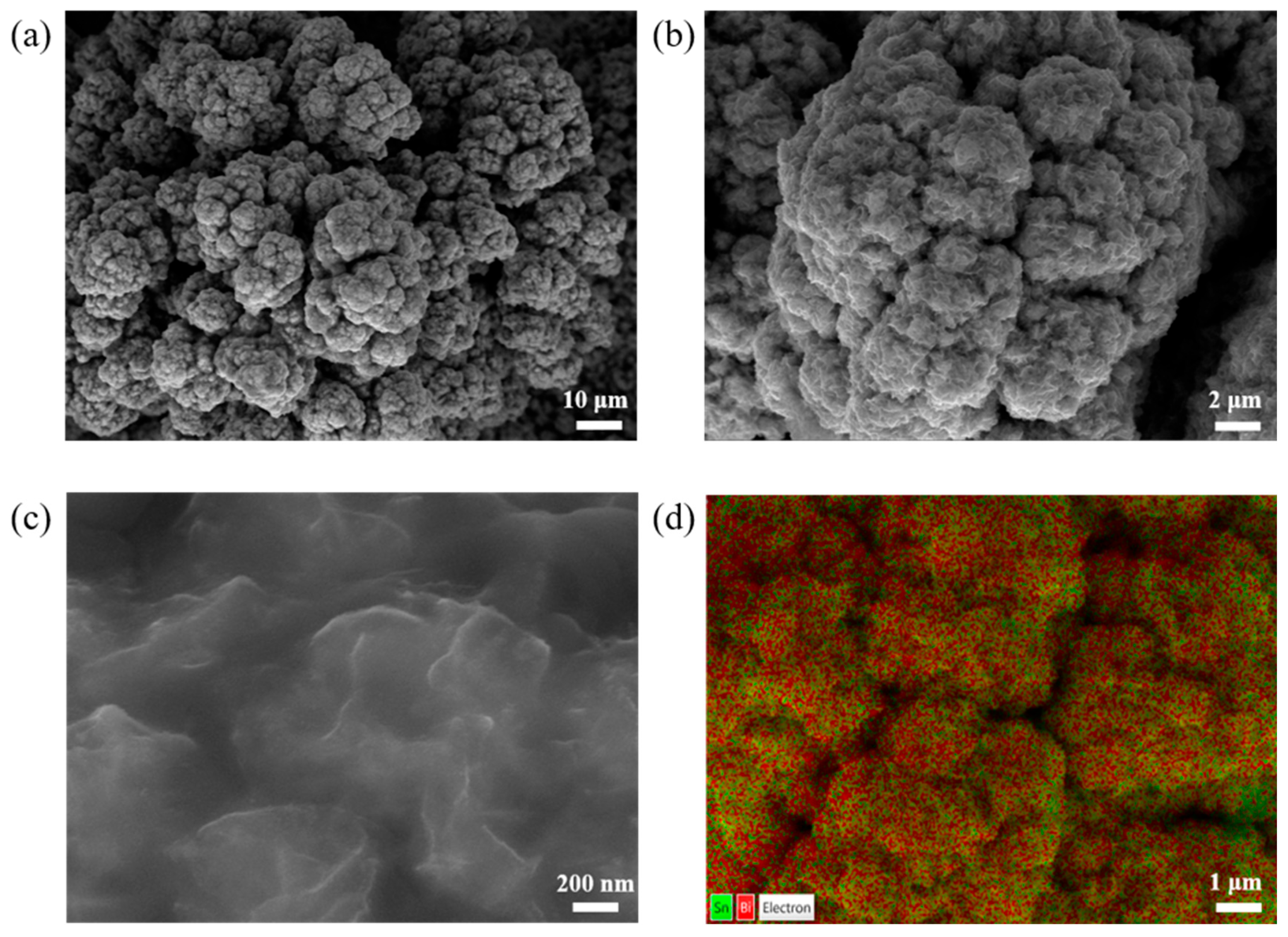
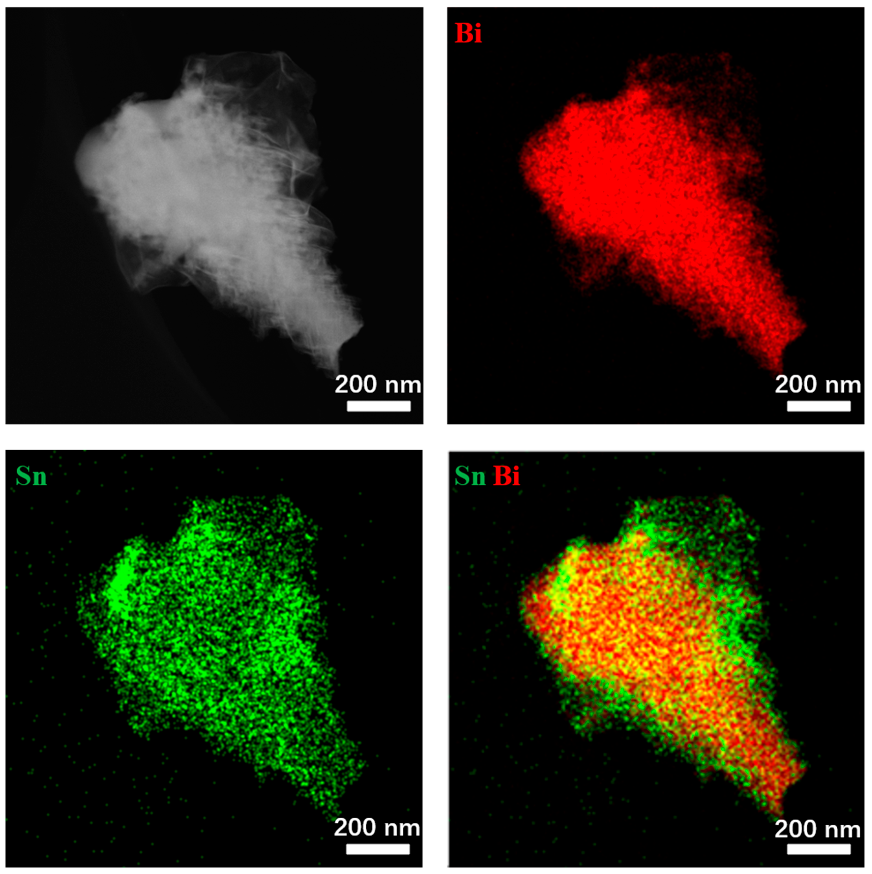
2.1. Morphological and Structural Characterization

Catalytic electrodes fabricated at varying current densities were characterized using scanning electron microscopy (SEM, Figure 1, Figures S3, S6 and S7) and transmission electron microscopy (TEM, Figure 2). The analyses confirmed the successful bonding of the SnBi catalyst to the derivatized copper foam substrate. The electrode surface exhibited a cauliflower-like morphology with vein-like structures, and as the deposition current density increased, the cauliflower-like structures became more densely packed. Elemental distribution maps (Figure 3) obtained from EDS revealed a uniform distribution of Sn and Bi across the catalytic material. Additionally, the surface Bi content decreased while Sn content increased with higher deposition current densities, indicating that elevated current densities favor Sn metal deposition.
The crystal structure of the bimetallic Sn-Bi nanostructures was analyzed using X-ray diffraction (XRD, Figure 4). Peaks observed at 27.2°, 38.0°, 39.6°, and 48.7° corresponded to the (012), (104), (110), and (202) crystal planes of metallic Bi, as referenced from the standard card (JCPDS PDF# 85–1329). Additionally, diffraction peaks at 43.3°, 50.4°, 74.1°, and 89.9° were attributed to the (111), (200), (220), and (311) planes of metallic Cu, based on the standard card (JCPDS PDF# 04–0836). These peaks originated from the derivatized copper foam substrate, as corroborated by the XRD spectra of the substrate itself.
The surface composition and chemical state of the SnBi catalytic electrode were further investigated using XPS. The Sn3d XPS spectrum (Figure 4c) showed interference from Na present in NaKC4H4O6·5H2O and Na3C6H5O7 used in the electrodeposition solution [33,34]. The analysis indicated that Sn primarily exists in oxide form, with its relevant peaks shifted towards the high-energy field. This shift aligns with the electronegativity order (Bi > Sn), implying electron transfer from Sn to Bi within the catalyst. This strong interaction between Sn and Bi metals enhances the binding of catalytically active sites to *OCHO intermediates, thereby improving catalytic activity, HCOOH selectivity, and stability [15,21,30]. Additionally, interactions between the Sn catalyst and the substrate may create a local environment conducive to the ERCO2–HCOOH reaction, further enhancing the activity and selectivity of the catalyst [28,35]. Consistent with SEM-Mapping results (Table S2), the Bi content on the electrode surface decreases as the deposition current density increases. Except for the Sn1Bi0.50-1 mA·cm−2 electrode, which displays a significant variation in the Sn and Bi elemental ratio, other electrodes exhibit relatively consistent ratios. For the Sn1Bi0.50-3 mA·cm−2 and Sn1Bi0.50-4 mA cm−2 electrodes, the Sn to Bi ratio approximates 1.5:1, with variations attributed to differences in Bi monomer and Bi2O3 content, while the active components remain unchanged. Previous studies have demonstrated that an optimal catalyst composition enhances CO2 adsorption and facilitates the generation of *OCHO intermediates, contributing to improved catalytic performance [30,36,37].
High-resolution TEM analysis of the Sn1Bi0.50-3 mA·cm−2 electrode (Figure 2) revealed lattice spacings of 0.3326 nm, 0.2369 nm, and 0.2153 nm, corresponding to the (012), (104), and (110) crystal planes of Bi, respectively, as confirmed by XRD analysis (Figure 4a). Previous research has demonstrated that these Bi crystal facets enhance localized proton activity at the electrode surface, facilitate the adsorption of carbon dioxide anion radicals, reduce free energy barriers for intermediate formation in the ERCO2–HCOOH reaction, and promote the generation of formic acid or formate [21,26,38,39]. Elemental distribution analysis using TEM–EDS (Figure 3) showed an interspersed and uniform distribution of Sn and Bi within the catalyst. When analyzed in combination with the mapping results of SEM and TEM, and the deposition current density reaches 4 mA·cm−2, Sn is mainly in an amorphous form in the SnBi electrode, and many diffraction peaks associated with the Sn crystalline surface are observed on the prepared Sn1Bi0.50-4 mA·cm−2 catalytic electrodes (Figure 1d and Figure 3).

2.2. Electrochemical Properties

2.2.1. Effect of Different Sn2+:Bi3+ Molar Ratios on Catalyst Activity

Linear sweep voltammetry (LSV) was conducted to assess the catalytic activity of the electrodes in the electrochemical reduction of CO2. As illustrated in Figure 5a, the current density exhibited significant variation across different Sn2+:Bi3+ molar ratios at the same potential within the CO2 reduction range. This difference indicates that the concentration of Bi3+ in the electrodeposition solution affects its performance in electrochemical CO2 reduction of CO2 to HCOO. The order of current density reduction was Sn1Bi0.5-4 mA·cm−2 > Sn1Bi0.33-4 mA·cm−2 > Sn1Bi0.67-4 mA·cm−2 > Sn1Bi0.16-4 mA·cm−2, indicating that the Sn1Bi0.5-4 mA-cm–2 electrode had the best CO2 reduction activity.
The electrochemically active surface area (ECSA), an essential parameter for evaluating and comparing the electrochemical activity of catalytic, was also analyzed [40]. Double layer capacitance (Cdl) is currently the most commonly used method for measuring metal oxide ECSAs. According to the relationship that ECSA is proportional to Cdl, the order of ECSA was found to be Sn1Bi0.67-4 mA·cm−2 > Sn1Bi0.5-4 mA·cm−2 > Sn1Bi0.33-4 mA·cm−2 > Sn1Bi0.16-4 mA·cm−2. The highest ECSA was observed for the Sn1Bi0.67-4 mA·cm−2 electrode, potentially indicating high catalytic activity. However, the ECSA of the Sn1Bi0.5-4 mA·cm−2 electrode was comparable to that of the Sn1Bi0.67-4 mA·cm−2 electrode, suggesting similar electrochemical activity between these two configurations.
To evaluate the impact of electrolysis potential on FEHCOOH, CO2 electrocatalytic reduction was conducted in CO2-saturated 0.5 M KHCO3 for 1 h across a potential range of −0.82 to −1.22 V (vs. RHE). As shown in Figure 5c, the FEHCOOH exhibited a volcano-like trend, with the Sn1Bi0.16-4 mA·cm−2 electrode achieving the highest FEHCOOH of 96.27% at −1.12 V (vs. RHE). At this potential, the performance order was Sn1Bi0.16-4 mA·cm−2 > Sn1Bi0.50-4 mA·cm−2 > Sn1Bi0.67-4 mA·cm−2 > Sn1Bi0.33-4 mA·cm−2. The observed trend can be attributed to the synergistic interplay between amorphous SnOx and Bi (012) crystal planes, which is critical for achieving high selectivity. When the Sn/Bi ratio deviates from the optimal composition, this synergy is disrupted, leading to performance degradation. However, at −1.02 V (vs. RHE), the Sn1Bi0.50-4 mA·cm−2 electrode demonstrated the best performance, with a FEHCOOH of 96.12% and a formic acid partial current density of 25.0 mA·cm−2. The high overpotential presented a significant kinetic barrier for the ERCO2–HCOOH reaction. Considering both LSV and FEHCOOH results, the Sn1Bi0.50-4 mA·cm−2 electrode showed optimal catalytic performance. Furthermore, all tested electrodes maintained FEHCOOH values above 90% within the potential range of −0.92 to −1.12 V (vs. RHE), attributed to the excellent Bi(012) crystallographic orientation, strong metal–catalyst interactions, and appropriate chemical composition.

2.2.2. Effect of Deposition Current Density on the Performance of SnBi Catalytic Electrode

The influence of deposition current density on the performance of SnBi catalytic electrodes was also analyzed with a fixed Sn2+:Bi3+ molar ratio.
LSV results (Figure 6a) indicated that at −1.12 V (vs. RHE), the current density order was Sn1Bi0.50-4 mA·cm−2 > Sn1Bi0.50-2 mA·cm−2 > Sn1Bi0.50-3 mA·cm−2 > Sn1Bi0.50-1 mA·cm−2, which indicates that the Sn1Bi0.50-4 mA·cm−2 electrode is more active in the ERCO2–HCOOH reaction. The DLC value increases and then decreases with increasing deposition current density (Figure 6b), ordered as Sn1Bi0.50-3 mA·cm−2 > Sn1Bi0.50-4 mA·cm−2 > Sn1Bi0.50-2 mA·cm−2 > Sn1Bi0.50-1 mA·cm−2, which is basically the same as the degree of catalyst stacking. The highest ECSA was observed for the Sn1Bi0.50-3 mA·cm−2 electrode, predicting optimal electrochemical performance.
Figure 6c,d present the Faradaic efficiencies for formic acid (FEHCOOH) and hydrogen (FEH2) at various reduction potentials for each catalytic electrode. For Sn1Bi0.50 electrodes deposited under different current densities, the FEHCOOH followed a trend of increasing and then decreasing with the rise in reduction potential. Among these, the Sn1Bi0.50-3 mA·cm−2 electrode demonstrated superior catalytic performance across all potentials, consistently achieving FEHCOOH values exceeding 90%. This indicates that a deposition current density of 3 mA·cm−2 is an optimal parameter for electrodeposition. At a potential of −1.12 V (vs. RHE), the FEHCOOH from the electrochemical reduction of CO2 ranked as Sn1Bi0.50-3 mA·cm−2 > Sn1Bi0.50-2 mA·cm−2 > Sn1Bi0.50-4 mA·cm−2 > Sn1Bi0.50-1 mA·cm−2. Notably, the Sn1Bi0.50-3 mA·cm−2 electrode achieved a maximum FEHCOOH of 97.80%, with a corresponding current density of 26.9 mA·cm−2, highlighting its exceptional catalytic efficiency and suitability for the electrochemical reduction of CO2 to formic acid.

2.3. Impedance Characteristics of SnBi Catalytic Electrodes

The principle of CO2 reduction was examined using EIS. Nyquist plots (Figure 7) were obtained by fitting equivalent circuits to the EIS data, with the corresponding fitting parameters listed in Tables S3 and S4. The resistance at the initial point represents the solution resistance, Ri, while the absolute value of the semicircle in the high-frequency region indicates the charge-transfer resistance, Rct. Copper foam, being a highly conductive substrate, enables electrodeposition methods to prepare electrodes without a binder, which facilitates rapid electron transfer between the copper foam substrate and catalyst interface [32]. As shown in Figure 7a, the Sn2+:Bi3+ molar ratio in the deposition solution did not significantly affect the Ri of the SnBi electrodes, which remained about 10 Ω, except for the Sn1Bi0.16-4 mA·cm−2 electrode, which exhibited a markedly higher Rct compared to the others. When the molar ratio of Sn2+:Bi3+ in the deposition solution was 1:0.16, the SnBi electrode showed the highest charge–transfer resistance (17.77 Ω) in the electrochemical reaction, suggesting that this electrode was less favorable for reaction kinetics, likely due to its excessive Sn content. As depicted in Figure 7b, the deposition current density influenced the Ri of the SnBi electrode, with a lesser impact on Rct. The Sn1Bi0.50-3 mA·cm−2 catalytic electrode displayed the lowest Rct (8.28 Ω), indicating that this electrode was the most favorable for reaction kinetics, facilitating the fastest charge transfer during the electrochemical reduction of CO2 to HCOOH.
The mechanistic pathway for CO2 reduction to formate is widely accepted and can be summarized as follows [21,28].
CO2(aq) + e → CO2*(ads)
CO2*(ads) + H+ → OCHO*(ads)
OCHO*(ads) + e → HCOO(ads)
HCOO(ads) → HCOO(aq)
CO2 enters the electrolyte and undergoes its first electron transfer, resulting in the formation of an adsorbed CO2* intermediate on the electrode (Equation (1)). The electrolyte then donates a proton (H+) to the CO2* intermediate, producing OCHO*, a key intermediate for adsorption (Equation (2)); the OCHO* intermediate receives a second electron from the electrode, leading to the formation of the target product, formate (Equation (3)); and finally, the adsorbed formate is released from the electrode into the electrolyte (Equation (4)). The mechanism of CO2 electroreduction on SnBi electrodes is shown in Figure 8. According to previous research, the initial electron transfer step is the rate-determining step for the catalytic reduction of CO2 on SnBi electrodes [30,37,41,42,43].

2.4. Stability of SnBi Catalytic Electrodes

The stability of the catalytic electrode is a key factor for practical applications, and the SnBi electrode′s stability during the electrochemical reduction of CO2 was evaluated using the timed-current method [21]. The Sn1Bi0.50-3 mA·cm−2 electrode, which was prepared with a molar ratio of Sn2+:Bi3+ of 1:0.50 and a deposition current density of 3 mA·cm−2, showed optimal integrated catalytic performance and was selected for the stability test. At −1.12 V (vs. RHE), the electrode maintained stability for nearly 9 h (see Figure 9). Although there was significant fluctuation in the current density after 9 h, the FEHCOOH remained stable at 94.00%, and the formic acid concentration in the electrolyte reached 0.165 mol·L−1 within the first 8 h. This suggests that the fluctuation in current density was primarily due to the accumulation of HCOOH. Throughout the 9 h stability test, the Sn1Bi0.50-3 mA·cm−2 electrode consistently exhibited an FEHCOOH above 90%, indicating that the SnBi electrode has exceptional stability.
Following the stability test, an XPS analysis was conducted to investigate the changes in the surface composition of the electrode. After the test, the Sn 3d peaks shifted toward lower binding energy, with Sn0 content increasing from 5.64% to 12.41% and SnOx content rising from 55.24% to 60.13%. The Bi0 peak in the Bi 4f spectrum shifted towards higher binding energy, while the Bi3+ peak moved to lower binding energy. The Bi0 content decreased from 27.36% to 6.37%, and Bi3+ content increased from 11.36% to 21.09% (Figure 10 and Table S5). Based on the electronegativity of Sn and Bi, it can be inferred that electrons were transferred from Bi to Sn. Since high levels of SnO and SnOx are essential for CO2 reduction, the FEHCOO remained above 90% after 9 h of electrolysis. However, the formate selectivity slightly decreased after prolonged electrolysis due to the changes in the surface composition of the SnBi electrode, the increasing formate concentration, and the formation of a pH gradient near the electrode. In CO2 reduction reactions, pH gradients can lead to catalyst degradation by affecting the CO2 concentration near the electrode [4,44]. In conclusion, the Sn1Bi0.50-3 mA·cm−2 electrode demonstrated excellent stability at −1.12 V (vs. RHE) for 8 h. These tests are preliminary and indicate good short-term stability, but longer-duration testing (e.g., hundreds or thousands of hours) is needed to assess true industrial viability.

3. Materials and Methods

3.1. Materials

L-ascorbic acid (99%) was sourced from Shanghai McLean Biochemical Technology Co. (Shanghai, China) Potassium sodium tartrate (NaKC4H4O6·5H2O, 99%), sodium citrate (Na3C6H5O7, 98%), bismuth nitrate (Bi(NO3)3·5H2O, 99%), stannous chloride (SnCl2·2H2O, 98%), and potassium bicarbonate (KHCO3, 99.5%) were obtained from Shanghai Aladdin Biochemistry and Technology Co. (Shanghai, China). Nitric acid (HNO3) was purchased from Beijing Chemical Factory Co. (Beijing, China). The copper foams used in this study were obtained from Guangjiayuan New Material Co., Ltd. (Kunshan, China) Copper foam, with a pore size range of 5–45 µm (10–130 ppi) and a porosity of 75–98%, was used as the substrate. The Nafion-117 proton exchange membrane was provided by DuPont (Shanghai, China), and graphite sheet (10 mm × 20 mm), platinum sheet electrode (20 mm × 20 mm × 0.1 mm), and Ag/AgCl reference electrode were purchased from Tianjin Gaoshi Ruilian Optoelectronic Technology Co. (Tianjin, China).

3.2. Preparation of the Pretreated Copper Foam Substrate

The original copper foam substrate (thickness: 0.3 mm) underwent a chemical pretreatment, which proceeded as follows: initially, the copper foam was cut into a 1 cm × 2 cm rectangle and immersed in a 0.1 mol L−1 HCl solution for 1 h to remove surface oxides. It was then rinsed 2–3 times with ultrapure water, and any residual moisture was absorbed using absorbent paper. The foam was subsequently immersed in anhydrous ethanol for 1 h to eliminate any remaining organic matter. Lastly, the foam was dried with air and placed in a vacuum oven at 125 °C (without vacuum) for 1 h to yield the heat-treated copper foam substrate.

3.3. Fabrication of the SnBi Double Electrode

SnBi bimetallic electrodes were prepared by co-electrodepositing SnBi catalysts onto pretreated copper foam substrates using a simple co-electrodeposition technique. A 100 mL solution of 0.1 mol L−1 HNO3 was placed in a single-compartment deposition cell and heated in a water bath at 60 °C. To this, 6 g of C6H5Na3O7, 3 g of NaKC4H4O6, and 0.5–2 g of Bi(NO3)3·5H2O were added one by one under constant stirring, and the deposition cell was removed when all components were completely dissolved. After the solution was cooled to room temperature, 0.1 g of L-type ascorbic acid and 1.4 g of SnCl2·2H2O were added in turn, and the mixture was stirred until fully dissolved to form the electrodeposition solution. The molar ratio of Sn2+:Bi3+ in the solution was 1:x, with x values of 0.16, 0.33, 0.50, and 0.67. The heat-treated copper foam was then rinsed with ultrapure water until fully wetted, lightly drained, and immersed into the prepared electrodeposition solution as the working electrode. The copper foam had a deposition area of 1 cm × 1 cm, and two graphite sheets (1 cm × 2 cm each) were used as counter electrodes, positioned 20 cm from the working electrode. A deposition current density of y mA·cm−2 (where y was 1, 2, 3, or 4) was applied for 1 h of constant current, double-sided electrodeposition at room temperature. After the deposition, the electrodes were rinsed 3–5 times with ultrapure water and dried in a vacuum oven at 60 °C for 4 h to produce the SnBi catalytic electrode. The final catalytic electrode was labeled as Sn1Bix-y mA·cm−2.

3.4. Material Characterization

Structural and chemical characterization of the catalytic electrodes was performed using multiple analytical techniques. X-ray diffraction (XRD) analysis was conducted on a SmartLab SE diffractometer (Rigaku, Tokyo, Japan) at ambient temperature, with phase identification achieved through comparison to standard reference patterns (PDF database) using Jade 6 software (version 6.2.9200). The surface chemical composition and electronic states were examined by X-ray photoelectron spectroscopy (XPS) on a Thermo Scientific K-Alpha spectrometer (Waltham, MA, USA) with monochromatic Al Kα radiation (1486.6 eV), where all binding energies were calibrated against the adventitious carbon C 1s peak at 284.8 eV. Morphological characterization and elemental mapping were carried out using scanning electron microscopy (SEM, TESCAN MIRA LMS, Brno, Czech Republic) equipped with energy-dispersive X-ray spectroscopy (EDS) capabilities.

3.5. Electrochemical Measurements

Electrochemical characterization was performed in a conventional H-type cell using a CHI660e potentiostat (CH Instruments, Shanghai, China). The cell compartments were separated by a Nafion (Singapore) 117 membrane that was pre-treated by boiling in 3% H2O2, deionized water, and 0.5 M H2SO4 (1 h each), followed by storage in 0.1 M KHCO3 to ensure complete conversion to the K+-form prior to electrochemical testing. All experiments were conducted in CO2-saturated 0.1 M KHCO3 electrolyte maintained at room temperature (25 ± 1 °C). A platinum sheet was employed as the counter electrode, and an Ag/AgCl electrode saturated with KCl served as the reference electrode. Each compartment contained 50 mL of 0.5 M KHCO3 solution, which was saturated with CO2 for 30 min prior to electrochemical testing. Gas flow rate: 20 mL·min−1. Potentials referenced to RHE (calculated using Equation (5)).
E (vs. RHE) = E (vs. Ag/AgCI) + 0.197 + 0.059 × pH
The pH of the CO2-saturated 0.5 M KHCO3 solution was 7.4, and all experiments were conducted at 25 °C under ambient pressure.
Electrochemical measurements were conducted in a standard H-type cell. During the experiments, CO2 was continuously bubbled into the catholyte (0.5 M KHCO3 solution). Linear sweep voltammetry (LSV) was performed from −0.4 to −1.6 V vs. RHE at a scan rate of 50 mV·s−1. Argon (Ar) was used as a reference gas for CO2 reduction, and the initial LSV measurements were carried out under N2-saturated conditions. During the experiment, the N2 gas flow was first stopped, followed by LSV measurements under CO2-saturated conditions. Subsequently, cyclic voltammetry (CV) tests were conducted within a potential window of 0.19–0.29 V (vs. RHE) at scan rates of 40, 80, 120, 160, and 200 mV·s−1, respectively. The Cdl was calculated from the slope of the scan rate versus the redox current. Electrochemical impedance spectroscopy (EIS) was employed to evaluate the impedance effects on CO2 reduction performance. The measurements were conducted with an AC amplitude of [X] mV (if applicable) across a frequency range of 0.1 Hz to 100 kHz at a fixed potential of −0.72 V vs. RHE. Amperometric i-t curves were recorded at various potentials (−0.82, −0.92, −1.02, −1.12, and −1.22 VRHE) for 1 h to evaluate the CO2 electroreduction performance of the materials.

3.6. Product Analysis

The liquid-phase products were quantified using ion chromatography (Dionex ICS-600, Sunnyvale, CA, USA), with all samples being 100-fold diluted with ultrapure water prior to analysis. The Faradaic efficiency for HCOO (FEHCOO−) was calculated using Equation (6), which is based on the requirement of two electrons to produce one HCOO.
F H H C O O % = 2 × n × F Q
The parameters in the equation are defined as follows:
  • F—Faraday constant (96,485 C·mol−1);
  • n—amount of formate ions produced (mol);
  • Q—total charge passed through the system during the specified reaction time (C).
Gas product analysis was performed using a gas chromatograph (GC-9720 plus, Wenling, China) equipped with a thermal conductivity detector (TCD), with high-purity argon (Ar) as the carrier gas. Gas samples collected from the cathode chamber outlet were automatically injected into the GC system for analysis. The Faradaic efficiency of gaseous products was calculated using Equation (7).
F H g a s % = N × c × υ × t V m × F Q
Definition of parameters in the equation:
  • N—Number of electrons transferred per mole of CO2 converted to H2, CO, or other gaseous products (mol e/mol CO2);
  • c—Volume percentage of the target gas in the total gas mixture (%);
  • υ—CO2 flow rate at the H-cell outlet (measured by gas flow meter, mL·min−1);
  • t—Electrolysis duration (min);
  • Vm—Molar volume of gas (at standard conditions: 22.4 L·mol−1).

4. Conclusions

Catalytic electrodes of SnBi were deposited onto copper foam substrates through a straightforward electrodeposition method using solutions with varying Sn2+:Bi3+ molar ratios and deposition current densities. This study explores the effects of these factors on electrode morphology, composition, capacitance, impedance, current, and Faradaic efficiency. A correlation between the electrodeposition solution′s formulation and the electrode′s composition and performance is established, offering theoretical and experimental guidance for the controlled growth of binary metal catalysts on Cu substrates. The electrode prepared with a Sn2+:Bi3+ molar ratio of 1:0.5 and deposition current density of 3 mA·cm−2 achieved an FEHCOO of 97.80% and a formic acid current density of 26.9 mA·cm−2 at −1.12 VRHE. Stability tests demonstrated promising performance, with FEHCOO– remaining above 90% for 8 h at −1.12 VRHE. Fluctuations in current density were attributed to changes in the electrolyte. Therefore, the electrolyte needs to be constantly replaced to maintain the high activity and selectivity of the catalyst in converting CO2 to HCOO. In addition, the results show that keeping the electrolyte stable is very important to maintain the stability of the electrochemical process. Polymetallic catalysts are promising CO2 catalysts, but further refinement is needed to ensure synergistic effects between the components. Additionally, the influence of electrolyte variation on the catalyst during CO2 electroreduction warrants further investigation.

Supplementary Materials

The following supporting information can be downloaded at https://www.mdpi.com/article/10.3390/catal15080698/s1, Figure S1. SEM images of the Sn1Bi0.16-4 mA·cm−2 electrode with scale bars: (a) 10 μm, (b) 2 μm, and (c) 200 nm. (d) Elemental mapping (Bi in red and Sn in green); Figure S2. SEM images of the Sn1Bi0.33-4 mA·cm−2 electrode with scale bars: (a) 10 μm, (b) 2 μm, and (c) 200 nm. (d) Elemental mapping (Bi in red and Sn in green); Figure S3. SEM images of the Sn1Bi0.50-4 mA·cm−2 electrode with scale bars: (a) 10 μm, (b) 2 μm, and (c) 200 nm. (d) Elemental mapping (Bi in red and Sn in green); Figure S4. SEM images of the Sn1Bi0.67-4 mA·cm−2 electrode with scale bars: (a) 10 μm, (b) 2 μm, and (c) 200 nm. (d) Elemental mapping (Bi in red and Sn in green); Figure S5. Characterization of various Sn1Bix-4 mA·cm−2 electrodes: (a) XRD patterns, (b) XPS spectra, (c) XPS spectra of Sn 3d, and (d) XPS spectra of Bi 4f; Figure S6. SEM images of the Sn1Bi0.50-1 mA·cm−2 electrode with scale bars: (a) 10 μm, (b) 2 μm, and (c) 200 nm. (d) Elemental mapping (Bi in red and Sn in green); Figure S7. SEM images of the Sn1Bi0.50-2 mA·cm−2 electrode with scale bars: (a) 10 μm, (b) 2 μm, and (c) 200 nm. (d) Elemental mapping (Bi in red and Sn in green); Table S1. Proportion of microscopic surface elements of Sn1Bix-4 mA·cm−2 electrode prepared with different Sn2+:Bi3+ molar ratios; Table S2. Proportion of microsurface elements of Sn1Bi0.50-y mA·cm−2 electrode prepared by different deposition current densities; Table S3. Equivalent circuit fitting parameters of Sn1Bix-y mA·cm−2 electrodes prepared with different Sn2+:Bi3+ molar ratios; Table S4. Equivalent circuit fitting parameters of Sn1Bi0.50-y mA·cm−2 electrodes prepared with different deposition current densities; Table S5. Proportion of microsurface elements before and after reaction of Sn1Bi0.50-3 mA·cm−2 electrode.

Author Contributions

Conceptualization, L.L.; methodology, Z.L. and H.X.; validation, Z.L. and H.X.; formal analysis, A.M.; investigation Z.L., H.X. and L.L.; resources, C.W.; data curation, Z.L., H.X., J.X. and X.L.; writing—original draft preparation, Z.L.; writing—review and editing, L.L. and A.M.; visualization, Z.L.; supervision, Z.L. and H.X.; project administration, L.L.; funding acquisition, C.W.; All authors have read and agreed to the published version of the manuscript.

Funding

This research received no external funding.

Data Availability Statement

Data are contained within the article and the Supplementary Materials.

Conflicts of Interest

The authors declare no conflicts of interest.

References

  1. World Health Organization. Who Ambient Air Quality Database, 2022 Update: Status Report; World Health Organization: Geneva, Switzerland, 2023; p. 44. [Google Scholar]
  2. Nwabara, U.O.; Cofell, E.R.; Verma, S.; Negro, E.; Kenis, P.J. Durable Cathodes and Electrolyzers for the Efficient Aqueous Electrochemical Reduction of CO2. ChemSusChem 2020, 13, 855–875. [Google Scholar] [CrossRef]
  3. Jouny, M.; Luc, W.; Jiao, F. General Techno-Economic Analysis of CO2 Electrolysis Systems. Ind. Eng. Chem. Res. 2018, 57, 2165–2177. [Google Scholar] [CrossRef]
  4. Duarah, P.; Haldar, D.; Yadav, V.S.K.; Purkait, M.K. Progress in the Electrochemical Reduction of CO2 to Formic Acid: A Review on Current Trends and Future Prospects. J. Environ. Chem. Eng. 2021, 9, 106394. [Google Scholar] [CrossRef]
  5. Bulushev, D.A.; Ross, J.R. Towards Sustainable Production of Formic Acid. ChemSusChem 2018, 11, 821–836. [Google Scholar] [CrossRef] [PubMed]
  6. Ma, Z.N.; Legrand, U.; Pahija, E.; Tavares, J.R.; Boffito, D.C. From CO2 to Formic Acid Fuel Cells. Ind. Eng. Chem. Res. 2021, 60, 803–815. [Google Scholar] [CrossRef]
  7. Díaz-Sainz, G.; Alvarez-Guerra, M.; Avila-Bolívar, B.; Solla-Gullón, J.; Montiel, V.; Irabien, A. Improving Trade-Offs in the Figures of Merit of Gas-Phase Single-Pass Continuous CO2 Electrocatalytic Reduction to Formate. Chem. Eng. J. 2021, 405, 126965. [Google Scholar] [CrossRef]
  8. Onishi, N.; Iguchi, M.; Yang, X.C.; Kanega, R.; Kawanami, H.; Xu, Q.; Himeda, Y. Development of Effective Catalysts for Hydrogen Storage Technology Using Formic Acid. Adv. Energy Mater. 2019, 9, 1801275. [Google Scholar] [CrossRef]
  9. Gong, Q.; Ding, P.; Xu, M.; Zhu, X.; Wang, M.; Deng, J.; Ma, Q.; Han, N.; Zhu, Y.; Lu, J.; et al. Structural Defects on Converted Bismuth Oxide Nanotubes Enable Highly Active Electrocatalysis of Carbon Dioxide Reduction. Nat. Commun. 2019, 10, 2807. [Google Scholar] [CrossRef]
  10. Jin, S.; Hao, Z.M.; Zhang, K.; Yan, Z.H.; Chen, J. Advances and Challenges for the Electrochemical Reduction of CO2 to CO: From Fundamentals to Industrialization. Angew. Chem.-Int. Ed. 2021, 60, 20627–20648. [Google Scholar] [CrossRef]
  11. Perry, S.C.; Leung, P.K.; Wang, L.; de León, C.P. Developments on Carbon Dioxide Reduction: Their Promise, Achievements, and Challenges. Curr. Opin. Electrochem. 2020, 20, 88–98. [Google Scholar] [CrossRef]
  12. Yang, Z.W.; Chen, J.M.; Qiu, L.Q.; Xie, W.J.; He, L.N. Molecular Engineering of Metal Complexes for Electrocatalytic Carbon Dioxide Reduction: From Adjustment of Intrinsic Activity to Molecular Immobilization. Angew. Chem.-Int. Ed. 2022, 61, e202205301. [Google Scholar] [CrossRef]
  13. Nguyen, T.N.; Salehi, M.; Le, Q.V.; Seifitokaldani, A.; Dinh, C.T. Fundamentals of Electrochemical CO2 Reduction on Single-Metal-Atom Catalysts. ACS Catal. 2020, 10, 10068–10095. [Google Scholar] [CrossRef]
  14. Zhang, M.L.; Zhang, Z.D.; Zhao, Z.H.; Huang, H.; Anjum, D.H.; Wang, D.S.; He, J.H.; Huang, K.W. Tunable Selectivity for Electrochemical CO2 Reduction by Bimetallic Cu-Sn Catalysts: Elucidating the Roles of Cu and Sn. ACS Catal. 2021, 11, 11103–11108. [Google Scholar] [CrossRef]
  15. Wen, G.B.; Lee, D.U.; Ren, B.H.; Hassan, F.M.; Jiang, G.P.; Cano, Z.P.; Gostick, J.; Croiset, E.; Bai, Z.Y.; Yang, L.; et al. Orbital Interactions in Bi-Sn Bimetallic Electrocatalysts for Highly Selective Electrochemical CO2 Reduction toward Formate Production. Adv. Energy Mater. 2018, 8, 1802427. [Google Scholar] [CrossRef]
  16. Chen, F.R.; Yao, Z.C.; Lyu, Z.H.; Fu, J.J.; Zhang, X.L.; Hu, J.S. Recent Advances in P-Block Metal Chalcogenide Electrocatalysts for High-Efficiency CO2 Reduction. Escience 2024, 4, 100172. [Google Scholar] [CrossRef]
  17. Su, J.; Liu, Y.; Song, Y.; Huang, L.; Guo, W.; Cao, X.; Dou, Y.; Cheng, L.; Li, G.; Hu, Q.J. Recent Development of Nanomaterials for Carbon Dioxide Electroreduction. SmartMat 2022, 3, 35–53. [Google Scholar] [CrossRef]
  18. Yang, Z.N.; Oropeza, F.E.; Zhang, K.H.L. P-Block Metal-Based (Sn, In, Bi, Pb) Electrocatalysts for Selective Reduction of CO2 to Formate. APL Mater. 2020, 8, 060901. [Google Scholar] [CrossRef]
  19. Li, P.F.; Yang, F.Q.; Li, J.; Zhu, Q.; Xu, J.W.; Loh, X.J.; Huang, K.W.; Hu, W.P.; Lu, J. Nanoscale Engineering of P-Block Metal-Based Catalysts toward Industrial-Scale Electrochemical Reduction of CO2. Adv. Energy Mater. 2023, 13, 2301597. [Google Scholar] [CrossRef]
  20. Chen, W.; Wang, Y.; Li, Y.; Li, C. Electrocatalytic CO2 Reduction over Bimetallic Bi-Based Catalysts: A Review. CCS Chem. 2022, 5, 544–567. [Google Scholar] [CrossRef]
  21. Wang, Y.H.; Jiang, W.J.; Yao, W.; Liu, Z.L.; Liu, Z.; Yang, Y.; Gao, L.Z. Advances in Electrochemical Reduction of Carbon Dioxide to Formate over Bismuth-Based Catalysts. RARE Met. 2021, 40, 2327–2353. [Google Scholar] [CrossRef]
  22. Proietto, F.; Patel, U.; Galia, A.; Scialdone, O. Electrochemical Conversion of CO2 to Formic Acid Using a Sn Based Electrode: A Critical Review on the State-of-the-Art Technologies and Their Potential. Electrochim. Acta 2021, 389, 138753. [Google Scholar] [CrossRef]
  23. Cheng, F.; Zhang, X.; Mu, K.; Ma, X.; Jiao, M.; Wang, Z.; Limpachanangkul, P.; Chalermsinsuwan, B.; Gao, Y.; Li, Y.; et al. Recent Progress of Sn-Based Derivative Catalysts for Electrochemical Reduction of CO2. Energy Technol. 2021, 9, 2000799. [Google Scholar] [CrossRef]
  24. Li, J.; Jiao, J.Q.; Zhang, H.C.; Zhu, P.; Ma, H.F.; Chen, C.; Xiao, H.; Lu, Q. Two-Dimensional SnO2 Nanosheets for Efficient Carbon Dioxide Electroreduction to Formate. ACS Sustain. Chem. Eng. 2020, 8, 4975–4982. [Google Scholar] [CrossRef]
  25. Kim, M.K.; Lee, H.; Won, J.H.; Sim, W.; Kang, S.J.; Choi, H.; Sharma, M.; Oh, H.S.; Ringe, S.; Kwon, Y.; et al. Design of Less Than 1 Nm Scale Spaces on SnO2 Nanoparticles for High-Performance Electrochemical CO2 Reduction. Adv. Funct. Mater. 2022, 32, 2107349. [Google Scholar] [CrossRef]
  26. Xie, H.; Zhang, T.; Xie, R.; Hou, Z.; Ji, X.; Pang, Y.; Chen, S.; Titirici, M.M.; Weng, H.; Chai, G. Facet Engineering to Regulate Surface States of Topological Crystalline Insulator Bismuth Rhombic Dodecahedrons for Highly Energy Efficient Electrochemical CO2 Reduction. Adv. Mater. 2021, 33, 2008373. [Google Scholar] [CrossRef] [PubMed]
  27. Wang, X.-Q.; Chen, Q.; Zhou, Y.-J.; Li, H.-M.; Fu, J.-W.; Liu, M. Cu-Based Bimetallic Catalysts for CO2 Reduction Reaction. Adv. Sens. Energy Mater. 2022, 1, 100023. [Google Scholar] [CrossRef]
  28. Zhang, Y.X.; Li, F.L.; Dong, J.; Jia, K.C.; Sun, T.T.; Xu, L.B. Recent Advances in Designing Efficient Electrocatalysts for Electrochemical Carbon Dioxide Reduction to Formic Acid/Formate. J. Electroanal. Chem. 2023, 928, 117018. [Google Scholar] [CrossRef]
  29. Avila-Bolívar, B.; Montiel, V.; Solla-Gullón, J. Electrochemical Reduction of CO2 to Formate on Nanoparticulated Bi-Sn-Sb Electrodes. Chemelectrochem 2022, 9, e202200272. [Google Scholar] [CrossRef]
  30. Yang, S.P.; Sun, Y.; Wang, C.L.; Lv, L.; Hu, M.X.; Jin, J.S.; Xie, H.X. One-Step Co-Electrodeposition of SnBi for Efficient Electrochemical Reduction of Carbon Dioxide to Formic Acid. Catal. Sci. Technol. 2023, 13, 758–766. [Google Scholar] [CrossRef]
  31. Zheng, W.R.; Liu, M.J.; Lee, L.Y.S. Best Practices in Using Foam-Type Electrodes for Electrocatalytic Performance Benchmark. ACS Energy Lett. 2020, 5, 3260–3264. [Google Scholar] [CrossRef]
  32. Zhu, C.Q.; Wang, Q.N.; Wu, C. Rapid and Scalable Synthesis of Bismuth Dendrites on Copper Mesh as a High-Performance Cathode for Electroreduction of CO2 to Formate. J. CO2 Util. 2020, 36, 96–104. [Google Scholar] [CrossRef]
  33. Chen, Z.; Löber, M.; Rokicińska, A.; Ma, Z.; Chen, J.; Kuśtrowski, P.; Meyer, H.-J.; Dronskowski, R.; Slabon, A. Increased Photocurrent of CuWO4 Photoanodes by Modification with The Oxide Carbodiimide Sn2O(NCN). Dalton Trans. 2020, 49, 3450–3456. [Google Scholar] [CrossRef] [PubMed]
  34. Dong, W.J.; Li, R.Z.; Xu, J.J.; Tang, Y.F.; Huang, F.Q. Long-Life and High Volumetric Capacity Bi2Sn2O7 Anode with Interpenetrating Bi-O and Sn-O Networks. Cell Rep. Phys. Sci. 2022, 3, 101109. [Google Scholar] [CrossRef]
  35. Sheng, B.B.; Cao, D.F.; Liu, C.J.; Chen, S.M.; Song, L. Support Effects in Electrocatalysis and Their Synchrotron Radiation-Based Characterizations. J. Phys. Chem. Lett. 2021, 12, 11543–11554. [Google Scholar] [CrossRef] [PubMed]
  36. Wang, X.S.; Wang, W.H.; Zhang, J.Q.; Wang, H.Z.; Yang, Z.X.; Ning, H.; Zhu, J.X.; Zhang, Y.L.; Guan, L.; Teng, X.L.; et al. Carbon Sustained SnO2-Bi2O3 Hollow Nanofibers as Janus Catalyst for High-Efficiency CO2 Electroreduction. Chem. Eng. J. 2021, 426, 131867. [Google Scholar] [CrossRef]
  37. Lou, W.S.; Peng, L.W.; He, R.N.; Liu, Y.Y.; Qiao, J.L. CuBi Electrocatalysts Modulated to Grow on Derived Copper Foam for Efficient CO2-to-Formate Conversion. J. Colloid Interface Sci. 2022, 606, 994–1003. [Google Scholar] [CrossRef]
  38. Zhang, Y.; Zhang, R.; Chen, F.F.; Zhang, F.F.; Liu, Y.D.; Hao, X.Y.; Jin, H.K.; Zhang, X.H.; Lu, Z.M.; Dong, H.; et al. Mass-Transfer-Enhanced Hydrophobic Bi Microsheets for Highly Efficient Electroreduction of CO2 to Pure Formate in a Wide Potential Window. Appl. Catal. B-Environ. Energy 2023, 322, 122127. [Google Scholar] [CrossRef]
  39. Peng, C.; Yang, S.T.; Luo, G.; Yan, S.; Chen, N.; Zhang, J.B.; Chen, Y.S.; Wang, X.C.; Wang, Z.Q.; Wei, W.; et al. Ampere-Level CO2-to-Formate Electrosynthesis Using Highly Exposed Bismuth(110) Facets Modified with Sulfur-Anchored. Chem 2023, 9, 2830–2840. [Google Scholar] [CrossRef]
  40. Wei, C.; Sun, S.N.; Mandler, D.; Wang, X.; Qiao, S.Z.; Xu, Z.C.J. Approaches for Measuring the Surface Areas of Metal Oxide Electrocatalysts for Determining their Intrinsic Electrocatalytic Activity. Chem. Soc. Rev. 2019, 48, 2518–2534. [Google Scholar] [CrossRef]
  41. Wang, J.G.; Zou, J.S.; Hu, X.; Ning, S.L.; Wang, X.J.; Kang, X.W.; Chen, S.W. Heterostructured Intermetallic CuSn Catalysts: High Performance Towards the Electrochemical Reduction of CO2 to Formate. J. Mater. Chem. A 2019, 7, 27514–27521. [Google Scholar] [CrossRef]
  42. Wang, J.; Ji, Y.J.; Shao, Q.; Yin, R.G.; Guo, J.; Li, Y.Y.; Huang, X.Q. Phase and Structure Modulating of Bimetallic CuSn Nanowires Boosts Electrocatalytic Conversion of CO2. Nano Energy 2019, 59, 138–145. [Google Scholar] [CrossRef]
  43. Peng, L.W.; Wang, Y.F.; Wang, Y.X.; Xu, N.N.; Lou, W.S.; Liu, P.X.; Cai, D.Q.; Huang, H.T.; Qiao, J.L. Separated Growth of Bi-Cu Bimetallic Electrocatalysts on Defective Copper Foam for Highly Converting CO2 to Formate with Alkaline Anion-Exchange Membrane Beyond KHCO3 Electrolyte. Appl. Catal. B-Environ. 2021, 288, 120003. [Google Scholar] [CrossRef]
  44. Chen, J.Y.; Wang, L. Effects of the Catalyst Dynamic Changes and Influence of the Reaction Environment on the Performance of Electrochemical CO2 Reduction. Adv. Mater. 2022, 34, 2103900. [Google Scholar] [CrossRef]
Figure 1. SEM images of the Sn1Bi0.5-3 mA·cm−2 electrode with scale bars: (a) 10 μm, (b) 2 μm, and (c) 200 nm. (d) Elemental mapping (Bi in red and Sn in green).
Catalysts 15 00698 g001
Figure 2. High-resolution TEM images of the Sn1Bi0.5-3 mA·cm−2 electrode with the scale bars of (ac) 5 nm and (df) 1nm.
Catalysts 15 00698 g002
Figure 3. TEM mapping images of the Sn1Bi0.5-3 mA·cm−2 electrode.
Catalysts 15 00698 g003
Figure 4. Characterization of various Sn1Bi0.5-y mA·cm−2 electrodes: (a) XRD patterns, (b) XPS spectra, (c) XPS spectra of Sn 3d, and (d) XPS spectra of Bi 4f.
Catalysts 15 00698 g004
Figure 5. Electrochemical analysis of various Sn1Bix-4 mA·cm−2 electrodes: (a) LSV, (b) DLC, (c) FEHCOOH, and (d) FEH2.
Catalysts 15 00698 g005
Figure 6. Electrochemical behavior of Sn1Bi0.50-y mA·cm−2 electrodes: (a) LSV, (b) DLC, (c) FEHCOOH, and (d) FEH2.
Catalysts 15 00698 g006
Figure 7. Nyquist plots for SnBi catalytic electrodes: (a) Sn1Bix-4 mA·cm−2 electrodes and (b) Sn1Bi0.50-y mA·cm−2 electrodes.
Catalysts 15 00698 g007
Figure 8. Mechanism of CO2 electroduction on the SnBi electrodes.
Catalysts 15 00698 g008
Figure 9. Stability test results for the Sn1Bi0.50-3 mA·cm−2 electrode.
Catalysts 15 00698 g009
Figure 10. XPS spectra of the Sn1Bi0.50-3 mA·cm−2 electrode before and after the stability test: (a) XPS spectra of Sn 3d and (b) XPS spectra of Bi 4f.
Catalysts 15 00698 g010
Disclaimer/Publisher’s Note: The statements, opinions and data contained in all publications are solely those of the individual author(s) and contributor(s) and not of MDPI and/or the editor(s). MDPI and/or the editor(s) disclaim responsibility for any injury to people or property resulting from any ideas, methods, instructions or products referred to in the content.

