Article

Application of Fused Filament Fabrication in Preparation of Ceramic Monolithic Catalysts for Oxidation of Gaseous Mixture of Volatile Aromatic Compounds

Faculty of Chemical Engineering and Technology, University of Zagreb, Marulićev trg 19, 10000 Zagreb, Croatia
*
Authors to whom correspondence should be addressed.
Catalysts 2025, 15(7), 677; https://doi.org/10.3390/catal15070677
Submission received: 6 June 2025 / Revised: 4 July 2025 / Accepted: 9 July 2025 / Published: 11 July 2025
(This article belongs to the Section Catalytic Reaction Engineering)

Abstract

The aim of this work was the preparation of ceramic monolithic catalysts for the catalytic oxidation of gaseous mixture of benzene, toluene, ethylbenzene and o-xylene BTEX. The possibility of using zirconium dioxide (ZrO2) as a filament for the fabrication of 3D-printed ceramic monolithic carriers was investigated using fused filament fabrication. A mixed manganese and iron oxide, MnFeOx, was used as the catalytically active layer, which was applied to the monolithic substrate by wet impregnation. The approximate geometric surface area of the obtained carrier was determined to be 53.4 cm2, while the mass of the applied catalytically active layer was 50.3 mg. The activity of the prepared monolithic catalysts for the oxidation of BTEX was tested at different temperatures and space times. The results obtained were compared with those obtained with commercial monolithic catalysts made of ceramic cordierite with different channel dimensions, and with monolithic catalysts prepared by stereolithography. In the last part of the work, a kinetic analysis and the modeling of the monolithic reactor were carried out, comparing the experimental results with the theoretical results obtained with the 1D pseudo-homogeneous and 1D heterogeneous models. Although both models could describe the investigated experimental system very well, the 1D heterogeneous model is preferable, as it takes into account the heterogeneity of the reaction system and therefore provides a more realistic description.

1. Introduction

The Earth’s atmosphere contains over 500 different volatile organic compounds (VOCs), which include a variety of organic compounds with a boiling point below 250 °C and a saturated vapor pressure equivalent to the atmospheric pressure (101,325 kPa) [1,2,3]. Benzene, toluene, ethylbenzene, and various xylene isomers (o-, m-, and p-xylene), belong in a notable group among them, the so-called BTEX compounds [1].
The primary sources of anthropogenic BTEX emissions include vehicle traffic, combustion processes, paints, processing industries, solvent use, and other industrial raw materials. This is primarily because BTEX compounds are inherent constituents of gasoline, with benzene ranging from 1–2%, toluene from 5–8%, ethylbenzene around 1–2%, and xylenes from 7–10% [1,3,4,5,6]. The presence of VOCs in water, soil, and the atmosphere can lead to undesirable and, in some cases, irreversible impacts on human health, wildlife, and vegetation [1,7]. Both short-term and long-term exposures to BTEX compounds can lead to a range of health problems, including cardiovascular and respiratory diseases, headaches, weakness, the risk of abortion or fetal weight loss, and central nervous system disorders, even at low concentrations. In recognition of these concerns, the World Health Organization (WHO) has recently established an annual standard average for atmospheric benzene at 5 μg/m3 [2,6].
In recent decades, various techniques have been used to facilitate the degradation of these pollutants in different environments [2,4]. Catalytic oxidation is considered one of the most efficient and economical methods for converting volatile organic compounds into carbon dioxide, water, and other compounds that are significantly less harmful to the environment. It is worth noting that selecting the appropriate type of catalyst is crucial for ensuring the efficiency of the catalytic oxidation process [1,8,9,10,11,12].
The catalysts used for the oxidation of VOCs primarily include noble metals and non-noble metals. When working with noble metals as catalysts in the oxidation, Pd, Pt, and Rh are commonly used as active phases. These materials usually exhibit the highest activity and durability in the removal of BTEX from flue gases, particularly at lower temperatures, and they also possess qualities such as low usage requirements and resistance to corrosion [3,11,12]. However, some disadvantages, such as the high cost, susceptibility to sintering (agglomeration), and susceptibility to poisoning, significantly limit their practical application. In this context, transition metal oxides that are cost-effective yet highly efficient, thanks to their redox capabilities, are widely employed as active phases for the catalytic removal of VOCs [12,13]. Among these, manganese oxides stand out as a compelling choice due to the metal’s propensity to readily change its oxidation state. Nevertheless, a drawback of manganese oxides lies in their relatively low specific surface area. To overcome this limitation and bolster their efficacy in VOC oxidation, suitable carriers like monoliths are utilized [11,13]. Lu et al. [14] reviewed the diverse performances of different Mn-based oxides for VOC combustion and the advancement of the design and fabrication of catalysts through versatile preparation methods. Their results showed promising potential for the catalytic oxidation of VOCs, attributed to the unique physicochemical properties of Mn-based oxides. They concluded that the reasons for the improved performance of the Mn-based oxide catalysts were the increased amount of surface-active oxygen species, the enhanced redox capacity, the enlarged specific surface area, and the abundant acid sites [14]. It is important to note that the catalytic capability of mixed-metal oxides, while effective, is generally lower in comparison with noble metal-based catalysts. However, by using monolithic catalyst carriers with a compatible structure, catalytic efficiencies comparable to those of noble metals can be achieved [11].
Monoliths can be made from a variety of materials, ranging from ceramics to metallic alloys, but they can also be extruded from other materials, such as zeolites or carbon. Ceramic monoliths are primarily prepared via extrusion, while metallic monoliths are usually manufactured by corrugation. Alternative methods like additive manufacturing (AM) (i.e., 3D printing) have gained prominence in various fields, including the preparation of monolithic catalysts. Ceramic monoliths offer benefits such as good porosity for improved coating adherence, thermal stability, and a low thermal expansion coefficient [15,16,17,18,19]. The preparation of a monolithic catalyst usually involves selecting the type of structural material for the carrier, applying a secondary layer (support) if needed to enhance the adhesion of the catalyst, and coating the catalytically active phase. Three-dimensional-printing technology offers higher flexibility, personalized manufacturing, and a cost-effective approach, addressing the limitations of the traditional technologies (extrusion, molding, etc.) [18,19,20,21,22,23,24,25]. The reduction in the manufacturing time and cost for monolith carriers with complex geometries is significant, as it expedites the development of innovative technologies and their swift transition into pre-commercial and commercial applications. This makes 3D printing a practical and convenient method for creating multi-channel configurations in monolithic catalysts, making it a novel tool for the preparation of structured catalysts [18,26]. Zirconia components produced through material extrusion-based methods (e.g., fused filament fabrication (FFF)) have promising potential for applications requiring enhanced mechanical properties, although limited research is available in the literature [26,27,28,29,30,31]. In 2021, Hadian et al. [32] published research on the fabrication of zirconia parts with an ethylene vinyl acetate-based binder, opening new possibilities for 3D-printing applications in the preparation of ceramic and catalytic materials. In recent years, additive manufacturing has gained considerable attention for the production of components in various fields, including biotechnology, medicine, mechanical engineering, chemical sciences, and catalysis [26,27,28,29,30,31,32]. Three-dimensional-printing technology holds great promise in the field of catalysis, unlocking the full potential of the existing catalysts and optimizing the mass transfer, pressure drop, and reactivity.
In this work, FFF was used to prepare ceramic (ZrO2-based) monolithic catalyst carriers for the production of monolithic catalysts for the catalytic oxidation of BTEX compounds. This approach involved the production of inert catalyst carriers, on which the catalytically active components, i.e., mixed oxides of manganese and iron, were subsequently deposited, which can be a partial substitution for the expensive noble metals primarily used for the production of monolithic catalysts for the catalytic oxidation of VOCs. The last part of the work involved the testing of the activity of the prepared monolithic catalysts for the catalytic oxidation of BTEX and the analysis of the investigated experimental system using mathematical models. The obtained results were compared with 3D-printed catalyst carriers (SiO2-based) produced using stereolithography (SLA) technology [33], commercial cordierite ceramics [34] produced using extrusion, and ZrO2-based carriers produced using fused filament fabrication [35]. Mixed oxides of Mn and Fe were chosen as the catalytically active components based on the results of the previous research that was conducted on cordierite-based monoliths [33] and ZrO2-based 3D-printed monoliths [35], where the catalytic activity of MnFeOx showed the best results in comparison with that of MnCuOx and MnNiOx. The authors present the development and application of additive manufacturing for the preparation of ceramic monoliths suitable for the catalytic oxidation of volatile organic compounds using FFF technology. This is an innovative way of using CAD software (Autodesk Fusion, version v.2.0.19941) to design monolithic catalyst carriers that can not only compete with but even surpass the catalytic activity of commercial cordierite ceramics by using the design of infill that allows for the fabrication of catalyst carriers with a large geometric surface area on a laboratory scale.

2. Results and Discussion

2.1. Characterization of Polymer–ZrO2-Based Filament

2.1.1. Moisture Resistance Test

During the testing of the ZrO2-based filaments against moisture for 1 h, 3 h, 6 h, 14 h, and 72 h, it was found that the mass of the ZrO2 filaments did not change significantly (<0.1%). Therefore, it was concluded that there was no absorption of moisture from the air to the samples that could have affected the fabrication of the ZrO2 catalyst carriers. This is important when using the aforementioned filament, as significant moisture absorption could cause the carriers to be damaged or break during heat treatment. The results of the measurements are shown in Table S1.

2.1.2. Determination of the Proportion of the Ceramic Phase in the Filament

The investigation of the influence of the heat treatment on the total mass of the filament samples showed that the samples exhibited a mass loss of 14.07–14.14%, which indicates a uniform distribution of the ceramic particles within the filament (i.e., the homogeneity of the material). The 14% mass loss of the filament after heat treatment can be directly related to the thermal decomposition of the polymer phase in the filament used. The results of the measurements are shown in Table 1.

2.1.3. FTIR Analysis

The FTIR analysis was performed with the aim of confirming the composition of the polymer phase that serves as a binder in the ZrO2 filament. The spectrum obtained is shown in Figure S1.
According to Amelia et al. [36], the FTIR of polyvinyl acetate (PVA) and ethylene vinyl acetate (EVA) exhibits a strong acetate ester absorbance band around 1720 cm−1 due to the carbonyl group. The authors also reported that the other specific absorbance bands for the PVA molecule are around 1430 cm−1, 1370 cm−1, 1220 cm−1, and 1020 cm−1. An absorbance peak around 1690 cm−1 is from the carbonyl group.
Jiang et al. [37] report some of the general peaks for EVA. The peak at 2850–2960 cm−1 is caused by C-H stretching vibrations, while C-H antisymmetric deformation in CH2 and CH3 is found around 1460 cm−1. C=O stretching vibrations lie around 1730 cm−1, and the antisymmetric and symmetric stretching vibrations of C-O in =C-O-C cause the peaks around 1240 cm−1 and 1020 cm−1, respectively.
Barretta et al. [38] also reported FTIR spectra of EVA with its typical peaks. They found that the characteristic peak around 1730 cm−1 shifted to around 1700 cm−1 for the samples due to exposure to UV. The shift and increase in the peak in this region were associated with the formation of ketones during oxidation. Additional changes were observed in the regions between 3500 cm−1 and 3000 cm−1, between 1500 cm−1 and 1300 cm−1, and between 1300 cm−1 and 825 cm−1 corresponding to the hydroxyl groups, aldehydes, vinylene, and vinyl and vinyl dienes, respectively.

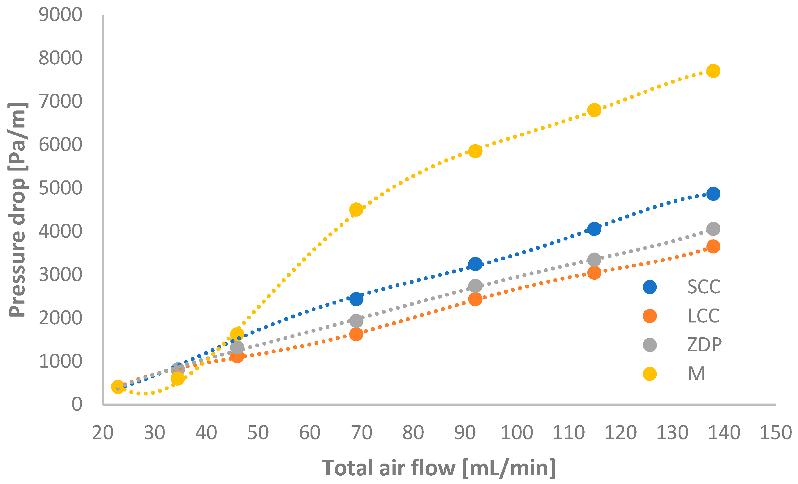
2.1.4. Measurement of Pressure Drop Through Various Monolithic Structures

In the continuation of the research, the pressure drop through the monolith produced with the FFF technique was tested. The pressure drop was measured (Figure 1) at air flow rates in the range of 23–138 mL/min (23, 34.5, 46, 69, 92, 115, and 138 mL/min), which corresponded to the flow rates used for the catalytic activity measurements that were used in the mathematical modeling. The results obtained for the 3D-printed carrier prepared by FFF (M) were compared with those obtained for the commercially available monolithic cordierite carriers with different characteristic dimensions of the square channels (i.e., 1.4 × 1.4 mm (LCC) and 1.0 × 1.0 mm (SCC)) and for the monolithic carrier fabricated by stereolithography (ZDP). The measurement results are shown in Figure 1.
As can be seen, a slightly higher pressure drop was measured for the FFF monolith (M) than for the catalyst carriers SCC, LCC, and ZDP. The pressure drop for the FFF monolith ranged from 406 to 7706 Pa/m, with a similar dependence on the volumetric air flow rate. Taking into account that the pressure drop in the chemical reactors can be more than a few hundred kPa, it can be concluded that the pressure drops in the above-mentioned 3D-printed monoliths fabricated using the FFF technique are practically negligible.
A more detailed characterization, including XRD analysis, laser diffraction analysis, an analysis of the dimensional stability of the carriers due to heat treatment, and the simultaneous DTA/TGA of the ZrO2-based filament used, was made in a previous study [35], as well as for a monolithic carrier manufactured using SLA technology [33].

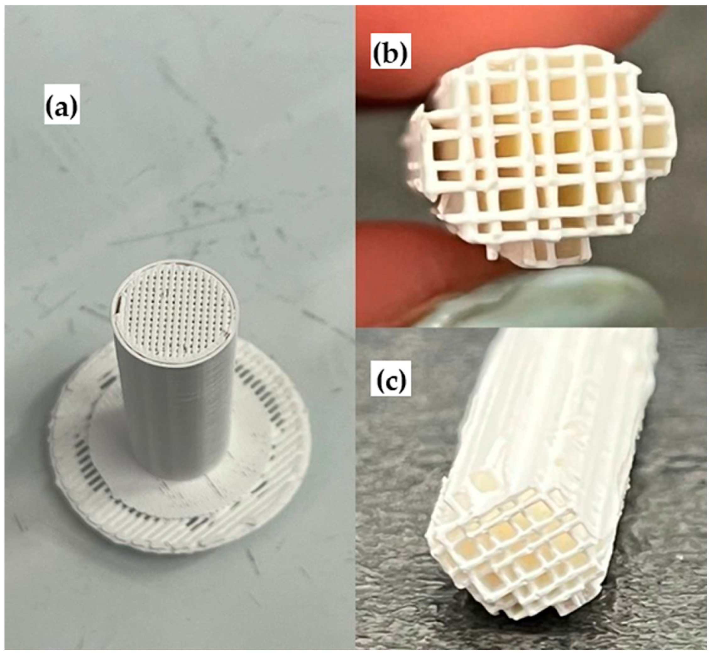
2.2. Prepared Monolithic Catalyst Carriers for Study of Catalytic Activity

With the aim of achieving finer channels, which we could not obtain from the models created in Autodesk Fusion, we decided to use a solid-cylinder model, which was then converted into a channeled cylinder in Z-SUITE software (version 2.21.0), where the infill structure effectively acted as fine channels. The optimal settings for the 3D printing, which were studied and defined in previous research [35], are listed in Table S2.
Figure 2 shows a monolith produced using FFF technology before (a) and after (b) the removal of the used support structure and excess wall material.
An overview of the monolithic carriers with their respective geometric surface areas (calculated using CAD software) and the mass of the applied catalytic layer of mixed oxides of manganese and iron (MnFeOx) is shown in Table 2.

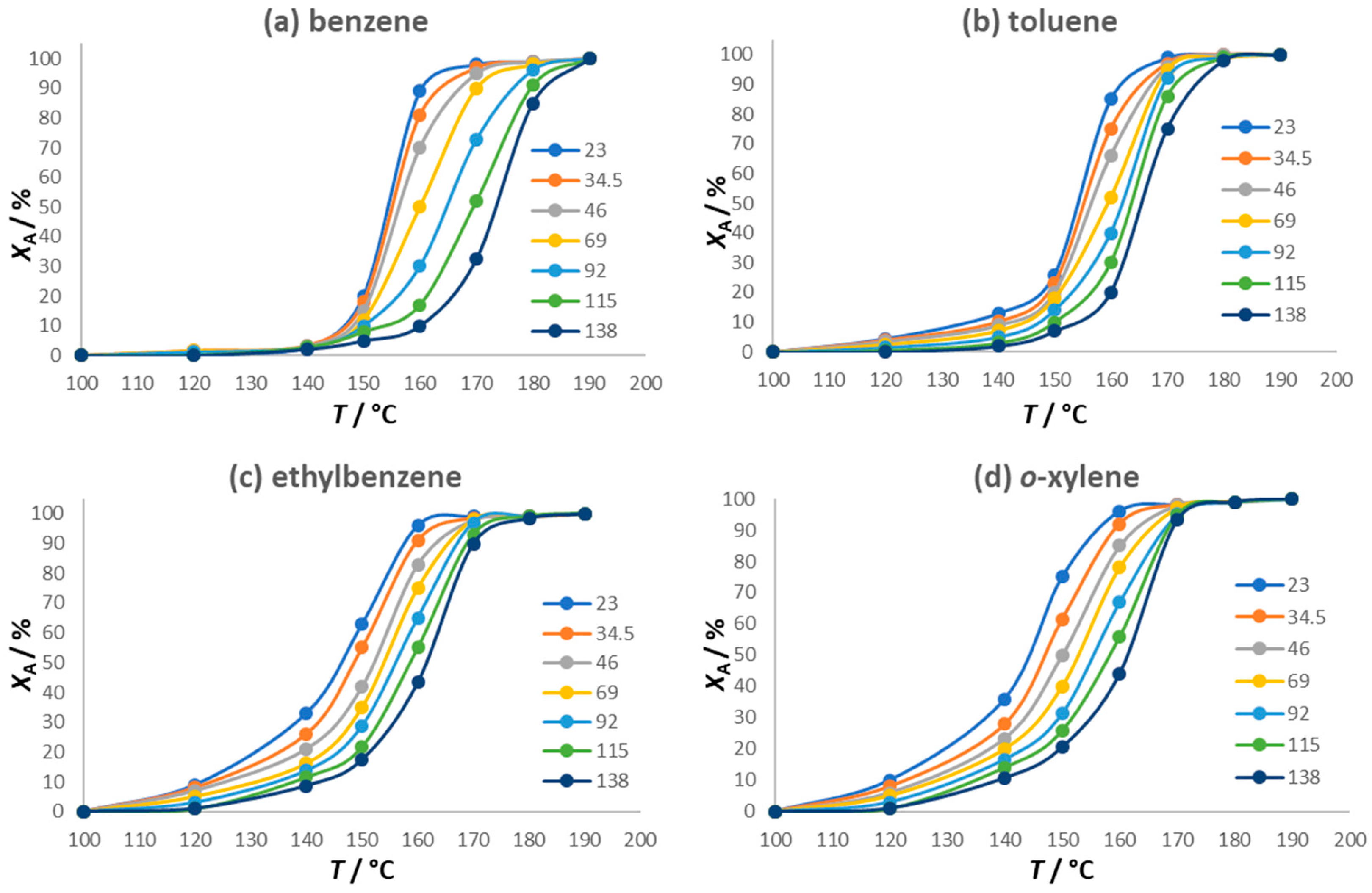
2.3. Catalytic Activity for BTEX Oxidation

The catalytic activity of the monolithic catalysts was evaluated for the oxidation of a mixture of aromatic compounds in the temperature range from 100 °C to 200 °C. The initial concentrations of the individual BTEX components in the mixture of nitrogen were 53.6 ppm for benzene, 51.3 ppm for toluene, 53.3 ppm for ethylbenzene, and 50.7 ppm for o-xylene. The catalytic measurements were carried out with a constant mass of the catalytic layer (MnFeOx), which was 50.3 mg, and with a geometric surface area of the monolith of approximately 53.4 cm2. The light-off curves, showing the conversions of benzene, toluene, ethylbenzene, and o-xylene as a function of temperature, are presented in Figure 3. The characteristic S-curves are observed, which are common for similar experimental oxidation systems. As expected, at the higher total flow rates of the reaction mixture (i.e., at lower space times), >99% conversion of the individual BTEX components was achieved at higher temperatures.

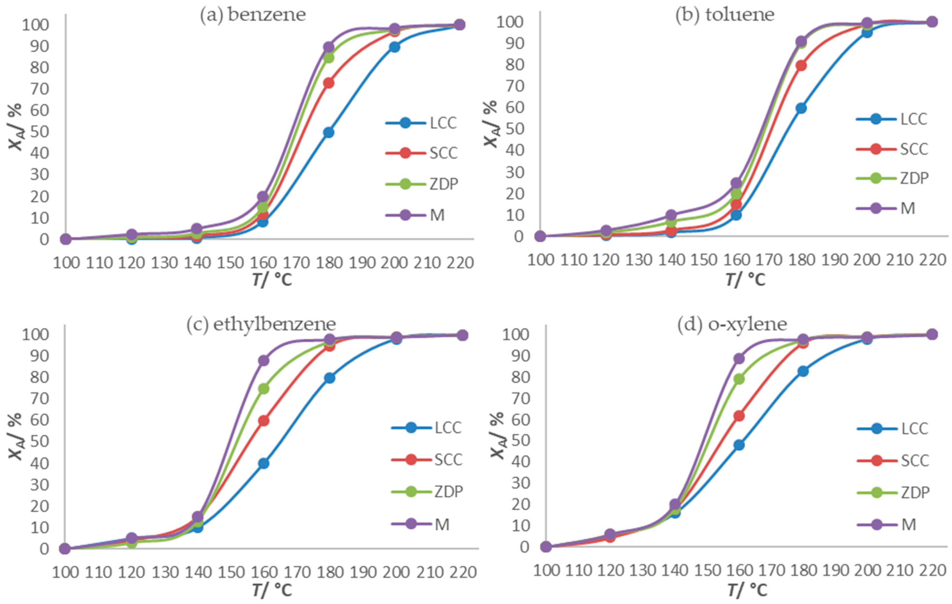
Comparison of Catalytic Activity of Monolithic Catalysts Obtained by 3D-Printing Technology with That of Commercial Cordierite

It was also found that a slightly higher operating temperature was required for a >99% conversion of benzene than that for the other components. This is evident from the results in Figure 4, which shows the dependence of the conversion of the BTEX components on the temperature over a monolithic catalyst prepared by FFF at a total flow rate of 92 mL/min. For the cordierite LCC and SCC carriers, the light-off temperatures for a 90% conversion (T90) for all BTEX components were 200 °C and 184 °C, respectively, which are slightly higher than those for the 3D-printed carriers prepared by FFF. As far as the geometric surfaces of the substrates and the mass of the catalytic layer applied to them are concerned, the results obtained are in line with expectations. The conversions of the BTEX components increased with increasing temperature, although the increase in the conversion with temperature depended on the characteristic component. It can be seen that the conversions of toluene, ethylbenzene, and o-xylene were achieved at slightly lower temperatures than that for benzene. This can be attributed to the structures of the individual compounds, which affect their conversion. The components that were converted at lower temperatures contain the corresponding substituent on the benzene ring; i.e., toluene contains one methyl group, o-xylene contains two methyl groups, and ethylbenzene contains one ethyl group. This indicates that the oxidation probably starts at the corresponding substituent and is then followed by the opening of the benzene ring. Table 3 shows the characteristic values of T10, T50, and T90, which correspond to the temperatures at which 10%, 50%, and 90% conversions were achieved for the individual BTEX components of the reaction mixture at a total flow rate of the reaction mixture and air of 92 mL/min. If a conversion of 90% (T90) at the lowest possible temperature is chosen as a criterion for the efficiency of the oxidation, it can be seen that the lowest temperature is required for the oxidation of ethylbenzene and o-xylene, followed by toluene and then benzene.
The results presented in Table 3 show that the T90 value for benzene was achieved at slightly lower temperatures for the monolith (M) produced using the FFF technique. Such results were to be expected considering that the FFF monolith has a much larger geometric surface area, which implies a larger mass of the deposited catalytic layer, as can be seen in Table 2. Therefore, a higher efficiency of the monolith produced with the FFF technique can be expected due to the complexity of the geometry, leading to a larger geometric surface area.
The achieved conversions for the pure monolithic carriers (without the catalyst layer) and the test of the stability of the catalyst (on a M geometry monolithic carrier) were reported and summarized in previous research [33,34,35].

2.4. Mathematical Modeling Results

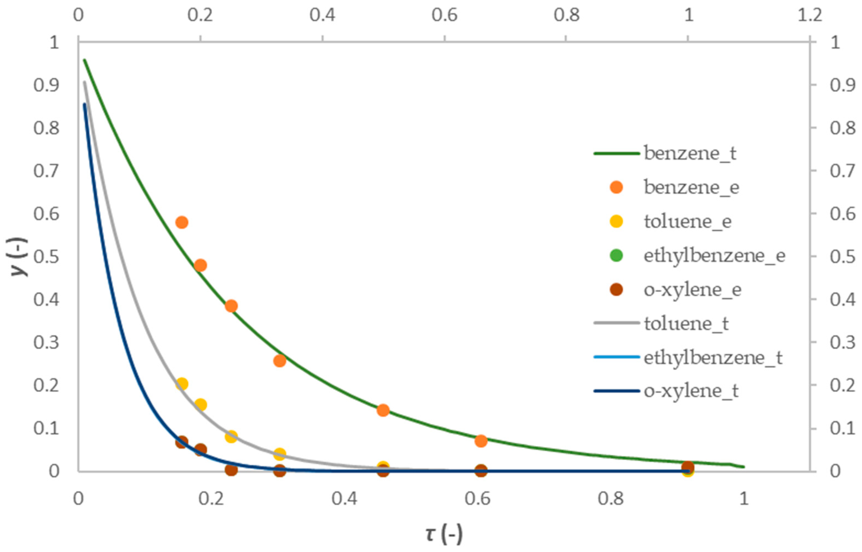
2.4.1. One-Dimensional Pseudo-Homogeneous Reactor Model

When using a one-dimensional (1D) pseudo-homogeneous model, the reactor space can be considered pseudo-homogeneous (regardless of the presence of two phases (i.e., gas phase—reaction mixture, and solid phase—catalyst), taking into account the average values of the characteristic parameters for both phases. When using such a model, the following assumptions are usually taken into account:
Steady-state operation (monolithic reactors usually operate at a steady state with a constant inflow of the reaction mixture for a given measurement cycle, while any non-stationarity is present at the beginning of operation or may occur as a result of a malfunction);
Isothermal operating conditions (due to operation with very low concentrations of the model components and with a low mass of the catalytic layer);
The ideal flow of the reaction mixture through the reactor (due to operation with relatively high flow rates);
The negligible influence of intraphase diffusion (due to a very thin catalytic layer);
A negligible pressure drop along the length of the monolithic catalyst (a common assumption for monolithic structures, experimentally confirmed by independent measurements);
The absence of catalyst deactivation;
The presence of interphase diffusion (i.e., the mass transfer of substances between the phases to the outer surface of the catalyst (a key factor when working with monolithic catalysts));
The chemical reaction takes place on the surface of the catalyst layer.
In accordance with the above assumptions, the 1D pseudo-homogeneous model is defined by the following expression for the mass balance in the fluid:
u d c A d z = f c A = r A s ρ b
where u represents the linear velocity of the gas phase, c A is the concentration in the fluid phase, r A s   is the surface reaction rate, and z is the reactor axial coordinate.
The oxidation rate on the surface of the catalytic layer is described by the kinetic model for the first-order reaction:
r A s ρ b = f c A s = k c A s
Since the reaction rate is usually defined in terms of the mass of the catalyst (mol/kg s), multiplying by the bulk density ( ρ b ) gives the reaction rate per reactor volume (Equation (1)). To solve the model equations, it is necessary to define the boundary conditions:
z = 0 ,   c A ( 0 ) = c A 0 ,   c A s 0 = c A 0
In Equation (2), k represents the reaction rate constant, which includes the Arrhenius dependence on temperature:
k = A   e E a R T
As can be seen, the balance on which the proposed model is based is represented by an ordinary differential equation that can be solved using standard numerical methods (e.g., Runge Kutta IV with the Nelder–Mead nonlinear optimization method to estimate the model parameters). The numerical solution of the model equations begins with the introduction of new dimensionless variables: the molar fraction of the compound ( y A ) and dimensionless space time ( τ ):
y A = c A c A 0 ,   τ = τ * τ m a x *
By translating the aforementioned model equation into dimensionless form, the following expressions are obtained:
The mass balance in the fluid:
d y A d τ = τ m a x * ρ b r A s
The mass balance on the catalyst surface:
r A s ρ b = k y A s
with the modified boundary conditions:
τ = 0 ,   y A 0 = 1 ,   y A s = 1
The root-mean-square deviation (SD) was used as a criterion for the agreement between the experimental results and the values obtained with the assumed model, which is defined by the following expression:
S D = 1 N 1 N ( y e y t ) 2
where y e and y t are the experimental and theoretically calculated values of a specific dependent variable ( y ), and N is the number of experimental points.
Table 4 shows the estimated values of the rate constants (k) and the corresponding values of the mean-square deviation (SD) for all four model components investigated at different temperatures. As expected, the reaction rate constants increased with increasing temperature, indicating the usual dependence of the oxidation rate of BTEX components on temperature. Considering the very small values of the SD, a satisfactory agreement of the experimental results with the theoretical values was found. The smallest oxidation rate constants at the corresponding temperature were found for benzene, followed by the other components.
Based on the Arrhenius dependence of the reaction rate constant on temperature, the corresponding values for the activation energy (Ea) and the Arrhenius number (A) were calculated, which are shown graphically in Figure 5, with the corresponding values for the Ea and A listed in Table 5.
The experimental results against the assumed 1D pseudo-homogeneous model for all four BTEX components at an operating temperature of 170 °C are shown in Figure 6, and similar results were also obtained at other temperatures (not shown here). The results obtained confirm a very good agreement between the experimental results and the proposed 1D pseudo-homogeneous model.

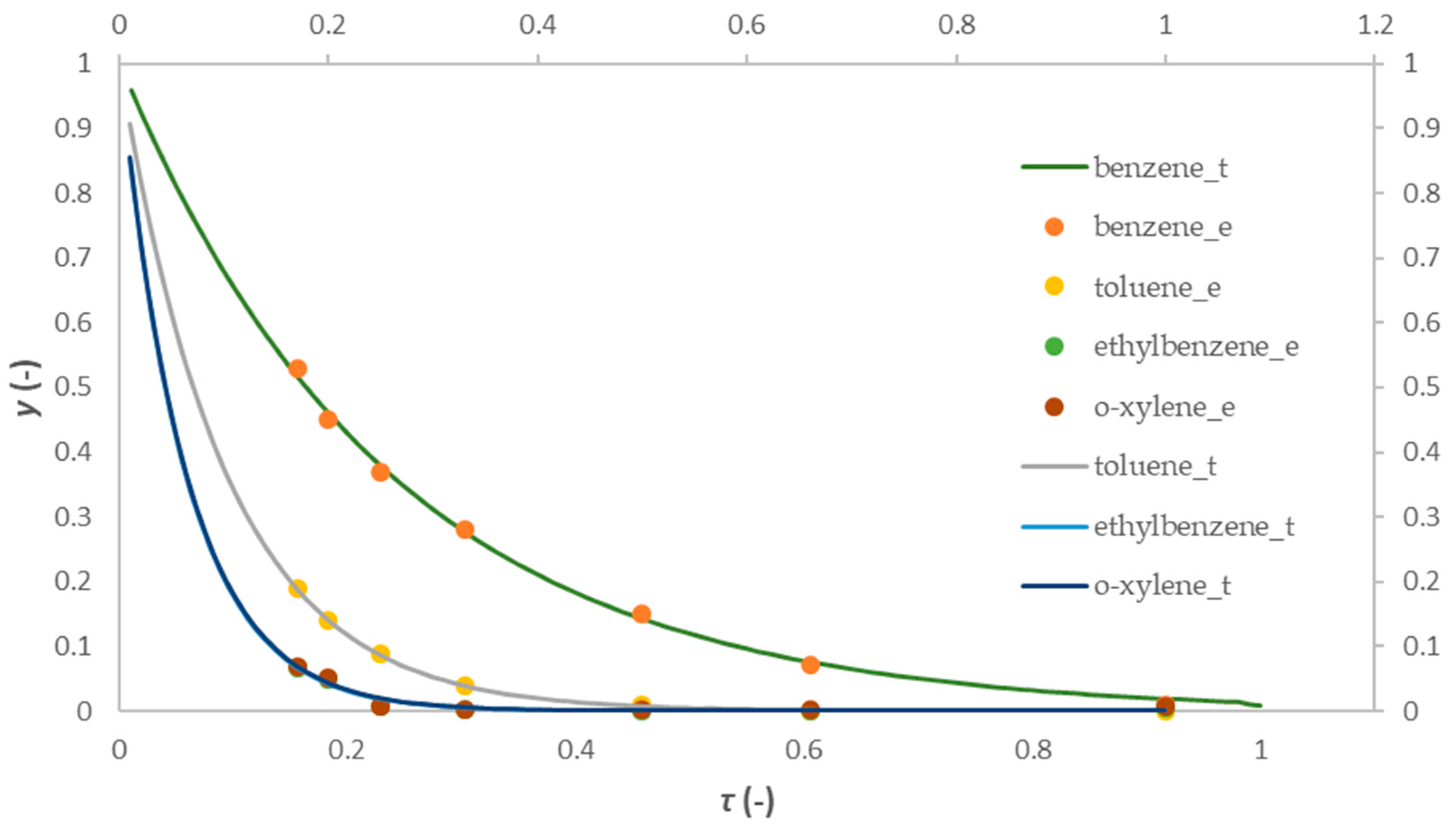
2.4.2. 1D Heterogeneous Reactor Model

A 1D heterogeneous model is used as one of the most suitable models to describe a monolithic reactor, taking into account the heterogeneity of the system. The heterogeneity of the model implies the presence of two phases: a fluid phase (reactants) and a solid phase (catalytic layer). This model is closer to the real physical picture of the process, which makes it more reliable than the pseudo-homogeneous model. Due to the assumption of the heterogeneity of the system, the corresponding mass balances have to be written separately for the fluid and solid phases because of the different concentrations of the model components in the fluid phase and on the catalyst surface. This model is one-dimensional (1D), since the concentration gradients in the radial direction within the fluid phase are neglected. Apart from this, the basic assumptions used in the derivation of this model are similar to those used in the case of the 1D pseudo-homogeneous model.
The 1D heterogeneous model is thus defined by the material balance in the gas phase and the material balance at the surface of the catalytic layer, with the definition of the boundary conditions and with the inclusion of the kinetic model:
The mass balance in the gaseous phase:
u d c A d z = k g a ( c A c A s )
The mass balance on the catalyst surface:
r s ρ b = k g a ( c A c A s )
The boundary conditions:
z = 0 ,   c A ( 0 ) = c A 0 ,   c A s 0 = c A 0
The kinetic model for the first-order reaction:
r s ρ b = k c A s
In Equations (10) and (11), k g is the intraphase mass transfer coefficient, a is the specific area per unit volume, while the meanings of the other variables are the same as those for the 1D homogeneous model.
The numerical solution begins with the introduction of appropriate substitutions, as in the case of the 1D pseudo-homogeneous model:
y A = c A c A 0 ,   τ = τ * τ m a x *
The balance for the model component in the gas phase:
d y A d τ = k g a τ m a x * ( y A y A s )
The balance for the model component on the catalyst surface:
r s ρ b = k g a ( y A y A s )
The boundary conditions at the reactor inlet:
z = 0 ,   y A 0 = 1 ,   y A s 0 = 1
The reactor model contains the kinetic model already mentioned, Equation (11). As with the pseudo-homogeneous 1D model, the root-mean-square deviation (SD), defined by Equation (8), was used as a criterion for the agreement between the experimental results and the values obtained with the assumed model. The interphase mass transfer coefficient (kg) was calculated using an empirical correlation that is appropriate for the observed system (i.e., a correlation based on dimensionless features linking the flow properties, fluid properties, and system geometry); i.e., Sh = f(Re, Sc) (according to the Hawthorn correlation), taking into account that kg also changes with spatial time (i.e., with a change in the volume flow rate).
In contrast to the 1D pseudo-homogeneous model, this model takes into account the influence of the external diffusion (interphase mass transfer) on the overall oxidation rate at the surface of the heterogeneous catalyst. The results shown in Table 6 indicate that the reaction rate constants (k) increased continuously in the temperature range from 130 to 190 °C, regardless of the component under consideration.
The interphase mass transfer coefficient (kg) mainly increased with increasing temperature from 130 °C to 160 °C (benzene) or up to a temperature of 170 °C (o-xylene), while it mainly decreased at higher temperatures. These results arose from the fact that the kg increases more slowly with increasing temperature than the reaction rate constant (k) and becomes the limiting step that determines the overall reaction rate when the oxidation reaction is carried out at higher temperatures (>160 °C). The differences in the characteristic temperature dependencies of the kg for the investigated BTEX components can also be attributed to different oxidation mechanisms, which come into play in particular when the oxidation is carried out in a wider temperature range. Based on the Arrhenius dependence of the reaction rate constants on the temperatures, the corresponding values for the activation energy (Ea) and the Arrhenius number (A) were calculated, which are shown graphically in Figure 7, and the corresponding values for the Ea and A are listed in Table 7.
A comparison of the results shown in Table 5 and Table 7 shows that the 1D heterogeneous model provided slightly higher values for the activation energies of the BTEX components investigated than those of the 1D pseudo-homogeneous model.
A comparison of the experimental results with the assumed 1D heterogeneous model for all four BTEX components at an operating temperature of 170 °C is shown in Figure 8. The results obtained confirm that a good agreement between the experimental results and the proposed 1D heterogeneous model was obtained, which is consistent with the results presented in Table 7.

3. Materials and Methods

3.1. Chemicals and Materials

Zirconium dioxide (ZrO2)-based filament (Zetamix) was used as a material for the production of ceramic monolithic catalyst carriers using the FFF technique. Manganese(II) nitrate tetrahydrate (Mn(NO3)2 × 4H2O) and iron(III) nitrate nonahydrate (Fe(NO3)3 × 9H2O), supplied by Fisher Scientific, were used as the precursors for the preparation of the catalytically active compounds. Acetone (C3H6O) and ethanol (C2H6O) were provided by Gram Mol. A gas mixture of benzene (C6H6), toluene (C6H5CH3), ethylbenzene (C6H5CH2CH3), and o-xylene (C6H4(CH3)2) in nitrogen (50 ppm of each component in nitrogen) was provided by Messer, and synthetic air of research purity was supplied by the SOL Group.

3.2. Preparation of Ceramic Monolithic Catalyst Carriers

3.2.1. FFF Technology

The ZrO2-based monolithic catalyst carriers were fabricated using an M200 3D-printer (Zortrax, Olsztyn, Poland). Before the 3D printing, it was necessary to design 3D models of the catalyst carriers (Figures S2 and S3). For this purpose, Autodesk Fusion software (version v.2.0.19941) was used to create the models, while Z-SUITE software (version 2.21.0) was used as the so-called slicer to define the 3D-printing parameters and add the support structure, which enables the structural stability of the models during the production process. This includes the ability to choose the shape and density of the model’s internal structure (infill), the layer thickness, the extrusion temperature, changes in the dimensions along any of the spatial axes (scale factors), the fan speed (used for the cooling of the freshly extruded material layer), and similar settings. The optimal 3D printing settings were determined in previous research [35].
After the post-treatment of the carrier, the next step was to remove the polymer phase. This process is called debinding, and the first step is simply immersing the monolith in acetone for 2 h (chemical debinding). The next step is the thermal treatment of the monolith, which is carried out in a laboratory furnace according to the instructions provided by the manufacturer (thermal debinding) [39]. After the debinding process, the ceramic phase must be sintered in order to obtain a mechanically stable catalyst carrier. Sintering is carried out in a high-temperature furnace for 2h at 1475 °C using a heating rate of 50 °C/h.

3.2.2. SLA Technology

SLA ceramic monolithic catalyst carriers were produced using a Form 2 3D-printer (Formlabs, Somerville, MA, USA). The material used to produce the carriers was the Ceramic Resin from the same manufacturer. The 3D CAD models of the monolithic carriers were created using the same software as that used for the carriers prepared using FFF technology, Autodesk Fusion.
Once the model has been 3D-printed, it must be carefully separated from the building platform. The support structure is mechanically removed by cutting and sanding with sandpaper of varying fineness to remove the remains of the connecting parts of the support structure and the models themselves (touchpoints). In the next phase, the prepared carriers are placed in a high-temperature furnace and heat-treated according to a procedure specified by the manufacturer [40]. The optimal 3D-printing settings and the manufacturing process were studied in our previous research [33].

3.2.3. Commercial Cordierite

The cordierite catalyst carriers were obtained by cutting segments of commercially available inert cordierite carriers with a CSI (cells per square inch) of 300 for the LCC geometry and of 400 for the SCC geometry (Figure S4). The dimensions of the commercial monolithic carriers were chosen so that their lengths corresponded to the dimensions of other manufactured monolithic carriers, while the diameter was defined based on the diameter of the reactor into which the monolithic catalyst was inserted during catalytic oxidation. The length of the cut cordierite segments was 40 mm, with a diameter of 7 mm. After cutting the segments to the desired dimensions, the cordierite carriers were washed in ethanol (96%) and then dried for 30 min at 120 °C in a laboratory oven. Catalyst carriers produced in this way are ready for the application of catalytically active components.

3.3. Characterization of Polymer–ZrO2 Composite Filament

3.3.1. Moisture Resistance Test

The moisture resistance test of the ZrO2 filament was carried out to check whether water absorption from the air occurs over time. The test was performed by exposing approximately 5 g of filament samples to room conditions and comparing their mass with the initial mass of the filament at several time periods (up to 72 h).

3.3.2. Determination of Content of Ceramic Phase in ZrO2-Based Filament

The ceramic phase content in the ZrO2-based filament was determined using the heat treatment in a laboratory furnace. Approximately 5 g of the filament samples (that were previously used for the moisture resistance test) were post-treated as described in Section 3.2.1. After heat treatment, the samples were weighed, and their mass was compared to the mass before treatment.

3.3.3. FTIR Analysis

FTIR was used for the characterization of the polymer phase of the ZrO2 filament. The analysis was performed using a Spectrum One (PerkinElmer) FTIR spectrometer in attenuated total reflectance mode. Absorbance data was collected in the range of 600–4000 cm−1.

3.3.4. Pressure Drop Measurements

Pressure drop measurements were conducted using a piezoelectric pressure sensor PX126 (OMEGA Engineering, Norwalk, CT, USA). The measured values were normalized using the reactor with quartz infill (rod) and quartz wool, without a catalyst carrier, as a reference. This pressure sensor works on the principle of differential pressure measurement (i.e., the pressure difference between two points in the system). To perform the measurement, the sensor was connected to the catalytic oxidation system so that it measured the pressure difference between the inlet and outlet of the reactor. A universal digital meter EX330 (Extech Instruments, Nashua, NH, USA) was connected to the sensor so that the voltage could be read in mV. The measured voltage was converted into a pressure in Pa according to the sensor manufacturer’s instructions.
The measurement used an air flow rate equal to the overall flow rate that was used during the catalytic activity measurements. Therefore, the pressure drop was tested by passing 23, 34.5, 46, 69, 92, 115, and 138 mL/min of air.

3.4. Coating of 3D-Printed Carriers with Catalytically Active Components

The 3D-printed ceramic monolithic carriers were coated using wet impregnation. The impregnation solution of catalytic precursors needs to be prepared by dissolving the catalytic precursors (Mn(NO3)2 × 4H2O) and Fe(NO3)3 × 9H2O) in deionized water. We prepared 1M solutions of the individual precursors and then mixed them in the same molar ratio: Mn:Fe = 1:1. The carriers were immersed in the precursor solution for 15 min and subsequently dried in a laboratory oven at 100 °C for 30 min to evaporate excess water, reducing the risk of potential damage to the carrier and catalytic layer during the calcination process. After drying, calcination was performed in a laboratory furnace for 2 h at 500 °C, using a heating rate of 2.5 °C/min. During calcination, the catalytic precursors formed mixed oxides of manganese and iron, which were catalytically active.

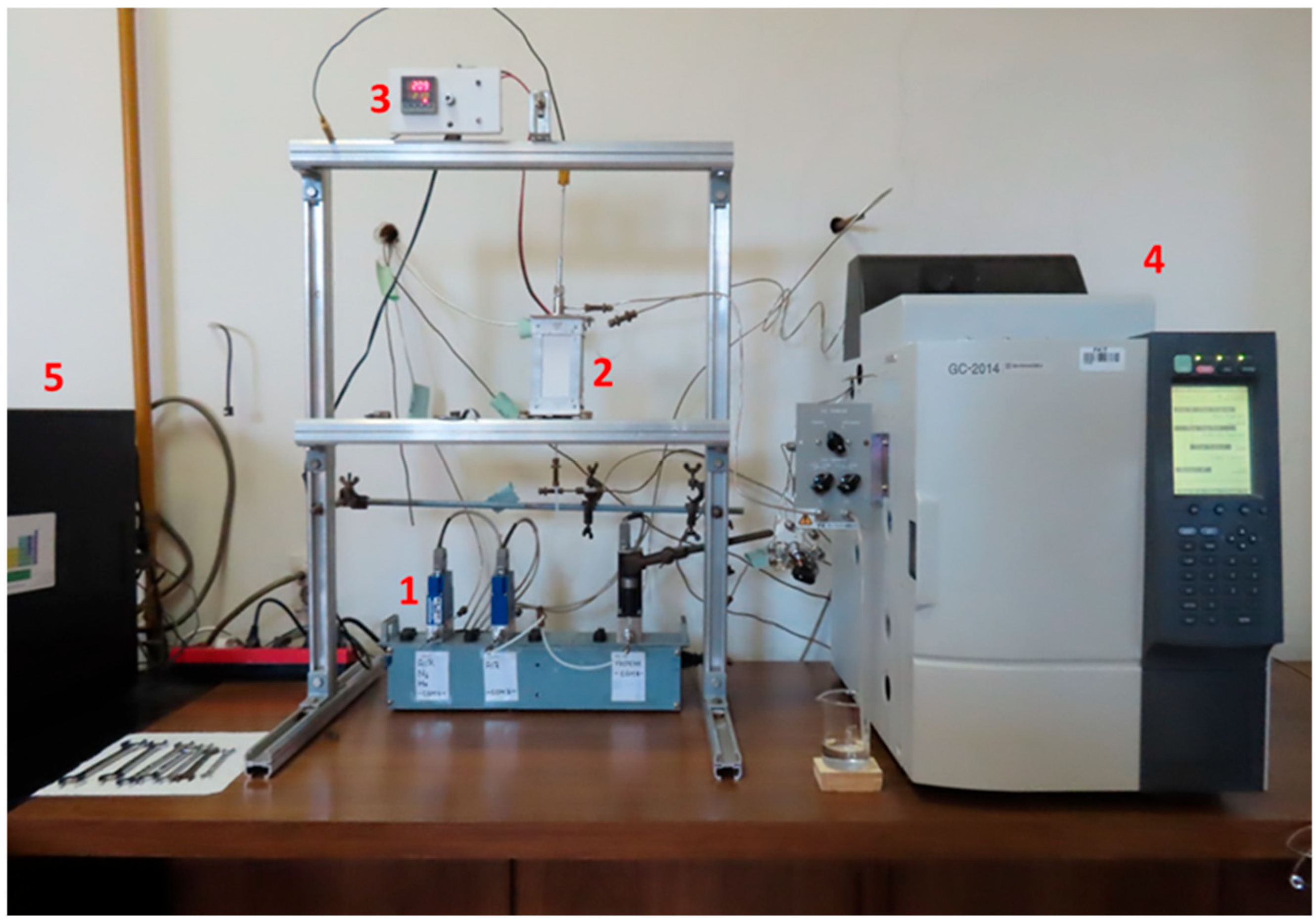
3.5. Evaluation of Catalytic Performance

The catalytic oxidation of BTEX compounds was conducted in a monolithic reactor. The reaction was monitored by using on-line gas chromatography, with a GC-2014 (Shimadzu, Zagreb, Croatia) gas chromatograph with a flame ionization detector (FID). The oxidation reactions were carried out at atmospheric pressure over a temperature range from room temperature to 200 °C and at different space times. The space times were varied by changing the total flow rate of the reaction mixture (BTEX compounds) and synthetic air at a constant volume ratio (6.67) of the reactants and oxidant (synthetic air). The gas flow rates were regulated by Brooks (Amsterdam, The Netherlands) mass flow controllers (MFCs). The reactor was placed in the heating block with a thermocouple connected to a TC208 series thermo-controller (Winpark, Shandong, China). The set-up of the experimental system is shown in Figure 9, while the set-up of the monolithic reactor is shown in the Supplementary Materials (Figure S5).

3.6. Mathematical Modeling

For the mathematical description of the experimental system, suitable reactor models were proposed in the last part of this work, ranging from a simpler 1D pseudo-homogeneous model to a somewhat more complex 1D heterogeneous reactor model. In both cases, a kinetic model for a first-order reaction was used to describe the reaction rate, as is common in the analysis of such systems, especially when no data on other oxidation products are available. The fact that both models are one-dimensional indicates that the characteristic state variables are functions of a single independent variable, namely, the length of the reactor, and that the properties of the gas phase are the same depending on the cross section of the reactor. It is known that one-dimensional models can describe the adiabatic or isothermal mode of the reactor operation, which was the case in this work. The experiments were carried out at different temperatures, and the concentrations of the model components at the reactor outlet were measured at different inlet flow rates of the reaction mixture. The modeling was performed for the monolithic catalyst produced using FFF (M geometry with MnFeOx), as it showed the highest catalytic activity.

4. Conclusions

The aims of this work were to fabricate a ceramic monolithic catalyst using fused filament fabrication (FFF) and to test the activity of the fabricated monolithic catalyst for the catalytic oxidation of BTEX. The main objective of this work was to test the catalytic activity of a new design of monoliths, produced using FFF, which is a relatively robust technology compared to SLA, and to define kinetic and reactor models, including the assessment of the acceptability of the proposed models. The approach demonstrated in this work, using the infill to significantly increase the geometric surface area, makes FFF a competitive technology for the fabrication of monolithic catalysts that can be used for the catalytic oxidation of VOCs. The results obtained were compared with those obtained under the same operating conditions using ceramic cordierite monolithic catalysts with different channel dimensions and a monolithic catalyst fabricated by stereolithography (SLA). In the last part of the work, two reactor models with the corresponding kinetic model were proposed to describe the catalytic oxidation of BTEX compounds.
The results of the FTIR analysis showed that the ZrO2 filament probably contained EVA as the polymer phase. Based on the determination of the proportion of the polymer and ceramic phase, it was found that the material was homogeneous, and that a mass reduction of 14% occurred during the heat treatment of the filament.
The results of the experimental determination of the pressure drop showed that the pressure drop was relatively low; i.e., it ranged from 400 to 7700 Pa/m.
The comparison of the results of the catalytic oxidation of a mixture of BTEX compounds on monolithic catalysts produced using the SLA process and FFF process and monolithic cordierite catalysts with different channel dimensions showed that 3D printing can not only compete with commercially available ceramics in terms of the conversions achieved, but also that the results are even better than those achieved with monolithic catalyst carriers made of commercially available cordierite ceramics.
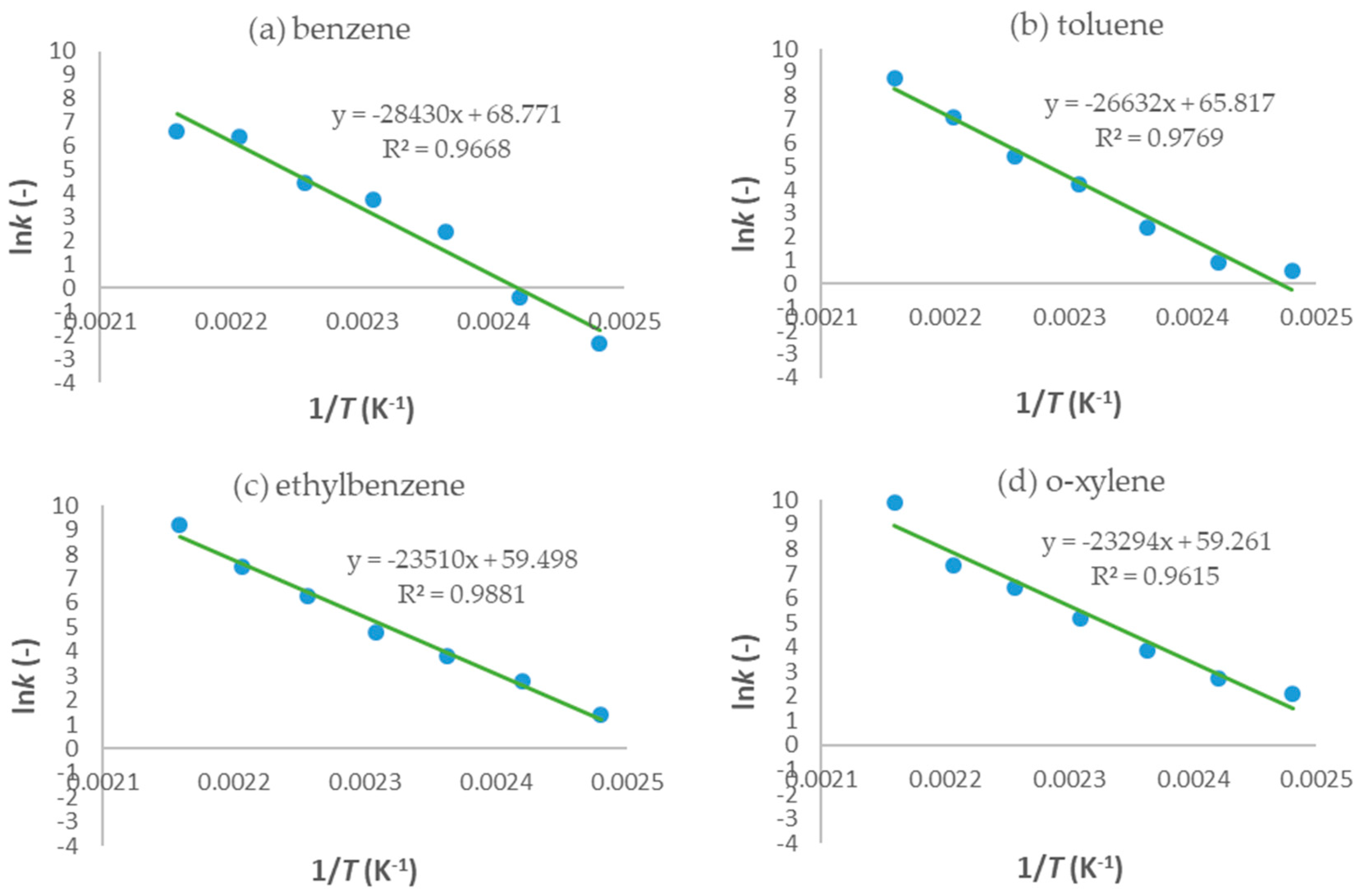
In the last part of the research, 1D pseudo-homogeneous and 1D heterogeneous reactor models were derived, which included a kinetic model for the first-order reaction, and were used to describe the oxidation of a mixture of BTEX compounds in a monolithic reactor prepared by the FFF technique. An assessment of the acceptability of the proposed models was carried out. The values of the key parameters of the proposed models were estimated based on a comparison of the experimental results with the theoretical values obtained according to the proposed models. Based on the corresponding mean-square deviation (SD) values, it was found that the proposed models described the experimental results well. Compared to the 1D pseudo-homogeneous model, the 1D heterogeneous model provides a more realistic description of the studied system and allows conclusions to be drawn about the influence of interphase diffusion on the overall oxidation rate on a heterogeneous catalyst.

Supplementary Materials

The following supporting information can be downloaded at https://www.mdpi.com/article/10.3390/catal15070677/s1, Figure S1: FTIR spectrum of the ZrO2 filament sample; Figure S2: Three-dimensional CAD model of the catalyst carrier—M geometry; Figure S3: Three-dimensional CAD model of the catalyst carrier—ZDP geometry; Figure S4: Cordierite catalyst carriers—LCC (left) and SCC (right) geometries; Figure S5: Scheme of the monolithic reactor. Table S1. Results of the moisture resistance test. Table S2. 3D-printing settings used for production of M catalyst carrier geometry [35].

Author Contributions

Conceptualization, F.C., D.V., and V.T.; methodology, F.C. and V.T.; validation, F.C., V.T., and Z.G.; formal analysis, F.C. and D.H.; investigation, F.C. and D.H.; resources, V.T.; data curation, F.C., D.H., and Z.G.; writing—original draft preparation, F.C., D.H., and V.T.; writing—review and editing, F.C., D.V., and V.T.; visualization, F.C. and V.T.; supervision, V.T.; project administration, F.C. and V.T.; funding acquisition, V.T. All authors have read and agreed to the published version of the manuscript.

Funding

This research was supported by the Croatian Science Foundation under the project IP-2022-10-8004.

Data Availability Statement

The original contributions presented in this study are included in the article. Further inquiries can be directed to the corresponding author.

Conflicts of Interest

The authors declare no conflicts of interest.

References

  1. Słomińska, M.; Król, S.; Namieśnik, J. Removal of BTEX Compounds from Waste Gases; Destruction and Recovery Techniques. Crit. Rev. Environ. Sci. Technol. 2013, 43, 1417–1445. [Google Scholar] [CrossRef]
  2. Shojaei, A.; Ghafourian, H.; Yadegarian, L.; Lari, K.; Sadatipour, M.T. Removal of volatile organic compounds (VOCs) from waste air stream using ozone assisted zinc oxide (ZnO) nanoparticles coated on zeolite. J. Environ. Health Sci. Eng. 2021, 19, 771–780. [Google Scholar] [CrossRef] [PubMed]
  3. Song, S.; Zhang, S.; Zhang, X.; Verma, P.; Wen, M. Advances in Catalytic Oxidation of Volatile Organic Compounds over Pd-Supported Catalysts: Recent Trends and Challenges. Front. Mater. 2020, 7, 595667. [Google Scholar] [CrossRef]
  4. Liang, C.; Li, C.; Zhu, Y.; Du, X.; Yao, C.; Ma, Y.; Zhao, J. Recent advances of photocatalytic degradation for BTEX: Materials, operation, and mechanism. Chem. Eng. J. 2023, 455, 140461. [Google Scholar] [CrossRef]
  5. Bian, Y.; Zhang, Y.; Zhou, Y.; Feng, X. BTEX in the environment: An update on sources, fate, distribution, pretreatment, analysis, and removal techniques. Chem. Eng. J. 2022, 435, 134825. [Google Scholar] [CrossRef]
  6. Berenjian, A.; Chan, N.; Malmiri, H.J. Volatile organic compounds removal methods: A review. Am. J. Biochem. Biotechnol. 2012, 8, 220–229. [Google Scholar] [CrossRef]
  7. Su, F.; Lu, C.; Johnston, K.R.; Hu, S. Kinetics, Thermodynamics, and Regeneration of BTEX Adsorption in Aqueous Solutions via NaOCl-Oxidized Carbon Nanotubes. In Environanotechnology; Elsevier: Amsterdam, The Netherlands, 2010; pp. 71–97. [Google Scholar] [CrossRef]
  8. Kim, H.S.; Kim, H.J.; Kim, J.H.; Kim, J.H.; Kang, S.H.; Ryu, J.H.; Park, N.K.; Yun, D.S.; Bae, J.W. Noble-Metal-Based Catalytic Oxidation Technology Trends for Volatile Organic Compound (VOC) Removal. Catalysts 2022, 12, 63. [Google Scholar] [CrossRef]
  9. Kamal, M.S.; Razzak, S.A.; Hossain, M.M. Catalytic oxidation of volatile organic compounds (VOCs)—A review. Atmos. Environ. 2016, 140, 117–134. [Google Scholar] [CrossRef]
  10. Shakeri, H.; Arshadi, M.; Salvacion, J.W.L. Removal of BTEX by using a surfactant—Bio originated composite. J. Colloid Interface Sci. 2016, 466, 186–197. [Google Scholar] [CrossRef]
  11. Tomatis, M.; Xu, H.H.; He, J.; Zhang, X.D. Recent Development of Catalysts for Removal of Volatile Organic Compounds in Flue Gas by Combustion: A Review. J. Chem. 2016, 15, 8324826. [Google Scholar] [CrossRef]
  12. Lou, B.; Shakoor, N.; Adeel, M.; Zhang, P.; Huang, L.; Zhao, Y.; Zhao, W.; Jiang, Y.; Rui, Y. Catalytic oxidation of volatile organic compounds by non-noble metal catalyst: Current advancement and future prospectives. J. Clean. Prod. 2022, 363, 132523. [Google Scholar] [CrossRef]
  13. De los Santos, C.; Vidal, H.; Gatica, J.M.; Yeste, M.P.; Cifredo, G.; Castiglioni, J. Optimized preparation of washcoated clay honeycomb monoliths as support of manganese catalysts for acetone total combustion. Microporous Mesoporous Mater. 2021, 310, 110651. [Google Scholar] [CrossRef]
  14. Lu, T.; Su, F.; Zhao, Q.; Li, J.; Zhang, C.; Zhang, R.; Liu, P. Catalytic oxidation of volatile organic compounds over manganese-based oxide catalysts: Performance, deactivation and future opportunities. Sep. Purif. Technol. 2022, 296, 121436. [Google Scholar] [CrossRef]
  15. Moulijn, J.A.; Kreutzer, M.T.; Nijhuis, T.A.; Kapteijn, F. Monolithic Catalysts and Reactors: High Precision with Low Energy Consumption. Chem. React. Eng. 2011, 54, 249–327. [Google Scholar] [CrossRef]
  16. Govender, S.; Friedrich, H.B. Monoliths: A Review of the Basics, Preparation Methods and Their Relevance to Oxidation. Catalysts 2017, 7, 62. [Google Scholar] [CrossRef]
  17. Hosseini, S.; Moghaddas, H.; Soltani, S.M.; Kheawhom, S. Technological Applications of Honeycomb Monoliths Prepared via Extrusion and Coating of Structured Supports in Environmental Processes: A Review. Process Saf. Environ. Prot. 2019, 133, 286–300. [Google Scholar] [CrossRef]
  18. Alimi, O.A.; Akinnawo, C.A.; Meijboom, R. Monolith catalyst design by 3D printing: A reusable support for modern palladium-catalyzed cross-coupling reactions. New J. Chem. 2020, 44, 18867–18878. [Google Scholar] [CrossRef]
  19. Tang, L.; Zhao, Z.; Li, K.; Yu, X.; Wei, Y.; Liu, J.; Peng, Y.; Li, Y.; Chen, Y. Highly Active Monolith Catalysts of LaKCoO3 Perovskite-type Complex Oxide on Alumina-washcoated Diesel Particulate Filter and the Catalytic Performances for the Combustion of Soot. Catal. Today 2020, 339, 159–173. [Google Scholar] [CrossRef]
  20. Santos, D.F.M.; Soares, O.S.G.P.; Figueiredo, J.L.; Sanz, O.; Montes, M.; Pereira, M.F.R. Preparation of ceramic and metallic monoliths coated with cryptomelane as catalysts for VOC abatement. Chem. Eng. J. 2019, 382, 122923. [Google Scholar] [CrossRef]
  21. Aguero, F.N.; Morales, M.R.; Duran, F.G.; Barbero, B.P.; Cadus, L.E. MnCu/Cordierite Monolith used for Catalytic Combustion of Volatile Organic Compounds. Chem. Eng. Technol. 2013, 36, 1749–1754. [Google Scholar] [CrossRef]
  22. Chen, L.; Zhou, S.; Li, M.; Mo, F.; Yu, S.; Wei, J. Catalytic Materials by 3D Printing: A Mini Review. Catalysts 2022, 12, 1081. [Google Scholar] [CrossRef]
  23. Lawson, S.; Li, X.; Thakkar, H.; Rownaghi, A.A.; Rezai, F. Recent Advances in 3D Printing of Structured Materials for Adsorption and Catalysis Applications. Chem. Rev. 2021, 121, 6246–6291. [Google Scholar] [CrossRef] [PubMed]
  24. Parra-Cabrera, C.; Achille, C.; Kuhn, S.; Ameloot, R. 3D printing in chemical engineering and catalytic technology: Structured catalysts, mixers and reactors. Chem. Soc. Rev. 2018, 47, 209–230. [Google Scholar] [CrossRef]
  25. Guan, Z.; Yang, X.; Liu, P.; Xu, X.; Li, Y.; Yang, X. Additive manufacturing of zirconia ceramic by fused filament fabrication. Ceram. Int. 2023, 49, 27742–27749. [Google Scholar] [CrossRef]
  26. Nötzel, D.; Eickhoff, R.; Pfeifer, C.; Hanemann, T. Printing of Zirconia Parts via Fused Filament Fabrication. Materials 2021, 14, 5467. [Google Scholar] [CrossRef]
  27. Bogdan, E.; Michorczyk, P. 3D Printing in Heterogeneous Catalysis—The State of the Art. Materials 2020, 13, 4534. [Google Scholar] [CrossRef]
  28. Zhu, J.; Wu, P.; Chao, Y.; Yu, J.; Zhu, W.; Liu, Z.; Xu, C. Recent advances in 3D printing for catalytic applications. Chem. Eng. J. 2022, 433, 134341. [Google Scholar] [CrossRef]
  29. He, Q.; Jiang, J.; Yang, X.; Zhang, L.; Zhou, Z.; Zhong, Y.; Shen, Z. Additive manufacturing of dense zirconia ceramics by fused deposition modeling via screw extrusion. J. Eur. Ceram. Soc. 2021, 41, 1033–1040. [Google Scholar] [CrossRef]
  30. Cano, S.; Gonzalez-Gutierrez, J.; Sapkota, J.; Spoerk, M.; Arbeiter, F.; Schuschnigg, S.; Holzer, C.; Kukla, C. Additive manufacturing of zirconia parts by fused filament fabrication and solvent debinding: Selection of binder formulation. Addit. Manuf. 2019, 26, 117–128. [Google Scholar] [CrossRef]
  31. Cano, S.; Lube, T.; Huber, P.; Gallego, A.; Naranjo, J.A.; Berges, C.; Schuschnigg, S.; Herranz, G.; Kukla, C.; Holzer, C.; et al. Influence of the Infill Orientation on the Properties of Zirconia Parts Produced by Fused Filament Fabrication. Materials 2020, 13, 3158. [Google Scholar] [CrossRef]
  32. Hadian, A.; Koch, L.; Koberg, P.; Sarraf, F.; Liersch, A.; Sebastian, T.; Clemens, F. Material extrusion based additive manufacturing of large zirconia structures using filaments with ethylene vinyl acetate based binder composition. Addit. Manuf. 2021, 47, 102227. [Google Scholar] [CrossRef]
  33. Car, F.; Brnadić, G.; Vrsaljko, D.; Tomašić, V. Advanced preparation method of monolithic catalyst carriers using 3D-printing technology. Prog. Addit. Manuf. 2022, 7, 797–808. [Google Scholar] [CrossRef]
  34. Car, F.; Sušec, I.; Tomašić, V. Preparation and testing of cordierite monolithic catalysts for oxidation of aromatic volatile organic compounds. Chem. Eng. Trans. 2021, 86, 673–678. [Google Scholar] [CrossRef]
  35. Car, F.; Zekić, N.; Vrsaljko, D.; Tomašić, V. Innovative Production of 3D-Printed Ceramic Monolithic Catalysts for Oxidation of VOCs by Using Fused Filament Fabrication. Catalysts 2025, 15, 125. [Google Scholar] [CrossRef]
  36. D’Amelia, R.P.; Gentile, S.; Nirode, W.F.; Huang, L. Quantitative Analysis of Copolymers and Blends of Polyvinyl Acetate (PVAc) Using Fourier Transform Infrared Spectroscopy (FTIR) and Elemental Analysis (EA). World J. Chem. Educ. 2016, 4, 25–31. [Google Scholar]
  37. Jiang, Z.; Hu, C.; Easa, S.M.; Zheng, X.; Zhang, Y. Evaluation of physical, rheological, and structural properties of vulcanized EVA/SBS modified bitumen. J. Appl. Polym. Sci. 2017, 134, 44850. [Google Scholar] [CrossRef]
  38. Barretta, C.; Oreski, G.; Kyranaki, N.; Mansour, D.E.; Betts, T.R.; Bauermann, L.P.; Resch-Fauster, K. Effects of artificial ageing tests on EVA degradation: Influence of microclimate and methodology approach. In Proceedings of the IEEE 48th Photovoltaic Specialists Conference (PVSC), Fort Lauderdale, FL, USA, 20–25 June 2021. [Google Scholar] [CrossRef]
  39. Available online: https://zetamix.fr/en/produit/white-zirconia-filament/ (accessed on 4 June 2023).
  40. Available online: https://formlabs.com/materials/ceramics/ (accessed on 18 March 2023).
Figure 1. Comparison of the pressure drops for different monolithic catalyst carrier geometries.
Catalysts 15 00677 g001
Figure 2. The monolithic catalyst carrier before mechanical processing (a) and after mechanical processing (b) and (c).
Catalysts 15 00677 g002
Figure 3. Influence of the total flow rate of the reaction mixture and temperature on the conversion of (a) benzene, (b) toluene, (c) ethylbenzene, and (d) o-xylene for the 3D-printed monolithic catalyst carrier prepared by FFF (M geometry) with MnFeOx as a catalytic layer. The numbers in the legend in Figure 3 indicate that the oxidation of BTEX was carried out at a total flow rate of the reaction mixture of 23 to 138 mL/min.
Catalysts 15 00677 g003
Figure 4. Influence of temperature on the conversions of BTEX compounds over prepared monolithic catalysts at a total flow of reactants and air of 92 mL/min.
Catalysts 15 00677 g004
Figure 5. Determination of the activation energy (Ea) and Arrhenius number (A) of benzene for a 1D pseudo-homogeneous model.
Catalysts 15 00677 g005
Figure 6. Experimental results (points) on a 1D pseudo-homogeneous model (lines) at 170 °C for a monolithic catalyst fabricated by the FFF technique with MnFeOx as the catalytic layer.
Catalysts 15 00677 g006
Figure 7. Determination of the activation energy (Ea) and Arrhenius number (A) of benzene for a 1D heterogeneous model.
Catalysts 15 00677 g007
Figure 8. Experimental results for a 1D heterogeneous model at 170 °C.
Catalysts 15 00677 g008
Figure 9. Set-up of the experimental system. 1. Mass flow controllers (MFCs) for the regulation of the flow of reactants (BTEX and synthetic air); 2. A monolithic reactor placed inside a heater unit; 3. A temperature control unit (TCU) for the regulation of the temperature in the reactor, which is connected to the reactor with a thermocouple; 4. A gas chromatograph (GC) for the on-line data acquisition; 5. A PC unit for data analysis.
Catalysts 15 00677 g009
Table 1. Mass loss during the heat treatment.
SampleMass Before Heat Treatment (g)Mass After Heat Treatment (g)Mass Loss (%)
A5.00344.299414.07
B4.99414.287914.14
C4.99894.293114.12
Table 2. Overview of the monolithic catalyst carrier used in this study.
Monolithic Catalyst Carrier/Fabrication MethodGeometric Surface Area (cm2)Mass of the Catalytic
Layer (mg)
Loading of Catalyst Per Gram of Carrier (mg/g)
M/FFF53.450.322.2
ZDP/SLA28.033.47.1
SCC/Extrusion29.06.99.0
LCC/Extrusion21.06.411.2
Table 3. Corresponding temperatures at which 10%, 50%, and 90% conversions of the individual BTEX components were achieved over prepared monolithic catalysts at a total flow rate of the reaction mixture and air of 92 mL/min.
Monolithic Catalyst CarrierBenzeneTolueneEthylbenzeneo-xylene
T10T50T90T10T50T90T10T50T90T10T50T90
SCC162171184157169179124157172122154172
LCC163179200161170184126165180135164176
ZDP161170179151168177122155170121150170
M156166176149159168120154165120148162
Table 4. Results of testing on a 1D pseudo-homogeneous model—estimated values of rate constants (k) and root-mean-square deviations (SDs) for a monolithic catalyst fabricated by the FFF technique with MnFeOx as the catalytic layer.
T/°CBenzeneTolueneEthylbenzeneo-Xylene
k (min−1)SD∙103k (min−1)SD∙103k (min−1)SD∙103k (min−1)SD∙103
1300.021.160.052.960.124.720.136.68
1400.054.260.167.730.466.560.5012.13
1500.066.000.3011.081.2611.981.2616.62
1601.9563.383.3567.465.7034.775.7133.78
1704.2348.609.8311.6815.862.3015.712.45
18013.734.1429.720.0638.390.1971.640.39
19023.570.61193.702.17 × 10−5165.161.69 × 10−497.821.57 × 10−5
Table 5. Activation energy (Ea), and Arrhenius number (A) values for individual BTEX components on a monolithic MnFeOx catalyst for a 1D pseudo-homogeneous model.
BTEX ComponentEa (kJ/mol)A (min−1)
Benzene229.967.24 × 1027
Toluene205.081.33 × 1025
Ethylbenzene182.595.34 × 1022
o-xylene179.362.24 × 1022
Table 6. Results of testing on a 1D heterogeneous model—estimated values of rate constants (k) and root-mean-square deviations (SDs) for a monolithic catalyst fabricated by the FFF technique with MnFeOx as the catalytic layer.
T/°CBenzeneTolueneEthylbenzeneo-Xylene
k (min−1)kg (cm/min)SD∙103k (min−1)kg (cm/min)SD∙103k (min−1)kg (cm/min)SD∙103k (min−1)kg (cm/min)SD∙103
1300.302.731.160.724.412.961.992.494.721.972.276.68
1400.702.284.252.562.667.727.942.146.559.731.2912.19
1500.962.046.004.822.1111.0923.283.8311.9723.743.7116.62
16042.3338.3763.3867.8622.9567.48121.0130.1634.78118.8827.8733.78
17087.2729.5348.61232.0522.6211.67550.3177.812.30631.4088.922.52
180611.2899.484.141218.8030.540.061739.3230.440.071520.4433.490.08
190736.6033.270.598493.3678.115.02 × 10−311,759.6589.633.24 × 10−519,643.2387.281.26 × 10−5
Table 7. Activation energy (Ea) and Arrhenius number (A) values for individual BTEX components on a monolithic MnFeOx catalyst for a 1D pseudo-homogeneous model.
BTEX ComponentEa (kJ/mol)A (min−1)
Benzene236.377.36 × 1029
Toluene221.423.84 × 1028
Ethylbenzene195.466.91 × 1025
o-Xylene193.675.45 × 1025
Disclaimer/Publisher’s Note: The statements, opinions and data contained in all publications are solely those of the individual author(s) and contributor(s) and not of MDPI and/or the editor(s). MDPI and/or the editor(s) disclaim responsibility for any injury to people or property resulting from any ideas, methods, instructions or products referred to in the content.

