Article

Revolutionizing Hydrogen Production: Unveiling the Role of Liquid Metals in Methane Pyrolysis over Iron Catalysts Supported on Titanium Dioxide and Alumina

by
Hamid Ahmed
1,
Amal BaQais
2,
Fekri Abdulraqeb Ahmed Ali
3,
Ahmed I. Osman
4,
Anis H. Fakeeha
1,
Ahmed E. Abasaeed
1,
Ahmed A. Ibrahim
1,*,
Syed Farooq Adil
5,
Tahani Saad Algarni
5 and
Ahmed S. Al-Fatesh
1
1
Chemical Engineering Department, College of Engineering, King Saud University, P.O. Box 800, Riyadh 11421, Saudi Arabia
2
Department of Chemistry, College of Science, Princess Nourah bint Abdulrahman University, P.O. Box 84428, Riyadh 11671, Saudi Arabia
3
Chemical Engineering Department, College of Engineering, Imam Mohammad Ibn Saud Islamic University (IMSIU), Riyadh 11432, Saudi Arabia
4
School of Engineering, Technology, and Design, Canterbury Christ Church University, Canterbury CT1 1QU, UK
5
Department of Chemistry, College of Science, King Saud University, Riyadh 11451, Saudi Arabia
*
Author to whom correspondence should be addressed.
Catalysts 2025, 15(7), 631; https://doi.org/10.3390/catal15070631
Submission received: 14 May 2025 / Revised: 19 June 2025 / Accepted: 24 June 2025 / Published: 27 June 2025

Abstract

Catalytic methane decomposition offers an attractive and sustainable pathway for producing COx-free hydrogen and valuable carbon nanotubes. This work investigates the innovative use of liquid metals, particularly gallium and indium, as promoters for iron catalysts based on a titanium dioxide and alumina composite to improve this process even more. In a fixed-bed reactor operating at 800 °C and atmospheric pressure, all catalyst activities for methane decomposition were thoroughly assessed while keeping the gas hourly space velocity at 6 L/g h. Surface area and porosity, H2-temperature programmed reduction/oxidation, X-ray diffraction, Raman spectroscopy, scanning transmission electron microscopy, and thermogravimetry analysis were utilized to investigate the physicochemical properties of the catalyst. The result showed that iron supported on a titanium-alumina catalyst exhibited higher activity, stability, and reproducibility with a methane conversion of 90% and hydrogen production of 81% after three cycles, with 240 min for each cycle and stability for 480 min. In contrast, the liquid metal-promoted catalysts improved the metal-support interaction and textural properties, such as surface area, pore volume, and particle dispersion of the catalysts. Still, the catalytic efficiency significantly improved. However, the gallium-promoted catalyst displayed excellent reusability. The characterization of the spent catalyst proved that both the iron supported on a titanium-alumina and its gallium-promoted derivative produced graphitic carbon; on the contrary, the indium-promoted catalyst produced amorphous carbon. These results demonstrate how liquid metal promoters can be used to adjust the characteristics of catalysts, providing opportunities for improved reusability and regulated production of carbon byproducts during methane decomposition.

1. Introduction

As the global economy grows rapidly, the widespread reliance on conventional energy sources like fossil fuels has consistently resulted in significant environmental pollution and harm to ecosystems [1,2]. Hydrogen, the most abundant element on Earth, is widely regarded as a promising source of energy that will soon be utilized, using its easily produced and environmentally friendly combustion byproduct [3,4]. Furthermore, the global consumption rate of hydrogen is rising by approximately 3–4% annually [5], highlighting the urgent need for stable and efficient methods of producing hydrogen with minimal environmental consequences. Hydrogen is commonly produced through complex processes, including steam reforming and partial oxidation of natural gas. These methods result in the creation of syngas as an initial step, followed by the water gas shift reaction and subsequent separation and purification processes. Nevertheless, these processes are energy-intensive and contribute significantly to global warming through the production of large amounts of CO2 [6,7,8]; therefore, the thermocatalytic decomposition of methane (CMD) is considered an appealing technique for generating high-quality hydrogen. This is because breaking down CH4 leads to the creation of hydrogen without any COx byproducts, along with the formation of premium carbon nanotubes [9,10].
Heat energy is needed to generate the reaction in CMD, which is an endothermic process. However, achieving complete decomposition at temperatures above 1000 °C can be challenging. Therefore, thermos-catalytic methane decomposition with the right catalyst becomes essential as it enables the reaction to proceed at lower temperatures [11,12]. CMD has been the focus of extensive research, with many studies exploring transition metal and noble metal-based catalysts. Among these, catalysts based on cobalt (Co) [13], nickel (Ni) [14], iron (Fe) [15], and palladium (Pd) [16] have demonstrated potential, showcasing improved activity and stability for CMD. Nickel and cobalt-based catalysts, in particular, display high activity for CMD and remain the most extensively studied catalysts in this area [17]. Recently, Fe-based catalysts for the CMD process have gained much attention [18,19,20,21]. Iron-based catalysts possess unique qualities that position them as a preferred option for the CMD process in commercial applications. This preference stems from Fe catalysts being more cost-effective and environmentally friendly than Co and Ni catalysts [22,23,24]. Additionally, Fe catalysts offer the advantage of operating within a temperature range of 700 °C to 950 °C [25]. The higher operating temperature range with Fe catalysts can improve thermodynamic methane decomposition rates [26].
Support materials play a crucial role in catalyst design, influencing the dispersion and stability of metal particles and ultimately affecting carbon yield and methane conversion efficiency. By impacting the metal particles’ electronic properties, size, and surface chemistry, the support material significantly affects catalytic performance. Therefore, careful selection of support is important for optimizing the activity and stability of Fe-based catalysts because they play a significant part in the catalytic reaction by increasing the metal catalyst dispersion, which enhances catalyst activity while reducing catalyst sintering [27]. Iron dispersed over silica was found to be inactive towards CH4 decomposition, whereas Fe dispersed over alumina was quite active at 70% initial H2-yield at 800 °C [28,29]. However, the hindrance of active sites by inert carbon limits the application of Ni/Al2O3 further.
In the same way, encapsulation of the active site by carbon is a major drawback found when the lanthanum-supported Fe catalyst was employed [30]. When ceria support was used for the iron catalyst in the CH4 decomposition reaction, COx contamination was found, which could be owing to the oxidation of deposited carbon by lattice oxygen of ceria [31]. Using dual metal oxide as support for Fe catalyst, it was found to overcome the limitations of Fe over individual metal oxides, such as the 20 wt% silica/80% alumina as support for Fe catalyst was found to attain 76% initial H2 yield and 80% H2 yield up to 330 min time on stream [28]. Moreover, the presence of TiO2 can enhance the reducibility and oxygen mobility, but the phase transition of titania at high temperatures is a major limitation in using it as support for Fe-based catalyst [32]. However, adding titanium dioxide to γ-Al2O3, a support with a comparatively large surface area and the capacity to transmit oxygen, can be created at the same time, and the catalysts’ composition and characteristics can be further improved [33].
On the other hand, the use of LMs like gallium and indium to enhance catalytic performance has become a popular area of research. The liquid phase in catalysis aims to leverage the unique properties of these metals to improve conversion rates without facing the issues of coking and coarsening that are often seen when using solid catalysts in similar applications [34,35]. LMs possess desirable characteristics that make them attractive choices as promoters in the catalysts. These include low viscosities, strong thermal and electrical conductivities, and the capacity to remain liquid over a wide temperature range because of their comparatively low melting and somewhat higher boiling temperatures [36,37]. Earlier, Ga addition was found to increase the reducibility of Ni or Co over different supports like mesoporous silicates, zirconia-alumina, and lantana-zirconia [38]. The reduction profile of gallium-doped iron oxide catalysts was shifted to a higher temperature, indicating a stronger interaction between gallium oxide and Iron oxide [38]. Gallium oxide is also reducible, and partially reduced Ga3+ was reported to form an alloy with metallic Fe at 500–600 °C, which may stabilize the metallic state of Fe (active sites) further [27,38].
Moreover, the indium support catalyzed the dehydrogenation of hydrocarbons (like propane) in the presence of an oxidant, CO2 [27]. LMs have become potentially valuable promoter catalysts in the process of methane pyrolysis for hydrogen production because they make it easier to remove solid carbon deposits, which can block catalytic sites and decrease the lifespan of the catalyst [39,40]. Recent research suggests that the liquid metal-based catalyst might not exhibit the strong catalytic activity initially sustained as anticipated. It seems to work more as a heat-transfer medium instead, and it is interesting to note that the solid carbon product may play a part in the catalytic breakdown of methane [36]. Incorporating additional metals through alloying presents a promising strategy to boost the catalytic performance of liquid metal-based catalysts significantly, which offers a pathway to optimize and enhance the efficiency of the catalysts, potentially leading to more effective and sustainable processes in methane pyrolysis.
In continuation of our previous work [41], we herein study the impact of the liquid metals (gallium and indium) as the promoter on our previously reported catalyst active metal (iron) supported on titania and alumina, which is synthesized by the hydrothermal method and evaluated for methane decomposition for the first time. Moreover, several techniques were used to characterize the produced catalysts to examine their crystalline, structural, and reducibility characteristics. The as-prepared catalysts are assessed specifically for their methane conversion and hydrogen yields. The study also examined how the regeneration and long-term stability of the catalyst influence methane conversion and hydrogen yield. Additionally, the nanocarbon deposited on the catalysts is collected, and X-ray diffraction, TEM, and Raman spectroscopy were used to thoroughly characterize the catalysts’ structural, crystalline, and morphological properties.

2. Results and Discussion

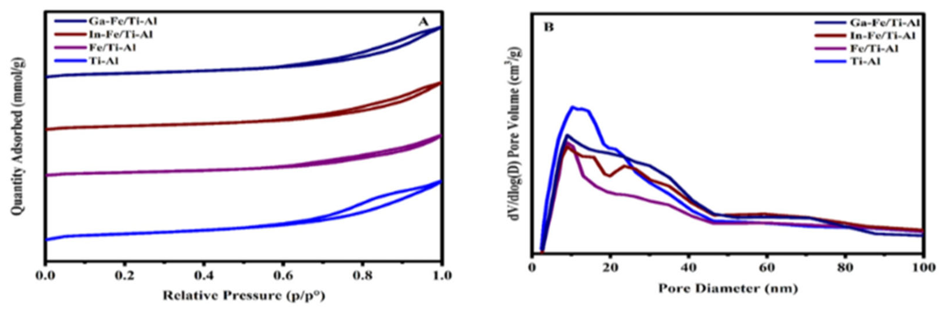
2.1. Structure Analysis
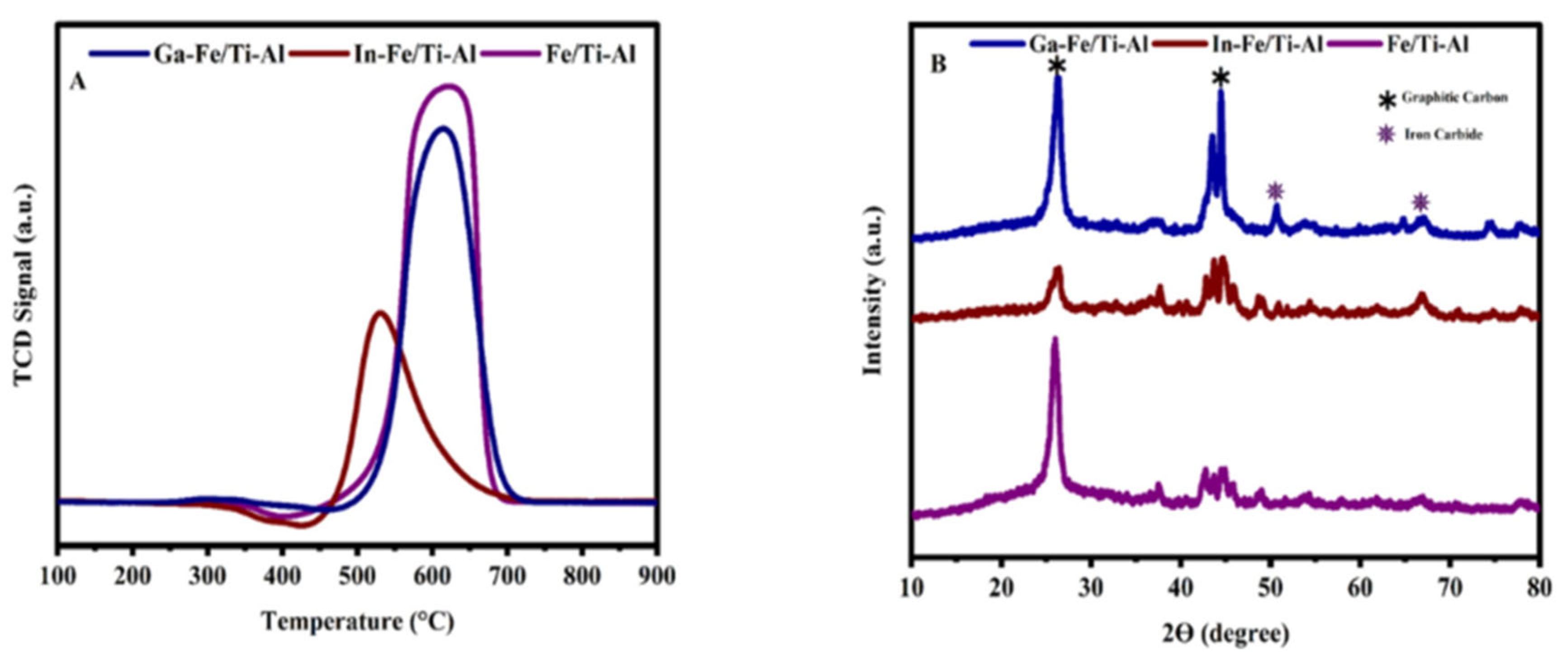
The textural characteristics of the support and fresh mixed oxide catalysts were examined using N2 adsorption–desorption tests, as depicted in Figure 1A. As per the IUPAC classification, all the isotherms in Figure 1 exhibit characteristics of type IV, which are typical of mesoporous materials. The hysteresis loop is observed in H1 and H3, indicating the presence of slit-shaped or cylindrical mesopores [42]. Table 1 shows that the surface area of the synthesized support 20Ti-Al decreased significantly with the addition of different amounts of iron due to the physical blocking or filling of pores within the 20Ti-Al support; the surface area of the 20Ti-Al support is 239 m2/g with pore volume 0.68 cm3/g and pore size 10.04 nm. However, after loading the iron, the surface area decreased to 143 m2/g with a pore volume of 0.46 cm3/g and a pore size of 10.10 nm. These reductions in surface area observed in the Fe/Ti-Al catalyst could be explained by the metal species’ obstruction of mesopores.
In addition, after promoting the catalyst with indium and gallium, the surface area, pore volume, and average pore size were improved for both catalysts. This is attributed to the enhanced dispersion of active sites upon the addition of promoters. The surface areas of the In-Fe/Ti-Al and Ga-Fe/Ti-Al are 164 m2/g and 174 m2/g, respectively. These observations can be explained by the enhanced dispersion of active sites upon the addition of promoters. Figure 1B’s BJH pore size distribution curves verify that all of the catalysts under study have pores that are at least 40 nm in diameter. Figure 1B makes it abundantly evident that pores larger than 20 nm are also present in all samples, reaching up to and maybe beyond 40 nm, even though pores less than 20 nm are the most common and account for the largest portion of the total pore volume.

2.2. Reducibility

The redox characteristics of the catalysts were investigated through reducibility analysis, revealing distinct reduction profiles as illustrated in Figure 2. In iron-based catalysts, the reduction peaks at approximately 400 °C, 550 °C, and 700 °C are ascribed to the consecutive reduction of iron oxides as Fe2O3 → Fe3O4 → FeO → Fe. The Fe/Ti-Al catalyst showed an intense peak at approximately 400 °C and diffuse peaks at high temperatures [43]. The three catalysts exhibited varied reduction patterns both with and without the presence of a promoter. Double reduction peaks were identified in the cases of the Ga-Fe/Ti-Al catalysts. A weak reduction peak was observed within the temperature range of 300–412 °C, followed by a strong reduction peak between 600–750 °C. The reduction peak at low temperatures is associated with converting bulk hematite species to magnetite (α-Fe2O3-Fe3O4).
On the other hand, the high-temperature reduction peaks are generally linked to the robust metal-support interaction, primarily involving the reduction of FeO to metallic Fe. The gallium oxide reduction peak was also reported at 390 °C [44]. Since Ga2O3 is a promoter in this system, its low concentration indicates that it makes a negligible contribution to the reduction profile as a whole. The decrease profile for In-Fe/Ti-Al displayed three different temperature areas and a large peak. The catalyst’s surface hematite is reduced to magnetite, which is responsible for the first peaks. The reduction of both magnetite to metallic iron and In2O3 is likely indicated by a broad peak centered at approximately 550 °C [45].
Finally, the strong reduction peak at 720 °C is associated with reducing FeO to zero-valent metallic Fe species. With the addition of indium or gallium as promoters over Fe/Ti-Al, the intensity of the last peak was significant. It indicates the presence of a higher density of active sites (metallic iron) on promoted catalysts. Interestingly, the high-temperature peak is relatively shifted to a lower temperature over the Ga-Fe/Ti-Al catalyst than the In-Fe/Ti-Al catalyst, which indicates that upon Ga’s promotional addition over Fe/Ti-Al, the edge of reducibility also grows. This results in a high density of active sites being prepared at a relatively lower temperature over the Ga-Fe/Ti-Al catalyst than the In-Fe/Ti-Al catalyst. This enhancement is evidenced by the higher hydrogen consumption observed in the promoter catalyst compared to the non-promoter catalyst, as detailed in Table 1. This suggests that in these two catalysts, more iron oxide was reduced to iron due to the presence of the promoters.

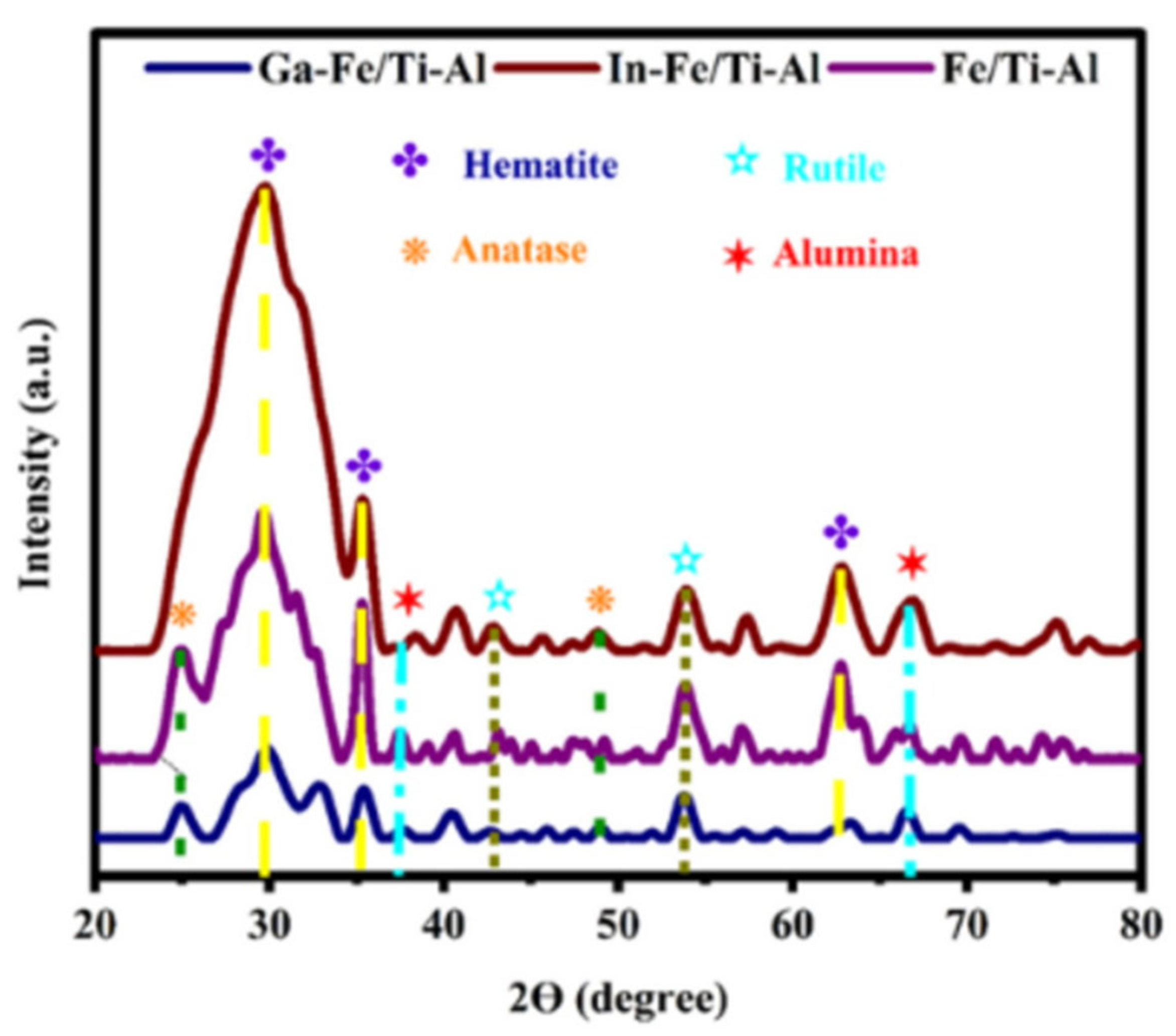
2.3. X-Ray Diffraction

The data from the X-ray diffraction analysis are presented in Figure 3. The interpretation of data was done using the X’Pert database. The characteristic peaks for the Anatase TiO2 phase at the Bragg’s angle (2θ) 25°, and 48.8°,(JCPDS: 021-1272) [46] and the Rutile phase at the Bragg’s angle (2θ) 44°, and 54° (JCPDS: 021-1276) [46] and the alumina phase at the Bragg’s angle (2θ) 37.8°, and 66.7° (JCPDS: 00-029-0063). In addition, iron and liquid metal promoters approved that the diffraction peak-related phase (hematite phase) was intensified at Bragg’s angle (2θ) 30°, 35.5°, 54°, and 62.4° (JCPDS: 00- 025-1402) [45]. In Ga-Fe/Ti-Al, the characteristic peaks for the hematite phase are also depleted, whereas in the In-Fe/Ti-Al catalyst, this phase is highly intense. It indicates that Ga induces superior iron dispersion over the Ga-Fe/Ti-Al catalyst, and indium induces the least iron dispersion over the In-Fe/Ti-Al catalyst.

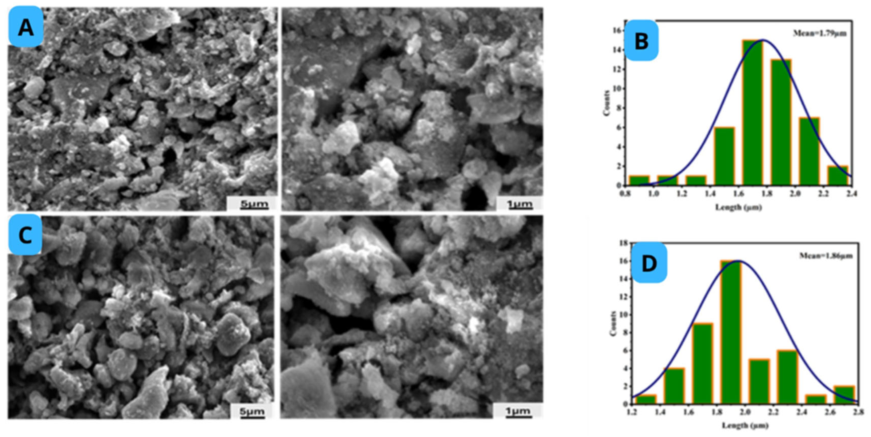
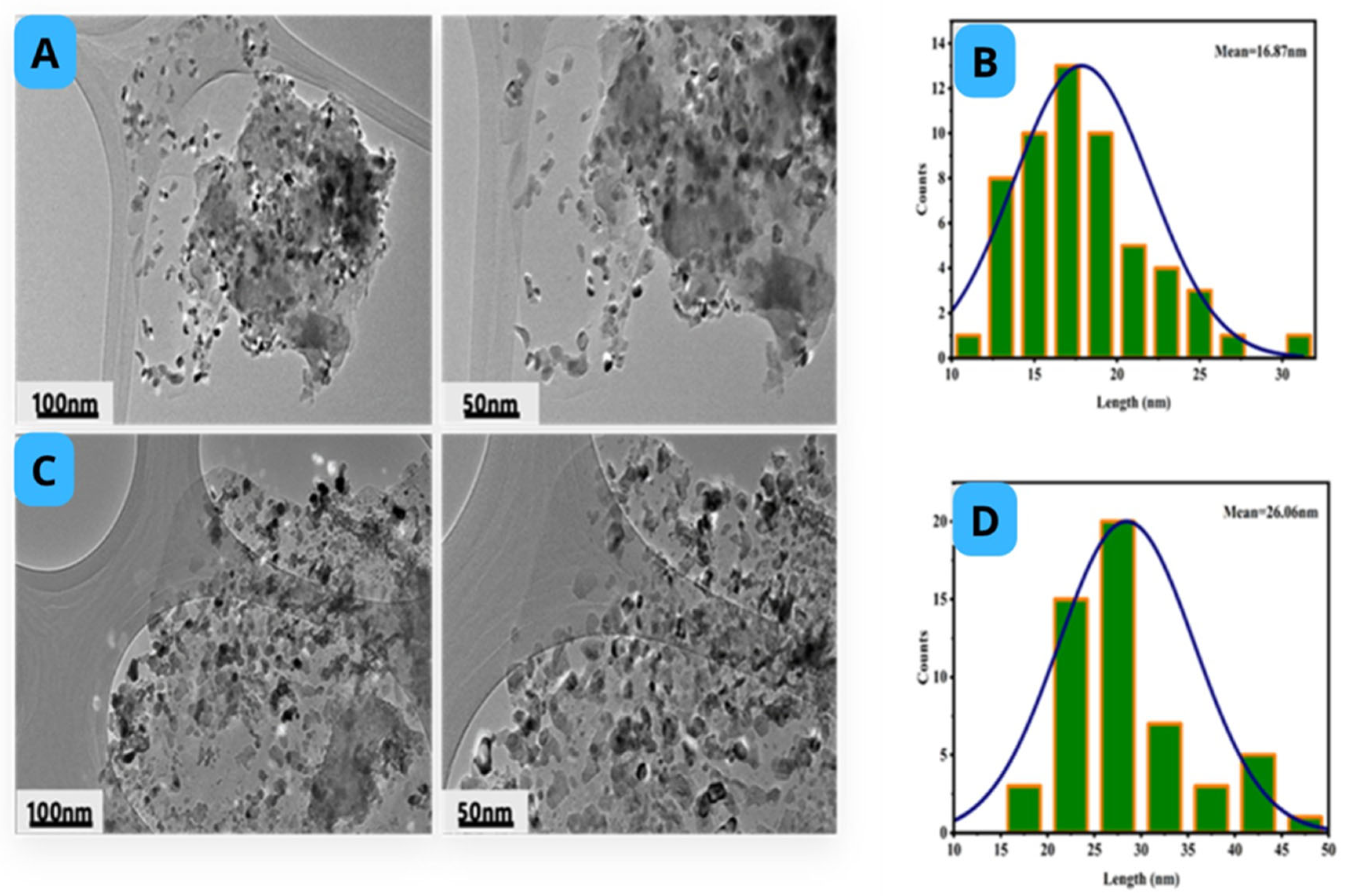
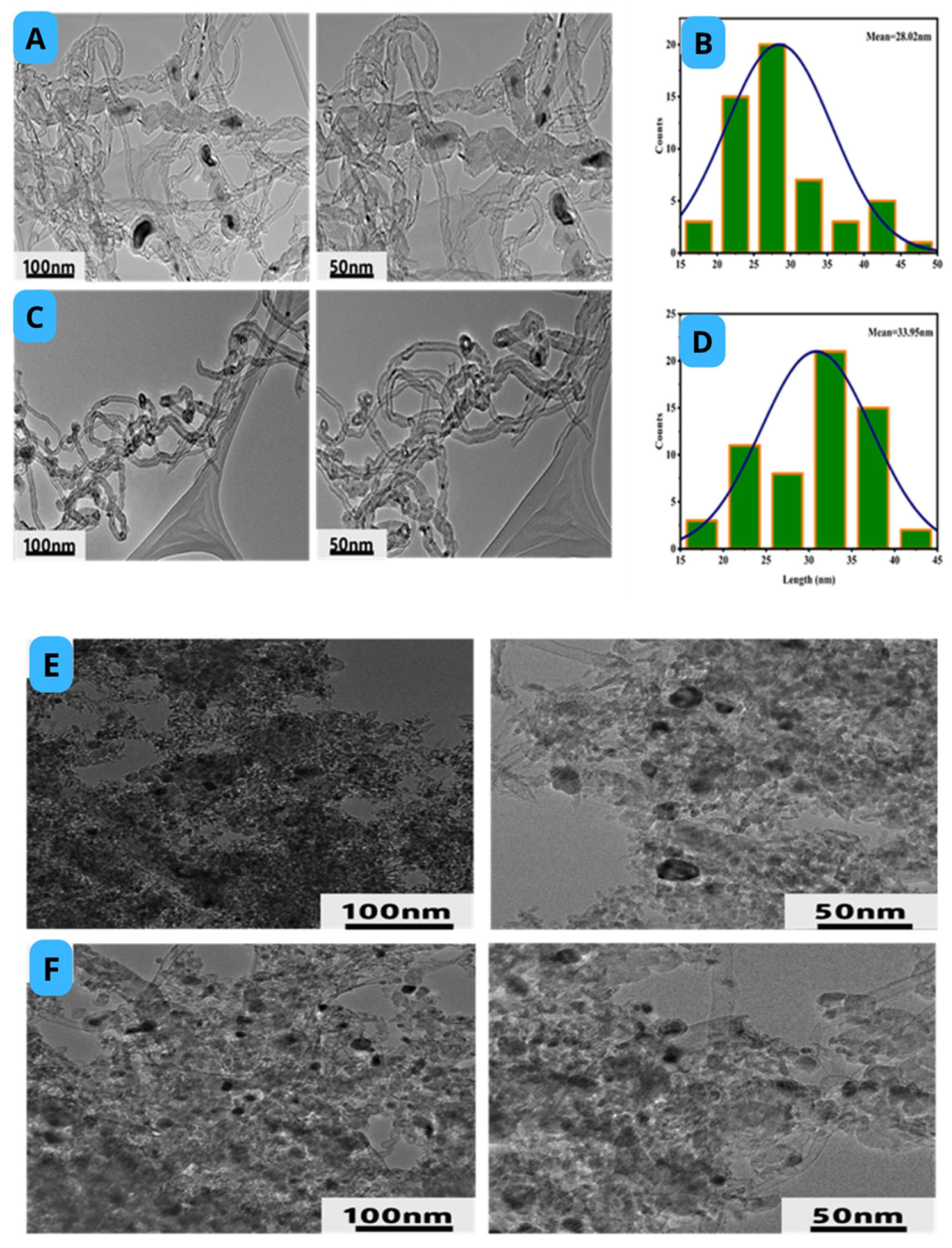
2.4. Morphology of Catalyst

The surface morphology of the fresh Fe/Ti-Al (A) and Ga-Fe/Ti-Al (B) catalysts is displayed in Figure 4 (scanning electron microscope image) and Figure 5 (transmission electron microscope image) with different magnifications. The salty texture of the catalysts was evident, but it did not change significantly upon the addition of the Ga promoter. The mean particle size over the Ga-promoted Fe/Ti-Al catalyst is larger (26.1 nm) than the particle size over the unpromoted catalyst (16.9 nm) (Figure S1).

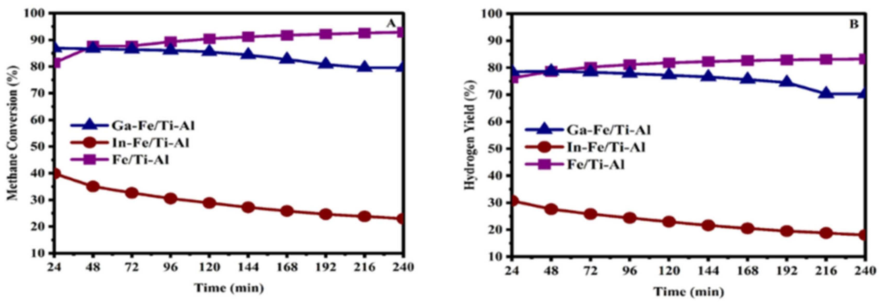
2.5. Catalytic Activity

The effects of indium and gallium on the catalytic activity for methane decomposition are displayed in Figure 6. Before the reaction, all the catalysts were activated by reducing in a H2 atmosphere at 700 °C for one h. In contrast, the activity was conducted at an operating temperature of eight hundred degrees Celsius at a gas hourly space velocity (GHSV) of 6 L gcat−1 h−1.
The Fe/Ti-Al catalyst started with an initial methane conversion and hydrogen yield of 81% and 75%, respectively, higher than the Fe/Ti-Al promoted with indium catalysts. With the increase in reaction time, the Fe/Ti-Al catalyst recorded a steep increase in methane conversion of 90% and hydrogen yield of 81% after approximately 120 min. Afterwards, the methane conversion and hydrogen yield reached a stable level and remained consistent as the reaction continued, holding steady until the completion of the reaction period. Based on the characterization results, the gallium or indium-promoted Fe/Ti-Al catalysts had wider pores in the mesoporous range and a higher density of active sites than the catalysts without dopants. The gallium-promoted Fe/Ti-Al is especially recognized for finer dispersion of iron-related phases and the higher edge of reducibility. This catalyst started with an initial methane conversion of around 88% and a hydrogen yield of 79%.
However, a drop in the methane conversion was observed at around 72 min. Over time, the methane conversion gradually decreased to 79%, achieving a 70% hydrogen yield by the end of the reaction. Even gallium-promoted catalysts had a higher density of well-dispersed active sites, but strong Ga-Fe interaction [47] could be the possible reason for the decrease in the efficiency of CH4 decomposition. The activity is further dropped on reaction progress, signifying the active sites’ shading by inert carbon. Interestingly, the Fe/Ti-Al catalyst-promoted indium displayed a different catalytic behavior than the Fe/Ti-Al and gallium-promoted catalysts. The performance of the In-Fe/Ti-Al catalyst was found to be the lowest in terms of methane conversion and hydrogen yield among the tested catalysts. As shown in Figure 6, the methane conversion started at 40% with 31% hydrogen yield, and the catalytic performance decreased gradually to 25% and 18% for methane conversion and hydrogen yield, respectively, following a reaction of 240 min. When Indium was added to the Fe-based catalyst system, the results showed lower catalytic activity, similar to that previously reported for Fischer–Tropsch synthesis [48]. Indium-promoted Fe/Ti-Al catalyst showed the least dispersion of iron-containing phases (in XRD). However, the reduction profile shows that In-Fe/Ti-Al had a higher concentration of active sites than the unpromoted catalyst. It can be assumed that indium oxide is reduced into metallic indium, which melts before reaching the CH4 decomposition temperature, which in turn covers the active sites in the Fe catalyst and renders it inactive towards the CH4 decomposition reaction. Moreover, the catalysts employed in this research are compared with various iron-based catalyst systems reported in the literature, as presented in Table 2.

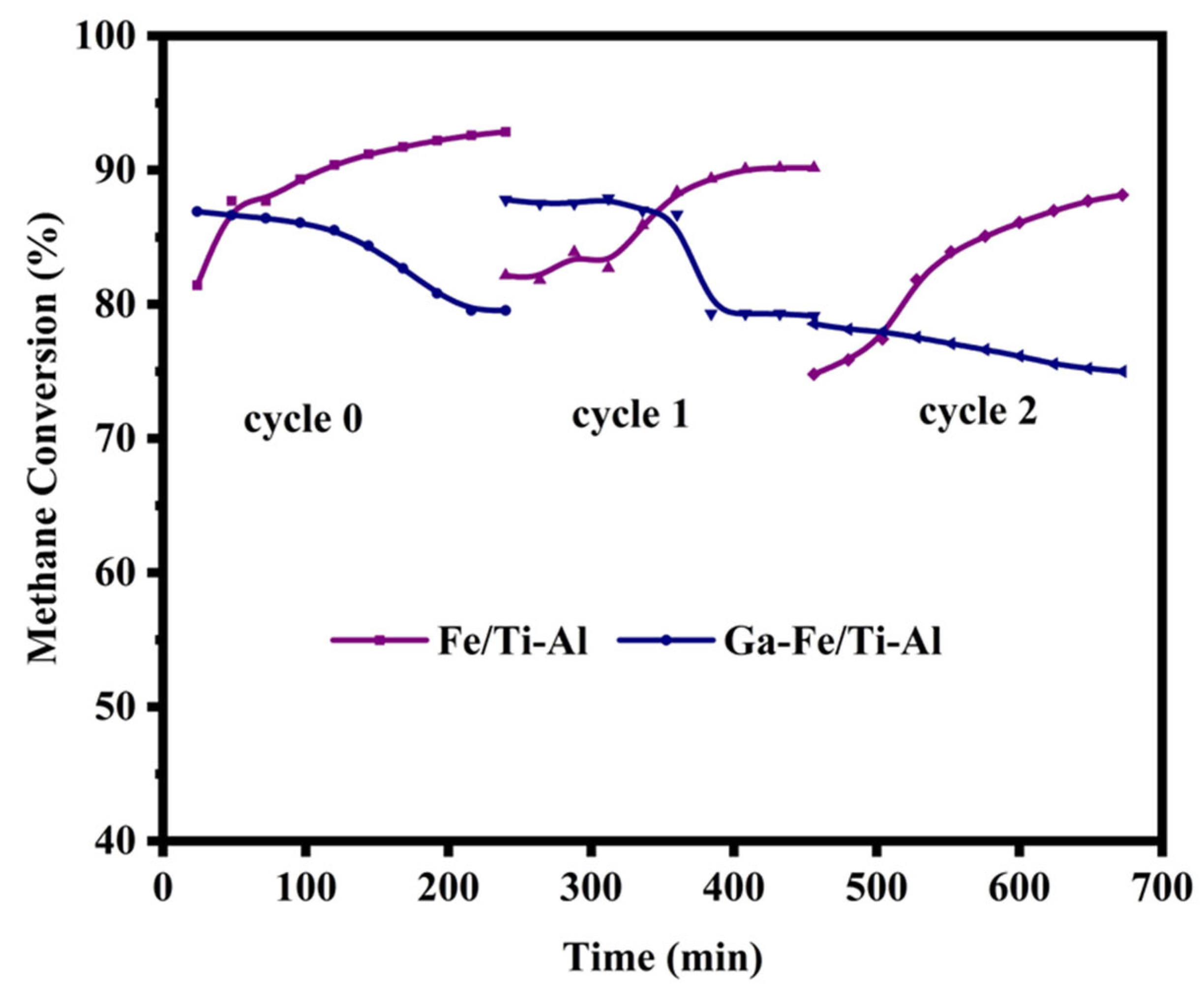
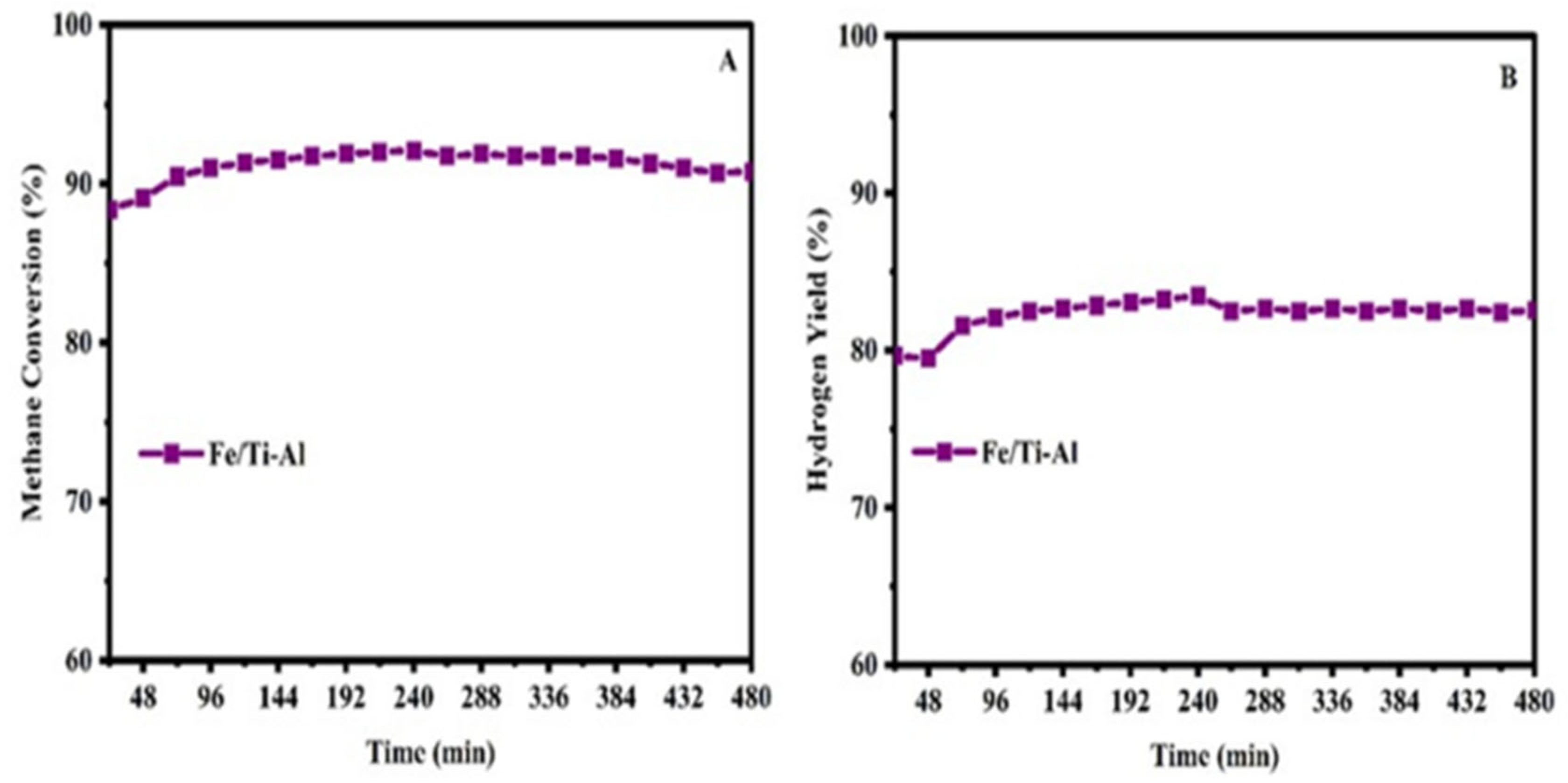
2.6. Regeneration and Long-Term Stability of the Catalysts Test

Furthermore, regeneration experiments were conducted using Fe/Ti-Al and Ga-Fe/Ti-Al catalysts. After 50 min of O₂ regeneration at 850 °C, spent catalysts were purged for 30 min using N₂. Following the purge, online gas chromatography verified that there were no COx peaks, demonstrating that the CNTs were completely oxidized. A GHSV of 6 L gcat⁻¹ h⁻¹ was then used to perform CH4 decomposition at 800 °C. Figure 7 summarizes the outcomes of the three iterations of this procedure. The Fe/Ti-Al catalyst first converted 82% of the CH4 within the first 96 min of the first cycle, reaching 90% during the second cycle, as seen in Figure 7. During the first 86 min of the third cycle, the catalyst’s conversion was a little lower at 86%, but by the end of the run, it had once again achieved 90%. Conversely, the Ga-Fe/Ti-Al catalyst began with a methane conversion of 88% in the first 144 min and gradually deactivated to 79% at the end of the second cycle (240 min). In the third cycle, as shown in Figure 7, this Ga-Fe/Ti-Al catalyst exhibited initial methane conversion the same as the end of the second cycle and then deactivated slowly to 75% at the end of the time stream. Following three cycles, 90% and 75% CH4 conversions were sustained by the Fe/Ti-Al and Ga-Fe/Ti-Al catalysts, respectively. Over fresh catalysts, the lower activity over Ga-Fe/Ti-Al (than Fe/Ti-Al) was claimed to decrease the efficiency of CH4 decomposition by Ga-Fe interaction. The same trend of activity is followed upon regeneration. A long-term experiment was carried out employing the Fe/Ti-Al catalyst at 800 °C and a GHSV of 6 L gcat⁻¹ h⁻¹ with an N₂:CH₄ ratio of 2:1 to examine catalyst stability and deactivation further. The initial CH4 conversion was 84% during the first 72 min of the 480 min run (Figure 8), and by the end of the experiment, it had risen to approximately 90%. The strong connection between the Fe particles and the titanium/alumina support is responsible for the Fe/Ti-Al catalyst’s higher activity. This metal-support interaction (MSI) prevents the sintering of Fe particles during high-temperature methane decomposition, maintaining their high dispersion and catalytic activity. Additionally, titanium and alumina’s high melting points and excellent thermal resistance ensure that the catalyst remains structurally stable during high-temperature reactions [42,43]. Furthermore, the combination of Ti-Al supports can mitigate carbon deposition on the catalyst surface, a primary cause of deactivation in methane decomposition reactions, and promote the gasification of carbon species or prevent excessive carbon buildup [44].

3. Characterization of Used Catalyst

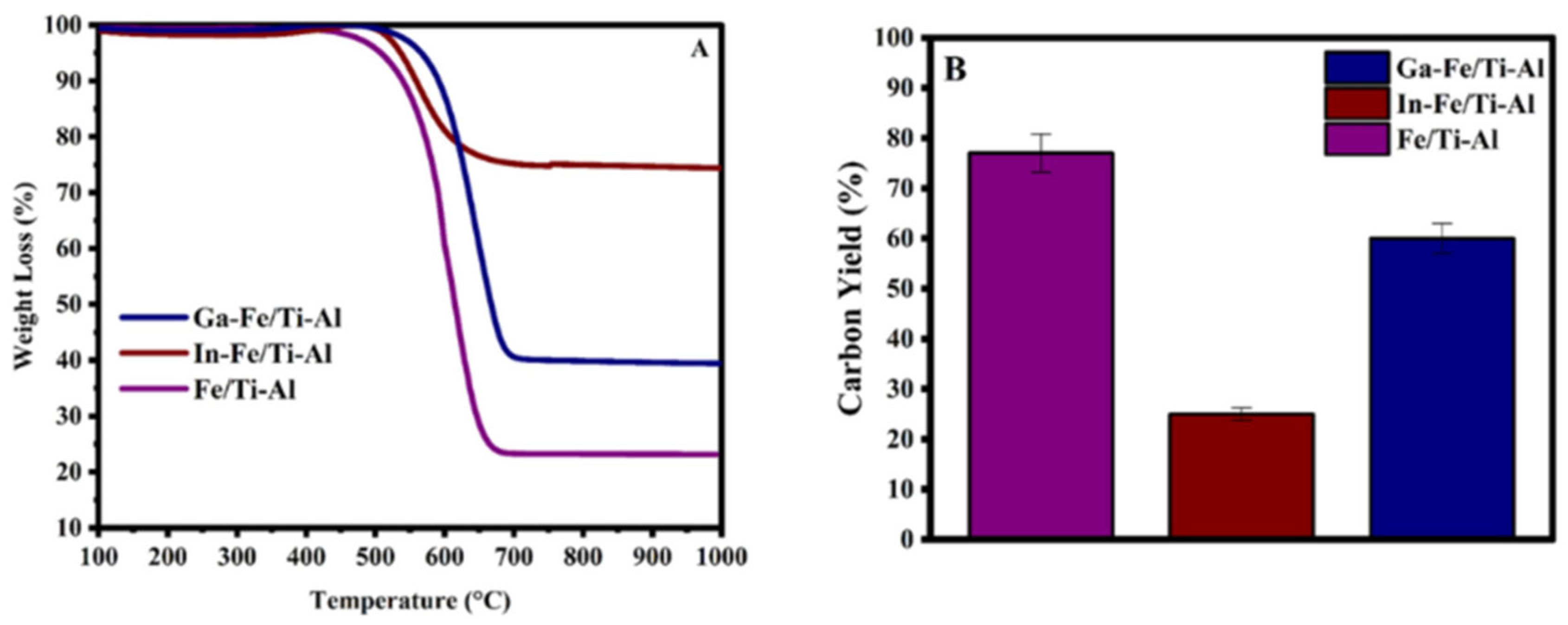
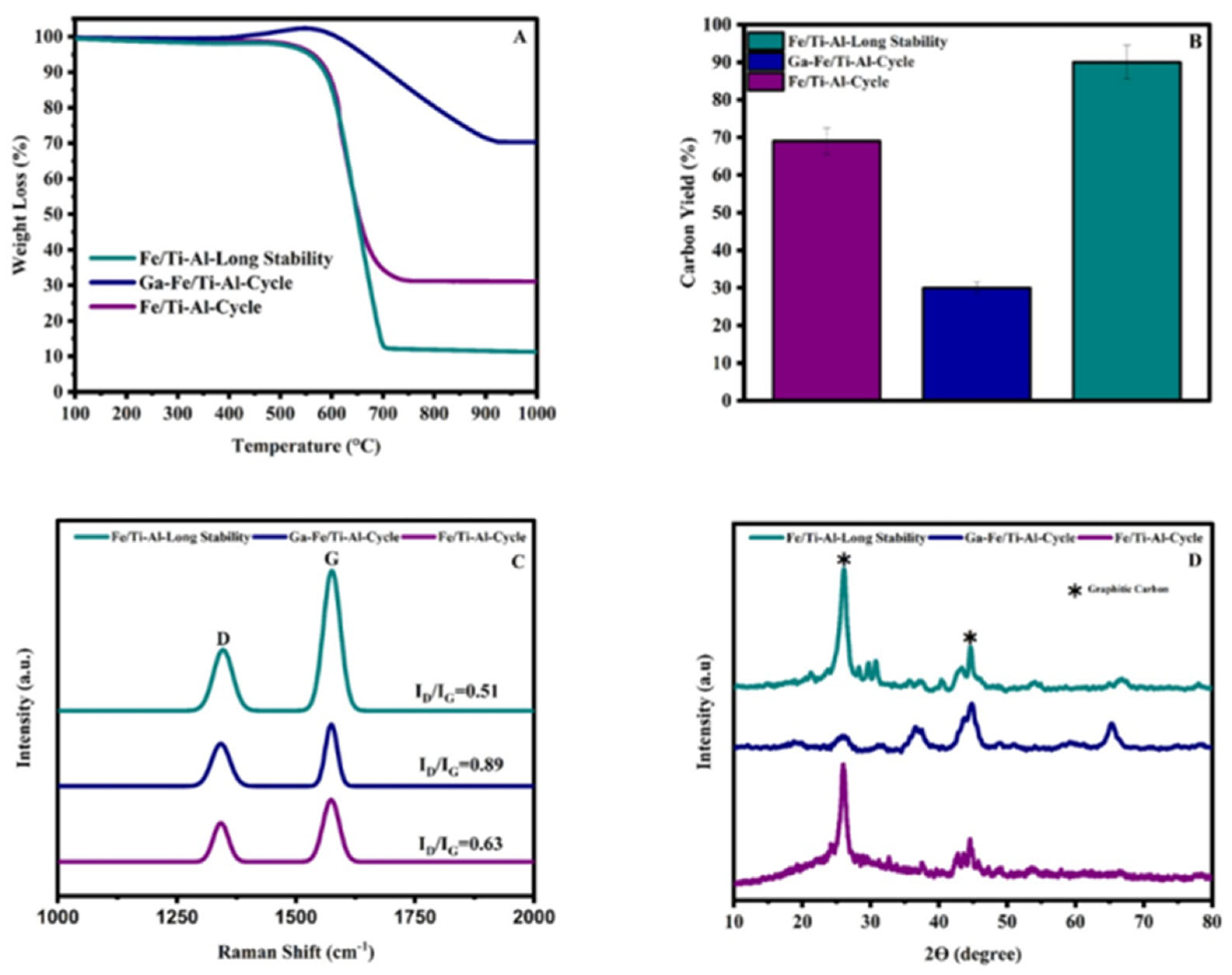
3.1. TGA-Used Catalyst

TGA analysis examines the thermal stability, purity, and quality of the as-produced carbon nanomaterials on the spent catalysts. The figure presents the TGA curves for carbon nanomaterials grown on Fe/Ti-Al and Fe/Ti-Al-promoted liquid metal catalysts. All catalysts demonstrate similar oxidation patterns with a single-step degradation process [21,53]. As can be shown in Figure 9B, the used Fe/Ti-Al and Ga-Fe/Ti-Al catalysts show significant weight loss starting around 600 °C and stabilizing around 700 °C, with types of carbon nanostructured exhibiting a higher degree of graphitization, as can be confirmed by the Raman analysis (Figure 10). In contrast, the In-Fe/Ti-Al catalyst exhibits a gradual weight loss starting at a lower temperature of around 500 °C and stabilizing around 600 °C with 25%. The relationship between carbon production and the methane conversion performance of the three catalysts is depicted in Figure 9B. In addition, there is a clear and direct relationship between the level of methane decomposition activity (Figure 6) and the resulting weight loss of accumulated carbon materials (Figure 9A).

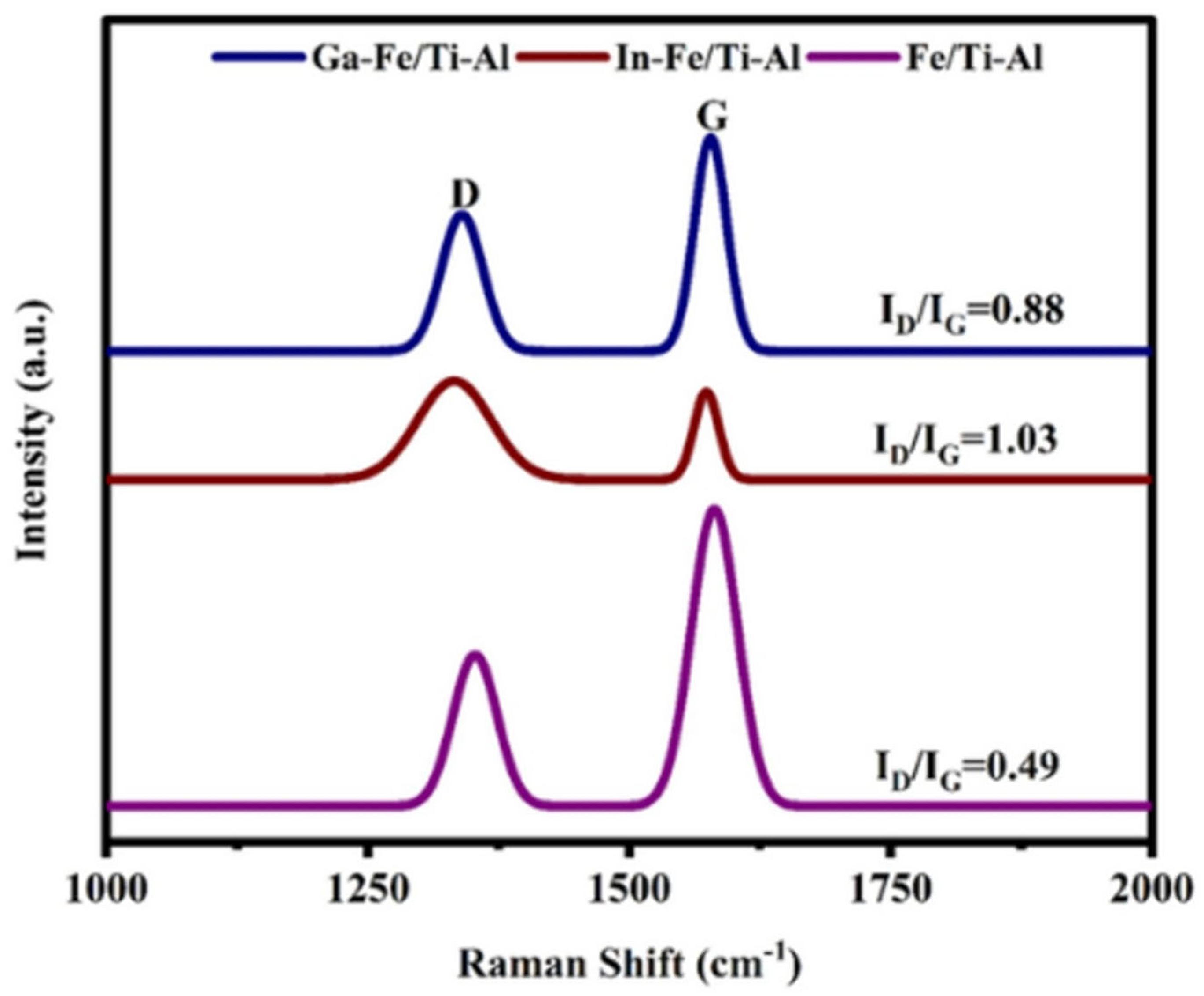
3.2. Raman Spectroscopy Used a Catalyst

Spectroscopic analysis of the spent catalysts is an efficient technique for evaluating the quality and crystallinity of the carbon nanomaterials produced on the catalyst surface. Figure 10 displays the spent catalysts’ typical Raman spectrum. All catalysts exhibit two noticeable peaks at around 1346 cm−1 and 1581 cm−1, as shown. These peaks represent the D and G bands. The D band is generally linked to disordered carbon species, including amorphous carbon and flaws in the CNT walls. Conversely, the existence of graphitic crystalline carbon is responsible for the G band [54,55]. Thus, the intensity ratio of the D band (ID) to the G band (IG) provides valuable insights into the material’s structural properties. The ID/IG ratios increased from 0.49 for Fe/Ti-Al to 0.88 for Ga-Fe/Ti-Al and 1.03 for In-Fe/Ti-Al, indicating a decrease in graphitization (or an increase in amorphicity) of the carbon.

3.3. TPO-Used Catalyst

Figure 11A shows the temperature program oxidation using oxygen (O2-TPO) for the spent catalysis samples after the complete CMD reaction step, as shown in Figure 11A. The TPO results were observed to be consistent with the TGA results. The promoted Fe/Ti-Al catalyst has the lowest carbon oxidation peak, whereas the carbon oxidation peaks for Ga-promoted Fe/Ti-Al catalysts and non-promoted catalysts are comparable.

3.4. X-Ray Diffraction Catalyst

The carbon’s structural properties were analyzed using powder X-ray diffraction (XRD); the XRD patterns of the samples after the reaction tests are illustrated in Figure 11B. The analysis identified two reflections that can be attributed to graphitic carbon structures (2θ = 26° and 44.5°) [56] and two additional distinct reflections associated with iron carbide (2θ = 54° and 67°). The used samples did not show any reflections of the hematite phase after carbon deposition, suggesting that any remaining hematite phase was reduced during the reaction. Furthermore, it was observed that incorporating indium into the Fe/Ti-Al catalysts reduced the intensity of peaks associated with crystalline carbon. The XRD results are also consistent with the TGA and TPO results, having the minimum intensity of carbon peak with Fe-In/Ti-Zr catalyst and comparable peak intensity of carbon peak with Fe-Ga/Ti-Al and Fe/Ti-Al catalysts.

3.5. Morphology-Used a Catalyst

Transmission electron microscopy (TEM) was utilized to analyze the microstructure of carbon nanotubes grown on Fe/Ti-Al catalysts. The analysis included the examination of the carbon deposited before (image A) and after regeneration (image B), as illustrated in Figure 12. Both Fe-based catalysts displayed carbon nanotubes, suggesting the development of multi-walled, parallel-oriented carbon nanotubes. The catalyst showed densely packed, multi-walled, tiny carbon nanotubes before regeneration (Figure 12A). The position of Fe components within the carbon nanofilaments is demonstrated by the dark spots that are present in every image. However, the Fe-Ga/Ti-Al Figure 12E,F displays indications of deactivation, including sintering of metal particles and possible amorphous carbon buildup, which could reduce the active surface area.
The spent Fe/Ti-Al and Ga-Fe/Ti-Al catalysts were recharacterized following regeneration and extensive stability testing. The carbon types were nanotubes, and the weight loss trend was 75% for both the regeneration and no regeneration of Fe/Ti-Al, as shown in Figure 13. In contrast to a catalyst that has not been regenerated, the spent Ga-Fe/Ti-Al regenerated catalyst exhibits a minimal carbon deposit. Furthermore, the weight loss during the extended stability period on Fe/Ti-Al is around 90%, indicating that more carbon was deposited than on either catalyst before or during regeneration. According to Raman’s research, the ID/IG ratios created high-quality carbon nanotubes (CNTs), as seen by the Fe/Ti-Al catalysts’ ID/IG ratios of 0.51 and 0.69 during regeneration and lengthy stability tests, respectively. An ID/IG ratio of 0.89 suggested that the Ga-Fe/Ti-Al catalyst’s carbon nanotubes had a lesser degree of crystallinity and graphitization. Diffraction peaks at roughly 26° and 44.5° were found by XRD analysis, which indicated the production of graphitic carbon on the catalyst surfaces. In contrast to the Ga-Fe/Ti-Al catalyst, the regenerated Fe/Ti-Al catalyst and the identical catalyst following the lengthy stability test had a noticeably higher intensity in the distinctive graphitic carbon plane, indicating stronger crystallinity. On the other hand, by the TGA and Raman investigations, the graphitic carbon peak of the Ga-Fe/Ti-Al catalyst displayed a comparatively low intensity. In conclusion, following the long-term stability investigation, the Fe/Ti-Al catalyst showed the highest degree of carbon crystallinity and the largest carbon deposition.

4. Supplies and Preparation

4.1. Supplies

Alfa Aesar in Karlsruhe, Germany, is the supplier of the chemicals utilized in this experiment. All of the precursors were used without any additional processing. The chemicals acquired from Sigma-Aldrich included iron nitrate nonahydrate Fe(NO3)3·9H2O, titanium (IV) isopropoxide Ti[OCH(CH3)2]4·(TTIP), alumina nitrate nonahydrate Al(NO3)3·9H2O, and gallium nitrate hydrate Ga(NO3)3·xH2O and indium nitrate hydrate In(NO3)3·xH2O. The experiment also made use of a crucible, a crusher, and deionized water.

4.2. Catalyst Preparation

Iron supported on titania-alumina catalysts promoted with liquid metal (gallium and indium) was prepared using the hydrothermal method. Typically, the desired amount of titanium (IV) isopropoxide (TTIP) (1.423 g) and 25 mL of ethanol are stirred at room temperature for one h, and HCl solution (0.5 M concentration) is added dropwise and continuously stirred for six h. Then, the stoichiometric amounts of Al(NO3)3·9H2O (4.415 g), Fe(NO3)3·9H2O (2.89 g), Ga(NO3)3·xH2O (0.0458 g), and In(NO3)3·xH2O (0.0328 g) is dissolved separately in distilled water and stirred continuously for two h, and added dropwise to the (TTIP) solution and continuously stirred for one hour. The NaOH solution (2 M concentration) was then added and thoroughly mixed to produce a homogeneous mixture with pH = 10. After that, it is moved to a 100 mL stainless-steel autoclave lined with Teflon, heated for 12 h at 180 °C in an oven, and then allowed to cool to room temperature. After filtering and drying at 100 °C for 12 h, the solid is heated in an air-conditioned muffle furnace at a rate of 7 °C per minute for 5 h, reaching 500 °C, as shown in the schematic diagram of preparation in Figure 14. The obtained catalysts are 20 wt.% Fe/20 wt.% Ti-Al, 2.5 wt.% Ga/(20-Fe/20Ti-Al), and 2.5 wt.% In/(20-Fe/20Ti-Al), and referred to, respectively, as Fe/Ti-Al, Ga-Fe/Ti-Al, and In-Fe/Ti-Al.

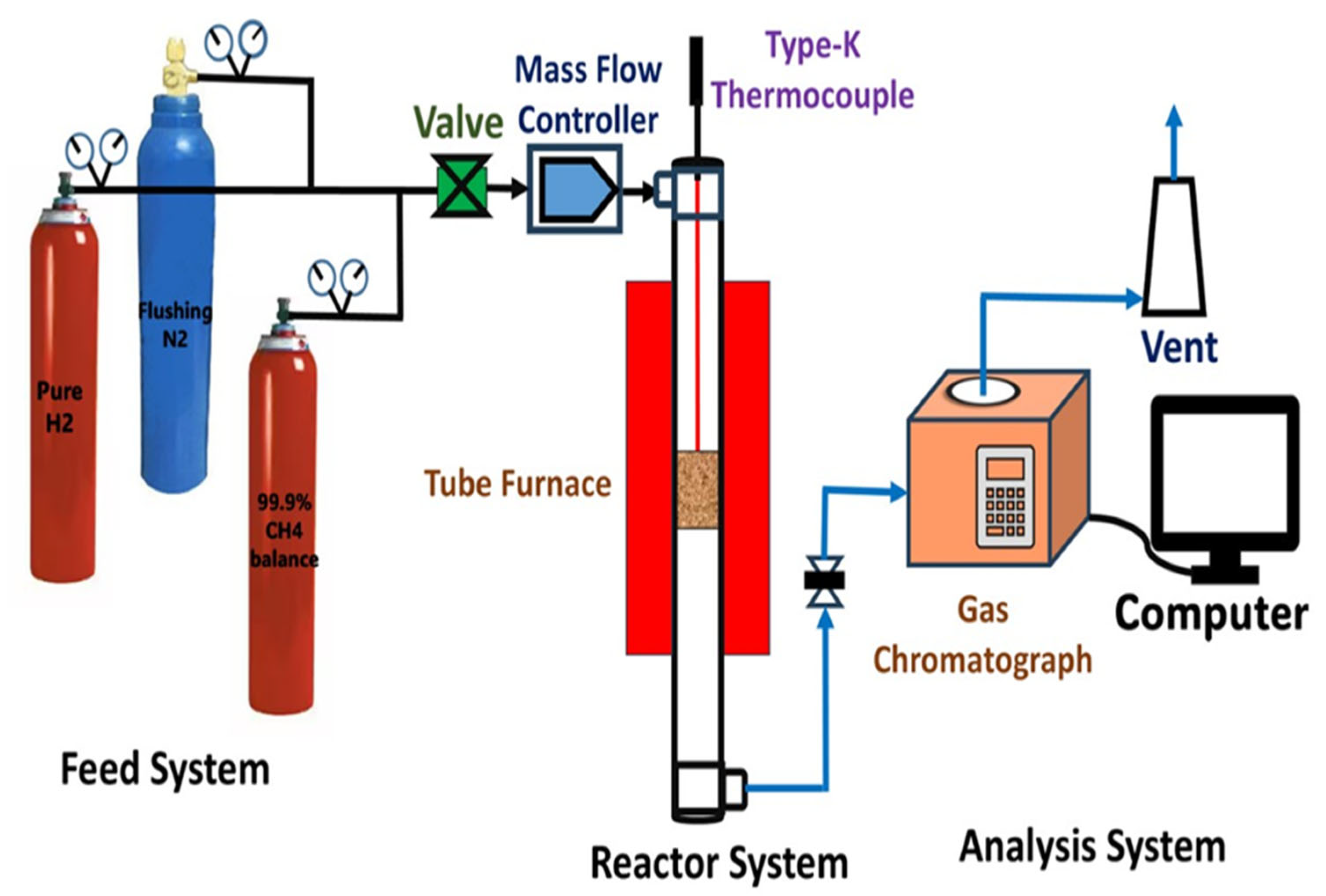
4.3. Catalytic Reactor Set Up

The experimental setup for the catalytic decomposition of methane is illustrated in Figure 15. The reaction involved two distinct gas sources: CH4 and N2. These gases were directed from their storage cylinders to a common mixing point. CH4 initiated the hydrogen production process. N2 functioned as the standard dilution stream; in addition, before the reaction occurred, hydrogen gas was utilized to convert the metal oxide into its metallic state to serve as the active catalyst. The stainless-steel fixed-bed with a 9 mm inner diameter and 300 mm length was used as the reactor and inserted in a vertical furnace with well-temperature control. The temperature readings were taken from a K-type thermocouple attached to the fixed-bed reactor wall. The activity of the synthesized catalysts was tested at 800 °C under atmospheric pressure; the weight of the synthesized catalysts is 0.15 g with the physical condition of reduction is 30 mL/min of hydrogen at 700 °C and the mixture of methane and nitrogen will pass through the bed reactor with 15 mL/min of the mixture CH4:N2 (5:10 mL/min) with a total gas hourly space velocity (GHSV) of 6 L g−1 h−1. Furthermore, the regeneration of the spent catalyst is carried out at the same reactor with a flow of 15 mL/min of oxygen at 850 °C. The gases after the reaction were analyzed using a gas chromatograph Thermal Conductivity Detector (Shimadzu GC 2004, Shimadzu Corporation, Tokyo, Japan) connected to the reactor outlet. Argon was used as the gas carrier for the Gas-Chromatography (GC, Shimadzu Corporation, Tokyo, Japan). After collecting the data, the methane conversion, hydrogen yield, and carbon yield will be calculated using the following equation.
M e t h a n e   C o n v e r s i o n % = C H 4 i n C H 4 o u t C H 4 i n 100
H 2   Y i e l d % = [ m o l e s   o f   H 2   P r o d u c e d ] [ 2 m o l e s   o f   C H 4   i n   t h e   f e e d ] 100
C a r b o n   Y i e l d % = W e i g h t   o f   d e p o s i t e d   c a r b o n   o n   t h e   c a t a l y s t W e i g h t   o f   m e t a l   c a t a l y s t 100

4.4. Fresh Catalyst Characterization

The Brunauer–Emmett–Teller (BET) was used to determine the specific surface area and the porosity of the fresh catalyst with an analyzer called Micro-meristic Tristar II 3020, Micromeritics Instrument Corporation, Georgia, USA. For each analysis, 0.2 g of the catalyst was degassed at 250 °C for three h to eliminate any moisture content and other adsorbed gases.
Temperature-programmed reduction (TPR) is an analytical technique used to understand reducibility and the behavior of metal oxides of fresh catalysts. The Micromeritics Auto Chem II 2920Micromeritics Instrument Corporation, Georgia, USA, was used, and a tube was filled with 70 mg of the catalyst samples. Then, an H2/Ar mixture flowing at 40 mL/min was introduced as the furnace temperature was raised to 1000 °C at 10 °C/min. A cold trap within the machine removed the water produced during the reduction, while a thermal conductivity detector recorded the H2 consumed.
X-ray diffraction (XRD) is a highly effective tool for determining the crystalline phases in a fresh catalyst and for identifying any impurity phases that could impact the catalyst’s performance. The Miniflex Rigaku diffractometer (Rigaku Corporation. Akishima-shi, Tokyo, Japan) was used with Cu Ka X-ray radiation operating at 40 kV and 40 mA. The diffraction 2θ angle range was set to 10–80 with a step size of 0.01. The raw data file from the instrument was analyzed using X’pert High Score Plus software (Malvern Panalytical B.V., Almelo, The Netherlands). The JCPDS data bank was used to match different phases with their corresponding scores.

4.5. Post-Catalyst Characterization

Thermogravimetric Analysis (TGA) is a crucial technique used in the characterization of catalysts. It measures changes in a material’s mass as a function of temperature or time under a controlled atmosphere. The quantity of carbon deposits was determined using a Shimadzu Thermogravimetric Analyzer (TGA), Shimadzu Corporation, Tokyo, Japan. The process involved heating 10–15 mg of the used catalysts from room temperature to 1000 °C at a heating rate of 20 °C/min. The weight difference was recorded by the machine.
Temperature-programmed oxidation (TPO) is significantly valuable for obtaining information about the nature of various carbonaceous species present on the catalyst surface. The Micromeritics Auto Chem II 2920, Micromeritics Instrument Corporation, Georgia, USA will be used. The spent catalysts underwent the same pre-treatment as in TPR, and the analysis was conducted over a temperature range of 50–1000 °C under the flow of a 10% O2/He mixture at 40 mL/min.
Raman spectroscopy and X-ray diffraction (XRD) are effective analytical techniques for identifying and characterizing carbon deposits on the used catalysts. It can differentiate between various forms of carbon (e.g., amorphous carbon, graphitic carbon) and offer insights into the composition of these deposits. The type of carbon deposited and the graphitization degree were determined using a JASCO laser Raman spectrometer from Tokyo, Japan. The spectrometer used an excitation beam with a wavelength of 532 nm. In addition, the crystalline carbon is determined using XRD analysis using the method described in the previous section.
SEM (JEOL Ltd., Akishima, Tokyo, Japan) and TEM (Thermo Fisher Scientific Inc. Waltham, MA, USA) measurements were conducted on the fresh and spent samples to inspect the morphology of the dispersion of active metal on the support for the fresh catalyst and the deposited carbon types for the spent catalyst. The transmission electron microscope was used for this purpose, operated at an accelerating voltage of 120 KV. Before TEM imaging, the samples were prepared by dispersing them in absolute ethanol and sonicating them for 30 min. Afterward, the dispersion was drop-casted on a TEM grid coated with a sample and left to dry at room temperature.

5. Conclusions

The iron supported on a titanium-alumina catalyst was prepared using a hydrothermal approach. This study looked into how the inclusion of liquid metal affected the catalytic qualities of materials employed in the decomposition of CH4. The inclusion of liquid metal dramatically changed the surface area and pore size distribution of the iron supported on the titanium-alumina, which in turn affected the metal’s dispersion and use. In terms of CH4 conversion, stability, and regeneration, the Fe/Ti-Al catalyst outperformed catalysts supported by liquid metals. The Fe/Ti-Al catalyst produced 81% H2 and the greatest CH4 conversion (91%) of any catalyst. Among the liquid metal-promoted catalysts, Ga-Fe/Ti-Al displayed comparatively better CH4 conversion activity than In-Fe/Ti-Al. Notably, both Fe/Ti-Al and Ga-Fe/Ti-Al produced base-growth carbon nanotubes, which are useful for capturing without depleting catalyst sites. The Fe/Ti-Al catalyst can still produce base-growth CNTs and show strong CH4 conversions of 90% after three cycles. With a 90% CH4 conversion and a 93% production of highly crystalline carbon nanotubes, the extended stability test further demonstrates exceptional stability and activity for Fe/Ti-Al for up to 8 h. This study illustrates the development of reusable and reasonably priced catalysts for converting CH4 to H2 and the selective catalytic reduction of COx emissions in power plants.

Supplementary Materials

The following supporting information can be downloaded at: https://www.mdpi.com/article/10.3390/catal15070631/s1, Figure S1: SEM images of the fresh Fe/Ti-Al (A) & Ga-Fe/Ti-Al (C) catalyst at different magnifications with EDX analysis (B) & (D) respectively.

Author Contributions

Conceptualization, H.A., A.H.F. and S.F.A.; Methodology, H.A. and A.S.A.-F.; Software, H.A., S.F.A., F.A.A.A. and A.E.A. Validation, A.E.A., A.S.A.-F., A.E.A. and A.H.F.; Formal analysis, H.A., S.F.A., A.B. and A.E.A.; Investigation, H.A., A.B. and S.F.A.; Resources, A.S.A.-F., T.S.A. and A.B.; Data curation, H.A., A.I.O., A.B. and A.H.F.; Writing—original draft preparation, H.A.; Writing—review and editing, A.E.A., S.F.A., T.S.A., A.B., A.A.I. and A.S.A.-F.; Visualization, H.A., A.E.A., A.A.I., T.S.A., A.B. and A.S.A.-F.; Supervision, A.H.F., F.A.A.A. and A.S.A.-F.; Project administration, A.S.A.-F., A.E.A., A.I.O. and A.H.F.; Funding acquisition, A.H.F., A.I.O. and A.B. All authors have read and agreed to the published version of the manuscript.

Funding

This paper was funded by the Ongoing Research Funding program, (ORF-2025-254, King Saud University, Riyadh, Saudi Arabia, and the Researchers Supporting Project number (PNURSP2025R230), Princess Nourah bint Abdulrahman University, Riyadh, Saudi Arabia.

Data Availability Statement

The raw data supporting the conclusions of this article will be made available by the authors upon request.

Acknowledgments

The authors would like to extend their sincere appreciation to the Ongoing Research Funding program (ORF-2025-254, King Saud University, Riyadh, Saudi Arabia). Also, authors would like to extend their sincere appreciation to the Princess Nourah bint Abdulrahman University Researchers Supporting Project number (PNURSP2025R230), Princess Nourah bint Abdulrahman University, Riyadh, Saudi Arabia.

Conflicts of Interest

The authors declare that they have no known competing financial interests or personal relationships that could have appeared to influence the work reported in this paper.

References

  1. Xuan, G.; Liu, F.; Zhang, F.; Hu, Y.; Miao, J.; Yang, L. Mechanism of Improving the Stability of Activated Carbon Catalyst by Trace H2S Impurities in Natural Gas for Hydrogen Production from Methane Decomposition. Fuel 2021, 299, 120884. [Google Scholar] [CrossRef]
  2. Gamal, A.; Eid, K.; El-Naas, M.H.; Kumar, D.; Kumar, A.; Kumar, M.H.; Kumar, D.; Catalytic, A. Catalytic Methane Decomposition to Carbon Nanostructures and CO X-Free Hydrogen: A Mini-Review. Nanomaterials 2021, 11, 1226. [Google Scholar] [CrossRef]
  3. Barbir, F. Transition to Renewable Energy Systems with Hydrogen as an Energy Carrier. Energy 2009, 34, 308–312. [Google Scholar] [CrossRef]
  4. Amin, A.M.; Croiset, E.; Epling, W. Review of Methane Catalytic Cracking for Hydrogen Production. Int. J. Hydrogen Energy 2011, 36, 2904–2935. [Google Scholar] [CrossRef]
  5. Torres, D.; Pinilla, J.L.; Suelves, I. Screening of Ni-Cu Bimetallic Catalysts for Hydrogen and Carbon Nanofilaments Production via Catalytic Decomposition of Methane. Appl. Catal. A Gen. 2018, 559, 10–19. [Google Scholar] [CrossRef]
  6. Balyan, S.; Jiang, C.; Caiola, A.; Hu, J. Microwave Catalytic Conversion of Acetylene for Co-Production of Hydrogen and Carbon Nanotubes. Chem. Eng. J. 2023, 454, 140115. [Google Scholar] [CrossRef]
  7. Elbadawi, A.H.; Ge, L.; Li, Z.; Liu, S.; Wang, S.; Zhu, Z. Catalytic Partial Oxidation of Methane to Syngas: Review of Perovskite Catalysts and Membrane Reactors. Catal. Rev. Sci. Eng. 2021, 63, 1–67. [Google Scholar] [CrossRef]
  8. Barelli, L.; Bidini, G.; Gallorini, F.; Servili, S. Hydrogen Production through Sorption-Enhanced Steam Methane Reforming and Membrane Technology: A Review. Energy 2008, 33, 554–570. [Google Scholar] [CrossRef]
  9. Tezel, E.; Figen, H.E.; Baykara, S.Z. Hydrogen Production by Methane Decomposition Using Bimetallic Ni–Fe Catalysts. Int. J. Hydrogen Energy 2019, 44, 9930–9940. [Google Scholar] [CrossRef]
  10. Catalan, L.J.J.; Rezaei, E. Coupled Hydrodynamic and Kinetic Model of Liquid Metal Bubble Reactor for Hydrogen Production by Noncatalytic Thermal Decomposition of Methane. Int. J. Hydrogen Energy 2020, 45, 2486–2503. [Google Scholar] [CrossRef]
  11. Al -Fatesh, A.S.; Kasim, S.O.; Ibrahim, A.A.; Al-Awadi, A.S.; Abasaeed, A.E.; Fakeeha, A.H.; Awadallah, A.E. Catalytic Methane Decomposition over ZrO2 Supported Iron Catalysts: Effect of WO3 and La2O3 Addition on Catalytic Activity and Stability. Renew. Energy 2020, 155, 969–978. [Google Scholar] [CrossRef]
  12. Qian, J.X.; Chen, T.W.; Enakonda, L.R.; Liu, D.B.; Mignani, G.; Basset, J.M.; Zhou, L. Methane Decomposition to Produce COx-Free Hydrogen and Nano-Carbon over Metal Catalysts: A Review. Int. J. Hydrogen Energy 2020, 45, 7981–8001. [Google Scholar] [CrossRef]
  13. Khan, U.M.; Sarmad, Q.; Anwar, M.; Khoja, A.H.; Muhammed Ali, S.A.; Khan, Z.S.; Hassan, M.; Shakir, S. Synthesis of Cobalt Loaded Double Perovskite Sr2TiFeO6-δ (STF) as a Stable Catalyst for Enhanced Hydrogen Production via Methane Decomposition. Int. J. Energy Res. 2021, 45, 20073–20088. [Google Scholar] [CrossRef]
  14. Rastegarpanah, A.; Rezaei, M.; Meshkani, F.; Zhang, K.; Zhao, X.; Pei, W.; Liu, Y.; Deng, J.; Arandiyan, H.; Dai, H. Influence of Group VIB Metals on Activity of the Ni/MgO Catalysts for Methane Decomposition. Appl. Catal. B Environ. 2019, 248, 515–525. [Google Scholar] [CrossRef]
  15. Ibrahim, A.A.; Fakeeha, A.H.; Al-Fatesh, A.S.; Abasaeed, A.E.; Khan, W.U. Methane Decomposition over Iron Catalyst for Hydrogen Production. Int. J. Hydrogen Energy 2015, 40, 7593–7600. [Google Scholar] [CrossRef]
  16. Pudukudy, M.; Yaakob, Z.; Takriff, M.S. Methane Decomposition over Pd Promoted Ni/MgAl2O4 Catalysts for the Production of COx Free Hydrogen and Multiwalled Carbon Nanotubes. Appl. Surf. Sci. 2015, 356, 1320–1326. [Google Scholar] [CrossRef]
  17. Hasnan, N.S.N.; Timmiati, S.N.; Lim, K.L.; Yaakob, Z.; Kamaruddin, N.H.N.; Teh, L.P. Recent Developments in Methane Decomposition over Heterogeneous Catalysts: An Overview. Mater Renew Sustain. Energy 2020, 9, 1–18. [Google Scholar] [CrossRef]
  18. Yergaziyeva, G.; Makayeva, N.; Abdisattar, A.; Yeleuov, M.; Soloviev, S.; Anissova, M.; Taurbekov, A.; Dossumov, K.; Akkazin, E.; Daulbayev, C. Electrochemical Synthesis of Fe-Containing Composite for Decomposition of Methane into COx-Free Hydrogen and Nano-Carbon. Chem. Pap. 2022, 76, 1–13. [Google Scholar] [CrossRef]
  19. Wang, P.; Zhu, H.; Huang, M.; Wan, C.; Li, D.; Jiang, L. Catalytic Methane Decomposition to Hydrogen and Carbon over Hydrotalcite-Derivative Composition-Uniform and Sintering-Resistant Ni-Fe/Al2O3 Alloy Catalysts. Int. J. Energy Res. 2022, 46, 16810–16822. [Google Scholar] [CrossRef]
  20. Zhou, L.; Enakonda, L.R.; Harb, M.; Saih, Y.; Aguilar-Tapia, A.; Ould-Chikh, S.; Hazemann, J.L.; Li, J.; Wei, N.; Gary, D.; et al. Fe Catalysts for Methane Decomposition to Produce Hydrogen and Carbon Nano Materials. Appl. Catal. B Environ. 2017, 208, 44–59. [Google Scholar] [CrossRef]
  21. Alharthi, A.I.; Abdel-Fattah, E.; Alotaibi, M.A.; Al-Shalwi, M.N. Facile Modification of Cobalt Ferrite by SiO2 and H-ZSM-5 Support for Hydrogen and Filamentous Carbon Production from Methane Decomposition. Int. J. Energy Res. 2022, 46, 17497–17510. [Google Scholar] [CrossRef]
  22. Fakeeha, A.H.; Kasim, S.O.; Ibrahim, A.A.; Al-Awadi, A.S.; Alzahrani, E.; Abasaeed, A.E.; Awadallah, A.E.; Al-Fatesh, A.S. Methane Decomposition Over ZrO2-Supported Fe and Fe–Ni Catalysts—Effects of Doping La2O3 and WO3. Front. Chem. 2020, 8, 527057. [Google Scholar] [CrossRef]
  23. Abdel-Fattah, E.; Alotaibi, M.A.; Alharthi, A.I. Thermo-Catalytic Methane Decomposition over Unsupported Fe–Al and Co–Al Catalysts for Hydrogen and Carbon Nanostructures Production. Int. J. Hydrogen Energy 2024, 64, 685–694. [Google Scholar] [CrossRef]
  24. Mohamed, A.T.; Ali, S.; Kumar, A.; Mondal, K.C.; El-Naas, M.H. Evaluation of Highly Active and Stable SiO2 Supported Fe-Based Catalysts for the Catalytic Methane Decomposition into COx Free Hydrogen and CNTs. Catal. Commun. 2023, 180, 106703. [Google Scholar] [CrossRef]
  25. Pashchenko, D. Thermodynamic Equilibrium Analysis of Steam Methane Reforming Based on a Conjugate Solution of Material Balance and Law Action Mass Equations with the Detailed Energy Balance. Int. J. Energy Res. 2020, 44, 438–447. [Google Scholar] [CrossRef]
  26. Rein, D.; Friedel Ortega, K.; Weidenthaler, C.; Bill, E.; Behrens, M. The Roles of Co-Precipitation PH, Phase-Purity and Alloy Formation for the Ammonia Decomposition Activity of Ga-Promoted Fe/MgO Catalysts. Appl. Catal. A Gen. 2017, 548, 52–61. [Google Scholar] [CrossRef]
  27. Al-Fatesh, A.S.; Ibrahim, A.A.; AlSharekh, A.A.M.; Alqahtani, F.S.; Kasim, S.O.; Al-Zahrani, S.A.; Fakeeha, A.H. Methane Decomposition over Strontium Promoted Iron Catalyst: Effect of Different Ratio of Al/Si Support on Hydrogen Yield. Chem. Eng. Commun. 2020, 207, 1148–1156. [Google Scholar] [CrossRef]
  28. Bao, A.; Ma, Y.; Guo, X.; Wang, J.; Zhao, Y.; Liu, Z.; Wang, Y.; Liu, X.; Zhang, Y. Tunable Electronic and Optical Properties of a Type-II GaP/SiH van Der Waals Heterostructure as Photocatalyst: A First-Principles Study. Int. J. Hydrogen Energy 2024, 88, 1256–1266. [Google Scholar] [CrossRef]
  29. Pudukudy, M.; Yaakob, Z.; Jia, Q.; Takriff, M.S. Catalytic Decomposition of Methane over Rare Earth Metal (Ce and La) Oxides Supported Iron Catalysts. Appl. Surf. Sci. 2019, 467–468, 236–248. [Google Scholar] [CrossRef]
  30. Tang, L.; Yamaguchi, D.; Burke, N.; Trimm, D.; Chiang, K. Methane Decomposition over Ceria Modified Iron Catalysts. Catal. Commun. 2010, 11, 1215–1219. [Google Scholar] [CrossRef]
  31. Fakeeha, A.H.; Al-Fatesh, A.S.; Khan, W.U.; Ibrahim, A.A.; Al-Otaibi, R.L.; Abasaeed, A.E. Suitability of Titania and Magnesia as Support for Methane Decomposition Catalyst Using Iron as Active Materials. J. Chem. Eng. Jpn. 2016, 49, 552–562. [Google Scholar] [CrossRef]
  32. Lázaro, M.J.; Echegoyen, Y.; Alegre, C.; Suelves, I.; Moliner, R.; Palacios, J.M. TiO2 as Textural Promoter on High Loaded Ni Catalysts for Methane Decomposition. Int. J. Hydrogen Energy 2008, 33, 3320–3329. [Google Scholar] [CrossRef]
  33. Dickey, M.D. Emerging Applications of Liquid Metals Featuring Surface Oxides. ACS Appl. Mater. Interfaces 2014, 6, 18369–18379. [Google Scholar] [CrossRef]
  34. Taccardi, N.; Grabau, M.; Debuschewitz, J.; Distaso, M.; Brandl, M.; Hock, R.; Maier, F.; Papp, C.; Erhard, J.; Neiss, C.; et al. Gallium-Rich Pd–Ga Phases as Supported Liquid Metal Catalysts. Nat. Chem. 2017, 9, 862–867. [Google Scholar] [CrossRef] [PubMed]
  35. Geißler, T.; Plevan, M.; Abánades, A.; Heinzel, A.; Mehravaran, K.; Rathnam, R.K.; Rubbia, C.; Salmieri, D.; Stoppel, L.; Stückrad, S.; et al. Experimental Investigation and Thermo-Chemical Modeling of Methane Pyrolysis in a Liquid Metal Bubble Column Reactor with a Packed Bed. Int. J. Hydrogen Energy 2015, 40, 14134–14146. [Google Scholar] [CrossRef]
  36. Upham, D.C.; Agarwal, V.; Khechfe, A.; Snodgrass, Z.R.; Gordon, M.J.; Metiu, H.; McFarland, E.W. Catalytic Molten Metals for the Direct Conversion of Methane to Hydrogen and Separable Carbon. Science 2017, 358, 917–921. [Google Scholar] [CrossRef]
  37. Rahman, S.; Santra, C.; Kumar, R.; Bahadur, J.; Sultana, A.; Schweins, R.; Sen, D.; Maity, S.; Mazumdar, S.; Chowdhury, B. Highly Active Ga Promoted Co-HMS-X Catalyst towards Styrene Epoxidation Reaction Using Molecular O2. Appl. Catal. A Gen. 2014, 482, 61–68. [Google Scholar] [CrossRef]
  38. Palmer, C.; Tarazkar, M.; Kristoffersen, H.H.; Gelinas, J.; Gordon, M.J.; McFarland, E.W.; Metiu, H. Methane Pyrolysis with a Molten Cu-Bi Alloy Catalyst. ACS Catal. 2019, 9, 8337–8345. [Google Scholar] [CrossRef]
  39. Plevan, M.; Geißler, T.; Abánades, A.; Mehravaran, K.; Rathnam, R.K.; Rubbia, C.; Salmieri, D.; Stoppel, L.; Stückrad, S.; Wetzel, T. Thermal Cracking of Methane in a Liquid Metal Bubble Column Reactor: Experiments and Kinetic Analysis. Int. J. Hydrogen Energy 2015, 40, 8020–8033. [Google Scholar] [CrossRef]
  40. Ahmed, H.; Fakeeha, A.H.; Al-Alweet, F.M.; Abasaeed, A.E.; Ibrahim, A.A.; Kumar, R.; Saeed, A.M.M.; Al-Fatesh, A.S. Methane Decomposition over a Titanium-Alumina and Iron Catalyst Assisted by Lanthanides to Produce High-Performance COx-Free H2 and Carbon Nanotubes. Catalysts 2025, 15, 77. [Google Scholar] [CrossRef]
  41. Leofanti, G.; Padovan, M.; Tozzola, G.; Venturelli, B. Surface Area and Pore Texture of Catalysts. Catal. Today 1998, 41, 207–219. [Google Scholar] [CrossRef]
  42. Al-Fatesh, A.S.; Vadodariya, D.M.; Bayazed, M.O.; Osman, A.I.; Ibrahim, A.A.; Fakeeha, A.H.; Alanazi, Y.M.; Abasaeed, A.E.; Kumar, R. Optimizing Hydrogen Production: Influence of Promoters in Methane Decomposition on Titania-Modified-Zirconia Supported Fe Catalyst. ACS Omega 2024, 9, 20322–20330. [Google Scholar] [CrossRef] [PubMed]
  43. Beasley, C.; Gnanamani, M.K.; Hamdeh, H.H.; Martinelli, M.; Davis, B.H. Effect of Gallium Additions on Reduction, Carburization and Fischer–Tropsch Activity of Iron Catalysts. Catal. Lett. 2018, 148, 1920–1928. [Google Scholar] [CrossRef]
  44. Rahman, S.; Farooqui, S.A.; Rai, A.; Kumar, R.; Santra, C.; Prabhakaran, V.C.; Bhadu, G.R.; Sen, D.; Mazumder, S.; Maity, S.; et al. Mesoporous TUD-1 Supported Indium Oxide Nanoparticles for Epoxidation of Styrene Using Molecular O2. RSC Adv. 2015, 5, 46850–46860. [Google Scholar] [CrossRef]
  45. Cano-Casanova, L.; Amorós-Pérez, A.; Ouzzine, M.; Lillo-Ródenas, M.A.; Román-Martínez, M.C. One-Step Hydrothermal Synthesis of TiO2 with Variable HCl Concentration: Detailed Characterization and Photocatalytic Activity in Propene Oxidation. Appl. Catal. B Environ. 2018, 220, 645–653. [Google Scholar] [CrossRef]
  46. Rameshan, C.; Lorenz, H.; Armbrüster, M.; Kasatkin, I.; Klötzer, B.; Götsch, T.; Ploner, K.; Penner, S. Impregnated and Co-Precipitated Pd-Ga2O3, Pd-In2O3 and Pd-Ga2O3-In2O3 Catalysts: Influence of the Microstructure on the CO2 Selectivity in Methanol Steam Reformingprecipitated Pd-Ga. Catal. Lett. 1234, 148, 3062–3071. [Google Scholar] [CrossRef]
  47. Hexana, W.M.; Coville, N.J. Indium as a Chemical Promoter in Fe-Based Fischer-Tropsch Synthesis. Appl. Catal. A Gen. 2010, 377, 150–157. [Google Scholar] [CrossRef]
  48. Karaismailoğlu, M.; Figen, H.E.; Baykara, S.Z. Methane Decomposition over Fe-Based Catalysts. Int. J. Hydrogen Energy 2020, 45, 34773–34782. [Google Scholar] [CrossRef]
  49. Alves Silva, J.; Oliveira Santos, J.B.; Torres, D.; Pinilla, J.L.; Suelves, I.; Batista, O. Natural Fe-Based Catalysts for the Production of Hydrogen and Carbon Nanomaterials via Methane Decomposition. Int. J. Hydrogen Energy 2021, 46, 35137–35148. [Google Scholar] [CrossRef]
  50. Bayat, N.; Meshkani, F.; Rezaei, M. Thermocatalytic Decomposition of Methane to COx-Free Hydrogen and Carbon over Ni–Fe–Cu/Al2O3 Catalysts. Int. J. Hydrogen Energy 2016, 41, 13039–13049. [Google Scholar] [CrossRef]
  51. Al-Fatesh, A.S.; Fakeeha, A.H.; Ibrahim, A.A.; Khan, W.U.; Atia, H.; Eckelt, R.; Seshan, K.; Chowdhury, B. Decomposition of Methane over Alumina Supported Fe and Ni–Fe Bimetallic Catalyst: Effect of Preparation Procedure and Calcination Temperature. J. Saudi Chem. Soc. 2018, 22, 239–247. [Google Scholar] [CrossRef]
  52. Miniach, E.; Śliwak, A.; Moyseowicz, A.; Gryglewicz, G. Growth of Carbon Nanofibers from Methane on a Hydroxyapatite-Supported Nickel Catalyst. J. Mater. Sci. 2016, 51, 5367–5376. [Google Scholar] [CrossRef]
  53. Kameya, Y.; Hanamura, K. Kinetic and Raman Spectroscopic Study on Catalytic Characteristics of Carbon Blacks in Methane Decomposition. Chem. Eng. J. 2011, 173, 627–635. [Google Scholar] [CrossRef]
  54. Ivleva, N.P.; Messerer, A.; Yang, X.; Niessner, R.; Pöschl, U. Raman Microspectroscopic Analysis of Changes in the Chemical Structure and Reactivity of Soot in a Diesel Exhaust Aftertreatment Model System. Environ. Sci. Technol. 2007, 41, 3702–3707. [Google Scholar] [CrossRef]
  55. Fujimoto, H. Theoretical X-Ray Scattering Intensity of Carbons with Turbostratic Stacking and AB Stacking Structures. Carbon 2003, 41, 1585–1592. [Google Scholar] [CrossRef]
  56. Li, Z.Q.; Lu, C.J.; Xia, Z.P.; Zhou, Y.; Luo, Z. X-Ray Diffraction Patterns of Graphite and Turbostratic Carbon. Carbon 2007, 45, 1686–1695. [Google Scholar] [CrossRef]
Figure 1. N2 adsorption–desorption isotherms (A) and pore size distribution (B) of a fresh prompted iron catalyst loading on a Ti-Al support calcined at 500 °C.
Catalysts 15 00631 g001
Figure 2. H2-TPR spectra for fresh promoted iron catalysts loaded on a Ti-Al support calcined at 500 °C.
Catalysts 15 00631 g002
Figure 3. XRD patterns for newly prompted iron catalysts mounted on a Ti-Al support calcined at 500 °C.
Catalysts 15 00631 g003
Figure 4. SEM images of the fresh Fe/Ti-Al (A) and Ga-Fe/Ti-Al (C) catalyst at different magnifications with particle size distribution (B) and (D), respectively.
Catalysts 15 00631 g004
Figure 5. TEM images of the fresh Fe/Ti-Al (A) and Ga-Fe/Ti-Al (C) catalyst at different magnifications with particle size distribution (B) and (D), respectively.
Catalysts 15 00631 g005
Figure 6. Time on Stream (TOS) of methane conversion (A) and hydrogen yield (B) versus time on stream for prompted Fe-based catalysts mounted on a Ti-Al support calcined at 800 °C, N2/CH4 = 2:1, T = 800 °C, Pressure unit atm, and gas hourly space velocity equal to 6 L gcat−1 h−1.
Catalysts 15 00631 g006
Figure 7. CH4 conversion for various regeneration cycles (0) before the regeneration; following the initial recycle (1), and following the second recycle (2), N2/CH4 = 2:1, T = 800 °C, Pressure = 1 atm, gas hourly space velocity = 6 L gcat−1 h−1.
Catalysts 15 00631 g007
Figure 8. Methane conversion (A) & Hydrogen yield (B) Long-term experiment of Fe/Ti-Al catalyst at 800 °C, time on stream N2/CH4 = 2:1, Pressure = 1 atm, gas hourly space velocity = 6 L gcat−1 h−1.
Catalysts 15 00631 g008
Figure 9. TGA curves (A) and carbon yield (B) of the catalysts for spent promoted Fe-based catalysts mounted on a Ti-Al support for a reaction time of 240 min at 800 °C.
Catalysts 15 00631 g009
Figure 10. Raman spectra of promoted Fe-based catalysts that were put onto a Ti-Al support following a 240 min reaction at 800 °C.
Catalysts 15 00631 g010
Figure 11. TPO profiles (A) and XRD patterns (B) used to promote iron-based catalysts loaded onto Ti-Al supports after a reaction time of 240 min at 800 °C.
Catalysts 15 00631 g011
Figure 12. TEM images of spent Fe /Ti-Al catalysts (A) before (C) following the regeneration cycle, (B) and (D) corresponding distributions; and Fe-Ga /Ti-Al catalysts (E) before (F) after the regeneration cycle.
Catalysts 15 00631 g012
Figure 13. TGA (A), Carbon Yield (B), Raman (C), and XRD (D) curves for the spent promoted Fe-based catalysts mounted on a Ti-Al support after a regeneration and extended stability test at 800 °C.
Catalysts 15 00631 g013
Figure 14. The schematic diagram of the preparation process of synthesis catalysts.
Catalysts 15 00631 g014
Figure 15. Schematic diagram of the experimental setup for catalytic hydrogen production.
Catalysts 15 00631 g015
Table 1. Textural properties of a fresh iron catalyst with promoter loading on a Ti-Al support calcined at 500 °C and hydrogen consumption of the catalyst during TPR.
Catalyst’s NameBET(m2/g)
Surface Area
Pore Volume
(cm3/g)
Average
Pore Size
(nm)
Hydrogen Consumption (cm3/g STP)(DR)a (%)
20Ti-Al2390.6810.04-------------------
Fe/Ti-Al1430.4610.1025.5019.23
In-Fe/Ti-Al 1640.5410.5675.6586.99
Ga-Fe/Ti-Al 1740.5810.4771.2679.93
(DR)a (%) = (H2 used during H2-TPR/theoretical H2 needed to finish the reduction).
Table 2. Demonstrating a comparison of the presented work with earlier reported literature.
SampleIron
Loading (%)
Reaction Temperature (°C)Methane Conversion (%)Hydrogen Yield (%)GHSV
(L g−1 h−1)
Ref.
Fe/ZrO22080060584[11]
Fe2O3/Y2O3508003429150[49]
Tierga Fe-based ores---80033472[50]
Fe/CeO22780049664.5[30]
Fe/La2O32780033674.5[30]
Ni-Fe-Cu/Al2O310650886030[51]
Fe/Al2070060555[52]
Ga-Fe/Ti-Al2080087796This work
In-Fe/Ti-Al2080040316This work
Fe/Ti-Al3080089806This work
Disclaimer/Publisher’s Note: The statements, opinions and data contained in all publications are solely those of the individual author(s) and contributor(s) and not of MDPI and/or the editor(s). MDPI and/or the editor(s) disclaim responsibility for any injury to people or property resulting from any ideas, methods, instructions or products referred to in the content.

