
Recent Progress on High-Efficiency Hydrogen Evolution Electrocatalysis of Heteroatom-Doped MoS2: A Review


Abstract
1. Introduction
2. Electrocatalytic Hydrogen Evolution Technology (HER)
2.1. Basic Steps
2.2. Kinetics of the HER Reaction
2.3. Thermodynamics of the HER Reaction
3. Molybdenum Disulfide (MoS2)
3.1. Crystal Phase Characteristics
3.2. Catalytic Mechanism
4. Heteroatom Doping Modification Strategy of MoS2
4.1. Metal Element Doping
4.1.1. Noble Metal Element Doping
4.1.2. Transition Metal Element Doping
4.2. Non-Metal Element Doping
4.3. Metal and Non-Metal Element Doping
5. Summary and Prospects
Author Contributions
Funding
Data Availability Statement
Conflicts of Interest
References
- Liu, H.; Saleem, M.M.; Al-Faryan, M.A.S.; Khan, I.; Zafar, M.W. Impact of governance and globalization on natural resources volatility: The role of financial development in the Middle East North Africa countries. Resour. Policy 2022, 78, 102881. [Google Scholar] [CrossRef]
- Umar, M.; Ji, X.; Mirza, N.; Rahat, B. The impact of resource curse on banking efficiency: Evidence from twelve oil producing countries. Resour. Policy 2021, 72, 102080. [Google Scholar] [CrossRef]
- Boţa-Avram, C.; Apostu, S.A.; Ivan, R.; Achim, M.V. Exploring the impact of macro-determinant factors on energy resource depletion: Evidence from a worldwide cross-country panel data analysis. Energy Econ. 2024, 130, 107341. [Google Scholar] [CrossRef]
- Ntona, E.; Arabatzis, G.; Kyriakopoulos, G.L. Energy saving: Views and attitudes of students in secondary education. Renew. Sustain. Energy Rev. 2015, 46, 1–15. [Google Scholar] [CrossRef]
- Wang, J.; Azam, W. Natural resource scarcity, fossil fuel energy consumption, and total greenhouse gas emissions in top emitting countries. Geosci. Front. 2024, 15, 101757. [Google Scholar] [CrossRef]
- Tzanakakis, V.A.; Paranychianakis, N.V.; Angelakis, A.N. Water supply and water scarcity. Water 2020, 12, 2347. [Google Scholar] [CrossRef]
- Ahmad, M.; Khan, I.; Khan MQ, S.; Jabeen, G.; Jabeen, H.S.; Işık, C. Households’ perception-based factors influencing biogas adoption: Innovation diffusion framework. Energy 2023, 263, 126155. [Google Scholar] [CrossRef]
- Dong, K.; Sun, R.; Li, H.; Liao, H. Does natural gas consumption mitigate CO2 emissions: Testing the environmental Kuznets curve hypothesis for 14 Asia-Pacific countries. Renew. Sustain. Energy Rev. 2018, 94, 419–429. [Google Scholar] [CrossRef]
- Yi, S.; Abbasi, K.R.; Hussain, K.; Albaker, A.; Alvarado, R. Environmental concerns in the United States: Can renewable energy, fossil fuel energy, and natural resources depletion help? Gondwana Res. 2023, 117, 41–55. [Google Scholar] [CrossRef]
- Yun, Y.M.; Jung, K.W.; Kim, D.H.; Oh, Y.K.; Shin, H.S. Microalgal biomass as a feedstock for bio-hydrogen production. Int. J. Hydrogen Energy 2012, 37, 15533–15539. [Google Scholar] [CrossRef]
- Bauer, C.; Treyer, K.; Antonini, C.; Bergerson, J.; Gazzani, M.; Gencer, E.; Van der Spek, M. On the climate impacts of blue hydrogen production. Sustain. Energy Fuels 2022, 6, 66–75. [Google Scholar] [CrossRef]
- Koroneos, C.; Dompros, A.; Roumbas, G. Hydrogen production via biomass gasification—A life cycle assessment approach. Chem. Eng. Process. Process Intensif. 2008, 47, 1261–1268. [Google Scholar] [CrossRef]
- Megía, P.J.; Vizcaíno, A.J.; Calles, J.A.; Carrero, A. Hydrogen production technologies: From fossil fuels toward renewable sources. A mini review. Energy Fuels 2021, 35, 16403–16415. [Google Scholar] [CrossRef]
- Terahara, Y.; Tanabe, K. Process design of a thermochemical cycle for hydrogen production compatible with nuclear fusion heat sources. Fusion Eng. Des. 2023, 194, 113868. [Google Scholar] [CrossRef]
- Zotov, L.G.; Bolshakov, I.M. Energy-efficient power summator of hydrogen fuel cell. Int. J. Hydrogen Energy 2024, 95, 924–934. [Google Scholar] [CrossRef]
- Sharma, G.; Dewangan, A.K.; Yadav, A.K.; Ahmad, A. Current status of research on hydrogen generation, storage and transportation technologies: A state-of-the-art review towards sustainable energy. Process Saf. Environ. Prot. 2024, 191, 1445–1460. [Google Scholar] [CrossRef]
- Ahmad, S.; Ullah, A.; Samreen, A.; Qasim, M.; Nawaz, K.; Ahmad, W.; Egilmez, M. Hydrogen production, storage, transportation and utilization for energy sector: A current status review. J. Energy Storage 2024, 101, 113733. [Google Scholar] [CrossRef]
- Myatezh, S.V.; Lisitsyn, P.S. Modernization of inverters for adaptation of hydrogen fuel cells. Int. J. Hydrogen Energy 2024, 94, 1056–1063. [Google Scholar] [CrossRef]
- Vezzoni, R. How “clean” is the hydrogen economy? Tracing the connections between hydrogen and fossil fuels. Environ. Innov. Soc. Transit. 2024, 50, 100817. [Google Scholar] [CrossRef]
- Zhang, X.; Qian, X.; Xiao, C.; Yin, X.; Wang, X.; Wang, Z.; Lin, L. Advancements in Purification and Holistic Utilization of Industrial By-product Hydrogen: Progress, Challenges, and Prospects. Green Energy Resour. 2024, 2, 100098. [Google Scholar] [CrossRef]
- Nnabuife, S.G.; Hamzat, A.K.; Whidborne, J.; Kuang, B.; Jenkins, K.W. Integration of renewable energy sources in tandem with electrolysis: A technology review for green hydrogen production. Int. J. Hydrogen Energy 2024, 107, 218–240. [Google Scholar] [CrossRef]
- Dursun, N. Production of biological hydrogen from Quinoa residue using dark fermentation and estimation of its microbial diversity. Heliyon 2024, 10, e25018. [Google Scholar] [CrossRef] [PubMed]
- Zhang, J.; Wang, H.; Dai, F.; Kong, H. Thermodynamic analysis of the coal-driven solar thermochemical cycle for hydrogen production. Appl. Energy 2024, 375, 124059. [Google Scholar] [CrossRef]
- Li, J.; Wang, K.; Wang, S.; Su, H. Spatially-ordered layer-by-layer biofilms of a two-species microbial consortium promote hydrogen production. Renew. Energy 2023, 215, 118905. [Google Scholar] [CrossRef]
- Ndayisenga, F.; Yu, Z.; Wang, B.; Zhou, D. Effects of the applied voltage on electroactive microbial biofilm viability and hydrogen production in a recalcitrant organic waste-fed single-chamber membrane-free microbial electrolysis cell performance. Chem. Eng. J. 2023, 469, 144002. [Google Scholar] [CrossRef]
- Tanaka, Y.; Kikuchi, K. Dissolution of hydrogen produced by water electrolysis: Effects of electrode roughness factor and current density. Results Chem. 2023, 5, 100984. [Google Scholar] [CrossRef]
- Sebbahi, S.; Assila, A.; Belghiti, A.A.; Laasri, S.; Kaya, S.; Hlil, E.K.; Hajjaji, A. A comprehensive review of recent advances in alkaline water electrolysis for hydrogen production. Int. J. Hydrogen Energy 2024, 82, 583–599. [Google Scholar] [CrossRef]
- Zhou, G.; Li, M.; Li, Y.; Dong, H.; Sun, D.; Liu, X.; Tang, Y. Regulating the electronic structure of CoP nanosheets by O incorporation for high-efficiency electrochemical overall water splitting. Adv. Funct. Mater. 2020, 30, 1905252. [Google Scholar] [CrossRef]
- Yu, F.; Zhou, H.; Huang, Y.; Sun, J.; Qin, F.; Bao, J.; Ren, Z. High-performance bifunctional porous non-noble metal phosphide catalyst for overall water splitting. Nat. Commun. 2018, 9, 2551. [Google Scholar] [CrossRef]
- Wang, Y.; Wang, Z.; Jin, C.; Li, C.; Li, X.; Li, Y.; Liu, M. Enhanced overall water electrolysis on a bifunctional perovskite oxide through interfacial engineering. Electrochim. Acta 2019, 318, 120–129. [Google Scholar] [CrossRef]
- Tan, Y.; Xie, R.; Zhao, S.; Lu, X.; Liu, L.; Zhao FParkin, I.P. Facile fabrication of robust hydrogen evolution electrodes under high current densities via Pt@ Cu interactions. Adv. Funct. Mater. 2021, 31, 2105579. [Google Scholar] [CrossRef]
- Wu, J.; Fan, J.; Zhao, X.; Wang, Y.; Wang, D.; Liu, H.; Zheng, W. Atomically dispersed MoOx on rhodium metallene boosts electrocatalyzed alkaline hydrogen evolution. Angew. Chem. 2022, 134, e202207512. [Google Scholar] [CrossRef]
- Majhi, K.C.; Yadav, M. Transition metal chalcogenides based nanocomposites as efficient electrocatalyst for hydrogen evolution reaction over the entire pH range. Int. J. Hydrogen Energy 2020, 45, 24219–24231. [Google Scholar] [CrossRef]
- Yusuf, B.A.; Yaseen, W.; Xie, M.; Zayyan, R.S.; Muhammad, A.I.; Nankya, R. Recent advances in understanding and design of efficient hydrogen evolution electrocatalysts for water splitting: A comprehensive review. Adv. Colloid Interface Sci. 2023, 311, 102811. [Google Scholar] [CrossRef]
- Abdelghafar, F.; Xu, X.; Shao, Z. Designing single-atom catalysts toward improved alkaline hydrogen evolution reaction. Mater. Rep. Energy 2022, 2, 100144. [Google Scholar] [CrossRef]
- Pedersen, A.; Pandya, J.; Leonzio, G.; Serov, A.; Bernardi, A.; Stephens, I.E.; Chachuat, B. Comparative techno-economic and life-cycle analysis of precious versus non-precious metal electrocatalysts: The case of PEM fuel cell cathodes. Green Chem. 2023, 25, 10458–10471. [Google Scholar] [CrossRef]
- Sun, H.; Xu, X.; Kim, H.; Shao, Z.; Jung, W. Advanced electrocatalysts with unusual active sites for electrochemical water splitting. InfoMat 2024, 6, e12494. [Google Scholar] [CrossRef]
- Muhyuddin, M.; Tseberlidis, G.; Acciarri, M.; Lori, O.; D’Arienzo, M.; Cavallini, M.; Santoro, C. Molybdenum disulfide as hydrogen evolution catalyst: From atomistic to materials structure and electrocatalytic performance. J. Energy Chem. 2023, 87, 256–285. [Google Scholar] [CrossRef]
- Wei, J.; Zhou, M.; Long, A.; Xue, Y.; Liao, H.; Wei, C.; Xu, Z.J. Heterostructured electrocatalysts for hydrogen evolution reaction under alkaline conditions. Nano-Micro Lett. 2018, 10, 75. [Google Scholar] [CrossRef]
- Fang, Y.; Pan, J.; He, J.; Luo, R.; Wang, D.; Che, X.; Huang, F. Structure re-determination and superconductivity observation of bulk 1T MoS2. Angew. Chem. 2018, 130, 1246–1249. [Google Scholar] [CrossRef]
- Dincer, I.; Acar, C. Smart energy solutions with hydrogen options. Int. J. Hydrogen Energy 2018, 43, 8579–8599. [Google Scholar] [CrossRef]
- Su, J.; Li, X.; Xu, M.; Zhang, J.; Liu, X.; Zheng, X.; Zhang, Q. Enhancing photodetection ability of MoS2 nanoscrolls via interface engineering. ACS Appl. Mater. Interfaces 2023, 15, 3307–3316. [Google Scholar] [CrossRef]
- Liu, L.; Liu, N.; Chen, B.; Dai, C.; Wang, N. Recent Modification Strategies of MoS2 towards Electrocatalytic Hydrogen Evolution. Catalysts 2024, 14, 126. [Google Scholar] [CrossRef]
- Jia, Y.; Zhang, Y.; Xu, H.; Li, J.; Gao, M.; Yang, X. Recent advances in doping strategies to improve electrocatalytic hydrogen evolution performance of molybdenum disulfide. ACS Catal. 2024, 14, 4601–4637. [Google Scholar] [CrossRef]
- Wang, C.; Guo, W.; Chen, T.; Lu, W.; Song, Z.; Yan, C.; Zhang, J. Advanced noble-metal/transition-metal/metal-free electrocatalysts for hydrogen evolution reaction in water-electrolysis for hydrogen production. Coord. Chem. Rev. 2024, 514, 215899. [Google Scholar] [CrossRef]
- Chang, L.; Sun, Z.; Hu, Y.H. 1T phase transition metal dichalcogenides for hydrogen evolution reaction. Electrochem. Energy Rev. 2021, 4, 194–218. [Google Scholar] [CrossRef]
- Chatenet, M.; Pollet, B.G.; Dekel, D.; Dionigi, F.; Deseure, J.; Millet, P.; Schäfer, H. Water electrolysis: From textbook knowledge to the latest scientific strategies and industrial developments. Chem. Soc. Rev. 2022, 51, 4583–4762. [Google Scholar] [PubMed]
- Yu, P.; Wang, F.; Shifa, T.A.; Zhan, X.; Lou, X.; Xia, F.; He, J. Earth abundant materials beyond transition metal dichalcogenides: A focus on electrocatalyzing hydrogen evolution reaction. Nano Energy 2019, 58, 244–276. [Google Scholar] [CrossRef]
- Sheng, W.; Gasteiger, H.A.; Shao-Horn, Y. Hydrogen oxidation and evolution reaction kinetics on platinum: Acid vs. alkaline electrolytes. J. Electrochem. Soc. 2010, 157, B1529. [Google Scholar] [CrossRef]
- Cupertino-Malheiros, L.; Duportal, M.; Hageman, T.; Zafra, A.; Martínez-Pañeda, E. Hydrogen uptake kinetics of cathodic polarized metals in aqueous electrolytes. Corros. Sci. 2024, 231, 111959. [Google Scholar] [CrossRef]
- Iqbal, M.F.; Gao, W.; Mao, Z.; Hu, E.; Gao, X.; Zhang, J.; Chen, Z. Strategies to enhance the electrocatalytic behavior of metal selenides for hydrogen evolution reaction: A review. Int. J. Hydrogen Energy 2023, 48, 36722–36749. [Google Scholar] [CrossRef]
- Koutavarapu, R.; Reddy, C.V.; Babu, B.; Babu, K.R.; Cho, M.; Shim, J. Carbon cloth/transition metals-based hybrids with controllable architectures for electrocatalytic hydrogen evolution-A review. Int. J. Hydrogen Energy 2020, 45, 7716–7740. [Google Scholar] [CrossRef]
- Wang, Z.; Yang, X.; Wei, Y.; Wang, D. In-situ generated sulfur/porous carbon nanocomposites featuring enhanced specific surface area for aqueous zinc-sulfur batteries with small electrochemical polarization. J. Power Sources 2025, 627, 235829. [Google Scholar] [CrossRef]
- Zhang, J.; Guo, H.; Lei, L.; Shen, S.; Zheng, K.; Han, M. A critical review of the Butler-Volmer equation for the activation polarization of solid oxide fuel cells. J. Power Sources 2024, 613, 234871. [Google Scholar] [CrossRef]
- Matsena, M.T.; Chirwa, E.M.N. Hexavalent chromium-reducing microbial fuel cell modeling using integrated Monod kinetics and Butler-Volmer equation. Fuel 2022, 312, 122834. [Google Scholar] [CrossRef]
- Abbas, Q.; Fitzek, H.; Pavlenko, V.; Gollas, B. Towards an optimized hybrid electrochemical capacitor in iodide based aqueous redox-electrolyte: Shift of equilibrium potential by electrodes mass-balancing. Electrochim. Acta 2020, 337, 135785. [Google Scholar] [CrossRef]
- Dahsa, R.; Dymek, M.; Belgacem, Y.B.; Lamloumi, J.; Khaldi, C.; Bala, H. Determination of H2O/H2 system exchange current densities on cycled hydride electrodes from overswitch potential jump at low and high charge/discharge rates. Int. J. Hydrog. Energy 2023, 48, 15203–15214. [Google Scholar] [CrossRef]
- Kakiuchi, T.; Domae, S.; Miyadi, T.; Kibi, K.; Yamamoto, M. The use of the reference electrode equipped with an ionic liquid salt bridge in electrochemistry of ionic liquids: A convenient way to align the formal potentials of redox reactions in ionic liquids based on the standard hydrogen electrode scale. Electrochem. Commun. 2021, 126, 107021. [Google Scholar] [CrossRef]
- Safaeipour, S.; Kalantarian, M.M. Insight into the origin of electrochemical potential: Fermi vs. Gibbs free energies. Nano-Struct. Nano-Objects 2024, 39, 101213. [Google Scholar] [CrossRef]
- Jiang, W.; Zhou, Q.; Lu, F.; Chen, Y.; Ma, Z. A thermal-electrochemical-mechanical coupled model based on non-equilibrium thermodynamics of Li-ion batteries. J. Energy Storage 2022, 55, 105655. [Google Scholar] [CrossRef]
- Bayon, A.; Perry, J.; Jones, T.W.; Coronado, J.M.; Done, S.W. Thermodynamic Analysis of a Novel Two-Step High Temperature Thermo-Electrochemical Water Splitting. Energy 2023, 276, 127412. [Google Scholar] [CrossRef]
- Sharifi, R.; Dolati, A.; Seif, A. Ultra-fast synthesis of transition metal-MXene nanocomposite electrocatalyst for energy-saving seawater hydrogen production: Experiment and theory. Int. J. Hydrogen Energy 2024, 93, 1377–1392. [Google Scholar] [CrossRef]
- Yu, L.; Huang, Q.; Wu, J.; Song, E.; Xiao, B. Spatial-five coordination promotes the high efficiency of CoN4 moiety in graphene-based bilayer for oxygen reduction electrocatalysis: A density functional theory study. Chin. J. Chem. Eng. 2023, 54, 106–113. [Google Scholar] [CrossRef]
- Lin, Q.; Liu, Y.; Li, J.; Feng, K.; Zhong, J.; Huang, H.; Kang, Z. Enhanced Acidic hydrogen evolution reaction kinetics via Nitrogen-Doped iridium nanosheet with optimized hydrogen adsorption energy. Chem. Eng. J. 2024, 495, 153214. [Google Scholar] [CrossRef]
- Ma, W.; Hou, J.; Liu, S.; Jian, T.; Ma, J.; Xu, C.; Liu, H. Transforming Cu into Cu2O/RuAl intermetallic heterojunction for lowering the thermodynamic energy barrier of the CO2 reduction and evolution reactions in Li–CO2 battery. J. Energy Chem. 2024, 98, 531–540. [Google Scholar] [CrossRef]
- Luo, Z.; Wang, Y.; Wang, X.; Jin, Z.; Wu, Z.; Ge, J.; Xing, W. Simultaneously Engineering Electron Conductivity, Site Density and Intrinsic Activity of MoS2 via the Cation and Anion Codoping Strategy. ACS Appl. Mater. Interfaces 2019, 11, 39782–39788. [Google Scholar] [CrossRef] [PubMed]
- Zhang, K.; Jin, B.; Gao, Y.; Zhang, S.; Shin, H.; Zeng, H.; Park, J.H. Aligned heterointerface-induced 1T-MoS2 monolayer with near-ideal gibbs free for stable hydrogen evolution reaction. Small 2019, 15, 1804903. [Google Scholar] [CrossRef]
- Fujita, D.; Ueda, Y.; Sato, S.; Yokoyama, H.; Mizuno, N.; Kumasaka, T.; Fujita, M. Self-assembly of M30L60 icosidodecahedron. Chem 2016, 1, 91–101. [Google Scholar] [CrossRef]
- Badiger, J.G.; Arunachalam, M.; Kanase, R.S.; Sayed, S.A.; Ahn, K.S.; Kang, S.H. Beneficial surface defect engineering of MoS2 electrocatalyst for efficient hydrogen evolution reaction. J. Electroanal. Chem. 2024, 976, 118814. [Google Scholar] [CrossRef]
- Bui, H.T.; Tung, N.T.; Tung, N.H.; Kim, J.Y.; Chang, H.; Han, S.; Shrestha, N.K. MoSSe-graphene based sandwiched nanolayer hybrid as high-performance lithium sulfur-selenium (LiSSe) battery cathodes. Inorg. Chem. Commun. 2024, 167, 112759. [Google Scholar]
- Hu, J.; Huang, B.; Zhang, C.; Wang, Z.; An, Y.; Zhou, D.; Yang, S. Engineering stepped edge surface structures of MoS2 sheet stacks to accelerate the hydrogen evolution reaction. Energy Environ. Sci. 2017, 10, 593–603. [Google Scholar] [CrossRef]
- Wang, Z.; Liu, R.; Sun, T.; Li, M.; Ran, N.; Wang, D.; Wang, Z. Revealing Hydrogen Spillover on 1T/2H MoS2 Heterostructures for an Enhanced Hydrogen Evolution Reaction by Scanning Electrochemical Microscopy. Anal. Chem. 2024, 96, 7618–7625. [Google Scholar] [CrossRef] [PubMed]
- Li, X.; Sun, X.; Yu, H.; Li, H.; Sun, X.; Tao, X.; Zheng, Y. Pseudo metallic (1T) molybdenum disulfide for efficient photo/electrocatalytic water splitting. Appl. Catal. B Environ. Energy 2022, 307, 121156. [Google Scholar] [CrossRef]
- Zhang, H.; Xiao, X.; Xu, H.; Wang, L.; Li, Y.; Ouyang, C.; Zhong, S. Two-dimensional metal-phase layered molybdenum disulfide for electrocatalytic hydrogen evolution reaction. Nanoscale 2023, 15, 4429–4437. [Google Scholar] [CrossRef]
- Abidi, N.; Bonduelle-Skrzypczak, A.; Steinmann, S.N. How to dope the basal plane of 2H-MoS2 to boost the hydrogen evolution reaction? Electrochim. Acta 2023, 439, 141653. [Google Scholar] [CrossRef]
- Yu, Y.; Li, C.; Liu, Y.; Su, L.; Zhang, Y.; Cao, L. Controlled scalable synthesis of uniform, high-quality monolayer and few-layer MoS2 films. Sci. Rep. 2013, 3, 1866. [Google Scholar] [CrossRef]
- Wang, R.; Shao, Q.; Yuan, Q.; Sun, P.; Nie, R.; Wang, X. Direct growth of high-content 1T phase MoS2 film by pulsed laser deposition for hydrogen evolution reaction. Appl. Surf. Sci. 2020, 504, 144320. [Google Scholar] [CrossRef]
- Islam, Z.; Haque, A. Defects and grain boundary effects in MoS2: A molecular dynamics study. J. Phys. Chem. Solids 2021, 148, 109669. [Google Scholar] [CrossRef]
- Fraga, A.L.S.; Kohlrausch, E.C.; Gulgielmin, L.; Fernandes, J.A.; Santos, J.F.L.; Benvenutti, E.V.; Santos, M.J.L. Heterogeneous nucleation on defects in MoS2 nanostructures as a proxy for assessing active sites for hydrogen production. Mater. Lett. 2024, 362, 136175. [Google Scholar] [CrossRef]
- Zhao, L.; Liu, L.; Bai, X.F.; Zhang, A.Y.; Peng, S.C.; Zhang, C.; Liang, H. Defect-tailored MoS2 for superior Fenton-like catalysis: The synergistic reactive sites of 1T phase and sulfur vacancy in electron transfer and radical generation. Sep. Purif. Technol. 2023, 318, 123997. [Google Scholar] [CrossRef]
- Tsai, C.Y.; Li, H.S.; Kuchayita, K.K.; Huang, H.C.; Su, W.N.; Cheng, C.C. Exfoliated 2D Nanosheet-Based Conjugated Polymer Composites with P-N Heterojunction Interfaces for Highly Efficient Electrocatalytic Hydrogen Evolution. Adv. Sci. 2024, 11, 2407061. [Google Scholar] [CrossRef] [PubMed]
- Shi, X.; Lin, D.; Xiao, Z.; Weng, Y.; Zhou, H.; Long, X.; Zhang, T.Y. Exfoliation of bulk 2H-MoS2 into bilayer 1T-phase nanosheets via ether-induced superlattices. Nano Res. 2024, 17, 5705–5711. [Google Scholar] [CrossRef]
- Razavi, M.; Sookhakian, M.; Goh, B.T.; Bahron, H.; Mahmoud, E.; Alias, Y. Molybdenum disulfide nanosheets decorated with platinum nanoparticle as a high active electrocatalyst in hydrogen evolution reaction. Nanoscale Res. Lett. 2022, 17, 9. [Google Scholar] [CrossRef]
- Zhao, Y.; Hwang, J.; Tang, M.T.; Chun, H.; Wang, X.; Zhao, H.; Li, H. Ultrastable molybdenum disulfide-based electrocatalyst for hydrogen evolution in acidic media. J. Power Sources 2020, 456, 227998. [Google Scholar] [CrossRef]
- Sultana, F.; Mushtaq, M.; Wang, J.; Althubeiti, K.; Zaman, A.; Rais, A.K.; Yang, Q. An insight to catalytic synergic effect of Pd-MoS2 nanorods for highly efficient hydrogen evolution reaction. Arab. J. Chem. 2022, 15, 103735. [Google Scholar] [CrossRef]
- Dharman, R.K.; Francis, B.M.; Ponraj, J.S.; Dhanabalan, S.C.; Manavalan, R.K.; Oh, T.H. Study on Nickel-induced 1T/2H MoS2 nanostructures in realizing efficient electrocatalysts for hydrogen evolution reaction. J. Electroanal. Chem. 2022, 925, 116905. [Google Scholar] [CrossRef]
- Ghanashyam, G.; Jeong, H.K. Synthesis of Nickel-doped 1 T phases of molybdenum disulfide for electrocatalysts applications. Chem. Phys. Lett. 2023, 824, 140546. [Google Scholar] [CrossRef]
- Venkatesh, P.S.; Kannan, N.; Babu, M.G.; Paulraj, G.; Jeganathan, K. Transition metal doped MoS2 nanosheets for electrocatalytic hydrogen evolution reaction. Int. J. Hydrogen Energy 2022, 47, 37256–37263. [Google Scholar] [CrossRef]
- Fu, Y.G.; Liu, H.Q.; Liu, C.; Lü, Q.F. Ultralight porous carbon loaded Co-doped MoS2 as an efficient electrocatalyst for hydrogen evolution reaction in acidic and alkaline media. J. Alloys Compd. 2023, 967, 171748. [Google Scholar] [CrossRef]
- Gyawali, G.; Kim, H. Co-Doped 1t-MoS2 Microspheres Embedded in N-Doped Reduced Graphene Oxide for Efficient Electrocatalysis Toward Hydrogen and Oxygen Evolution Reactions. J. Power Sources 2024, 596, 234088. [Google Scholar]
- Li, H.; Yu, F.; Ling, X.; Wan, H.; Zhang, M.; Zhou, Y.; Zhou, M. Dual-cation-doped MoS2 nanosheets accelerating tandem alkaline hydrogen evolution reaction. Nanotechnology 2021, 32, 445703. [Google Scholar] [CrossRef]
- Sahoo, K.R.; Guha, A.; Bawari, S.; Sharma, R.; Maity, D.; Narayanan, T.N. Basal plane activation of MoS2 by the substitutional doping of vanadium toward electrocatalytic hydrogen generation. ACS Appl. Energy Mater. 2022, 5, 11263–11270. [Google Scholar] [CrossRef]
- Wang, D.; Xie, Y.; Wu, Z. Amorphous phosphorus-doped MoS2 catalyst for efficient hydrogen evolution reaction. Nanotechnology 2019, 30, 205401. [Google Scholar] [CrossRef]
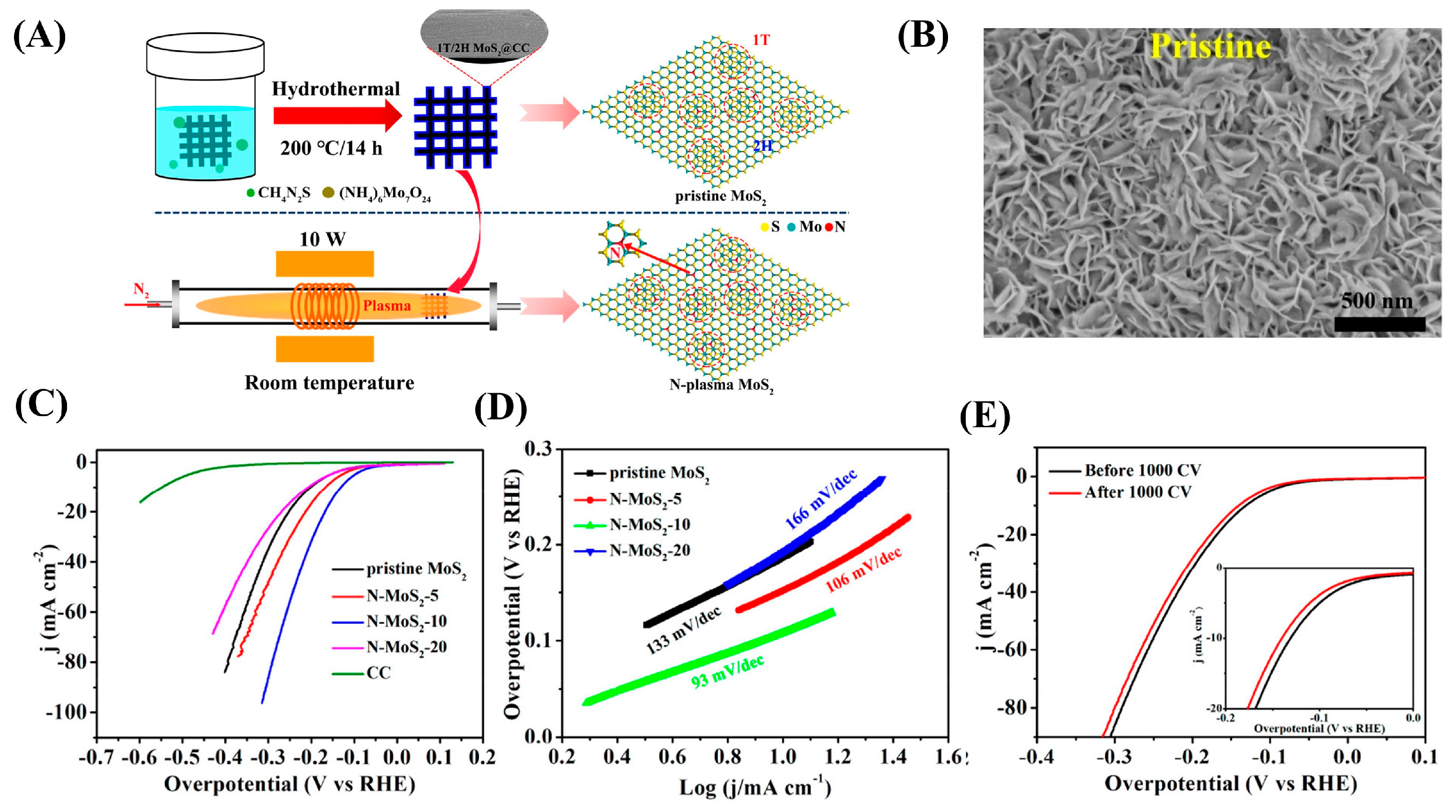
- Le, K.; Zhang, X.; Zhao, Q.; Liu, Y.; Yi, P.; Xu, S.; Liu, W. Controllably doping nitrogen into 1T/2H MoS2 heterostructure nanosheets for enhanced supercapacitive and electrocatalytic performance by low-power N2 plasma. ACS Appl. Mater. Interfaces 2021, 13, 44427–44439. [Google Scholar] [CrossRef]
- Feng, A.; Ding, S.; Liu, P.; Zu, Y.; Han, F.; Li, X.; Chen, Y. N, P co-doping triggered phase transition of MoS2 with enlarged interlayer spacing for efficient hydrogen evolution. New J. Chem. 2022, 46, 15693–15700. [Google Scholar] [CrossRef]
- Guo, T.; Lin, Y.; Chen, X.; Lu, J.; Zhao, X.; Yao, X.; Zhang, X. Metal-nonmetal atom co-doping engineered transition metal disulfide for highly efficient hydrogen evolution reaction. Int. J. Hydrogen Energy 2023, 48, 2990–2997. [Google Scholar] [CrossRef]
- Liu, M.; Zhu, J.; Liu, Y.; Gong, F.; Li, R.; Chen, H. Modulating the electronic structures of layer-expanded MoS2 nanoreactor via cobalt doping and carbon intercalation for enhanced electrocatalytic hydrogen evolution. Chem. Eng. J. 2022, 446, 137080. [Google Scholar] [CrossRef]
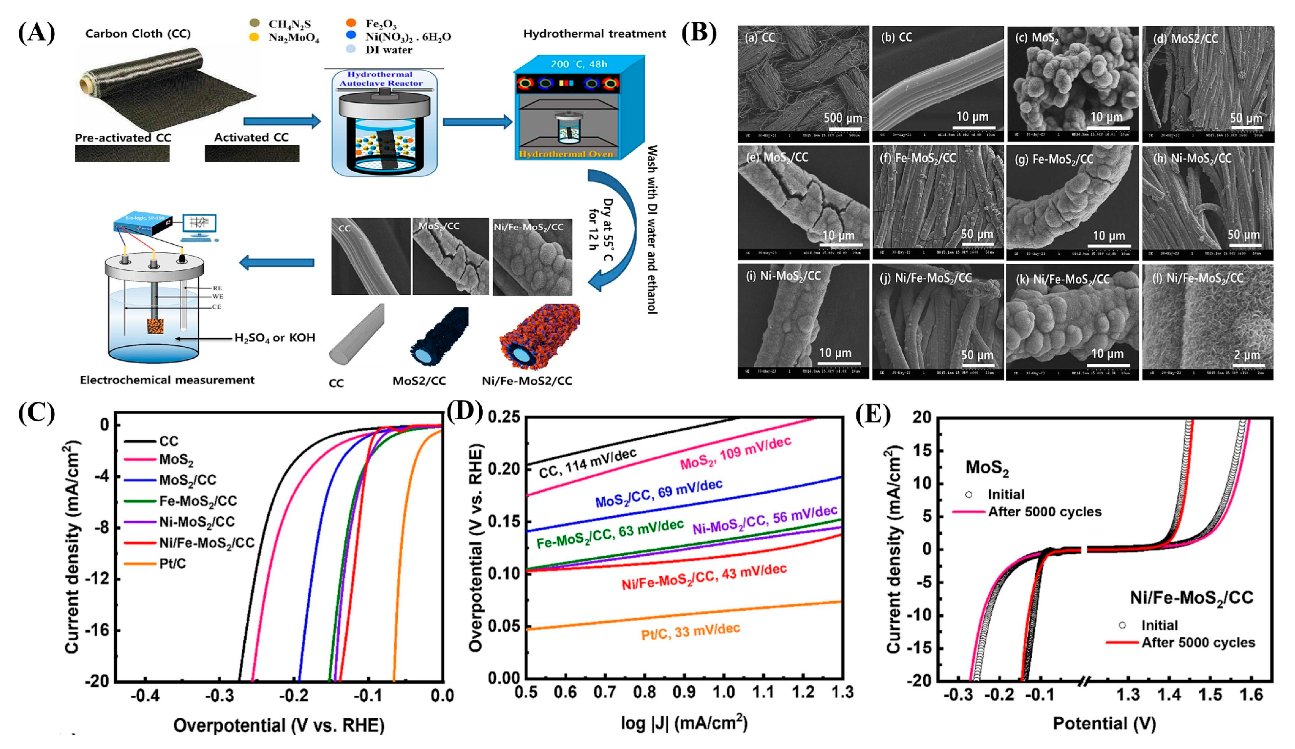
- Ghanashyam, G.; Jeong, H.K. Flower-shaped 1T/2H-phase molybdenum disulfide co-doped with nickel and iron grown on carbon cloth for enhanced water splitting. FlatChem 2024, 43, 100601. [Google Scholar] [CrossRef]
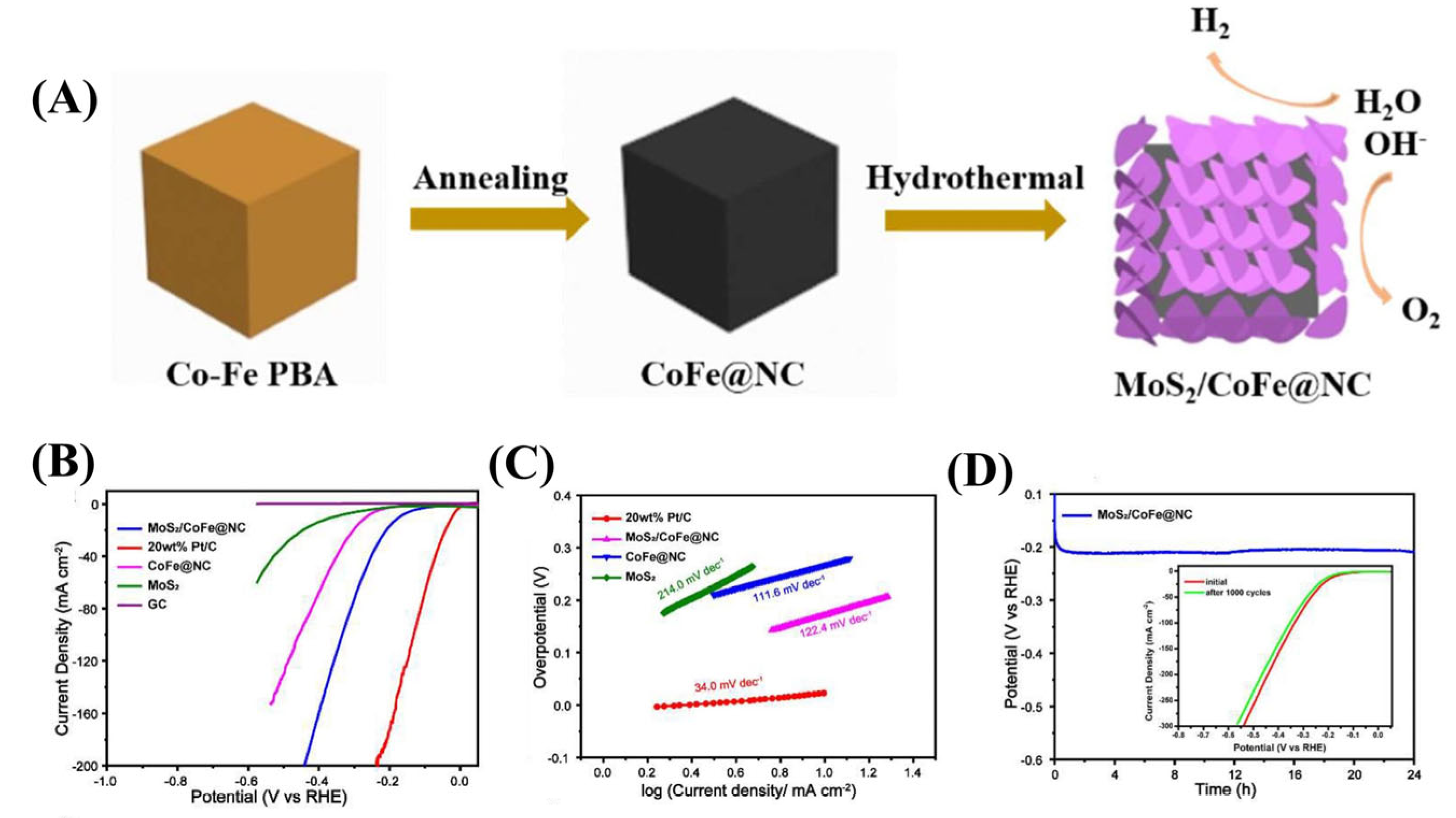
- Ma, W.; Li, W.; Zhang, H.; Wang, Y. N-doped carbon wrapped CoFe alloy nanoparticles with MoS2 nanosheets as electrocatalyst for hydrogen and oxygen evolution reactions. Int. J. Hydrogen Energy 2023, 48, 22032–22043. [Google Scholar] [CrossRef]


| Dopant | Catalyst | Catalyst Performance | Condition | Ref |
|---|---|---|---|---|
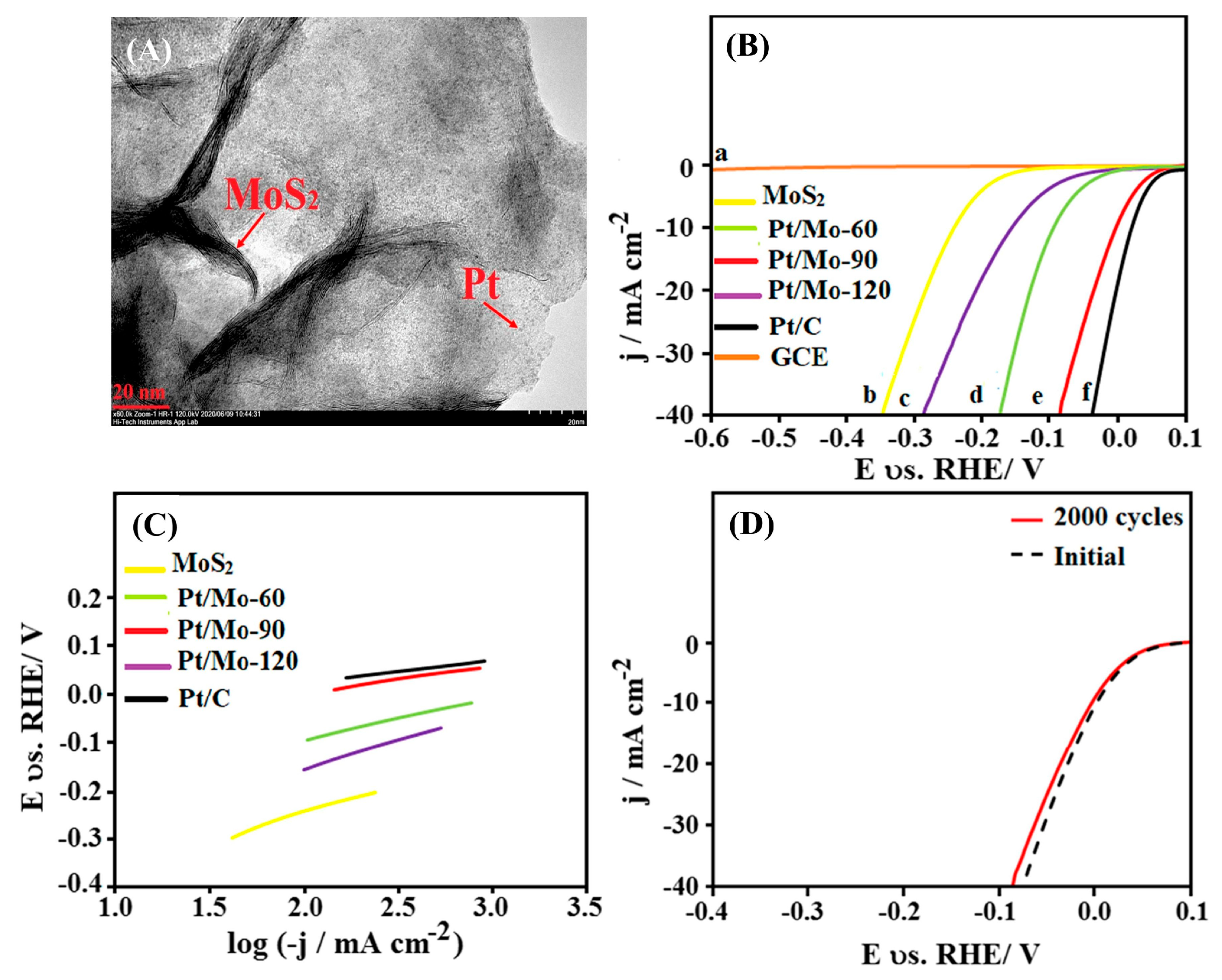
| Pt | Pt/MoS2-90 nanocomposite | Achieved η = −10 mV (@-10 mA cm−2) with Tafel slope 41 mV dec−1; retained 98% activity after 2000 CV cycles | 0.5 M H2SO4 | [83] |
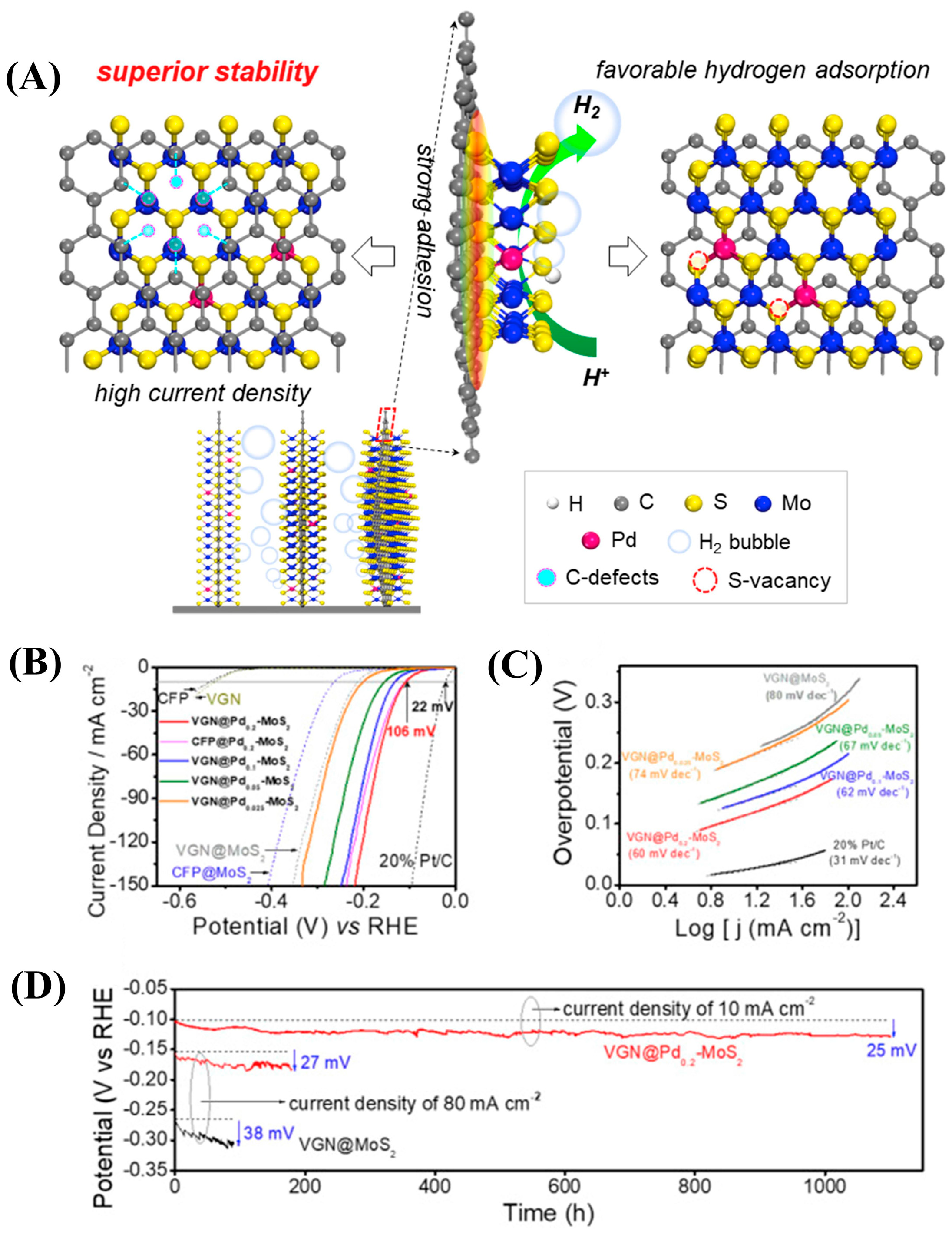
| Pd | 2 wt% Pd-MoS2 nanorods | Delivered η = 119 mV at 100 mA cm−2; no LSV shift after 3000 cycles | 0.5 M H2SO4 | [85] |
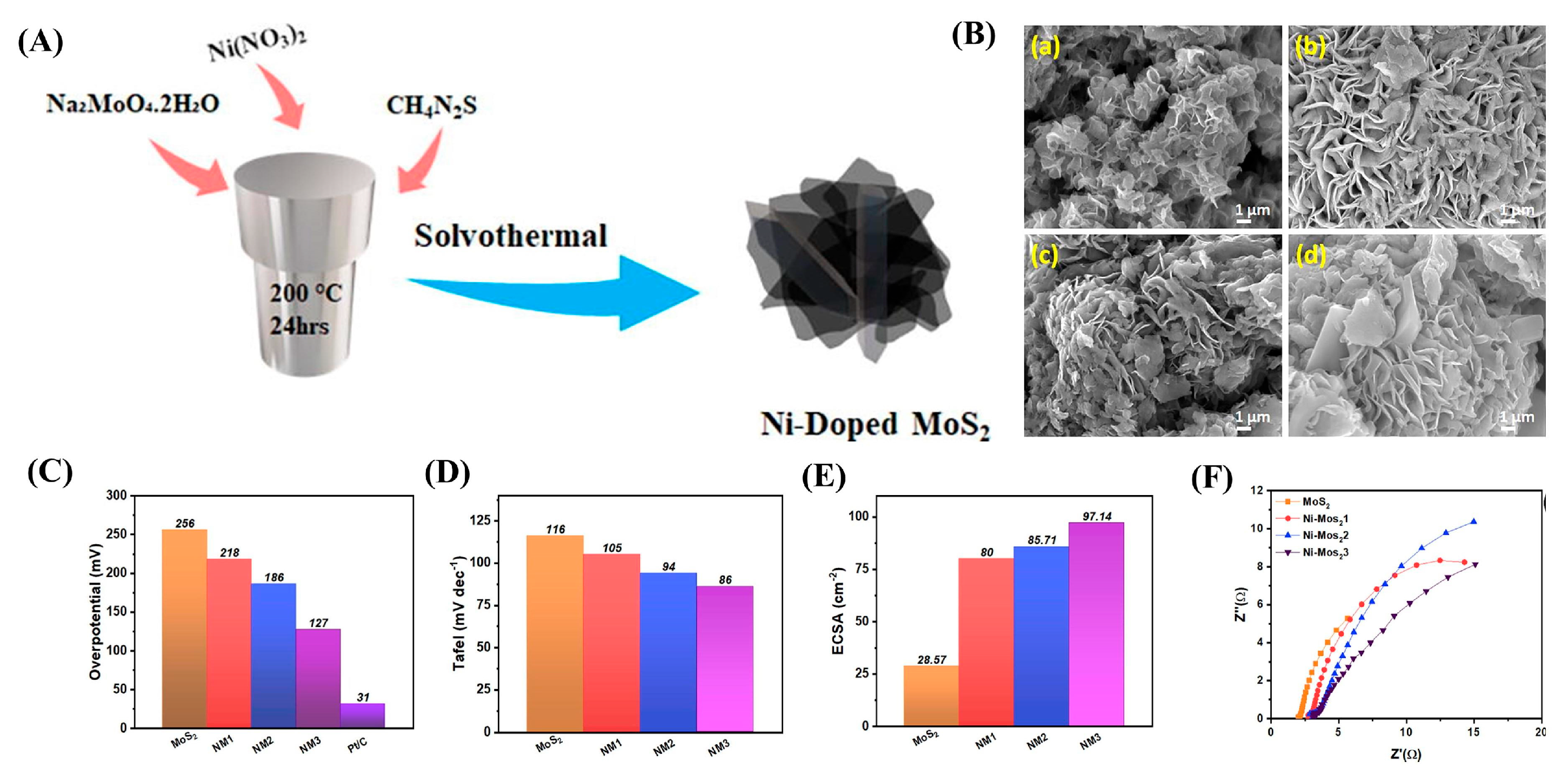
| Ni | NM3 (9% Ni-doped MoS2) | Exhibited η = 127 mV (@10 mA cm−2) with ECSA 97.14 mF cm−2; stability > 15 h via Volmer–Heyrovsky pathway | H2-saturated H2SO4 | [86] |
| Co | 0.2Co/MoS2@NPC composite | Demonstrated η = 139 mV (@10 mA cm−2) and ultra-low Rct (0.034 Ω); 93% stability after 1000 CV cycles | Acidic condition | [89] |
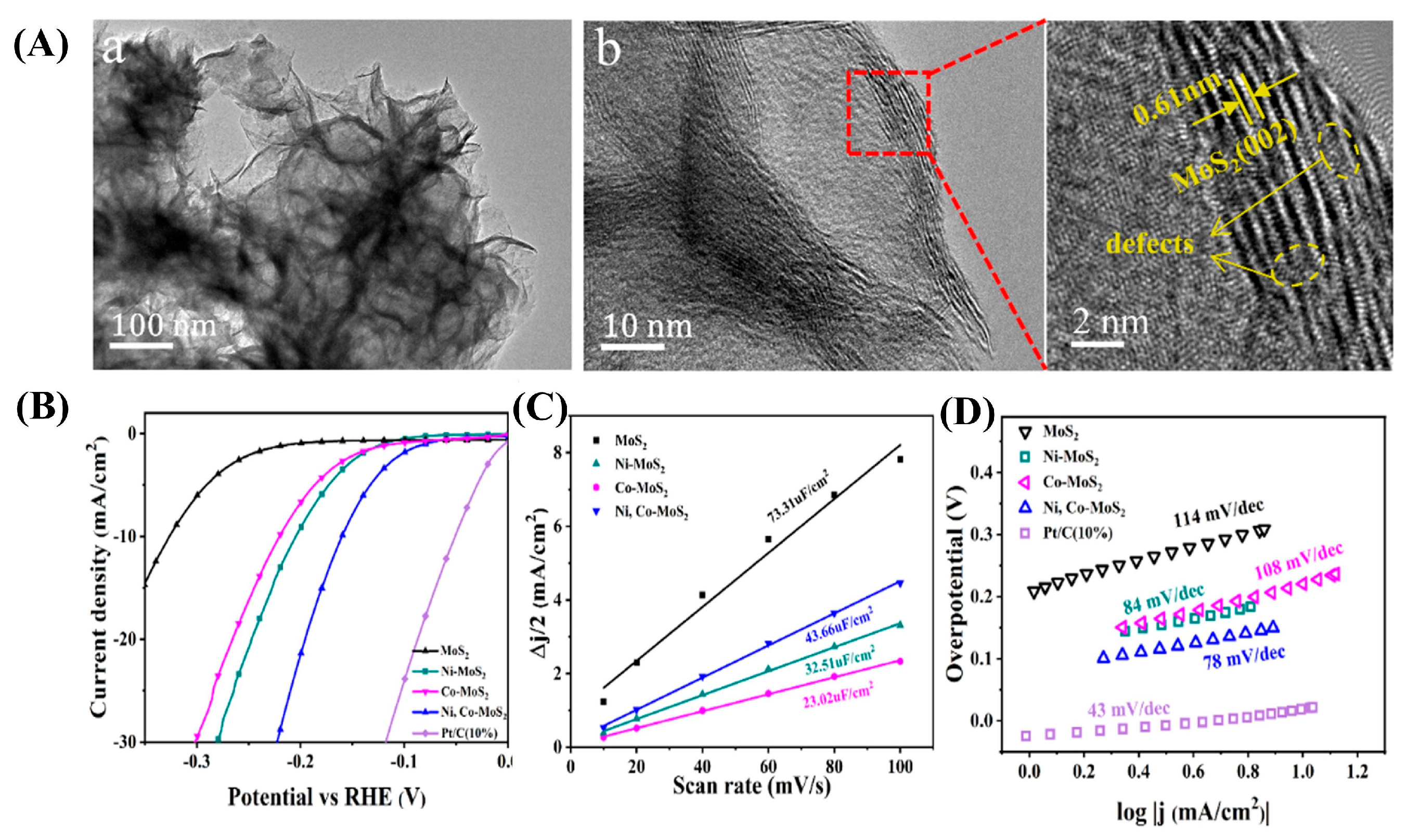
| Ni-Co | Bimetallic Ni, Co-MoS2 | Synergistic η = 160 mV (@10 mA cm−2); enhanced water dissociation (Ni) and H* adsorption (Co) | Alkaline solution | [91] |
| P | P-MoS2 nanospheres | Near-Pt/C performance: η = −219 mV (@10 mA cm−2); 99% current retention after 1000 CV cycles | Acidic environment | [93] |
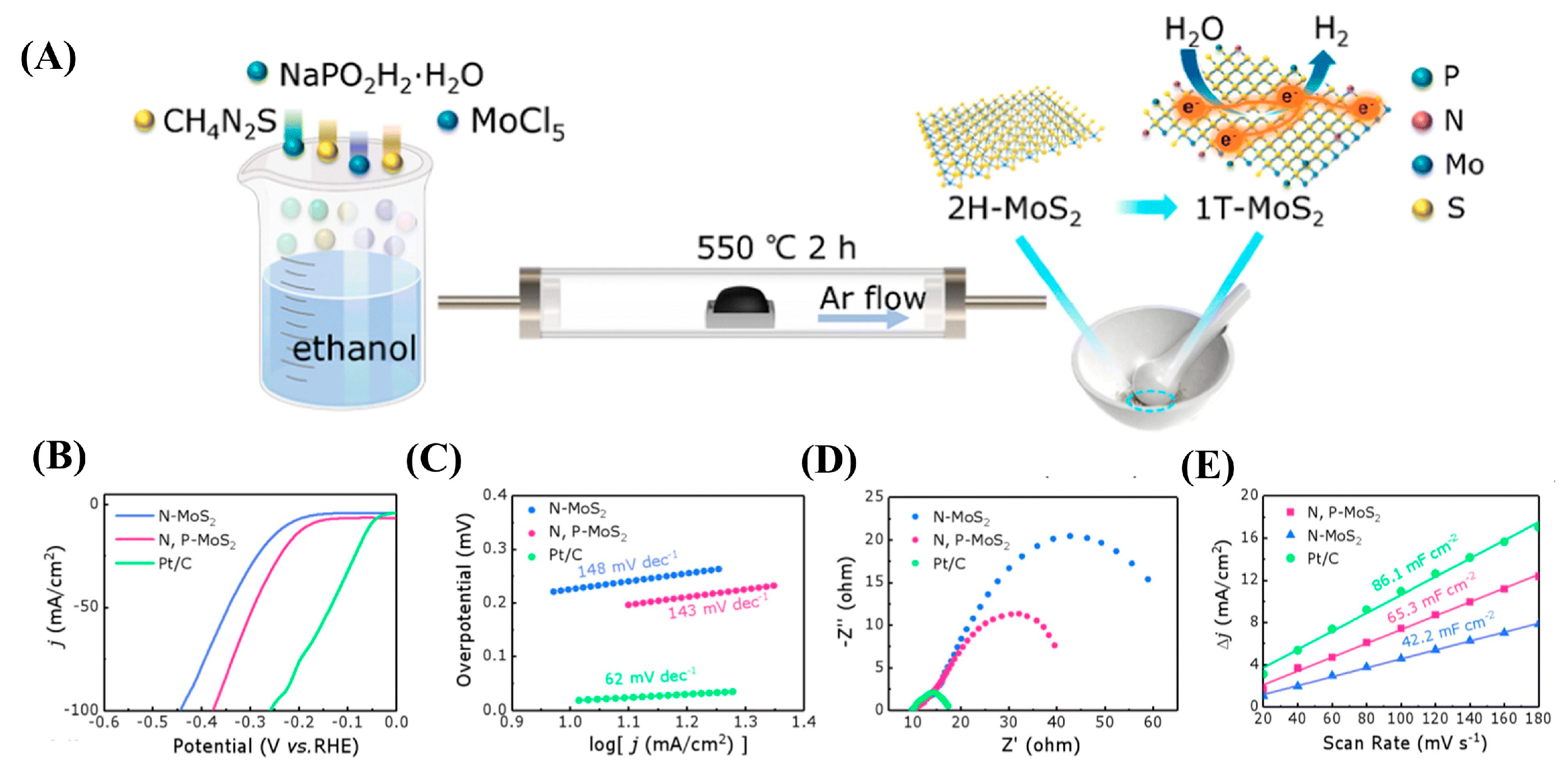
| N,P | N,P-MoS2 heterostructure | Expanded interlayer (0.65 nm); η = 179 mV (@10 mA cm−2); enhanced ECSA via S-vacancy engineering | Acidic medium | [95] |
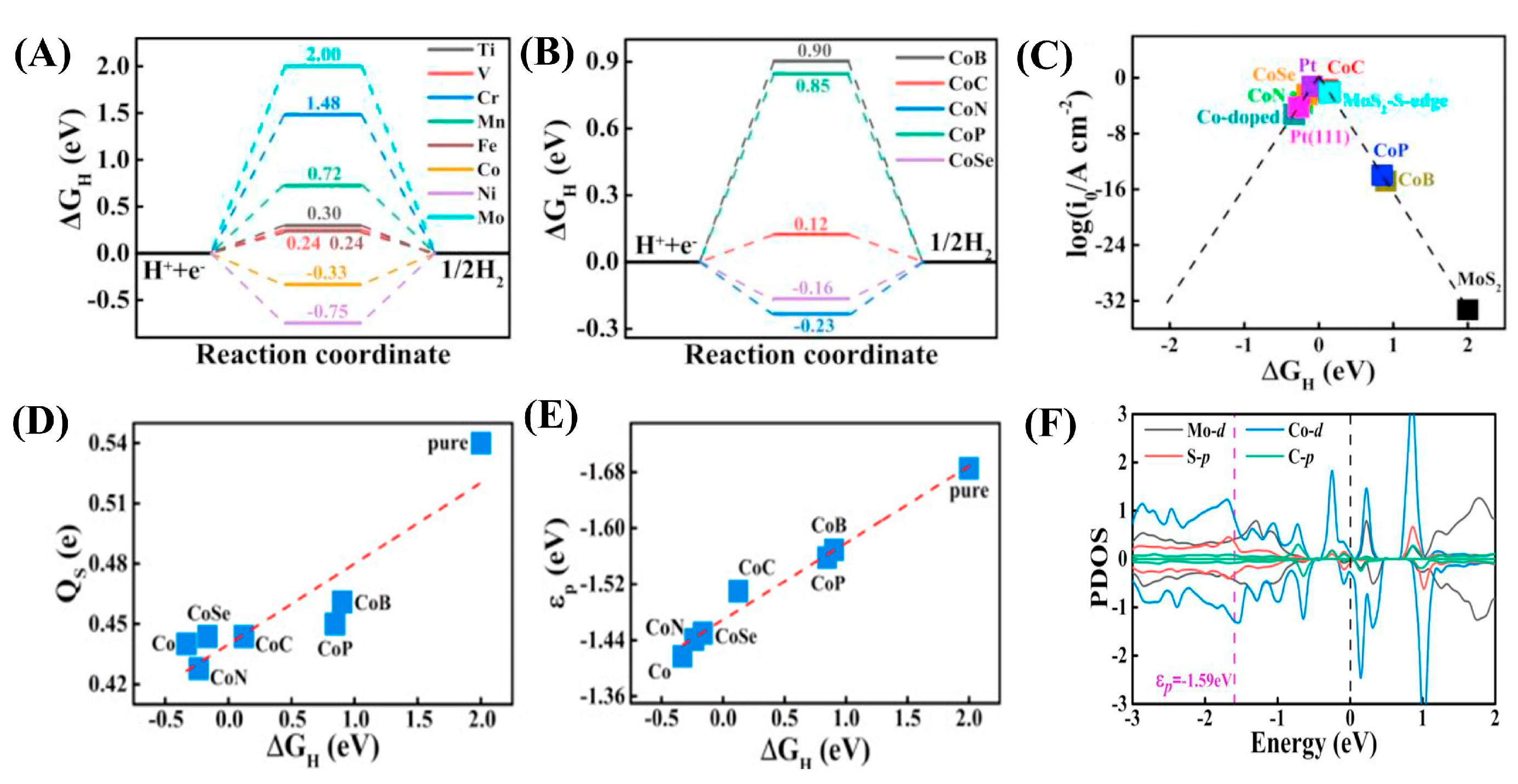
| Co-C | Co@MoS2/C microspheres | Superior activity: η = 70 mV (@10 mA cm−2); synergistic charge transfer via Co-C dual-anchoring | 0.5 M H2SO4 | [96] |
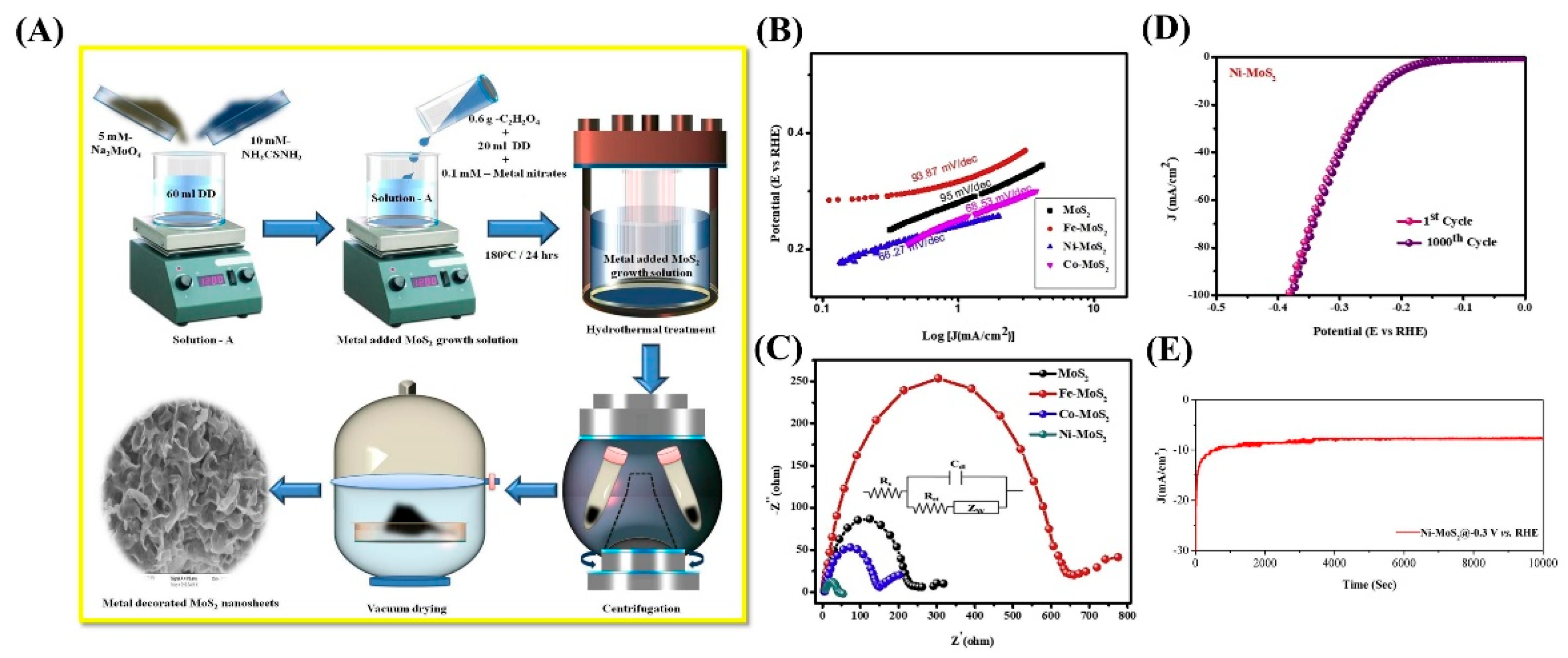
| Ni-Fe | Ni/Fe-MoS2/CC | Achieved η = −116 mV (@-10 mA cm−2); 1T phase-dominated (81%); stable in neutral media | pH 7 PBS | [98] |
Disclaimer/Publisher’s Note: The statements, opinions and data contained in all publications are solely those of the individual author(s) and contributor(s) and not of MDPI and/or the editor(s). MDPI and/or the editor(s) disclaim responsibility for any injury to people or property resulting from any ideas, methods, instructions or products referred to in the content. |
© 2025 by the authors. Licensee MDPI, Basel, Switzerland. This article is an open access article distributed under the terms and conditions of the Creative Commons Attribution (CC BY) license (https://creativecommons.org/licenses/by/4.0/).
Share and Cite
Liu, C.; Li, X.; Liu, Z.; Zhang, L.; Jiang, S.; Jiao, T. Recent Progress on High-Efficiency Hydrogen Evolution Electrocatalysis of Heteroatom-Doped MoS2: A Review. Catalysts 2025, 15, 520. https://doi.org/10.3390/catal15060520
Liu C, Li X, Liu Z, Zhang L, Jiang S, Jiao T. Recent Progress on High-Efficiency Hydrogen Evolution Electrocatalysis of Heteroatom-Doped MoS2: A Review. Catalysts. 2025; 15(6):520. https://doi.org/10.3390/catal15060520
Chicago/Turabian StyleLiu, Cihan, Xinyu Li, Zhiwei Liu, Lexin Zhang, Siyu Jiang, and Tifeng Jiao. 2025. "Recent Progress on High-Efficiency Hydrogen Evolution Electrocatalysis of Heteroatom-Doped MoS2: A Review" Catalysts 15, no. 6: 520. https://doi.org/10.3390/catal15060520
APA StyleLiu, C., Li, X., Liu, Z., Zhang, L., Jiang, S., & Jiao, T. (2025). Recent Progress on High-Efficiency Hydrogen Evolution Electrocatalysis of Heteroatom-Doped MoS2: A Review. Catalysts, 15(6), 520. https://doi.org/10.3390/catal15060520