Review

Evaluating Theoretical Approaches to Nitrogen-Doped Carbon Supports

1
Department of Pharmaceutical Sciences, Skaggs School of Pharmacy and Pharmaceutical Sciences, University of Colorado Anschutz Medical Campus, Aurora, CO 80045, USA
2
Department of Chemistry, Colorado School of Mines, Golden, CO 80401, USA
*
Author to whom correspondence should be addressed.
Catalysts 2025, 15(5), 473; https://doi.org/10.3390/catal15050473
Submission received: 21 March 2025 / Revised: 30 April 2025 / Accepted: 8 May 2025 / Published: 11 May 2025
(This article belongs to the Special Issue Single-Atom Catalysts: Current Trends, Challenges, and Prospects)

Abstract

:
Catalysis requires extrapolations from computational models to the catalytic activity observed under practical operating conditions, especially for single-atom catalysts, to be made. Thus, it is necessary to understand the fundamental interactions at an atomistic level to rationally design systems for targeted practical applications. With that in mind, the key aspects and parameterization of these model systems are especially important as they will heavily affect the validity of those extrapolations. Rigorously developed models and protocols with well-defined and understood metrics and interactions are reviewed to begin to provide an overview of the best theoretical practices for designing nitrogen-doped carbon supports.

Graphical Abstract

1. Introduction and Overview of Carbon Materials

Carbon materials play a crucial role in current and future technologies. It was only within the previous decades that certain allotropes of carbon, such as buckminsterfullerene, were discovered and carbon material research exploded [1,2]. It was even previously hypothesized that a two-dimensional “honeycomb” carbon sheet only existed theoretically, due to its foreseen thermodynamic unfavourability. Within the current century, graphene was first discovered [3,4].
There was a renaissance of carbon discoveries that followed through establishing its high tensile strength, electronic and thermal conductivity, flexibility, and capacity in demonstrating quantum phenomena. These properties have further extended in novelty through structural allotropes, seen recently in current attempts to synthesize “diamond-like” graphene bilayers, and practical implantations, through its usage in light detection and electrochemical sensing [5,6]. While many preliminary studies of these carbon materials were focused on synthesizing new allotropic forms, there has been a surge dedicated to transforming their novel properties into a broad spectrum of functionalities [1,2,3,4,5,6,7].
Graphene, seen as a basis for other dimensionalities of carbon (e.g., zero-dimensional fullerenes, one-dimensional nanotubes, and three-dimensional graphite), has sedimented a niche within electrochemistry as it acts as a high-surface-area support for next-generation carbon-based electrodes due to its broad modifiability and structural integrity under practical conditions, as well as its lower cost when compared to other metal or oxide support counterparts (Figure 1) [1,2,3,4,8,9]. The basis of the structure of these carbon materials is graphene. From the figure, it is shown how graphene can be transformed or combined into other macrostructures. These provide depth to possible carbon environments, but without feasible testing, they only present promising possibilities. Regardless, supports immobilize nanoparticle catalysts through strong metal–support interactions that also stabilize catalytic reactions. These carbon surfaces serve as a porous, stable, and conductive platform for the deposition, dispersion, and affixation of noble metal nanoparticles to effectively maximize the catalytic surface area. This advantageously has the benefits of both homogenous and heterogenous catalysis in that the support acts as a well-defined phase for chemical control but the catalysts can also be easily separable [3,9,10]. For example, platinum-based nanoparticles coupled with these carbon materials provide further flexibility in utilizing the excellent catalytic ability toward the oxygen reduction reaction (ORR) [11]. It was hypothesized that platinum has increased adsorption and dispersion to the graphene surface, creating an overall greater electrochemically active surface [3,9,12]. As a result, noble metal nanoparticles supported on graphene offer promising avenues for both fundamental and applied research geared towards better electrochemical systems. While carbon blacks and carbon nanotubes have been purposed for similar applications, graphene models a representative carbon surface allowing for the targeted study of specific metal nanoparticles supported on these materials [3,9].
Its active surface is also better retained when exposed to degradation and side-reactive oxidative species from the harsh fuel cell environments with high temperatures and acidity [9,12,13,14,15]. These advances are the beginning of the necessary groundwork for reaching industrially viable fuel cells while addressing noble metal scarcity and carbon material usability. However, the desired benchmarks for commercial use have yet to be achieved. This is because catalysts supported on graphene-based materials lack the necessary long-term durability, and thus, they require more investigation into their fundamental interactions with nanoparticles [16].
Most durability issues lie within the catalysts themselves. They degrade over time by either dissociating from the carbon support or forming agglomerations. In either case, the electrochemical surface area is decreased [15,16,17]. There exists an energetic tendency between different nanoclusters to agglomerate, which is initially thermodynamically countered by the carbon surface’s potential energy barriers preventing particle migration. Other degradation issues involve the oxidation of the catalysts or binding of reactive oxygen species that inactivate them [18]. The carbon support degrades through oxidative stress, hindering the interactions needed for catalyst–support durability [15,17,19]. These degradation mechanisms are actively investigated, particularly in platinum-based catalysts’ proton exchange membrane fuel cells, to further examine their impact on durability [15]. Increased graphitization stabilizes the support in resisting both degradation and catalyst dissolution because it decreases the available sites that are prone to carbon oxidation; however, this also results in fewer favorable available sites for metal deposition [15,20,21]. Consequently, further graphene modification is needed to preserve this durability while increasing binding interactions between the nanoparticle catalysts and the carbon support. The inclusion of a dopant within the carbon lattice is the route for this needed modification.
Doping introduces a reasonable contrast within a homogenous material in which the asymmetry then allows for novel properties. While there have been multiple heteroatoms that have been used as dopants, nitrogen was one of the first heteroatoms and has been studied the most. This is because a nitrogen atom is a comparable size to a carbon atom. As a result, the insertion of nitrogen atoms into the carbon lattice does not cause major structural disruptions. Nevertheless, nitrogen’s additional electron provides a difference in electronegativity in the carbon lattice, and its lone pairs participate in the π-cloud [8,10,12,15,22,23,24,25]. For nitrogen-doped graphene, the adjacent carbons to the nitrogen dopant generally become positively charged and open the graphene-limited band gap. Different doping methods and synthetic precursors introduce dopants into the materials in various ways, creating several possible types of functionalities or defects (this review will refer to nitrogen dopants within carbon materials as defects) [26]. Each introduction may induce unique electronic, dispersion, or geometric effects for future catalysts [27]. Interestingly, this modification of the support has some inspiration from biological active centers in which the dopants and catalysts resemble ligands chelated to a cofactor while the support acts as an extended molecular backbone [28].
Durability testing has been conducted with nitrogen-doped carbon materials where a doped anode was not only more durable than the undoped equivalent over time (by lessening metal dissolution), but also had a higher initial performance [21,29]. Systems with non-platinum metal catalysts supported on a nitrogen-doped graphene have been examined for possible electrocatalytic properties, while bimetallic nanoclusters maintain a higher durability with comparable performance. Platinum/palladium nanoclusters, compared to pure platinum nanoclusters, also interact beneficially with reactive species on the altered carbon surface [11,18]. This provides evidence that non-precious alternative metal catalysts may have worthwhile interactions with doped carbon supports. Consequentially, defects have been designed to stabilize single atom catalysts (SACs), reaching the upper bound of metal catalyst surface area utilization [8,30,31]. Further investigations into SACs have revealed an atomic understanding of the initial and prolonged catalyst interactions with a support. Overall, this heightened performance further extends the longevity of precious catalysts, offers promise in searching for non-precious replacements, and provides valuable holistic insights into fundamental catalyst–support interactions.
Studies have found that adding other heteroatoms with nitrogen also has beneficial results. However, one concern with current synthetic studies is that every novel combinatorial doping route always appears to improve electrocatalytic performance, regardless of the dopant combination. This concern was highlighted in a recent study that showed improved electrocatalytic activity when graphene was doped with chicken guano [32]. This article called for a fundamental chemical understanding of dopants within carbon supports for targeted experimental doping procedures. Density functional theory (DFT) calculations have been used to address this call as they have obtained insights, through methods such as evaluating the effects of dopants’ spin densities on the reactivity of nearby carbons, into the fundamental electronic driving forces behind the improvements observed with synergistic doping [26,33,34,35].
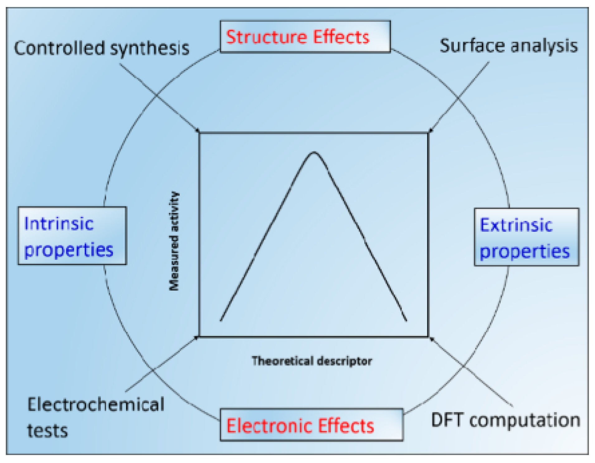
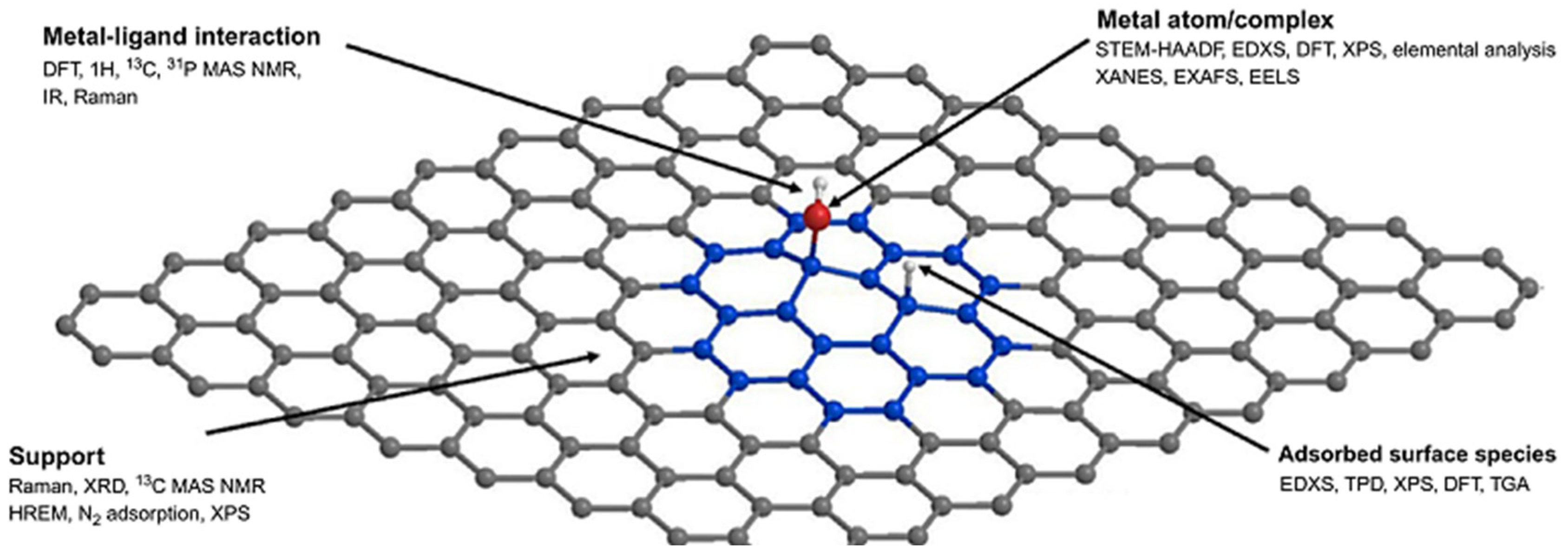
Nitrogen doping experimental efforts have proceeded with theoretical endeavors. This provides the best possible examination of both macroscopic and microscopic material properties in searching for future advancements (Figure 2 and Figure 3). Figure 2 presents a relationship between this review’s focused computational evaluation to physical correlates, presenting the holistic approach necessary to understand the fundamental chemistries to exploit novel material design. We see how computation can achieve electronic effects, alluding to certain chemical properties, but surface analysis is needed to confirm larger structural effects [36]. Figure 3 names the current methods used to export each aspect of the metal to carbon support structure. With the combined efforts, the structure to activity relationship can be determined and supported.
Theoretical studies may be categorized into bottom-up or top-down approaches, although they are not mutually exclusive. For bottom-up approaches, viable systems are narrowed down from extensive libraries of metal–defect combinations and energetic pathways are theorized with the wide range of computational abilities [38,39]. On the other hand, top-down approaches attempt to assist in understanding experimental data and characterization spectra, as they can often be limited in terms of studying the desired catalytic scaffold (the metal–defect–support structure) in isolation within the complex nature of these materials. These techniques display the average of the material’s surface, as experimental signatures may have a marginal or undistinguishable resolution, leading to unattributable functionalities, or provide limited characteristics, with the reminder that some techniques are just surface methods or are restricted by their limits of detection. Increased surface-sensitive methods and synthetic developments are still underway for these often largely heterogeneous materials [40,41,42]. DFT, in this approach, has been used to determine core-level shifts related to XPS binding energies to assist in modeling their spectra [41,43,44,45]. Trace metals from synthesis or low concentrated species can lie under XPS or XRD detection limits, falsifying characterization and observed electrocatalytic activity. Ye et al. showed that undetectable trace Mn (possibly from synthetic procedures) can shift the energetic barriers associated with ORR mechanistic pathways on graphene [46]. With theoretical work, different active sites (which will be defined as areas of the support where metal nanoparticles are interacting) have been explored in isolation to remedy this discrepancy by associating predicted electrochemical reaction metrics with experimental observations [37,41,47].
Top-down approaches can also provide synthetic validation. Thermodynamic metrics are relevant for catalytic scaffold formation energies within different material morphologies. Although kinetic barriers are overlooked, thermodynamic values provide probabilistic expectations for metal catalysts supported on nitrogen-doped materials [41]. Energies of formation based on nitrogen density and placement have been two central metrics in examining synthetically stable defect geometries of the graphene surface. While it has been experimentally seen that higher levels of implanted nitrogen tend to lead to smaller platinum nanoparticle sizes, increasingly higher nitrogen density does not provide a proportional return in these beneficial properties. Theoretical work has presented that nitrogen–nitrogen bonds undermine the overall stability of the material, rendering any improved effects from nitrogen doping ineffective, and thus, morphology also has a role in the resulting catalytic activity [22,48,49,50,51]. This suggests that nitrogen dopants may not exhibit cooperative properties when in close and random proximity. These studies show that researching the nitrogen-doped supports themselves is important when considering the support’s interactions with metal catalysts. Therefore, clear differentiation of the origins of observed beneficial effects require theoretical support [29,38,39,48,50,51,52,53,54,55,56,57,58]. However, many theoretical studies generally investigate systems which only contain a single pairing of a metal catalyst and a defect within graphene. While a handful of these studies serve as a top-down experimental supplement, it is challenging to extract non-specific fundamental interactions. Even though the ranges of different metals and defects have been analyzed, different computational parameters often make direct comparisons speculative and give rise to energetic discrepancies between similarly designed studies. Systematic studies of various metals with respect to one defect under identical parameters would provide a comparable basis to examine the principal interactions involved. By highlighting periodic trends through the inclusion of metal groups and periods, a deeper understanding of catalytically relevant or promising metals can be achieved that can also provide support in considerations of non-precious alternatives to expensive noble metal catalysts. Theoretical studies allow for this approach, given their unrestricted capabilities to explore vast arrays of systems.
Planewave-DFT is a conventional method for these theoretical studies due to its periodic treatment of the system by implementing periodic boundary conditions (PBCs). DFT on representative graphene-like truncated models (referred to as DFT models that do not apply PBCs) have been used in addressing similar investigations, such as oxygen reduction mechanisms and doped material stability [10,49,55]. Furthermore, molecular dynamics (MD) is another methodology that has been utilized in examining nitrogen-doped material stability and the energetics of doping nitrogen into the carbon lattice [49,59]. Nevertheless, this review will focus only on investigations using DFT methods. Both planewave-DFT and DFT have been used to model other carbon materials such as bi-/multilayered graphene/graphite, nanotubes, and nanoribbons [50,60,61]. Since graphene acts as a model system, it can also act as a basis for these carbon structures, but it does not cover all the intricacies from these other dimensionalities. These structures may be more representative of physical materials, but the computational consideration needed in matching their structural components may be expensive. Additionally, there has been experimental efforts in reducing the thickness of these materials to expose more defects/edge sites, alter the electronic structure, introduce novel defects, and create greater surface areas [26]. Computational modeling can provide even deeper insights into this matter. With this broad introduction that spans from carbon materials to catalysis to durability to dopants to the role of computational studies, this review intends to evaluate the extent of computational approaches, providing physical correlations balanced with fundamental knowledge on nitrogen-doped carbon materials and their support from metal catalysts.
Other reviews have examined the state of nitrogen-doped materials with metal catalysts in terms of synthesis, characterization, and electrochemical applications, both from experimental and theoretical perspectives. More specifically, significant focus have been directed towards applying these materials for relevant gas reduction reactions and examining single-atom electrocatalysts [42,62,63,64,65,66,67]. A recent review focused on the quantum chemical modeling of oxygen reduction reaction active sites of non-platinum group metal (PGM) catalysts and how theoretical results can be utilized to better understand these physical materials [41]. This review intends to extend this critical perspective onto other computational metrics and models..

2. Computational Methods for Studying Carbon Materials

We want to first preface this computational-focused approach to a review by establishing a basis in commonplace methods and metrics found in these associated studies for the reader. The authors would also like to mention that the field often uses the terms defect and dopant interchangeably. Herein, this review will also continue this usage, but will also acknowledge the distinction that dopant may refer to the heteroatom itself while the defect refers to the motif that is altered due to the heteroatom.

2.1. Density Function Theory

Density functional theory, commonly referred to as DFT, has sedimented its role in chemical research over the past decades in pure theoretical and semi-empirical work. Its prominence in predictions from first principles has provided accurate and expansive knowledge, furthering many chemical fields, as shown in Equation (1) [41]. While DFT solves the tremendous computational cost of Columbic considerations, the computational throughput needed to calculate the electron density of a material can be infinitely more expensive. The sheer number of electrons in a material far surpasses any direct all-electron numerical approach, although it should be mentioned that DFT methods have been improved for the viable treatment of larger, more complex systems [68]. It is known that periodicity, due to the crystal nature of materials, can be exploited to determine the electron density and material properties. Even if the material is quasi-periodic or unsymmetrical, a computational model can be designed to examine it. These models utilize periodic boundary conditions (PBCs) for this exploitation. A translation that is proportional to the lattice vectors of the material’s corresponding crystal structure will find the same electronic potential between the originating and ending locations of that translation. Bloch’s theorem states that the wavefunction for Schrödinger’s equation can be expressed as planewaves tailored to the periodicity of the system [69]. These methods, when applied to materials, are conventionally referred to as planewave-DFT. With PBC, a unit cell is established to generally encompass the first Brillouin zone, although super cells may be used which enclose additional space, surpassing the first Brillouin zone with respect to the lattice vectors. From Bloch’s theorem and PBCs, the electron density can be known and used to obtain ground state energies and related measurements of the unit cell from which material properties can be derived (Equations (2) and (3) detail Bloch’s theorems, where u is any periodic function corresponding to the lattice indexed by k , which is a vector describing the crystal momentum; r is a position within the unit cell; R is a translation; and e i r summates into any phase factor. Equation (2) demonstrates translation symmetry while Equation (3) demonstrates the expression for the wavefunctions used.) [69].
H ^ ψ = E ψ
u k r + R k = u k r
ψ k r = e i k r u k ( r )
u k r = G c G k e i G r
E c u t   1 2 G 2
There are two parameters that are conventionally selected with convergence tests. The first is referred to as the kinetic cutoff energy (Equations (4) and (5) detail the kinetic cutoff energy E c u t , where   c are the coefficients of the series and G is any vector in the defined space). Since u is periodic, it is expressed as a Fourier series in which each basis function represents a planewave, moving in the space perpendicular to vector G . G can be any vector of the space in which the coefficients of the series are inversely proportional to the magnitude of G . Thus, G vectors with larger values have correspondingly smaller weighted coefficients that contribute relatively less to the overall expression. Given the computational capabilities, all G vectors do not need to be considered for practical accuracy. By associating these planewaves based on G to a kinetic energy value, a cutoff energy can be established in which only the planewaves less than or equal to that value are included in basis functions for the series summation (Equations (4) and (5)). This threshold is systematically selected by increasing the kinetic energy cutoff while checking for the convergence of the ground state energy to a defined accuracy, as higher cutoffs values are more computationally expensive, when considering diminishing returns.
The other parameter is k-point sampling. K-point sampling involves collecting vectors from the unit cell’s origin to r and considering the electronic states within the variation in r, like in DFT, where all electron contributions of a molecule are summated in determining the ground state energy. There is an infinite amount of r , surpassing any analytical approach. However, u k r depends weakly on k , making it sufficient to use a small finite number of k-points [69]. It is possible to then choose a representative number of varied k-points rationally to consider the electronic states simply and accurately. Furthermore, materials retain various symmetries, seen in their unit cells, in which k-points sampled can be further reduced due to their uniqueness. Thus, it is valid to deliberately choose k-points within an irreducible region of a Brillouin zone. It should be mentioned that some symmetries are also dependent on the Γ-point, or the Γ-point itself is physically important. K-point sampling correlates directly to computational costs, but there are various exploitations, such as the symmetries mentioned earlier, in reducing the number of k-points needed for an accurate electronic description of the material.
A modern method of choosing k-points, defined by Monkhorst and Pack, is to overlay a three-dimensional equidistance grid defined by three integers over the unit cell, in which only then are the irreducible k-points used (Figure 4) [69]. This method offers a relatively simple numerical approach to scaling k-points for convergence. When considering non-three-dimensional carbon supports, such as graphene or nanoribbons, one or two of the grid-defining integers can be set to one, respectively, to advantageously sample the support, given its dimensionality. Other methods have been and are used for k-point sampling. However, further discussion exceeds the scope of this review.
While those two parameters are used the most to check for convergence, there are others that have been factored into model parameterization, and it should be noted that convergence is model and system dependent. These parameters are computationally bounded, such as defining how the self-consistency cycle is approached in solving the Schrödinger equation. Another example is electron smearing, which defines the energy gap around the Fermi level and allows for fractional electronic occupation to assist with self-consistent convergence. Basiuk found that commonly used smearing values obtained significantly different results when compared to relatively lower values in certain systems [70]. Another significant parameter, specific to planewave-DFT, that encapsulates all these other parameters indirectly is the unit cell. The unit cell size varies the lattice vectors and space sampled. However, k-point sampling may not change if the unit cell is multiplied in a manner that retains original symmetries. For the systems explored in this review, defects and nanoparticles reduce the number of symmetries a unit cell may have, making the choice of unit cell more prominent.
From a physical perspective, the unit cell can be extrapolated to a material’s morphology. With PBC, it can be visualized that the unit cell is repeated indefinitely in correspondence to the lattice vectors. Therefore, in these nitrogen-doped systems with supported nanoparticles, it is essential to actively design a unit cell that has a physical correlation. In addition to dopants, there are vacancies in the carbon lattice caused by the doping process. While studying the electronic nature of defects and vacancies, it is equally important to design unit cells that have a synthetically viable morphology. The electronic information gained may be limited if the material corresponding to the unit cell is physically unstable. Similarly, a large ratio of nitrogen defects to carbon atoms alters the support from a carbon support to a carbon–nitride one. While there is no defined threshold, the repulsion from the amount of resulting lone pairs provides a sense of such a level [51]. The percentage of nitrogen in the unit cell should reflect that of realistic doped materials. Matching the doping percentage to targeted functionalization is the goal, which is investigated through these theoretical methods. Through both direct synthetic and post-treatment methods, the maximum doping percentage was found to be about 10% on average [22]. Additionally, with the nitrogen morphology, the size of the model nanoparticle in the unit cell should be physically significant. Again, the representation of a nanoparticle on a support at a direct scale far exceeds computational limits. Since the surface chemistry of these nanoparticles on the support is a focus, the carbon material’s surface is often represented as graphene. This is accomplished by creating a vacuum region in the direction of the axis perpendicular to the surface since the PBCs are still retained on each axis and this separation negates any interactions between graphene surfaces. This vacuum space manipulation is how other carbon dimensionalities can be studied. With a single surface layer, nuances are introduced for defects and nanoparticles as opposed to the bulk phase, but this reduction is valid, given the locality and the scale of chemical phenomena. Some approaches have been made to remedy bulk considerations. One study introduced increasing layers of solvation on a single side of graphene before moving to both sides, and ultimately increased the layers of graphene up to three [71].
Nanoparticles can also be simplified into SACs or nanoclusters, causing an overlap in research between nanoparticle supports and atomically dispersed catalysts. This treatment still provides valuable insights into nanoparticles’ macroscopic properties and may even be somewhat physically identical as it has been shown that sub-nanometer nanoclusters are being pursued due to their higher catalytic activity than their larger counterparts [26,68,72]. One goal for theoretical work in this field is to best understand the size gap between models and reality. The ratio of the nanoparticle’s size to the unit cell is also relevant when considering the relative size of metal to carbon/nitrogen atoms. It is possible to eclipse the unit cell or have a nanoparticle to support ratio that is not physically representative as the density of nanoparticles also affects the morphological considerations. Other computational approaches have been performed to explore material stability during and post-doping [49,59]. For this review, studies that utilize DFT as their primary computational method will be discussed.

2.2. Theoretical Metrics

DFT calculations can be partitioned into how they provide an understanding into certain physical aspects of the metal–support scaffold (Figure 3, vide supra, and Table 1). First, they can contribute to examining the doped support by looking at its relative overall stability among different possible defect/vacancy combinations. Second, they largely examine the interactions between the metal nanoparticles and the support. There are vast possibilities in the ways the two entities may interact, and thus, the appropriate definitions of those interactions must be defined for valid physical interpretation. Third, they gauge the scaffold’s interactions with reactants and possible catalytic pathways. This review will discuss studies with these metrics, but beforehand, a non-comprehensive overview of these metrics will be provided.

2.2.1. Support Structure

Studies have been performed exploring nitrogen-doped carbon supports, comparing the edge-to-in-plane and surface-to-bulk sites, as edge sites might even present different chemical properties [73]. Although the bulk may not be of high interest, as compared to the surface, the porosity is still relevant when considering molecular diffusion to internal defects. The most used metrics are Gibbs free formation energies, describing the thermodynamic favorability of forming these nitrogen defects and vacancies within a carbon material. Simply, they are the difference in Gibbs free energy between an initial and final state, usually before and after doping, respectively. Different studies have introduced additional enthalpic and entropic terms to this formulation to better align with certain physical assumptions. These values may decipher which defects are expected out of different synthetic routes by considering these formation energies against the method of implementation (whether it be precursors forming bonds or nitrogen atoms ejecting out carbon atoms), possible activation barriers, and reaction temperatures [2].
Other energies extracted from the doped support can relate to spectroscopic peaks, such as core-level binding energy shifts for the XPS spectra. By examining small energetic differences between spectroscopic signatures at a theoretical level, otherwise indistinguishable at an experimental spectrum, reference peaks may be identified for comparison and experimental shifts. These energies can be used to approach discrepancies between material activity and characterization. Ambiguity exists in correlating observed structures to catalytic activity. By attributing catalytic activity to a prominent species, moderate activity per species site is implied. On the other hand, the attribution of catalytic activity to a lesser abundant species would imply a much higher activity per site, given the relative speciation. It is also possible that both species are catalytically active. DFT assists by displaying the possible effects of structural composition that are under the limits of detection, as well as the relative activity between sites. Associated energies of both of these cases can be extracted and compared in terms of their physical characterization. Different relative ratios of structural support characteristics may offer discernable energetic signatures.

2.2.2. Catalyst–Support Interactions

The understanding and strengthening of these core interactions are areas of pursuit for these materials. Physically, these interactions appear to be responsible for durability increases shown in nanoparticles on pure carbon supports compared to nitrogen-doped carbon supports. The goal is to define these computational metrics so that they may be relayed into a formal understanding of these interactions. One conventional way this has been performed is through “volcano plots”, where the catalytic activity or related response is measured as a function of one of these possible metrics. The curve the plot forms is volcano-like, where the apex represents an ideal system, according to the Sabatier principle [41]. Certain specific metals or defects can be overlaid on the plot to see which systems have the best performance in a certain regard, relative to each other, as well as to gauge how well a computational metric correlates with an experimental observation. Changes in density analysis have also been used to further gauge these interactions, such as density of states or Bader charge analyses [62]. Theoretical studies have shown that these interactions increase from an undoped to a doped support, although there are subtleties in their values, according to their metrics used. The following section outlines some of these metrics (metrics may be referred to with different names across the field).
  • Adsorption energy
Adsorption energy (also referred to as binding energy) is a common metric in exploring metal–support interactions, as it serves an important role in surface chemistry [74]. For computational models, adsorption energy may be defined as the change in potential energy between the nanoparticle and the support if the nanoparticle were instantaneously placed on the surface of the support. Generally, this is calculated by finding the difference in Gibbs free energy between the two entities at infinite separation versus interacting proximity. It can also be seen visually with the lengths of atomic separations or conformation changes. Although the metric does not dissect the nature of such interactions, it provides the general strength of the overall interactions. Some studies have focused on the overlap of the nanoparticles’ d-orbitals with those of the surface in attempting to hypothesize their nature [68]. In increasing the strength of these interactions, the adsorption energies would correspondingly increase and most likely be physically expressed as increased durability.
2.
Ripening energy
Ripening energy broadly encompasses nanoparticle size changes. These different energies define how the nanoparticle may disperse or grow from a solution or neighboring nanoparticles. Gao et al. defined cohesive energy as a metric in determining whether the atoms in a nanocluster will be reunited as atoms or become more stable as a cluster. Li et al. compared iron’s cohesive energy to iron’s adsorption energy within a nitrogen-doped vacancy and discovered that the iron would be bound strongly to the defect site but would still preferentially have stronger binding to the iron bulk source [38,75]. Furthermore, there are various pathways in modeling particle growth computationally: adsorption energies may be taken by optimizing increasing nanoparticle sizes on the support or optimizing the resulting nanoparticles after each addition of an atom, upon seeing any expressions of cooperativity or geometric influences. Both offer interesting and different possible approaches in representing these phenomena. Future studies may extract the best predictive model. Different energetic descriptions may be formulated to describe the tendency of certain particle growth or dispersion events. This metric is used to assist in understanding particle dispersity upon the support.
3.
Migration energy
Migration energy refers to the nanoparticle’s susceptibility to move across and away from the support. It can be defined by the differences in adsorption energies for the nanoparticle across the surface. Nakada et al. claimed that 0.5 eV was the threshold for atomic migration at room temperature, meaning that any adsorption energy values beneath that would be overridden with kinetic energy from room temperature [74]. It extends adsorption energies into a potential energy mapping of the support, examining favorable sites for nucleation relative to the material and highlighting possible pathways in which the nanoparticle may move across the surface from unfavorable adsorption locations. A mapping would display areas with weak or unfavorable interactions and energetic barriers, forming potential energy wells. This portrays an atomic representation of nanoparticles’ movement in either aggregating or dissolving from the support.

2.2.3. Electrocatalytic Energies

Electrocatalytic energies relate the catalytic scaffolds’ interactions with reactants to provide a measure of the catalytic ability for current reactions of interest. In the context of graphene and nanoparticle catalysts, catalytic reactions can include gas reductions in completing feedstock cycles. Densities of states or electronic mappings are examined to first gauge the scaffold’s affinity to reactants. The Sabatier principle once again is relevant, as there is an optimal range for this affinity, as too weak of an interaction poses no adsorption while too strong of one may lead to no dissociation, rendering the scaffold inactive; this alludes to selectivity considerations [72]. Theoretical pathways have been hypothesized based on chemical intuition to differentiate the thermodynamically favored pathways for these redox chemical reactions. Furthermore, kinetics have been elucidated through reaction barriers, reaction energies, and associated entropies; however, some extrapolations have solely been made from thermodynamic values, where they may or may not have entropic and enthalpic considerations [51,68]. The stability and activity of the catalyst–support with reactants are heavily physically explored; these theoretical investigations pose feedback modifications. These structures referenced here are often referred to as active sites that spread across the support.

3. Role and Computational Representations of Nitrogen-Doped Carbon Materials with Design Challenges

With an understanding of how carbon materials with catalysts are evaluated, this review will present how the addition of nitrogen to the supports adds nuance to their computational design as that plays a significant role in how the field approaches studying them. Furthermore, it will showcase how the designs of these supports, given the variety between studies, propagate into nuanced results. This section will be summarized in Table 2.

3.1. Defects

The focus of this section will be on the supports themselves, but it will include studies that present evidence of their catalytic activity. There are various defects formed due to nitrogen doping; however, three types of defects specifically have been a focal point, usually depicted on nitrogen-doped graphene (Figure 5). The three focal point defects are referred to as graphitic, pyridinic, and pyrrolic [61]. Starting with graphitic, these defects are a result of the direct replacement of a carbon atom with nitrogen. The nitrogen atom seemingly falls under the same bonding and hybridization as its predecessor. Presently, there is debate whether nitrogen’s extra electron is intact within a lone pair or contributes to the material’s π network. This may be dependent on the location of the defect, given its possible geometric flexibility at a valley versus a center, as shown in Figure 5. Another discrepancy with graphitic defects is that they are interchangeably referred to as quaternary defects, while in some other studies, they are referred to as another entirely discrete defect (Figure 5). Wood et al. established a difference between the two names by redefining quaternary defects as a substituted carbon with an sp3 hybridized nitrogen, due to its positive charge, as opposed to a graphitic one [22]. Due to this hybridization, Dai et al. stated that the defect is distinguished by its nonplanarity [2]. Artyushkova et al. further suggested that this defect has its own spectroscopic signature, separate from graphitic defects, due to its edge positioning and representation of a protonated pyridinic defect instead, given its shared geometry and charge [76]. It is possible that this difference has a minimal effect on chemical distinctions, and thus, clarification may not be warranted, but a study addressing that could provide novel implications. For this review, the defect mentioned will be specifically described.
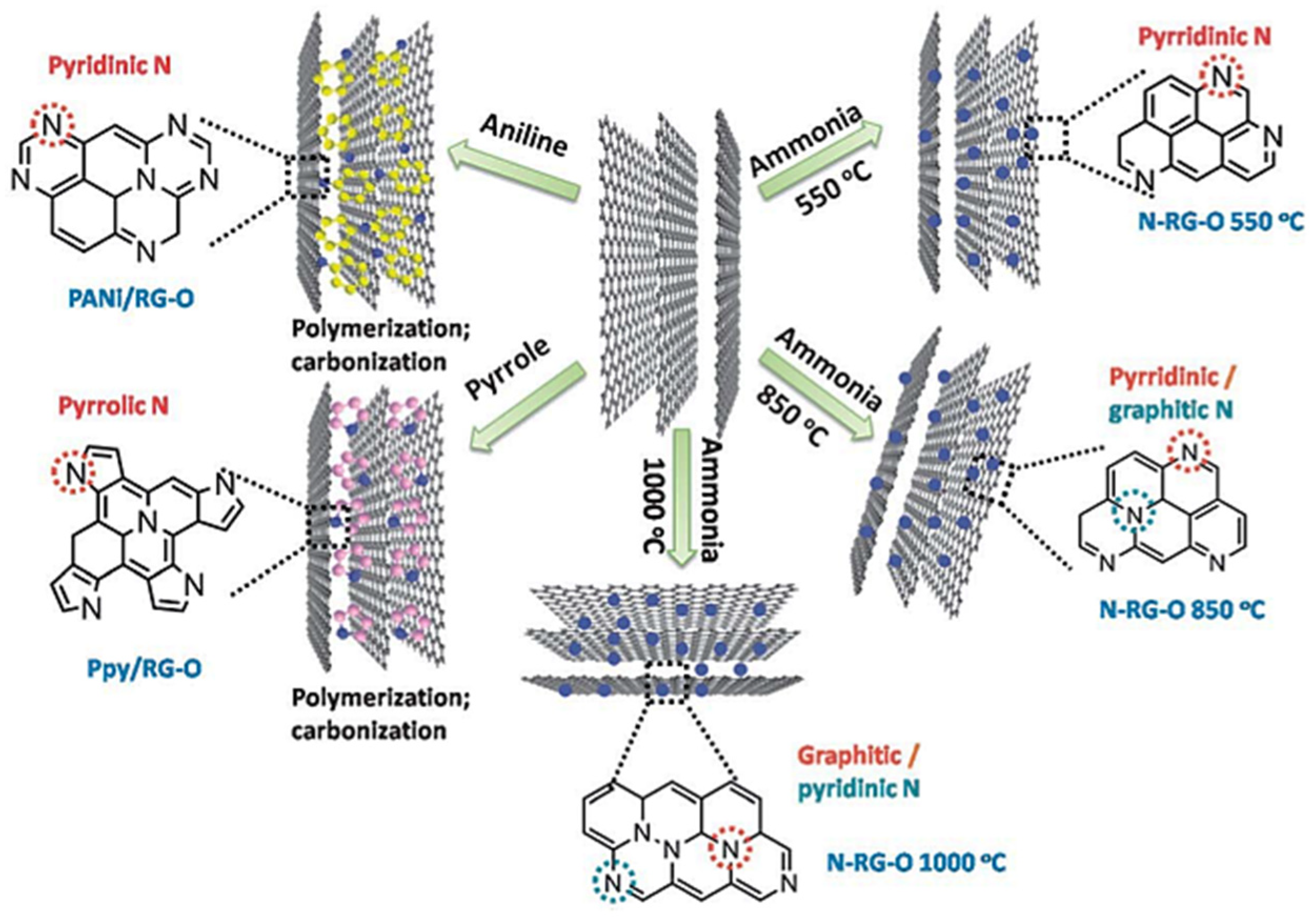
The pyridinic and pyrrolic defects represent pyridine and pyrrole, respectively (Figure 5). Their defining characteristic is that they contain a lone pair that usually participates in catalyst coordination but can be consumed through hydrogenation or oxidation, altering their chemical reactivity. These two defects are embedded at either the material’s edges or at vacancy sites, respectively, in a hexagonal or pentagonal geometry. If placed directly within the graphene, pentagonal cycles within the graphene form or molecular optimization is abstained [77]. The pyridinic nitrogen atom is sp2 hybridized and the pyrrolic nitrogen is sp3 hybridized, contributing their p electrons to the π system [78]. At vacancy sites, these defects are usually represented as clusters, rather than a singular defect, and are referred to as active sites when coordinated to metal, which is synthetically viable. Figure 6 displays some examples of this control as low temperature in situ doping methods seem to favor the formation of pyridinic/pyrrolic defects while high-temperature post-treatment methods favor graphitic ones. Precursors may also dictate the likelihood of certain defects, along with other methods in development [26,42,65,79]. Nitrogen content can also be controlled through these methods, which allows for microscopic equivalent treatment in computational models.
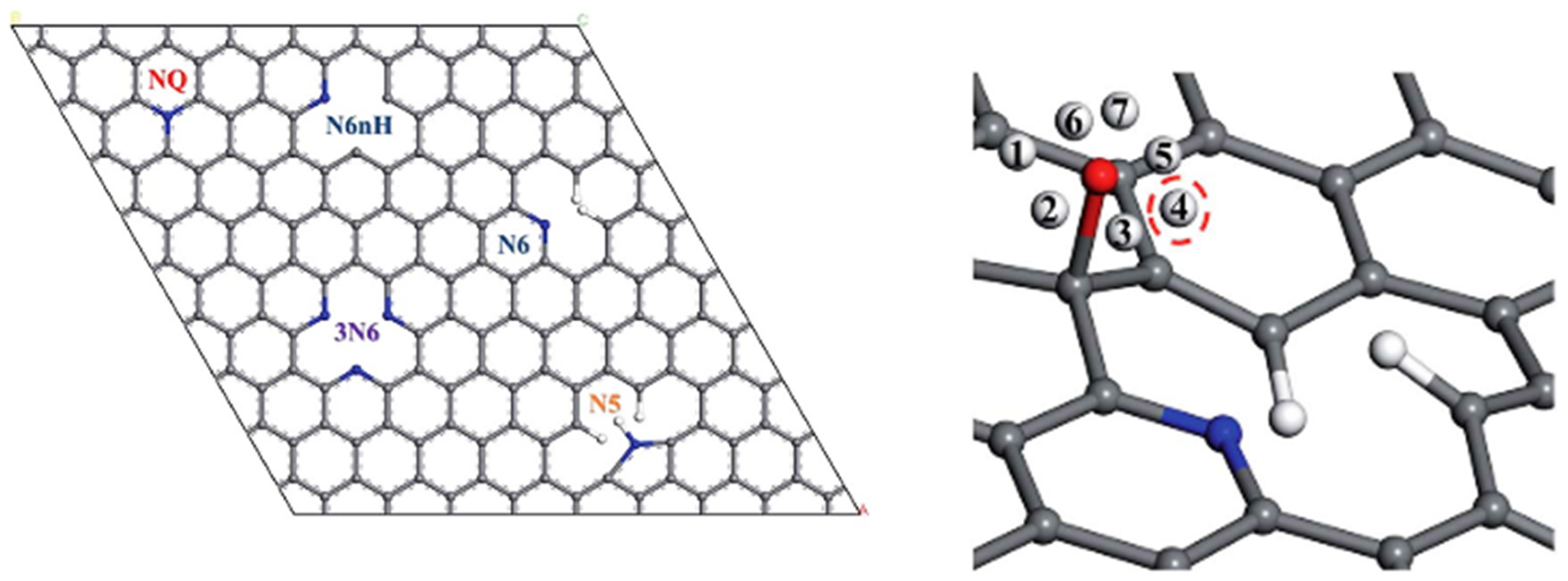
Tai and Chang noted that there are a lack of systematic studies regarding these defects. They modeled the three defects and treated the placement of the pyridinic and pyrrolic defects at the edge uniquely. The quaternary defect (NQ) remained a substitution but the pyridinic (N6) and the pyrrolic (N5) were inserted next to a vacancy where the other carbon atoms affected by the vacant carbon were hydrogenated to simulate an edge; the other two defects were N6nH, which is N6 without the vacancy hydrogenation, and 3N6, which is three pyridinic defects in a vacancy (Figure 7) [80]. This edge modeling of the pyridinic and pyrrolic defects allowed for a direct systematic comparison with the graphitic one as opposed to designing a different model with a discrete edge. The hydrogenated carbon also addressed the electronic nature of the carbon affected by a vacancy. As a side note, Li et al. suggested that these carbons maintained a lone electron, given their chemisorption to methane radical. Therefore, the carbon–carbon bond was replaced by a carbon–hydrogen bond [81]. The proximity between the defect and hydrogens may not have been physically feasible, as the edge defects may not have been that close to other edges, supported by the steric interactions seen. Alternatively, N6nH displayed a lack of these steric interactions, although the vacancy carbons had slight differences in their electronic nature as the electron and spin density of these defects were systematically compared. This introduced the modeling discrepancies for pyridinic and pyrrolic defects as they were both located at edges and vacancies in which they posed more considerations than the bulk of graphene where quaternary defects were located. However, quaternary defects may also have been found close to an edge, referred to earlier as a valley, which was omitted by Tai and Chang [82].
Yang et al. explored the structural stability of these three defects with a modified formulation of formation energy, shown below
E f = E N g r a p h e n e E g r a p h e n e n E N + m E C
where E N g r a p h e n e and E g r a p h e n e represent the energies of the N-doped graphene and the undoped equivalent, respectively, while E N and E C are the atomic energies of nitrogen as gaseous N2 and carbon in pristine graphene, respectively. n and m are the numbers of corresponding atoms to nitrogen doping or carbon replacement, respectively [78]. Figure 8 shows the comparisons of the three defects relative to each other.
Generally, graphitic defects are the most stable, followed by pyridinic and then pyrrolic defects. The addition of a vacancy appears to undermine stability and is even further exacerbated when the resulting unbonded carbon is left unbonded and is not transformed into a pyridinic defect. This implies that pyridinic/pyrrolic defects are granted stability as a collective when compared to graphitic defects. In other studies, conversely, adjacent graphitic defects undermine material stability [49]. Modeling does allow for the study of graphitic and pyridinic/pyrrolic defects within the vicinity of each other to further tailor active sites. Furthermore, authors have found that the embedment of a metal within a pyridinic/vacancy site offers high binding energies for stabilization, expressing the role these structures offer as active sites [49,78,83]. Concurrently, Musgrave et al. studied in more depth the chemical nature of the graphitic and pyridinic defects. The nitrogen of the graphitic defect had three sigma bonds with the adjacent carbons and a pz orbital. One of the two remaining electrons resided in the valance π band while the other was donated to the π* conduction band of the material. The nitrogen still retained a negative charge from induction. On the other hand, the pyridinic defect lone pair remained intact, pointing towards the vacuum space with the other three electrons in bonds or in the pz orbital at the lowest energy state [12].
In another study, graphitic defects were treated in clusters of varying separations between defects. Sinthika et al. proposed a novel naming convention for clusters of graphitic defects. By using aromatic substituent naming conventions, with respect to a reference defect, the location of a neighboring defect was pinpointed, establishing some sense of graphitic defect density within the model. In a similar vein, Reda et al. modeled an active graphitic defect that would directly interact with adsorbates and then modeled increasing free nitrogen around it, or surrounding graphitic defects, at varying distances from the proposed active site to examine the resulting adsorbate interactions. It was found that these surrounding defects contributed to the active site stabilization. Due to this, several different-sized unit cells were used [24,71,84]. This demonstrated an approach for studying the density of graphitic defects. Even with this localized representation, a portrayal of a nitrogen-doped surface may be examined in extracting potential energetic barriers or reactive adsorption sites based on the localized spread of defects. With this foresight, various computational materials may be appropriately designed in studying the combinations of select defects that align to some degree with the possible material structural organization.
The conscious computational design of these defects is necessary to assist in the deconvolution of defect characterization. Between graphitic and pyrrolic defects, the core-level binding energy gaps overlap, meaning that their signatures in XPS are undistinguishable. These values, however, are dependent on other factors such as relative concentration and environment [79]. Therefore, supplemental calculations for resolution are strongly dependent on the designed configurations of the defects [85]. It has been shown that DFT calculations have been able to correlate these signatures with these localized structures in trying to approach this macroscopic property [54]. Again, it should be noted that DFT can often neglect entropic and finite-temperature effects. Furthermore, in addition to establishing a reference binding energy, the models themselves can be modified to obtain a theoretical shifted binding energy due to aforementioned factors, such as metal or absorbate binding, and to explore how these local effects may propagate to a larger scale.
Modeling hydrogenated/non-hydrogenated pyridinic/pyrrolic defects around vacancies, in considering the amount and relative placements, versus on different types of discrete edges, gives a variation in binding energies. The edge does not have to always be terminated with hydrogen, as Matanovic et al. has called for models where the edge would be terminated with oxygen-, hydroxyl-, carboxyl-, and pyrazole-like groups, or even left without any refurbishment to carbon’s cleaved bond. It has been seen that these dangling bonds can form bonds with hydrogen and oxygen atoms at certain potentials and conditions. These differences are possible on a synthetic scale, and thus, these shifts must be considered in the overall design of these defects (Figure 9). These shifts may be more insightful than the absolute binding energies themselves, given the errors from core electron assumptions with these materials [43,44,45,51,53]. Therefore, these trends from intentional modeling provide the reliable shifts needed to extrapolate the designed microscopic system into macroscopic properties. The theoretical work performed on these model defects can even examine macroscopic properties, such as microporosity for CO2 adsorption [42].

3.2. Truncated Models

As mentioned, truncated models have been used for highly similar investigations regarding these materials to a degree of success. However, the planewave-DFT models appear to have more conventional use than the truncated models, most likely due to their material-like representation. The novelty of truncated models comes from their discrete truncation, as that offers a discrete edge different than that of a PBC model, although previously mentioned vacuum regions have been utilized to remedy this. They can also be truncated in ways that represent other carbon dimensionalities, such as nanotubes [86]. These methods differ as they consider all electronic interactions as opposed to PBC models which use different approximations and pseudopotentials for core electrons due to the exponential scaling of electronic interactions. Another characteristic is that their susceptibility to be morphed increases as their atomic sizing is closer to a molecule than a material plane. Furthermore, any structural change deviating from the pristine carbon lattice may propagate through the whole model, as it is not bounded on any side. A study used a truncated model of nitrogen-doped graphene that was attached to a solubilizing trialkylphenyl group with implicit solvation to replicate an environment that limits water contact to the defects [87]. Changes to the carbon lattice through defects at vacancies or edges may produce different optimized structures than those that are bounded indefinitely in other directions. The nature of these conformational changes is worth investigating to determine whether they describe the physical characteristics of the doped support or if they are relics of the computational model.
Physical materials can also contain or adapt different non-nitrogen defects or vacancies from doping processes or non-pristine carbon material precursors, and thus, a pristine model may not always be comprehensive. It would also be worthwhile to use models with introduced deformations or structural deviations to explore their role in possible degradation mechanisms [88]. In entertaining non-ideal synthetic possibilities, another pathway towards fundamental understanding may be reached, such as understanding nitrogen–nitrogen bonds that may result from doping. In any case, a truncated model may not be physically representative. Zhang et al. utilized a truncated model to study the effect of edge nitrogen defects and Stone–Wales defects (formation of a double bond between two carbons of the lattice) and discovered that certain combinations of both can promote an ORR. However, as shown in Figure 10, their optimized models displayed degrees of distortion from the plane [88]. This distortion may have severely affected the degree of the resulting adsorption for intermediates and the electrochemical potential of the reaction. The claim of greater ORR activity may have been partially attributed to a more stable distorted conformation than the electrocatalytic activity from the defect. Translated to a physical material, this distortion may not be feasible due to steric constraints. It would be worthwhile exploring a similar model with PBCs.
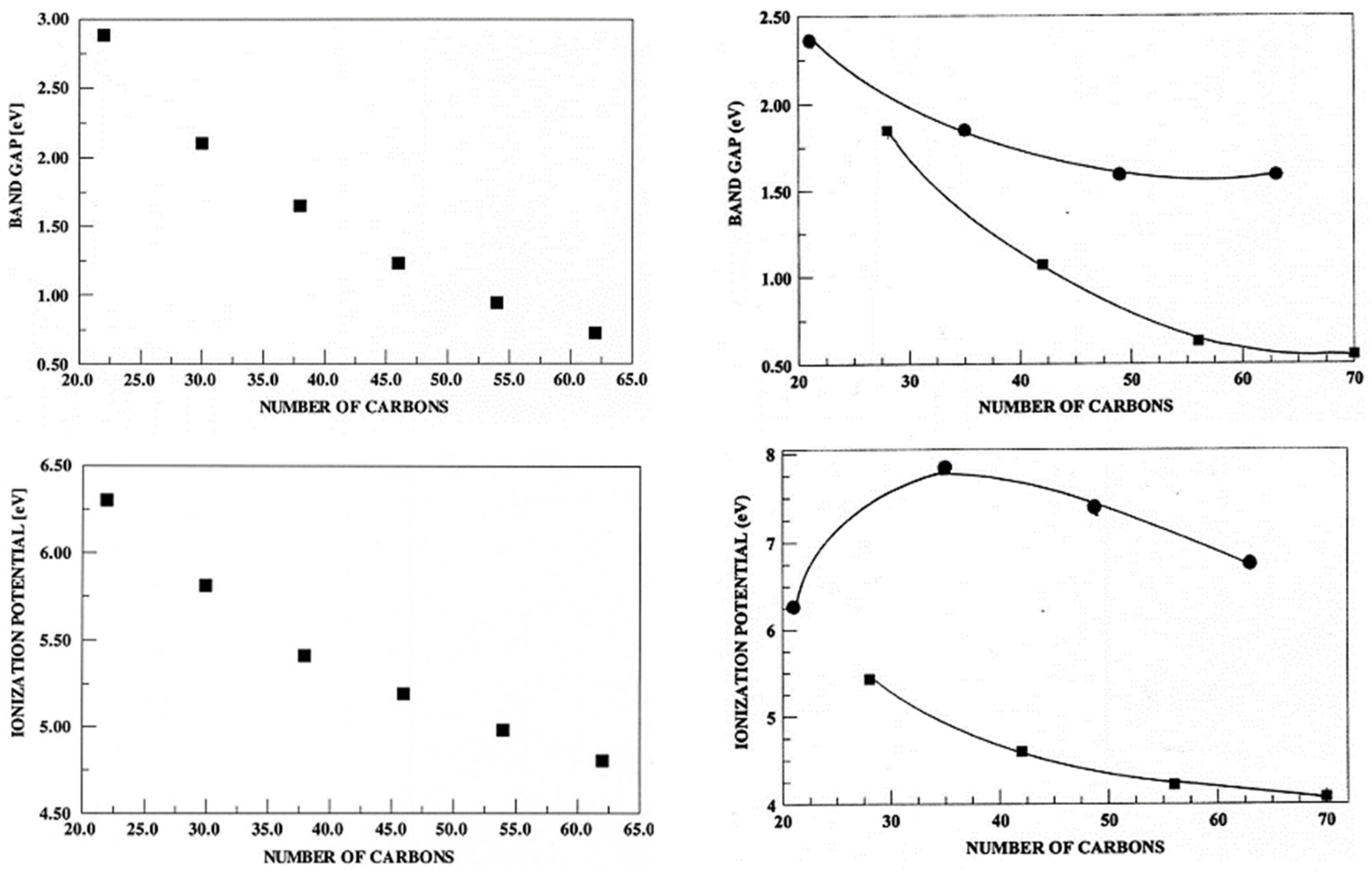
Among these truncated graphene representations, there also exists a high degree of variation in many aspects. To start off, with sizing, models from about 30 to 100 carbon atoms have been used, often truncated with hydrogens at the edge. The arrangement of these atoms also varies. In depictions of graphene, a hexagonal shape is formed where the model is expanded in concentric hexagons. In representing nanoribbons, the model takes a rectangular configuration and may even be wrapped into a cylinder to represent a nanotube. However, from a broader perspective, there is not much difference in these two representations besides the distances between their edges. It can be seen though that the number of carbon atoms in the models does affect their electronic properties, as increasing the number of carbons generally displays a decrease in the band gap and ionization potential (Figure 11).
While these smaller models may not capture the entirety of the fundamental interactions, a truncated model of about 30 atoms was able to represent similar interactions between platinum and graphitic defects like a PBC model. Groves et al. examined the improvement in the binding energy associated with single atom of Pt from adding graphitic defects, suggesting that relevant properties can still be studied accurately in the absence of periodicity. It has been suggested the edge graphitic defects have a higher ORR activity, which these models have the capability to represent [55]. Thus, a side-by-side comparison of this model with a corresponding PBC one would display the significance of computational periodicity and a possible holistic understanding of the electronics behind the benefits of doping.
Between truncated models, they generally all use the same functional of B3LYP for their calculations [10,55,84,88,90,91,92,93]. Even in a study just examining undoped pristine graphene, B3LYP was still the choice functional. This is noteworthy, as B3LYP is regarded to be accurate in treating interactions between organic molecules and metal atoms. While these truncated models are supposed to resemble support for metal catalysts, their nature should be treated more so as a material than as a small organic molecule. Therefore, functionals such as PBE and HSE (tailored for solid state physics) or even ωB97xd (for long-range interactions) may be more representative [94,95,96,97]. There is little difference between HSE/PBE and B3LYP for traditional semiconductors in determining the band gap [98]. Trends across functionals should also be systematically examined in future studies.

3.3. PBC Models

The study of carbon support materials and their properties relies on the conventional use of mimicking a physical material’s surface and bulk. Most theoretical studies involve a graphene model, which is discussed here in detail. While graphene may appear to be a simple single-layer carbon lattice, there are a lot of nuances to be considered in modeling it. The discussion also includes a brief discussion of nanoribbons and other carbon structures.

3.3.1. Graphene

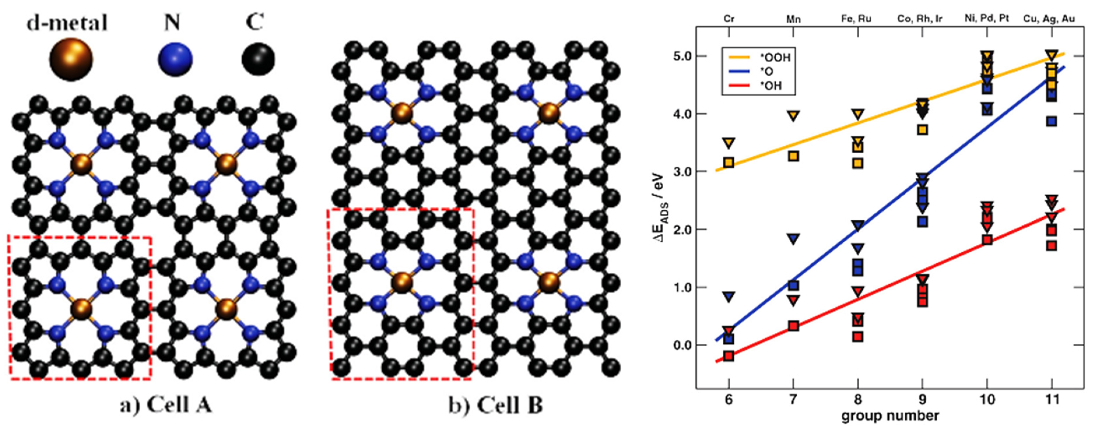
With pristine graphene, the sizing of the unit cell has minimal importance, as any chosen size will accurately portray the extended nature of the graphene material. However, with the addition of defects, the nature of the nitrogen-doped material surface becomes much more complex in terms of accurately representing a physical material. Not only is the sizing of the cell relevant with the introduced nitrogen heteroatoms, vacancies, and metals, but the degrees of freedom also exponentially increase and must be cautiously represented for physical material accuracy. Calle-Vallejo et al. exemplified this need as they used two different unit cells that had subtle differences with their defect-embedded metal active sites (Figure 12).
While the two active sites between the cells appear very similar, the difference is that Cell A has four dehydrogenated pyrrolic defects while Cell B has four pyridinic ones. Given the relative atomic speciation and defect formation, their overall constitution in terms of the number of non-carbon atoms and placement is nearly parallel, making their characterization possibly unresolved without further examination. Due to the differences in functionality, the surrounding carbon lattice also differs. Cell B has more surrounding carbon atoms leading to a lower nitrogen density and a greater atomic separation between defect active sites. Those two factors play relevant roles for examining nitrogen density at a synthetic level. Here, the study explores the reactivity of the active sites to ORR in examining the adsorption with ORR intermediates [99]. Figure 12 shows the spatial and electronic differences between the two cells, meaning that localized representation is affected by the computational design. These parameters must be reminders for carefully approaching theoretical work from the bottom-up, but top-down approaches must also express caution in being too tailored as to act as confirmation rather than support. This can be further explored with two cells with exactly identical active sites but different amounts of surrounding carbons.
The variation in density can be seen across studies where there is 1 graphitic defect per 98 atoms (~1%) to as high as that of Cell A’s (~16%), all contained in the range that is seen at a synthetic level. When compared to truncated models, the spread of defects in PBC models are indefinite in all directions, making this percentage more physically relevant. Seen from truncated models, nitrogen atom spacing plays a role in electronics and would do so more in a larger conjugated system. Stability is also another concern for nitrogen density from localized vacancies and pyrrolic/pyridinic defects. This stability is affected by the steric limitations as “boundary” atoms are not a true edge but are part of the PBCs, limiting their spatial flexibility. Kwak et al. took 752 unit cell models of doped graphene at varying nitrogen concentrations and found the relative stabilities between the different configurations at the same nitrogen concentration [51]. These nitrogen percentages were based off unit cells with only 18 atoms but strongly supported the significance the arrangement of the nitrogen density provided. A simplistic demonstration of this significance was given by Yu et al., when they just investigated graphitic defect interactions with ORR intermediates. They used two models that both had graphitic defects at an 8.33% concentration of nitrogen but with differing local concentrations: the S1 structure had two adjacent carbons between all defects and the S2 structure had three carbons between all defects (Figure 13) [100].
Yu et al. found that localized differences in concentration gave S2 more reactivity for the ORR than S1. A unique metric that was used from this study was a coverage metric. They measured the adsorption energies of ORR absorbates as a function of support coverage by water molecules [100]. This metric might express good correlation with the chemistries happening on a physical surface to better represent the concurrent active sites that are directly in contact with each other, leading to ideas of more surface activity with increasing coverage. It also provides a sense of the materials in a matrix, rather than simply in a vacuum. An area of interest would be examining metal catalyst coverage, alluding to insights into particle aggregation through migration, anchoring, and ripening. Returning to unit cell considerations, coverage must also be carefully designed in attempting to retain an accurate physical surface portrayal. Too great a coverage may result in artificial interactions, especially with a graphene surface, or may drown out the chemical interactions of the active site.
Yu et al. included a larger unit cell (i.e., 6 × 6 transformed into 12 × 12) to examine this coverage metric. This larger unit cell approach is notable for studies that attempt to better model the unit cell for an accurate practical representation [100]. While it is usually the same system explored, the resizing of unit cells does imply a possible sizing effect. Similarly, Musgrave et al. used two unit cells that varied in size but with the same defect model in each. The smaller cell was used for examining particle migration, while the larger one was for calculating the density of states [12]. Concessions to unit cell size for computational cost may be a prominent methodological consideration for future studies.

3.3.2. Nanoribbons

Nanoribbons are a pseudo-one-dimensional structure, as they still retain some width. Another vacuum region is introduced in another dimension so that the distances between the edges of the carbon surface are not interacting. While nanoribbons have been used in practical applications, their appeal as models is their edge representation to study edge defects, such as pyridinic nitrogen defects, as the replacement of edge carbons is more probabilistic during doping. Similar properties, such as formation energies based on defect spacing and favorability, have been elucidated to provide a sense of comparison to other carbon structures [61]. Kwak et al. also took a similar approach for 110 nanoribbon unit cells and found that in this model, stability was greater with more defects since they could be placed at the edge in a zigzag morphology [51]. This morphology is a significant modeling consideration in these models as nanoribbons’ edges are available in two variations: zigzag and armchair. While the two structures appear similar, the difference in their edge truncation has been seen to provide them with a variety of different properties [61,90,93,101,102]. Furthermore, this difference at their edges entails differences in their electronic and magnetic moments, ultimately affecting their defect and catalyst interactions and contributing to modeling considerations.

3.3.3. Other Carbon Structures

Other carbon support models of different dimensionalities have also been explored in theoretical studies, although to a much lesser extent given their relative complexity. Some common models are bilayer surfaces and nanotubes, while there have even been some studies looking at graphdiyne [10,50,57,60,70,96,103,104,105]. These structures, like the graphene and nanotubes, have their own nuances and modeling considerations. With the bilayers, there are modeling considerations with the spacing between the layers and whether the layers are directly overlapping or staggered. With the nanotubes, there are again two different geometries, known as semiconducting and metallic, from their different chemistries [106]. They are often used as single-walled models, although physical materials may have many more walls, which is much more computationally expensive to model. This discernment is important, as the nature of defects changes due to the overarching model choice. For example, a di-vacancy is more favorable on nanotubes than other models, given its geometrical strain, while pyrrolic defects introduce different geometry deformations in different models [61]. It is also important to register if these conformation changes are a product of the computational model or of the actual defect.

4. Metal–Support Interactions for Describing Catalysis

A significant part of studying these metal–support models computationally is how the findings and conclusions can be transferred to practical systems. By designing the computational model to best probe the mechanism of interest, insights into physical properties and phenomena can be predicted, such as degradation and durability [107,108,109].

4.1. Stability

Physical stability is often defined in terms of how long a catalyst will retain its activity, such as in fuel cells. The structure of the catalyst should stay intact with respect to the support as it dictates the electrochemical activity. Thus, the stability of the carbon support and the metal catalyst are defined by the response of their interactions to the stress of the surrounding environment [11]. There are many variables that affect this stability, such as catalyst dissolution and sintering, which correlate to the metrics for the catalyst–support interactions above. These variables are interpreted in different manners resulting in the plethora of different computational methods. For any model, there are always a set of assumptions that are derived from a scientific foundation. However, assumptions do and have been shown to vary between studies. It is important to note that a theoretical model will not map one-to-one to physical reality.
Structural stability has been presented with the formation energies of defects upon supports as a method of comparison relative to each other. With optimization methods, the resulting structure from a set atomic configuration is perceived to be the most stable. A similar approach is taken when metals are introduced to the support. The difference in the formation energies of the catalyst–support with the support and the catalyst in a vacuum amounts to the binding energy of the catalyst to the support [78]. The extent of this stability is represented in the strength of this binding energy. It should be noted that the catalyst introduces degrees of freedom which are not available beforehand as the catalyst may move freely upon the surface or within vacancies and defects. Thus, the optimized binding energies may be further extended to have local minima across the surface, painting a potential energy surface across the support to gauge a sense of reactivity.
Formation energies may also be modified to include other terms that are believed to represent physical systems. Holby et al. adjusted their formation energies with chemical potential considerations, as accepting the chemical nature in situ would affect the overall formation energies. They also offered some other definitions of stability. They presented an overall definition for their material, not only at the catalyst–support location. They had two iron–nitrogen defect systems, varying the distance between the resulting active sites. It was found that there was a tendency for different catalytic scaffolds would form close to each other [110].
The biggest proponent of stability is these catalyst–supports’ resistance to degradation when they are in a medium. Degradation can be studied at an atomic level and with quantum chemical modeling, and active sites affected by degradation can be examined for their resulting activity through examining the kinetics of susceptible bonds in degradation pathways. This modeling provides a representation of the metal catalyst dissolving, the defect changing, or the scaffold binding reactive intermediates that can then be extrapolated to physical stability [111].

4.2. Single-Atom Catalysts (SACs)

With modeling, single-atom catalysts are a common implementation in portraying these interactions between the doped support and catalyst. They offer the simplest representation of a nanoparticle interacting with the support, although recent developments have examined smaller nanoparticles and even the utilization of SACs [112]. Within SACs, we can approach a “direct” model of a single metal atom interacting the support; however, there are many physical variables that are not accounted for in a theoretical model, so it is still far from a “one-to-one mapping”. This representation also extracts valuable information about the fundamental interactions between the catalyst and support and further creates space where other chemical/adsorption events can occur. With a single platinum atom, it has been found that there are preferential binding sites between a support and a metal atom within the vicinity of certain defects [12,84]. Additional properties can be found, such as how a nanoparticle grows given synthetic variables as well as initial atom nucleation and anchoring. A ruthenium atom has been modeled in examining its ORR activity with a particular defect system and various reaction pathways have been theorized with other SAC combinations [113,114]. Theoretical studies make the atomic active site created by these metal atoms and their electronic distribution accessible. A cobalt SAC within a nitrogen defect moiety was tailored with atomic hydrogen and oxygen species to better catalyze the production of H2O2 [115]. This accessibility allowed for methods of simulating the catalytic processes, quantifying against some measures, and ultimately down-selecting to an optimal system [62].
There have been some studies that have explored series of single-atom transition metals over graphene. Nakada and coworkers looked at the adsorption and migration energies for most of the periodic table over pristine graphene in three unique locations. Hossain et al. and Calle-Vallejo et al. examined various transition metals with a four pyridinic nitrogen defects formed by two graphene carbon vacancies [31,74,99]. Arguably, the values that are determined for single atoms may not be directly meaningful, while the relative trends hold suggestive and targeted pursuits for experimental systems. Zhao et al. examined the binding energies of 18 different metal atoms with a three pyridinic/one vacancy defect on graphene, and predicted that molybdenum and chromium would be the optimal choice for a nitrogen reduction reaction with a low overpotential and high selectivity [30]. Such a comparative approach with many metals provides a fundamental understanding of how a metal interacts with supports. Other results have indicated that the catalytic activity is closely related to the coordination of SACs and the surrounding electronegativity, where for the hydrogen reduction reaction specifically, the metallic valance d z 2 orbital and the antibonding orbital have the largest contribution to catalytic activity [31,116]. These investigations bolster the claim that chemical intuition along with chemical modeling benchmarked with experimentation is an exciting avenue for rationally designed catalytic systems.
With SACs, there is an overlap between nanoparticles and dispersed atomic catalysts/embedded metals within the support. Similar investigations are performed with these formed active sites of dispersed embedded metals within the material, such as examining their activity for the ORR. Sun et al. examined embedded Co atoms within two different types of pyridinic vacancies. A 32-atom unit cell was used, providing a precedence for a metal to nitrogen ratio [117]. Holby and coworkers also introduced an active site between two truncations of graphene [110]. This reinforced the notion that the surrounding carbon model ultimately plays a role in the chemistry of the active site. FeN4 (an iron atom within a vacancy surrounded by four pyridinic/pyrrolic defects on a nitrogen-doped carbon support) moiety has been a popular defect structure. Other metal atoms with that defect structure, especially non-platinum group metals, have been examined as well, and even dual SACs have been proposed [118,119].
From XANES experiments, it was found that FeN4–C12 sites specifically were the primary active site among these types of sites. From XPS and XRD, FeN4–C8 sites were the ones characterized to be the ORR active sites. Furthermore, both FeN4–C8 and FeN4–C10 sites exhibited higher activity for the ORR than FeN4–C12 sites (Figure 14). Further XANES studies presented that these similar active sites within different carbon environments provided dissimilar catalytic activity. Liu et al. studied their comparative formation energies and found that C10 site formation was favored compared to the C8 and C12 sites unless there were surrounding vacancy spaces or “carbon pores” (depicted in Figure 14b,c). These three structures shared a planar geometry with a representative square ligand field, meaning that the Fe’s 3 d x y ,   4 s ,   4 p x , and 4 p y orbitals overlapped with the nitrogen’s hybridized orbitals, supported by the calculated partial density of states. This left Fe’s four other d orbitals to interact with the ORR reactants. It was then seen that the 2 p orbitals of O2 overlapped with 3 d z 2 of Fe in C10 and C12 but with 3 d x z / 3 d y z in C8 in which the interacting orbitals were closer to the Fermi level. Most importantly, it was presented that the metal catalyst nonbonding orbitals could be tuned by the π-electron delocalization of the surrounding carbon support [120].
Given the non-limited freedom of theoretical modeling and exploration, many different modeling avenues can be taken, but the conclusions from these models should also be evaluated. There are systematic studies of different metals embedded within these active sites providing both fundamental information about the defects through their interactions with the metals and their electronic relationships, allowing for fine tuning of the desired active site reactivity [78]. Moreover, modeling can be performed with multiple defects within a localized area to explore migration and atomic preferences to certain defects. Bulushev et al. placed multiple defects within a graphene fragment and optimized a palladium atom from different locations, most notably between two different defects. It was found that the atom tended to move away from graphitic defects and towards defect-vacancy sites [121]. These models offer confirmation of which defects the catalysts are likely to interact with on a physical material with more than one type of defect.

4.3. Nanoclusters

Not all synthetic routes aim to produce SACs, in which the interactions between multi-atom catalysts and support remain necessary. Nanoparticle sizing has decreased to nanocluster sizes, making their sizing on par with computational considerations. Compared to SACs, they offer unique research and interactions due to their geometries. They can replicate the geometries of crystal structures where a certain facet of the nanocluster would interact with the support. A study assumed nanoclusters of 13 atoms in icosahedral configurations across 30 metals to examine their nucleation to a carbon nanotube. With this geometric assumption, they observed the center of gravity for the occupied d-states of the nanoclusters to describe their adsorption [60].
Two other studies examined Pt nanoclusters beyond 13 atoms and noticed discrete geometric changes when placed on the support, implying that the conformational changes may have been part of describing the nanoclusters’ stability. One of those studies also used different sized unit cells for the support to look at the larger sized nanoclusters. They found that the support also had conformational changes, and that nanocluster distances between periodic images had an effect on the relaxed state of the nanocluster [122,123]. Another recent study even examined palladium nanoclusters of up to 300 atoms, where they found that nanoclusters on that magnitude included huge conformation changes to the support [124]. Thus, nanocluster representations may provide valuable unconsidered metrics for defining these interactions that may better describe the nanoparticle behavior seen in characterization methods. By adding this consideration to theoretical modeling, it extends an aspect of the model to represent non-SAC considerations that are present, even among targeting SACs. Another representation had nickel nanoclusters from one to four atoms over a series of pyridinic defects surrounding a vacancy on graphene. While examining the most stable adsorbed nanoclusters, it was seen that the Ni2 nanocluster was embedded in the vacancies such that one atom was above the sheet and the other was below [38]. There is much to be explored still with nanocluster representations, as that Ni2 conformation may not have been the most stable if the material was a bilayer of graphene. With increasing atoms within a nanocluster, many degrees of freedom are introduced that may play a significant role in defining these catalyst–support interactions.

5. Concluding Remarks and Outlook

It is necessary to bridge the gap between the findings of computational modeling and the catalytic activity observed under practical operating conditions [28]. The study of catalysts over supports is a necessary first step in understanding their fundamental interactions to rationally design systems for targeted applications. Theoretical work assists in approaching those fundamental interactions with atomic modeling. However, it is essential to consider computational parameterization and the physical significance drawn from it. As with any experimental method, the computational parameters must also be analyzed to determine the nuances of the conclusions by evaluating whether the results may contain computational artifacts. Rigorously developed models and protocols with well-defined and understood metrics are needed in studying these interactions to develop a holistic view that can be best relayed to the physical identification and treatment of these novel materials. Though improving the understanding of these systems by computational means is not a trivial task, advances in both computational infrastructure and experimental measurements show promise for future studies. The field is opening towards many different possibilities, such as co-doping and novel defects, with new emerging technological implementations, such as machine learning [125,126,127]. However, with added degrees of freedom, more computational artifacts may appear, and it will be essential to distinguish and withdraw meaningful results.

Author Contributions

V.N.—primary author in researching the literature and preparing and editing the manuscript. S.V.—mentorship and editing the manuscript. All authors have read and agreed to the published version of the manuscript.

Funding

This research received no external funding.

Data Availability Statement

No data were generated in the creation of this review.

Acknowledgments

The content in this review is also partially published in the author’s dissertation work and is thus acknowledged [128]. Additions on top of the shared dissertation content were performed between two of the affiliated institutions and we acknowledge both institutions. However, other than the original dissertation work, it has not been published anywhere else besides in this journal. The authors are happy to field any inquiries between the two bodies of work.

Conflicts of Interest

The authors declare no conflicts of interest.

Abbreviations

DFT—density functional theory; PBC—periodic boundary condition; SACs—single-atom catalysts; ORR—oxygen reduction reaction.

References

  1. Zhang, J.; Terrones, M.; Park, C.R.; Mukherjee, R.; Monthioux, M.; Koratkar, N.; Kim, Y.S.; Hurt, R.; Frackowiak, E.; Enoki, T.; et al. Carbon science in 2016: Status, challenges and perspectives. Carbon 2016, 98, 708–732. [Google Scholar] [CrossRef]
  2. Dai, L.; Xue, Y.; Qu, L.; Choi, H.J.; Baek, J.B. Metal-Free Catalysts for Oxygen Reduction Reaction. Chem. Rev. 2015, 115, 4823–4892. [Google Scholar] [CrossRef]
  3. Chen, D.; Tang, L.; Li, J. Graphene-based materials in electrochemistry. Chem. Soc. Rev. 2010, 39, 3157–3180. [Google Scholar] [CrossRef]
  4. Geim, A.K.; Novoselov, K.S. The rise of graphene. Nat. Mater. 2007, 6, 183–191. [Google Scholar] [CrossRef]
  5. Blaikie, A.; Miller, D.; Alemán, B.J. A fast and sensitive room-temperature graphene nanomechanical bolometer. Nat. Commun. 2019, 10, 4276. [Google Scholar] [CrossRef] [PubMed]
  6. Bakharev, P.V.; Huang, M.; Saxena, M.; Lee, S.W.; Joo, S.H.; Park, S.O.; Dong, J.; Camacho-Mojica, D.C.; Jin, S.; Kwon, Y.; et al. Chemically induced transformation of chemical vapour deposition grown bilayer graphene into fluorinated single-layer diamond. Nat. Nanotechnol. 2019, 15, 59–66. [Google Scholar] [CrossRef]
  7. Gao, Y.; Cao, T.; Cellini, F.; Berger, C.; De Heer, W.A.; Tosatti, E.; Riedo, E.; Bongiorno, A. Ultrahard carbon film from epitaxial two-layer graphene. Nat. Nanotechnol. 2018, 13, 133–138. [Google Scholar] [CrossRef]
  8. Yang, Z.; Nie, H.; Chen, X.; Chen, X.; Huang, S. Recent progress in doped carbon nanomaterials as effective cathode catalysts for fuel cell oxygen reduction reaction. J. Power Sources 2013, 236, 238–249. [Google Scholar] [CrossRef]
  9. Antolini, E. Graphene as a new carbon support for low-temperature fuel cell catalysts. Appl. Catal. B Environ. 2012, 123–124, 52–68. [Google Scholar] [CrossRef]
  10. Wang, Y.; Song, W.; Li, M.; Wu, Z. Oxygen reduction reaction mechanisms on heteroatom-doped single-walled carbon nanotube catalysts: Insights from a theoretical study. J. Electrochem. Soc. 2019, 166, F670–F678. [Google Scholar] [CrossRef]
  11. Antolini, E.; Salgado, J.R.C.; Gonzalez, E.R. The stability of Pt-M (M = first row transition metal) alloy catalysts and its effect on the activity in low temperature fuel cells. A literature review and tests on a Pt-Co catalyst. J. Power Sources 2006, 160, 957–968. [Google Scholar] [CrossRef]
  12. Muhich, C.L.; Westcott, J.Y.; Morris, T.C.; Weimer, A.W.; Musgrave, C.B. The effect of N and B doping on graphene and the adsorption and migration behavior of Pt atoms. J. Phys. Chem. C 2013, 117, 10523–10535. [Google Scholar] [CrossRef]
  13. Wu, H.; Wexler, D.; Liu, H. Pt-Ni/C catalysts using different carbon supports for the cathode of the proton exchange membrane fuel cell (PEMFC). Mater. Chem. Phys. 2012, 136, 845–849. [Google Scholar] [CrossRef]
  14. Hsieh, S.H.; Hsu, M.C.; Liu, W.L.; Chen, W.J. Study of Pt catalyst on graphene and its application to fuel cell. Appl. Surf. Sci. 2013, 277, 223–230. [Google Scholar] [CrossRef]
  15. Shao, Y.; Yin, G.; Gao, Y. Understanding and approaches for the durability issues of Pt-based catalysts for PEM fuel cell. J. Power Sources 2007, 171, 558–566. [Google Scholar] [CrossRef]
  16. Holby, E.F.; Sheng, W.; Shao-Horn, Y.; Morgan, D. Pt nanoparticle stability in PEM fuel cells: Influence of particle size distribution and crossover hydrogen. Energy Environ. Sci. 2009, 2, 865–871. [Google Scholar] [CrossRef]
  17. Speder, J.; Zana, A.; Spanos, I.; Kirkensgaard, J.J.K.; Mortensen, K.; Hanzlik, M.; Arenz, M. Comparative degradation study of carbon supported proton exchange membrane fuel cell electrocatalysts—The influence of the platinum to carbon ratio on the degradation rate. J. Power Sources 2014, 261, 14–22. [Google Scholar] [CrossRef]
  18. Zhou, Z.M.; Shao, Z.G.; Qin, X.P.; Chen, X.G.; Wei, Z.D.; Yi, B.L. Durability study of Pt-Pd/C as PEMFC cathode catalyst. Int. J. Hydrogen Energy 2010, 35, 1719–1726. [Google Scholar] [CrossRef]
  19. Dubau, L.; Castanheira, L.; Chatenet, M.; Maillard, F.; Dillet, J.; Maranzana, G.; Abbou, S.; Lottin, O.; De Moor, G.; El Kaddouri, A.; et al. Carbon corrosion induced by membrane failure: The weak link of PEMFC long-term performance. Int. J. Hydrogen Energy 2014, 39, 21902–21914. [Google Scholar] [CrossRef]
  20. Shao, Y.; Zhang, S.; Wang, C.; Nie, Z.; Liu, J.; Wang, Y.; Lin, Y. Highly durable graphene nanoplatelets supported Pt nanocatalysts for oxygen reduction. J. Power Sources 2010, 195, 4600–4605. [Google Scholar] [CrossRef]
  21. Pylypenko, S.; Borisevich, A.; More, K.L.; Corpuz, A.R.; Holme, T.; Dameron, A.A.; Olson, T.S.; Dinh, H.N.; Gennett, T.; O’Hayre, R. Nitrogen: Unraveling the secret to stable carbon-supported Pt-alloy electrocatalysts. Energy Environ. Sci. 2013, 6, 2957–2964. [Google Scholar] [CrossRef]
  22. Wood, K.N.; O’Hayre, R.; Pylypenko, S. Recent progress on nitrogen/carbon structures designed for use in energy and sustainability applications. Energy Environ. Sci. 2014, 7, 1212–1249. [Google Scholar] [CrossRef]
  23. Paraknowitsch, J.P.; Thomas, A. Doping carbons beyond nitrogen: An overview of advanced heteroatom doped carbons with boron, sulphur and phosphorus for energy applications. Energy Environ. Sci. 2013, 6, 2839–2855. [Google Scholar] [CrossRef]
  24. Sinthika, S.; Waghmare, U.V.; Thapa, R. Structural and Electronic Descriptors of Catalytic Activity of Graphene-Based Materials: First-Principles Theoretical Analysis. Small 2018, 14, 1703609. [Google Scholar] [CrossRef]
  25. Deng, D.; Pan, X.; Yu, L.; Cui, Y.; Jiang, Y.; Qi, J.; Li, W.X.; Fu, Q.; Ma, X.; Xue, Q.; et al. Toward N-doped graphene via solvothermal synthesis. Chem. Mater. 2011, 23, 1188–1193. [Google Scholar] [CrossRef]
  26. Jin, H.; Guo, C.; Liu, X.; Liu, J.; Vasileff, A.; Jiao, Y.; Zheng, Y.; Qiao, S.Z. Emerging Two-Dimensional Nanomaterials for Electrocatalysis. Chem. Rev. 2018, 118, 6337–6408. [Google Scholar] [CrossRef] [PubMed]
  27. Campisi, S.; Chan-Thaw, C.E.; Villa, A. Understanding heteroatom-mediated metal-support interactions in functionalized carbons: A perspective review. Appl. Sci. 2018, 8, 1159. [Google Scholar] [CrossRef]
  28. Singh, S.K.; Takeyasu, K.; Nakamura, J. Active Sites and Mechanism of Oxygen Reduction Reaction Electrocatalysis on Nitrogen-Doped Carbon Materials. Adv. Mater. 2019, 31, e1804297. [Google Scholar] [CrossRef]
  29. Corpuz, A.R.; Olson, T.S.; Joghee, P.; Pylypenko, S.; Dameron, A.A.; Dinh, H.N.; O’Neill, K.J.; Hurst, K.E.; Bender, G.; Gennett, T.; et al. Effect of a nitrogen-doped PtRu/carbon anode catalyst on the durability of a direct methanol fuel cell. J. Power Sources 2012, 217, 142–151. [Google Scholar] [CrossRef]
  30. Zhao, W.; Zhang, L.; Luo, Q.; Hu, Z.; Zhang, W.; Smith, S.; Yang, J. Single Mo1(Cr1) Atom on Nitrogen-Doped Graphene Enables Highly Selective Electroreduction of Nitrogen into Ammonia. ACS Catal. 2019, 9, 3419–3425. [Google Scholar] [CrossRef]
  31. Hossain, M.D.; Liu, Z.; Zhuang, M.; Yan, X.; Xu, G.L.; Gadre, C.A.; Tyagi, A.; Abidi, I.H.; Sun, C.J.; Wong, H.; et al. Rational Design of Graphene-Supported Single Atom Catalysts for Hydrogen Evolution Reaction. Adv. Energy Mater. 2019, 9, 1803689. [Google Scholar] [CrossRef]
  32. Wang, L.; Sofer, Z.; Pumera, M. Will Any Crap We Put into Graphene Increase Its Electrocatalytic Effect? ACS Nano 2020, 14, 21–25. [Google Scholar] [CrossRef] [PubMed]
  33. Jiao, Y.; Zheng, Y.; Davey, K.; Qiao, S.Z. Activity origin and catalyst design principles for electrocatalytic hydrogen evolution on heteroatom-doped graphene. Nat. Energy 2016, 1, 16130. [Google Scholar] [CrossRef]
  34. Zhao, Z.; Xia, Z. Design Principles for Dual-Element-Doped Carbon Nanomaterials as Efficient Bifunctional Catalysts for Oxygen Reduction and Evolution Reactions. ACS Catal. 2016, 6, 1553–1558. [Google Scholar] [CrossRef]
  35. Ortiz-Medina, J.; Wang, Z.; Cruz-Silva, R.; Morelos-Gomez, A.; Wang, F.; Yao, X.; Terrones, M.; Endo, M. Defect Engineering and Surface Functionalization of Nanocarbons for Metal-Free Catalysis. Adv. Mater. 2019, 31, e1805717. [Google Scholar] [CrossRef]
  36. Primbs, M.; Sun, Y.; Roy, A.; Malko, D.; Mehmood, A.; Sougrati, M.T.; Blanchard, P.Y.; Granozzi, G.; Kosmala, T.; Daniel, G.; et al. Establishing reactivity descriptors for platinum group metal (PGM)-free Fe-N-C catalysts for PEM fuel cells. Energy Environ. Sci. 2020, 13, 2480–2500. [Google Scholar] [CrossRef]
  37. Axet, M.R.; Durand, J.; Gouygou, M.; Serp, P. Surface coordination chemistry on graphene and two-dimensional carbon materials for well-defined single atom supported catalysts. In Advances in Organometallic Chemistry; Academic Press Inc.: Cambridge, MA, USA, 2019; Volume 71, pp. 53–174. [Google Scholar] [CrossRef]
  38. Gao, Z.; Li, A.; Liu, X.; Ma, C.; Li, X.; Yang, W.; Ding, X. Density functional study of the adsorption of NO on Ni n (n = 1, 2, 3 and 4) clusters doped functionalized graphene support. Appl. Surf. Sci. 2019, 481, 940–950. [Google Scholar] [CrossRef]
  39. Krishnan, R.; Wu, S.Y.; Chen, H.T. Catalytic CO oxidation on B-doped and BN co-doped penta-graphene: A computational study. Phys. Chem. Chem. Phys. 2018, 20, 26414–26421. [Google Scholar] [CrossRef]
  40. Workman, M.J.; Dzara, M.; Ngo, C.; Pylypenko, S.; Serov, A.; McKinney, S.; Gordon, J.; Atanassov, P.; Artyushkova, K. Platinum group metal-free electrocatalysts: Effects of synthesis on structure and performance in proton-exchange membrane fuel cell cathodes. J. Power Sources 2017, 348, 30–39. [Google Scholar] [CrossRef]
  41. Holby, E.F.; Zelenay, P. Linking structure to function: The search for active sites in non-platinum group metal oxygen reduction reaction catalysts. Nano Energy 2016, 29, 54–64. [Google Scholar] [CrossRef]
  42. Saha, D.; Kienbaum, M.J. Role of oxygen, nitrogen and sulfur functionalities on the surface of nanoporous carbons in CO2 adsorption: A critical review. Microporous Mesoporous Mater. 2019, 287, 29–55. [Google Scholar] [CrossRef]
  43. Artyushkova, K.; Matanovic, I.; Halevi, B.; Atanassov, P. Oxygen Binding to Active Sites of Fe-N-C ORR Electrocatalysts Observed by Ambient-Pressure XPS. J. Phys. Chem. C 2017, 121, 2836–2843. [Google Scholar] [CrossRef]
  44. Artyushkova, K.; Kiefer, B.; Halevi, B.; Knop-Gericke, A.; Schlogl, R.; Atanassov, P. Density functional theory calculations of XPS binding energy shift for nitrogen-containing graphene-like structures. Chem. Commun. 2013, 49, 2539–2541. [Google Scholar] [CrossRef] [PubMed]
  45. Matanovic, I.; Artyushkova, K.; Strand, M.B.; Dzara, M.J.; Pylypenko, S.; Atanassov, P. Core Level Shifts of Hydrogenated Pyridinic and Pyrrolic Nitrogen in the Nitrogen-Containing Graphene-Based Electrocatalysts: In-Plane vs Edge Defects. J. Phys. Chem. C 2016, 120, 29225–29232. [Google Scholar] [CrossRef]
  46. Ye, R.; Dong, J.; Wang, L.; Mendoza-Cruz, R.; Li, Y.; An, P.F.; Yacamán, M.J.; Yakobson, B.I.; Chen, D.; Tour, J.M. Manganese deception on graphene and implications in catalysis. Carbon 2018, 132, 623–631. [Google Scholar] [CrossRef]
  47. Wang, T.; Chen, Z.X.; Chen, Y.G.; Yang, L.J.; Yang, X.D.; Ye, J.Y.; Xia, H.P.; Zhou, Z.Y.; Sun, S.G. Identifying the Active Site of N-Doped Graphene for Oxygen Reduction by Selective Chemical Modification. ACS Energy Lett. 2018, 3, 986–991. [Google Scholar] [CrossRef]
  48. Zhou, Y.; Neyerlin, K.; Olson, T.S.; Pylypenko, S.; Bult, J.; Dinh, H.N.; Gennett, T.; Shao, Z.; O’Hayre, R. Enhancement of Pt and Pt-alloy fuel cell catalyst activity and durability via nitrogen-modified carbon supports. Energy Environ. Sci. 2010, 3, 1437–1446. [Google Scholar] [CrossRef]
  49. Chaban, V.V.; Prezhdo, O. V Nitrogen–Nitrogen Bonds Undermine Stability of N-Doped Graphene. J. Am. Chem. Soc 2015, 137, 11688–11694. [Google Scholar] [CrossRef]
  50. Holme, T.; Zhou, Y.; Pasquarelli, R.; O’Hayre, R. First principles study of doped carbon supports for enhanced platinum catalysts. Phys. Chem. Chem. Phys. 2010, 12, 9461–9468. [Google Scholar] [CrossRef]
  51. Kwak, D.; Khetan, A.; Noh, S.; Pitsch, H.; Han, B. First principles study of morphology, doping level, and water solvation effects on the catalytic mechanism of nitrogen-doped graphene in the oxygen reduction reaction. ChemCatChem 2014, 6, 2662–2670. [Google Scholar] [CrossRef]
  52. Herath, D.; Dinadayalane, T. Computational investigation of double nitrogen doping on graphene. J. Mol. Model. 2018, 24, 26. [Google Scholar] [CrossRef] [PubMed]
  53. Jeon, I.Y.; Choi, H.J.; Ju, M.J.; Choi, I.T.; Lim, K.; Ko, J.; Kim, H.K.; Kim, J.C.; Lee, J.J.; Shin, D.; et al. Direct nitrogen fixation at the edges of graphene nanoplatelets as efficient electrocatalysts for energy conversion. Sci. Rep. 2013, 3, srep02260. [Google Scholar] [CrossRef] [PubMed]
  54. Schiros, T.; Nordlund, D.; Pálová, L.; Prezzi, D.; Zhao, L.; Kim, K.S.; Wurstbauer, U.; Gutiérrez, C.; Delongchamp, D.; Jaye, C.; et al. Connecting dopant bond type with electronic structure in n-doped graphene. Nano Lett. 2012, 12, 4025–4031. [Google Scholar] [CrossRef]
  55. Matsuyama, H.; Akaishi, A.; Nakamura, J. Effect of water on the manifestation of the reaction selectivity of nitrogen-doped graphene nanoclusters toward oxygen reduction reaction. ACS Omega 2019, 4, 3832–3838. [Google Scholar] [CrossRef] [PubMed]
  56. Gadipelli, S.; Guo, Z.X. Graphene-based materials: Synthesis and gas sorption, storage and separation. Prog. Mater. Sci. 2015, 69, 1–60. [Google Scholar] [CrossRef]
  57. Tang, Y.; Chen, W.; Li, C.; Li, W.; Dai, X. Geometric stability, electronic structure, and intercalation mechanism of Co adatom anchors on graphene sheets. J. Phys. Condens. Matter 2015, 27, 255009. [Google Scholar] [CrossRef]
  58. Vinayan, B.P. Heteroatom-Doped Graphene-Based Hybrid Materials for Hydrogen Energy Conversion. In Recent Advances in Graphene Research; InTech: London, UK, 2016; pp. 177–194. ISBN 978-953-307-695-9. [Google Scholar]
  59. Dong, Y.; Gahl, M.T.; Zhang, C.; Lin, J. Computational study of precision nitrogen doping on graphene nanoribbon edges. Nanotechnology 2017, 28, 505602. [Google Scholar] [CrossRef]
  60. Peraça, C.S.T.; Nagurniak, G.R.; Orenha, R.P.; Parreira, R.L.T.; Piotrowski, M.J. A theoretical indicator of transition-metal nanoclusters applied in the carbon nanotube nucleation process: A DFT study. Dalt. Trans. 2020, 49, 492–503. [Google Scholar] [CrossRef]
  61. Li, Y.; Zhou, Z.; Shen, P.; Chen, Z. Spin gapless semiconductor-metal-half-metal properties in nitrogen-doped zigzag graphene nanoribbons. ACS Nano 2009, 3, 1952–1958. [Google Scholar] [CrossRef]
  62. Guo, J.; Huo, J.; Liu, Y.; Wu, W.; Wang, Y.; Wu, M.; Liu, H.; Wang, G. Nitrogen-Doped Porous Carbon Supported Nonprecious Metal Single-Atom Electrocatalysts: From Synthesis to Application. Small Methods 2019, 3, 1900159. [Google Scholar] [CrossRef]
  63. He, L.; Weniger, F.; Neumann, H.; Beller, M. Synthesis, Characterization, and Application of Metal Nanoparticles Supported on Nitrogen-Doped Carbon: Catalysis beyond Electrochemistry. Angew. Chemie Int. Ed. 2016, 55, 12582–12594. [Google Scholar] [CrossRef] [PubMed]
  64. Cao, Y.; Mao, S.; Li, M.; Chen, Y.; Wang, Y. Metal/Porous Carbon Composites for Heterogeneous Catalysis: Old Catalysts with Improved Performance Promoted by N-Doping. ACS Catal. 2017, 7, 8090–8112. [Google Scholar] [CrossRef]
  65. Salinas-Torres, D.; Navlani-García, M.; Mori, K.; Kuwahara, Y.; Yamashita, H. Nitrogen-doped carbon materials as a promising platform toward the efficient catalysis for hydrogen generation. Appl. Catal. A Gen. 2019, 571, 25–41. [Google Scholar] [CrossRef]
  66. Ma, R.; Lin, G.; Zhou, Y.; Liu, Q.; Zhang, T.; Shan, G.; Yang, M.; Wang, J. A review of oxygen reduction mechanisms for metal-free carbon-based electrocatalysts. Npj Comput. Mater. 2019, 5, 78. [Google Scholar] [CrossRef]
  67. Wang, H.; Maiyalagan, T.; Wang, X. Review on recent progress in nitrogen-doped graphene: Synthesis, characterization, and its potential applications. ACS Catal. 2012, 2, 781–794. [Google Scholar] [CrossRef]
  68. Nørskov, J.K.; Bligaard, T.; Rossmeisl, J.; Christensen, C.H. Towards the computational design of solid catalysts. Nat. Chem. 2009, 1, 37–46. [Google Scholar] [CrossRef]
  69. Kratzer, P.; Neugebauer, J. The basics of electronic structure theory for periodic systems. Front. Chem. 2019, 7, 106. [Google Scholar] [CrossRef]
  70. BASIUK, V.A. Electron Smearing in DFT Calculations: A Case Study of Doxorubicin Interaction with Single-Walled Carbon Nanotubes. Int. J. Quantum Chem. 2011, 111, 4020–4029. [Google Scholar] [CrossRef]
  71. Reda, M.; Hansen, H.A.; Vegge, T. DFT study of stabilization effects on N-doped graphene for ORR catalysis. Catal. Today 2018, 312, 118–125. [Google Scholar] [CrossRef]
  72. Sui, S.; Wang, X.; Zhou, X.; Su, Y.; Riffat, S.; Liu, C. jun A comprehensive review of Pt electrocatalysts for the oxygen reduction reaction: Nanostructure, activity, mechanism and carbon support in PEM fuel cells. J. Mater. Chem. A 2017, 5, 1808–1825. [Google Scholar] [CrossRef]
  73. Xu, C.; Yang, W.; Ma, G.; Che, S.; Li, Y.; Jia, Y.; Chen, N.; Huang, G.; Li, Y. Edge-Nitrogen Enriched Porous Carbon Nanosheets Anodes with Enlarged Interlayer Distance for Fast harging Sodium-Ion Batteries. Small 2022, 18, 2204375. [Google Scholar] [CrossRef]
  74. Nakada, K.; Ishii, A. Migration of adatom adsorption on graphene using DFT calculation. Solid State Commun. 2011, 151, 13–16. [Google Scholar] [CrossRef]
  75. Li, X.F.; Li, Q.K.; Cheng, J.; Liu, L.; Yan, Q.; Wu, Y.; Zhang, X.H.; Wang, Z.Y.; Qiu, Q.; Luo, Y. Conversion of Dinitrogen to Ammonia by FeN3-Embedded Graphene. J. Am. Chem. Soc. 2016, 138, 8706–8709. [Google Scholar] [CrossRef] [PubMed]
  76. Artyushkova, K.; Serov, A.; Rojas-Carbonell, S.; Atanassov, P. Chemistry of Multitudinous Active Sites for Oxygen Reduction Reaction in Transition Metal-Nitrogen-Carbon Electrocatalysts. J. Phys. Chem. C 2015, 119, 25917–25928. [Google Scholar] [CrossRef]
  77. She, Y.; Chen, J.; Zhang, C.; Lu, Z.; Ni, M.; Sit, P.H.L.; Leung, M.K.H. Nitrogen-doped graphene derived from ionic liquid as metal-free catalyst for oxygen reduction reaction and its mechanisms. Appl. Energy 2018, 225, 513–521. [Google Scholar] [CrossRef]
  78. Yang, M.; Wang, L.; Li, M.; Hou, T.; Li, Y. Structural stability and O2 dissociation on nitrogen-doped graphene with transition metal atoms embedded: A first-principles study. AIP Adv. 2015, 5, 067136. [Google Scholar] [CrossRef]
  79. Lai, L.; Potts, J.R.; Zhan, D.; Wang, L.; Poh, C.K.; Tang, C.; Gong, H.; Shen, Z.; Lin, J.; Ruoff, R.S. Exploration of the active center structure of nitrogen-doped graphene-based catalysts for oxygen reduction reaction. Energy Environ. Sci. 2012, 5, 7936–7942. [Google Scholar] [CrossRef]
  80. Tai, S.H.; Chang, B.K. Effect of nitrogen-doping configuration in graphene on the oxygen reduction reaction. RSC Adv. 2019, 9, 6035–6041. [Google Scholar] [CrossRef]
  81. Li, K.; Li, N.; Yan, N.; Wang, T.; Zhang, Y.; Song, Q.; Li, H. Adsorption of small hydrocarbons on pristine, N-doped and vacancy graphene by DFT study. Appl. Surf. Sci. 2020, 515, 146028. [Google Scholar] [CrossRef]
  82. Wei, Q.; Tong, X.; Zhang, G.; Qiao, J.; Gong, Q.; Sun, S. Nitrogen-doped carbon nanotube and graphene materials for oxygen reduction reactions. Catalysts 2015, 5, 1574–1602. [Google Scholar] [CrossRef]
  83. Yan, P.; Liu, J.; Yuan, S.; Liu, Y.; Cen, W.; Chen, Y. The promotion effects of graphitic and pyridinic N combinational doping on graphene for ORR. Appl. Surf. Sci. 2018, 445, 398–403. [Google Scholar] [CrossRef]
  84. Groves, M.N.; Chan, A.S.W.; Malardier-Jugroot, C.; Jugroot, M. Improving platinum catalyst binding energy to graphene through nitrogen doping. Chem. Phys. Lett. 2009, 481, 214–219. [Google Scholar] [CrossRef]
  85. Inagaki, M.; Toyoda, M.; Soneda, Y.; Morishita, T. Nitrogen-doped carbon materials. Carbon 2018, 132, 104–140. [Google Scholar] [CrossRef]
  86. Arrigo, R.; Schuster, M.E.; Xie, Z.; Yi, Y.; Wowsnick, G.; Sun, L.L.; Hermann, K.E.; Friedrich, M.; Kast, P.; Hävecker, M.; et al. Nature of the N-Pd interaction in nitrogen-doped carbon nanotube catalysts. ACS Catal. 2015, 5, 2740–2753. [Google Scholar] [CrossRef]
  87. Noffke, B.W.; Li, Q.; Raghavachari, K.; Li, L.S. A Model for the pH-Dependent Selectivity of the Oxygen Reduction Reaction Electrocatalyzed by N-Doped Graphitic Carbon. J. Am. Chem. Soc. 2016, 138, 13923–13929. [Google Scholar] [CrossRef]
  88. Zhang, L.; Niu, J.; Dai, L.; Xia, Z. Effect of microstructure of nitrogen-doped graphene on oxygen reduction activity in fuel cells. Langmuir 2012, 28, 7542–7550. [Google Scholar] [CrossRef]
  89. Matanovic, I.; Artyushkova, K.; Atanassov, P. Understanding PGM-free catalysts by linking density functional theory calculations and structural analysis: Perspectives and challenges. Curr. Opin. Electrochem. 2018, 9, 137–144. [Google Scholar] [CrossRef]
  90. Owens, F.J. Electronic and magnetic properties of armchair and zigzag graphene nanoribbons. J. Chem. Phys. 2008, 128, 194701. [Google Scholar] [CrossRef]
  91. Sidik, R.A.; Anderson, A.B.; Subramanian, N.P.; Kumaraguru, S.P.; Popov, B.N. O2 reduction on graphite and nitrogen-doped graphite: Experiment and theory. J. Phys. Chem. B 2006, 110, 1787–1793. [Google Scholar] [CrossRef]
  92. Jiao, Y.; Zheng, Y.; Jaroniec, M.; Qiao, S.Z. Origin of the electrocatalytic oxygen reduction activity of graphene-based catalysts: A roadmap to achieve the best performance. J. Am. Chem. Soc. 2014, 136, 4394–4403. [Google Scholar] [CrossRef]
  93. Kim, J.; Lee, N.; Min, Y.H.; Noh, S.; Kim, N.K.; Jung, S.; Joo, M.; Yamada, Y. Distinguishing Zigzag and Armchair Edges on Graphene Nanoribbons by X-ray Photoelectron and Raman Spectroscopies. ACS Omega 2018, 3, 17789–17796. [Google Scholar] [CrossRef]
  94. Perdew, J.P.; Burke, K.; Ernzerhof, M. Generalized gradient approximation made simple. Phys. Rev. Lett. 1996, 77, 3865–3868. [Google Scholar] [CrossRef]
  95. Da Chai, J.; Head-Gordon, M. Long-range corrected hybrid density functionals with damped atom-atom dispersion corrections. Phys. Chem. Chem. Phys. 2008, 10, 6615–6620. [Google Scholar] [CrossRef] [PubMed]
  96. Heyd, J.; Scuseria, G.E.; Ernzerhof, M. Hybrid functionals based on a screened Coulomb potential. J. Chem. Phys. 2003, 118, 8207–8215. [Google Scholar] [CrossRef]
  97. Lee, C.; Yang, W.; Parr, R.G. Development of the Colle-Salvetti correlation-energy formula into a functional of the electron density. Phys. Rev. B 1988, 37, 785–789. [Google Scholar] [CrossRef]
  98. Garza, A.J.; Scuseria, G.E. Predicting Band Gaps with Hybrid Density Functionals. J. Phys. Chem. Lett. 2016, 7, 4165–4170. [Google Scholar] [CrossRef]
  99. Calle-Vallejo, F.; Martínez, J.I.; Rossmeisl, J. Density functional studies of functionalized graphitic materials with late transition metals for oxygen reduction reactions. Phys. Chem. Chem. Phys. 2011, 13, 15639–15643. [Google Scholar] [CrossRef]
  100. Yu, L.; Pan, X.; Cao, X.; Hu, P.; Bao, X. Oxygen reduction reaction mechanism on nitrogen-doped graphene: A density functional theory study. J. Catal. 2011, 282, 183–190. [Google Scholar] [CrossRef]
  101. Glukhova, O.; Slepchenkov, M. Influence of the curvature of deformed graphene nanoribbons on their electronic and adsorptive properties: Theoretical investigation based on the analysis of the local stress field for an atomic grid. Nanoscale 2012, 4, 3335–3344. [Google Scholar] [CrossRef]
  102. Ly, Q.; Merinov, B.V.; Xiao, H.; Goddard, W.A.; Yu, T.H. The oxygen reduction reaction on graphene from quantum mechanics: Comparing armchair and zigzag carbon edges. J. Phys. Chem. C 2017, 121, 24408–24417. [Google Scholar] [CrossRef]
  103. Orlof, A.; Ruseckas, J.; Zozoulenko, I.V. Effect of zigzag and armchair edges on the electronic transport in single-layer and bilayer graphene nanoribbons with defects. Phys. Rev. B-Condens. Matter Mater. Phys. 2013, 88, 125409. [Google Scholar] [CrossRef]
  104. Lv, Q.; Si, W.; He, J.; Sun, L.; Zhang, C.; Wang, N.; Yang, Z.; Li, X.; Wang, X.; Deng, W.; et al. Selectively nitrogen-doped carbon materials as superior metal-free catalysts for oxygen reduction. Nat. Commun. 2018, 9, 3376. [Google Scholar] [CrossRef] [PubMed]
  105. Ni, S.; Li, Z.; Yang, J. Oxygen molecule dissociation on carbon nanostructures with different types of nitrogen doping. Nanoscale 2012, 4, 1184–1189. [Google Scholar] [CrossRef] [PubMed]
  106. An, W.; Turner, C.H. Chemisorption of transition-metal atoms on boron- And nitrogen-doped carbon nanotubes: Energetics and geometric and electronic structures. J. Phys. Chem. C 2009, 113, 7069–7078. [Google Scholar] [CrossRef]
  107. Xie, X.; He, C.; Li, B.; He, Y.; Cullen, D.A.; Wegener, E.C.; Kropf, A.J.; Martinez, U.; Cheng, Y.; Engelhard, M.H.; et al. Performance enhancement and degradation mechanism identification of a single-atom Co–N–C catalyst for proton exchange membrane fuel cells. Nat. Catal. 2020, 3, 1044–1054. [Google Scholar] [CrossRef]
  108. Chen, M.; Li, X.; Yang, F.; Li, B.; Stracensky, T.; Karakalos, S.; Mukerjee, S.; Jia, Q.; Su, D.; Wang, G.; et al. Atomically Dispersed MnN4Catalysts via Environmentally Benign Aqueous Synthesis for Oxygen Reduction: Mechanistic Understanding of Activity and Stability Improvements. ACS Catal. 2020, 10, 10523–10534. [Google Scholar] [CrossRef]
  109. Holby, E.F.; Wang, G.; Zelenay, P. Acid stability and demetalation of PGM-free ORR electrocatalyst structures from density functional theory: A model for “single-atom catalyst” dissolution. ACS Catal. 2020, 10, 14527–14539. [Google Scholar] [CrossRef]
  110. Holby, E.F.; Wu, G.; Zelenay, P.; Taylor, C.D. Structure of Fe-Nx-C defects in oxygen reduction reaction catalysts from first-principles modeling. J. Phys. Chem. C 2014, 118, 14388–14393. [Google Scholar] [CrossRef]
  111. Martinez, U.; Komini Babu, S.; Holby, E.F.; Zelenay, P. Durability challenges and perspective in the development of PGM-free electrocatalysts for the oxygen reduction reaction. Curr. Opin. Electrochem. 2018, 9, 224–232. [Google Scholar] [CrossRef]
  112. Yang, X.F.; Wang, A.; Qiao, B.; Li, J.; Liu, J.; Zhang, T. Single-atom catalysts: A new frontier in heterogeneous catalysis. Acc. Chem. Res. 2013, 46, 1740–1748. [Google Scholar] [CrossRef]
  113. Zhang, C.; Sha, J.; Fei, H.; Liu, M.; Yazdi, S.; Zhang, J.; Zhong, Q.; Zou, X.; Zhao, N.; Yu, H.; et al. Single-Atomic Ruthenium Catalytic Sites on Nitrogen-Doped Graphene for Oxygen Reduction Reaction in Acidic Medium. ACS Nano 2017, 11, 6930–6941. [Google Scholar] [CrossRef]
  114. Yang, W.; Gao, Z.; Liu, X.; Ma, C.; Ding, X.; Yan, W. Directly catalytic reduction of NO without NH3 by single atom iron catalyst: A DFT calculation. Fuel 2019, 243, 262–270. [Google Scholar] [CrossRef]
  115. Jung, E.; Shin, H.; Lee, B.H.; Efremov, V.; Lee, S.; Lee, H.S.; Kim, J.; Hooch Antink, W.; Park, S.; Lee, K.S.; et al. Atomic-level tuning of Co–N–C catalyst for high-performance electrochemical H2O2 production. Nat. Mater. 2020, 19, 436–442. [Google Scholar] [CrossRef] [PubMed]
  116. Xu, H.; Cheng, D.; Cao, D.; Zeng, X.C. A universal principle for a rational design of single-atom electrocatalysts. Nat. Catal. 2018, 1, 339–348. [Google Scholar] [CrossRef]
  117. Sun, X.; Li, K.; Yin, C.; Wang, Y.; Jiao, M.; He, F.; Bai, X.; Tang, H.; Wu, Z. Dual-site oxygen reduction reaction mechanism on CoN4 and CoN2 embedded graphene: Theoretical insights. Carbon 2016, 108, 541–550. [Google Scholar] [CrossRef]
  118. Liu, K.; Qiao, Z.; Hwang, S.; Liu, Z.; Zhang, H.; Su, D.; Xu, H.; Wu, G.; Wang, G. Mn- and N- doped carbon as promising catalysts for oxygen reduction reaction: Theoretical prediction and experimental validation. Appl. Catal. B Environ. 2019, 243, 195–203. [Google Scholar] [CrossRef]
  119. Zhu, X.; Yan, J.; Gu, M.; Liu, T.; Dai, Y.; Gu, Y.; Li, Y. Activity Origin and Design Principles for Oxygen Reduction on Dual-Metal-Site Catalysts: A Combined Density Functional Theory and Machine Learning Study. J. Phys. Chem. Lett. 2019, 10, 7760–7766. [Google Scholar] [CrossRef]
  120. Liu, K.; Wu, G.; Wang, G. Role of Local Carbon Structure Surrounding FeN4 Sites in Boosting the Catalytic Activity for Oxygen Reduction. J. Phys. Chem. C 2017, 121, 11319–11324. [Google Scholar] [CrossRef]
  121. Bulushev, D.A.; Zacharska, M.; Shlyakhova, E.V.; Chuvilin, A.L.; Guo, Y.; Beloshapkin, S.; Okotrub, A.V.; Bulusheva, L.G. Single Isolated Pd2+ Cations Supported on N-Doped Carbon as Active Sites for Hydrogen Production from Formic Acid Decomposition. ACS Catal. 2016, 6, 681–691. [Google Scholar] [CrossRef]
  122. Acharya, C.K.; Sullivan, D.I.; Turner, C.H. Characterizing the interaction of Pt and PtRu clusters with boron-doped, nitrogen-doped, and activated carbon: Density functional theory calculations and parameterization. J. Phys. Chem. C 2008, 112, 13607–13622. [Google Scholar] [CrossRef]
  123. Kim, G.; Jhi, S.H. Carbon monoxide-tolerant platinum nanoparticle catalysts on defect-engineered graphene. ACS Nano 2011, 5, 805–810. [Google Scholar] [CrossRef]
  124. Rao, R.G.; Blume, R.; Hansen, T.W.; Fuentes, E.; Dreyer, K.; Moldovan, S.; Ersen, O.; Hibbitts, D.D.; Chabal, Y.J.; Schlögl, R.; et al. Interfacial charge distributions in carbon-supported palladium catalysts. Nat. Commun. 2017, 8, 340. [Google Scholar] [CrossRef] [PubMed]
  125. Li, Z.; Yang, W.; Jiang, B.; Wang, C.; Zhang, C.; Wu, N.; Zhang, C.; Du, S.; Li, S.; Bai, H.; et al. Engineering of the Core-Shell Boron Nitride@Nitrogen-Doped Carbon Heterogeneous Interface for Efficient Heat Dissipation and Electromagnetic Wave Absorption. ACS Appl. Mater. Interfaces 2023, 15, 7578–7591. [Google Scholar] [CrossRef] [PubMed]
  126. Kronberg, R.; Lappalainen, H.; Laasonen, K. Hydrogen Adsorption on Defective Nitrogen-Doped Carbon Nanotubes Explained via Machine Learning Augmented DFT Calculations and Game-Theoretic Feature Attributions. J. Phys. Chem. C 2021, 125, 15918–15933. [Google Scholar] [CrossRef]
  127. Baghban, A.; Habibzadeh, S.; Zokaee Ashtiani, F. On the evaluation of hydrogen evolution reaction performance of metal-nitrogen-doped carbon electrocatalysts using machine learning technique. Sci. Rep. 2021, 11, 21911. [Google Scholar] [CrossRef]
  128. Nguyen, V.T. Theoretical Probing into the Stabilizing Interplay Between Metal Catalysts and Nitrogen-Doped Carbon Supports. Ph.D. Thesis, Colorado School of Mines, Golden, CO, USA, 2022. [Google Scholar]
Figure 1. A pictorial representation of how graphene may representatively be morphed into other carbon allotropes of different dimensionalities. It may be layered to form graphite or morphed to obtain different three-dimensional carbon materials. For example, it can be rolled into a nanotube or cut in a manner and then rolled up into a fullerene. Reprinted (adapted) with permission from Dai et al. Metal-Free Catalysts for Oxygen Reduction Reaction. Chemical Reviews. Copyright 2015 American Chemical Society [2].
Catalysts 15 00473 g001
Figure 2. A graphical depiction of experimental and theoretical approaches in developing a holistic understanding of nitrogen-doped material properties and their chemistries. Reprinted (adapted) with permission from Jin et al. Emerging Two-Dimensional Nanomaterials for Electrocatalysis. Chemical Reviews. Copyright 2018 American Chemical Society [26].
Catalysts 15 00473 g002
Figure 3. An illustration depicting a carbon support and a metal catalyst residing on top of it. For each part of the catalytic scaffold, including the interactions between the metal and support and the metal and adsorbates, different methods for examining each depicted aspect are listed. Like Figure 2, the overlaps between theoretical and experimental methods are shown. Reprinted (adapted) with permission from Axet et al. Surface Coordination Chemistry on Graphene and Two-Dimensional Carbon Materials for Well-Defined Single Atom Supported Catalysts. Advances in Organometallic Chemistry. Copyright 2019 Elsevier [37].
Catalysts 15 00473 g003
Figure 4. The graphical depiction on the left, taken from Wikipedia, demonstrates the PBCs, as it presents a centralized unit cell among the periodic images. The black and red arrows demonstrate two translations of the green circles to another periodic image from the black outline bounded unit cell. On the right, reprinted (adapted) with permission from Kratzer et al. The Basics of Electronic Structure Theory for Periodic Systems. Front. Chem. Copyright 2019 Front. Chem. [67], are Monkhorst and Pack’s 6 × 6 k-point sampling grids on a two-dimensional unit cell where (A) shows a Γ-shifted grid while (B) shows a Γ-centered one.
Catalysts 15 00473 g004
Figure 5. The top left is an illustration portraying three types of nitrogen defects on graphene: graphitic, pyridinic, and pyrrolic. The top right is showcasing other possible nitrogen defects. The bottom is displaying variations within a single type of defect. The latter two are reprinted (adapted) with permission from Salinas-Torres et al. Nitrogen-doped carbon materials as a promising platform toward the efficient catalysis for hydrogen generation. Applied Catalysis A: General. Copyright 2019 Elsevier [63].
Catalysts 15 00473 g005
Figure 6. Examples of synthetic control for targeting the three main nitrogen-doped defect types: graphitic, pyridinic, and pyrrolic. Reprinted (adapted) with permission from Lai et al. Exploration of the active center structure of nitrogen-doped graphene-based catalysts for oxygen reduction reaction. Energy & environmental science. Copyright 2008 Royal Society of Chemistry [74].
Catalysts 15 00473 g006
Figure 7. The gray spheres represent carbon atoms, while the white ones are hydrogen, the blue ones are nitrogen, and the red one is oxygen. The left displays the defect naming scheme with a graphical depiction of the named defect. The right shows the N6 defect in a step of the ORR where the numbered spheres (1–7) represent different possible positions for a corresponding reacting hydrogen in the reaction scheme, where the red circled position represent the lowest energy configuration from the shown positions. It can be seen that neighboring hydrogens to the pyridinic defect are distorted out the plane. Reprinted (adapted) with permission from Tai et al. Effect of nitrogen-doping configuration in graphene on the oxygen reduction reaction. RSC Adv. Copyright 2019 RSC Adv. [77].
Catalysts 15 00473 g007
Figure 8. (a) presents the naming and representations of the various defect and vacancy combinations, where the gray and blue represent carbon and nitrogen atoms, respectively. (b) then displays the combinations of the relative formation energies. Reprinted (adapted) with permission from Yang et al. Structural stability and O2 dissociation on nitrogen-doped graphene with transition metal atoms embedded: A first-principles study. API Advances. Copyright 2015 API Publishing [76].
Catalysts 15 00473 g008
Figure 9. A reference showing the core-level binding energies of different defects and shifts from variations within certain defects. The light blue, dark blue, white, red, and orange spheres represent carbon, nitrogen, hydrogen, oxygen, and the varied transition metal atoms, respectively. Reprinted (adapted) with permission from Matanovic et al. Understanding PGM-free catalysts by linking density functional theory calculations and structural analysis: Perspectives and challenges. Current Opinion in Electrochemistry. Copyright 2018 Elsevier [83].
Catalysts 15 00473 g009
Figure 10. A nitrogen-doped truncated carbon support directing an ORR pathway, starting at (a) and ending at (e). Structural distortion is shown from (be). Reprinted (adapted) with permission from Zhang et al. Effect of Microstructure of Nitrogen-Doped Graphene on Oxygen Reduction Activity in Fuel Cells. Langmuir. Copyright 2012 American Chemical Society [89].
Catalysts 15 00473 g010
Figure 11. (a,b) present truncated models with two types of edges. The left column figures refer to model (a) while the right ones refer to model (b). The second row shows the band gaps of the corresponding materials as a function of the number of carbon atoms within the truncated model. The third row shows the dependence except with ionization potential. The right column figures have two curves: the top curve shows the models with an odd number of electrons and the bottom one shows those with an even number of electrons, as that varies with (b) the truncated model’s number of carbons atoms due to how its edges are formed. Reprinted (adapted) with permission from Owens. Electronic and magnetic properties of armchair and zigzag graphene nanoribbons. Journal of Chemical Physics. Copyright 2008 API Publishing [86].
Catalysts 15 00473 g011aCatalysts 15 00473 g011b
Figure 12. The models outline the repeated units of Cell A (a) and B (b). The figure demonstrates the adsorption of ORR intermediates (*OOH, *O, *OH), denoted by differing colors, to different group metals in the active site. The triangles refer to Cell A while the squares refer to Cell B. The lines are used to help illustrate the trend of the shown dependence. Reprinted (adapted) with permission from Calle-Vallejo et al. Density functional studies of functionalized graphitic materials with late transition metals for Oxygen Reduction Reactions. Physical chemistry chemical physics. Copyright 1999 Royal Society of Chemistry [96].
Catalysts 15 00473 g012
Figure 13. Two representations of unit cells that contain the same number of graphitic defects but the spacing between these defects differs, where the gray and blue spheres represent carbon and nitrogen atoms, respectively, and the red outlines showcased the aforementioned spacing. Reprinted (adapted) with permission from Yu et al. Oxygen reduction reaction mechanism on nitrogen-doped graphene: A density functional theory study. Journal of Catalysis. Copyright 2011 Elsevier [97].
Catalysts 15 00473 g013
Figure 14. Three different surrounding carbon structures for an FeN4 moiety are presented and each are named based on the number of carbon atoms surrounding it: (a) FeN4–C10, (b) FeN4–C12, and (c) FeN4–C8. (b,c) The FeN4 moieties are adjacent to “carbon pores”, or missing carbons/large vacancies, within the carbon lattice. Reprinted (adapted) with permission from Liu et al. Role of Local Carbon Structure Surrounding FeN4 Sites in Boosting the Catalytic Activity for Oxygen Reduction. Journal of Physical Chemistry C. Copyright 2017 ACS [120].
Catalysts 15 00473 g014
Table 1. Commonly used methods of evaluation in DFT-based studies to probe the metal–support scaffolds and their extrapolations of physical characteristics.
Theoretical MetricsFormulationPhysical Relevance
Adsorption EnergyThe difference in free energy between the support and catalyst and the support–catalyst complex; orbital overlap can also be used to gauge the nature of the interactionStrength of initial durability
Ripening EnergyThe difference in free energy between various sizes and conformations of catalysts on top of the support Catalyst growth & dispersion
Migration EnergyThe energy required to overcome the potential energy barriers of the catalyst moving over the support surfaceCatalyst aggregation & dissolution
ElectrochemistryThe energetic pathways of the proceeding chemical reactions that are directed by the support–catalyst complexReactivity
Table 2. Summary of comparisons between truncated and PBC representations of nitrogen-doped carbon supports.
Models Advantages Limitations
Truncated
Discrete edge
Can employ higher levels of theory, given relative number of electrons
Effective for determining interactions based on overall atom to computational cost
Not a “material” representation
Susceptible to “molecular” effects
PBC
Represents material planes
Larger systems do not raise computational costs exponentially
Different dimensionalities and macrostructures can be easily represented
PBCs require additional thought into spacing between periodic images
No discrete edges require additional design considerations
Disclaimer/Publisher’s Note: The statements, opinions and data contained in all publications are solely those of the individual author(s) and contributor(s) and not of MDPI and/or the editor(s). MDPI and/or the editor(s) disclaim responsibility for any injury to people or property resulting from any ideas, methods, instructions or products referred to in the content.