Article

CoMo/SS Cathode Catalyst for Enhanced Hydrogen Production in Microbial Electrolysis Cells

by
Gao Lei
,
Yaoqiang Wang
*,
Gang Xiao
* and
Haijia Su
State Key Laboratory of Green Biomanufacturing, Beijing Key Laboratory of Green Chemicals Biomanufacturing, College of Life Science and Technology, Beijing University of Chemical Technology, Beijing 100029, China
*
Authors to whom correspondence should be addressed.
Catalysts 2025, 15(5), 439; https://doi.org/10.3390/catal15050439
Submission received: 17 March 2025 / Revised: 24 April 2025 / Accepted: 28 April 2025 / Published: 30 April 2025
(This article belongs to the Section Electrocatalysis)

Abstract

:
Hydrogen energy has emerged as a pivotal clean energy solution due to its sustainability and zero-emission potential. Microbial electrolysis cells are a promising technology for renewable hydrogen production, typically relying on expensive and unstable Pt/C catalysts for the hydrogen evolution reaction (HER). To address these limitations, this study develops a cost-effective and durable alternative approach. A cobalt–molybdenum (Co-Mo) alloy catalyst (denoted as CoMo/SS) was synthesized via a one-step electrodeposition method on 1000-mesh 316L stainless steel at a current density of 30 mA·cm−2 for 80 min, using an electrolyte with a Co-to-Mo ratio of 1:1. The electrochemical properties and hydrogen evolution performance of this catalyst in a microbial electrolysis cell were evaluated. Key results demonstrate that the CoMo/SS catalyst achieves a good catalytic performance of hydrogen evolution. The CoMo/SS cathode catalyst only requires an overpotential of 91.70 mV (vs. RHE) to reach a current density of 10 mA·cm−2 in 1 mol·L−1 KOH, with favorable kinetics, evidenced by a reduced Tafel slope of 104.10 mV·dec−1, enhanced charge transfer with a charge transfer resistance of 4.56 Ω, and a double-layer capacitance of 34.73 mF·cm−2. Under an applied voltage of 0.90 V, the CoMo/SS cathode exhibited a hydrogen production rate of 1.12 m3·m−3·d−1, representing a 33.33% improvement over bare SS mesh. This performance highlights the catalyst’s potential as a viable Pt/C substitute for scalable MEC applications.

Graphical Abstract

1. Introduction

At present, the excessive reliance on fossil fuels has led to severe environmental degradation and energy shortages [1,2,3,4,5,6,7]. The development of new green, clean, and sustainable energy sources is urgently needed [8]. The International Energy Agency (IEA) has projected that global demand for the three major fossil fuels—coal, oil, and natural gas—will peak before 2030 [9]. To achieve the dual carbon goals of carbon peak and carbon neutrality as early as possible and to meet the global demand for clean energy, the large-scale utilization of clean and renewable energy sources such as solar, wind, and hydrogen is of paramount importance. Among these, the development prospects of hydrogen energy are particularly noteworthy [10,11,12].
Currently, common hydrogen production technologies include hydrogen production from fossil fuels, water electrolysis, and renewable energy-based hydrogen production [13]. Among these, biohydrogen production technologies are particularly noteworthy. Unlike traditional chemical hydrogen production methods that rely on non-renewable fossil fuels, biohydrogen production technologies primarily utilize green hydrogen methods such as dark fermentation [14,15,16], photo-fermentation [17,18,19], and bioelectrochemical systems (BESs) [20,21,22]. However, dark fermentation faces challenges such as incomplete substrate consumption and the production of large amounts of organic acids, which complicate the posttreatment of fermentation broth. Although photo-fermentation can utilize a wider variety of organic acids for hydrogen production, its efficiency is constrained by light saturation and utilization range, limiting the light-to-hydrogen conversion efficiency [23]. Bioelectrochemical systems (BESs) represent a cutting-edge technology that leverages specific microorganisms for energy conversion [24]. This system encompasses various aspects, including microbial electrolysis cells (MECs) and microbial fuel cells (MFCs). Notably, microbial electrolysis cells (MECs) can simultaneously produce hydrogen and treat wastewater, making them an emerging technology that integrates energy production and pollution control. MECs can efficiently produce hydrogen at potentials lower than those required for traditional water electrolysis (theoretical minimum of 0.11 V) [25]. This technology utilizes the potential difference between the metabolic processes of anode microorganisms and the external circuit to drive hydrogen evolution at the cathode catalyst. Due to its advantages, such as simple operation, high hydrogen production efficiency, low energy consumption, minimal pollution, and environmental friendliness, MECs have attracted extensive research interest [26].
The hydrogen evolution cathode material is one of the key components of MECs, primarily composed of a substrate material loaded with a hydrogen evolution catalyst. Common substrate materials include carbon-based materials [27,28,29,30], nickel-based materials [31,32], and stainless steel materials [33,34]. Currently, the most widely used MEC cathode material with high catalytic activity is the precious metal platinum (Pt) [30]. Although platinum exhibits excellent hydrogen evolution activity, its high cost, limited reserves, and susceptibility to poisoning by carbon monoxide and sulfur compounds, which reduce its catalytic activity [35], have prompted researchers to explore viable alternatives. Some transition metals, such as iron, nickel, and cobalt [36,37,38], have also demonstrated hydrogen evolution activity in MEC cathodes. These transition metals are abundant and relatively inexpensive. However, transition metal catalysts generally suffer from issues such as high overpotential and low hydrogen evolution activity, making them unable to replace Pt/C materials, which exhibit low overpotential and high conductivity.
To address the issue of MEC cathode hydrogen evolution catalysts relying on expensive platinum-based materials, this study focuses on low-cost supported cobalt–molybdenum (Co-Mo) alloys as hydrogen evolution catalysts. First, stainless steel was selected as the cathode substrate material. Then, the cobalt–molybdenum alloy hydrogen evolution catalyst was deposited onto the stainless steel substrate via electrodeposition. The effects of current density, deposition time, and the cobalt-to-molybdenum ratio on the electrochemical properties of the Co-Mo alloy catalyst were investigated. Finally, the hydrogen production performance of the Co-Mo alloy catalyst with the lowest overpotential was tested in an MEC system. This work lays the foundation for the application of low-cost Co-Mo alloy catalysts in MEC systems.

2. Results and Discussion

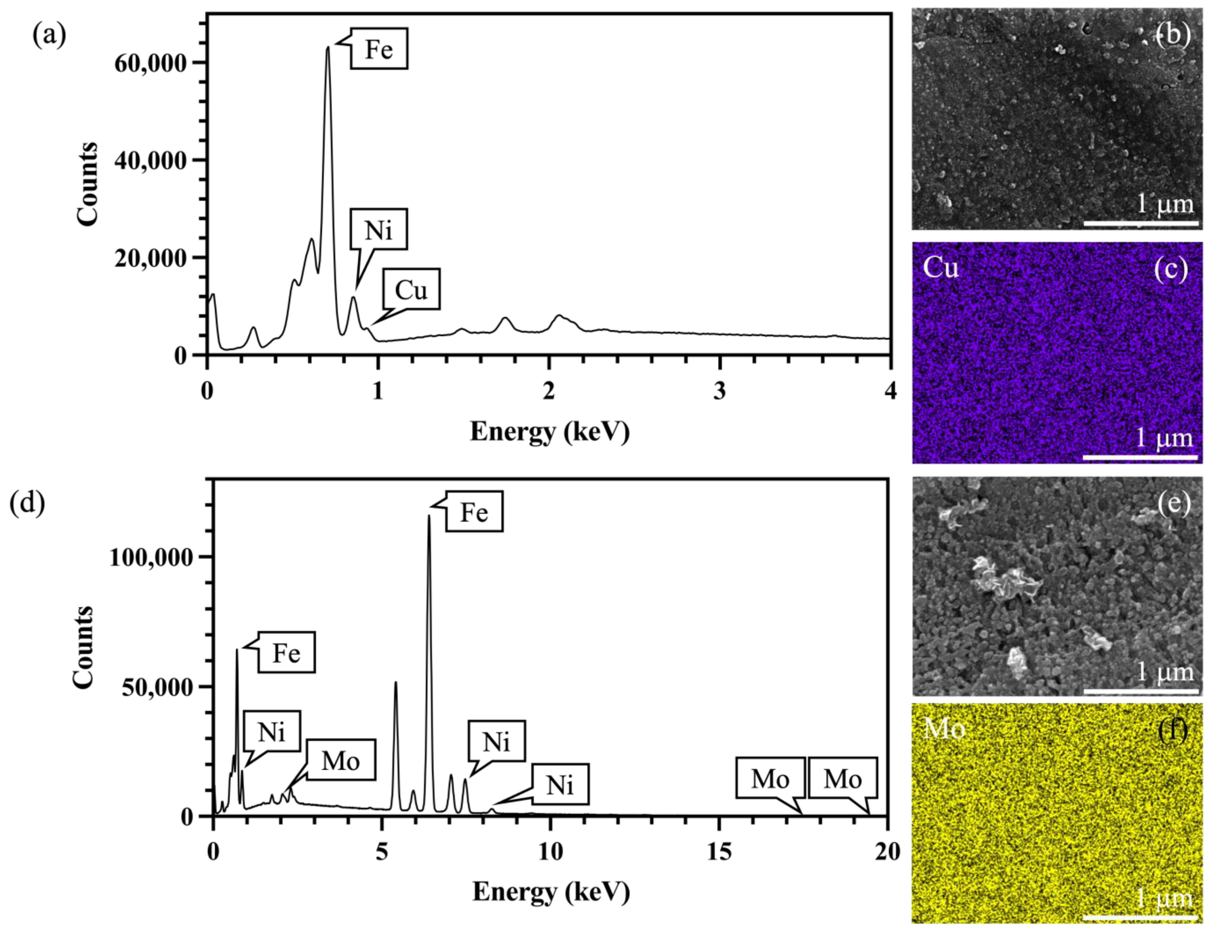
2.1. Morphological and Structural Characterization of Cathode Substrate Materials

Both carbon cloth and nickel foam are composed of single elements, whereas stainless steel meshes differ in their material composition. SEM plots of different substrate materials are presented in Figure S1. To compare the elemental composition of different stainless steel meshes, EDS and SEM (Figure 1) were conducted. The results showed that 304C stainless steel mesh (Figure 1a,b) contains copper (Cu) as an additional element compared to 316L stainless steel mesh (Figure 1c). In contrast, 316L stainless steel mesh (Figure 1d,e) contains molybdenum (Mo) as an additional element compared to 304C stainless steel mesh (Figure 1f). The presence of these transition metals contributes to enhancing hydrogen evolution performance [39].
Through electrochemical testing, the comprehensive electrochemical performance of the three substrate materials was analyzed. As shown in Figure 2a, within the scanning range, NF is the most efficient with the lowest overpotential value of 264.10 mV (vs. RHE), while CC is the least efficient with the highest overpotential value of 675.10 mV (vs. RHE). This was followed by SS of different models and mesh sizes between NF and CC, among which the 1000-mesh 316L stainless steel mesh showed the lowest hydrogen evolution overpotential at 385.00 mV (vs. RHE). The electrochemical impedance spectroscopy (EIS) data (Figure 2b) were modeled using an equivalent circuit comprising solution resistance (Rs), connected in series to a parallel arrangement of charge transfer resistance (Rct) and the constant phase element (CPE) [40]. As illustrated in Figure 2b, NF exhibited the smallest Rct value (4.84 Ω), indicative of its superior conductivity. Among various SS configurations, the 1000-mesh 316L SS demonstrated the lowest Rct (6.02 Ω), highlighting its enhanced charge transfer efficiency compared to other SS variants. CC had the largest Rct at 11.42 Ω. The results of the EIS and LSV tests for CC, NF, and SS generally followed the same trend: NF performed the best, CC performed the worst, and SS fell between the two. However, the trend varied slightly among different specifications of SS.
The double-layer capacitance (Cdl) of the substrate materials was determined by fitting the current density versus scan rate data from the CV curves (Figure S2; Table S1). A larger slope of the regression line corresponds to a larger double-layer capacitance and a greater electrochemical active surface area (ECSA). As shown in Figure 2c, NF had the largest slope, with a double-layer capacitance of 0.94 mF·cm−2. Notably, the 1000-mesh 316L stainless steel mesh also exhibited a relatively large double-layer capacitance of 0.68 mF·cm−2, close to that of NF, indicating that it also possesses a large electrochemical active surface area. As shown in Figure 2d, CC had the largest Tafel slope at 215.80 mV·dec−1, while NF had the smallest Tafel slope at 123.60 mV·dec−1. Notably, SS-316L-1000 exhibited a Tafel slope comparable to that of NF at 126.10 mV·dec−1, indicating that the 1000-mesh 316L stainless steel mesh can facilitate rapid electron transfer during the hydrogen evolution reaction, making the reaction more efficient.

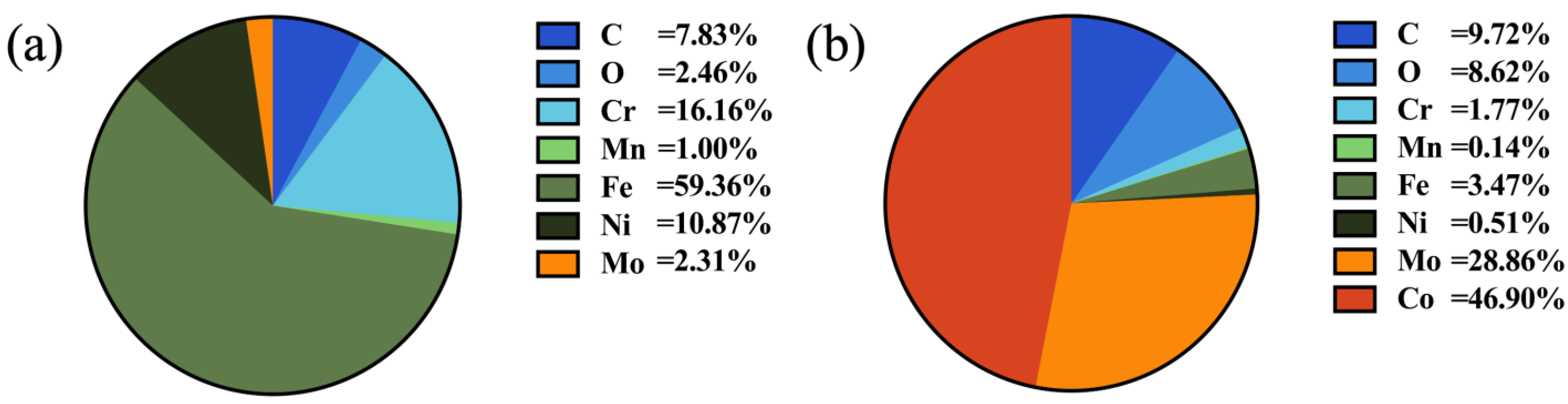
2.2. Structural Characterization of Cobalt–Molybdenum Alloy Catalyst Supported on Stainless Steel Substrate

Next, using 316L-1000 stainless steel mesh as the substrate material, a Co-Mo alloy was deposited onto the surface via electrochemical deposition to prepare the CoMo/SS cathode hydrogen evolution catalyst. Comparative SEM images of the samples before and after catalyst loading, along with photographs of the physical samples, are provided in Supplementary Materials (Figure S3). Figure 3a shows the surface elemental composition of the SS before loading, while Figure 3b shows the surface elemental composition after loading. It is evident that significant amounts of Co (46.90 Wt%) and Mo (28.86 Wt%) were successfully deposited onto the SS surface. Throughout the preparation of the composite hydrogen evolution electrode, a one-step electrodeposition method was employed, which avoided the use of binders. This approach prevented issues such as increased charge transfer resistance and blockage of active sites, thereby facilitating the subsequent hydrogen evolution.
Subsequently, XPS (as shown in Figure S4) was used to characterize the detailed electronic states of the constituent elements in the prepared Co-Mo alloy composite stainless steel mesh cathode catalyst material. As shown in Figure 4, the XPS spectra were calibrated using the C1s peak at 284.80 eV as a reference. The Co2p and Mo3d spectra of CoMo/SS were fitted to identify the optimal spin–orbit peaks and satellite peaks. In Figure 4a, the Co2p spectrum exhibits a strong main peak at 778.10 eV corresponding to Co2p3/2, and the fitted peak for Co2p1/2 has a binding energy of 793.13 eV, indicating the presence of metallic cobalt [41]. The fitted peaks for Co2+2p3/2 and Co2+2p1/2 have binding energies of 780.96 eV and 796.75 eV, respectively. The fitted peaks for Co3+2p3/2 and Co3+2p1/2 have binding energies of 782.53 eV and 798.32 eV, respectively. In Figure 4b, the fitted peak for Mo3d5/2 has a binding energy of 227.50 eV, corresponding to metallic molybdenum in the cobalt–molybdenum alloy. The fitted peaks with binding energies of 228.91 eV and 232.05 eV correspond to Mo3d5/2 and Mo3d3/2, respectively, and are attributed to Mo in the +4 oxidation state [42]. The fitted peaks for Mo6+3d5/2 and Mo6+3d3/2 have binding energies of 232.14 eV and 235.23 eV, respectively. The presence of metallic cobalt and molybdenum indicates that the cobalt and molybdenum ions in the electrolyte were successfully reduced to their zero-valent metallic states, demonstrating the effectiveness and feasibility of the electroplating method employed.

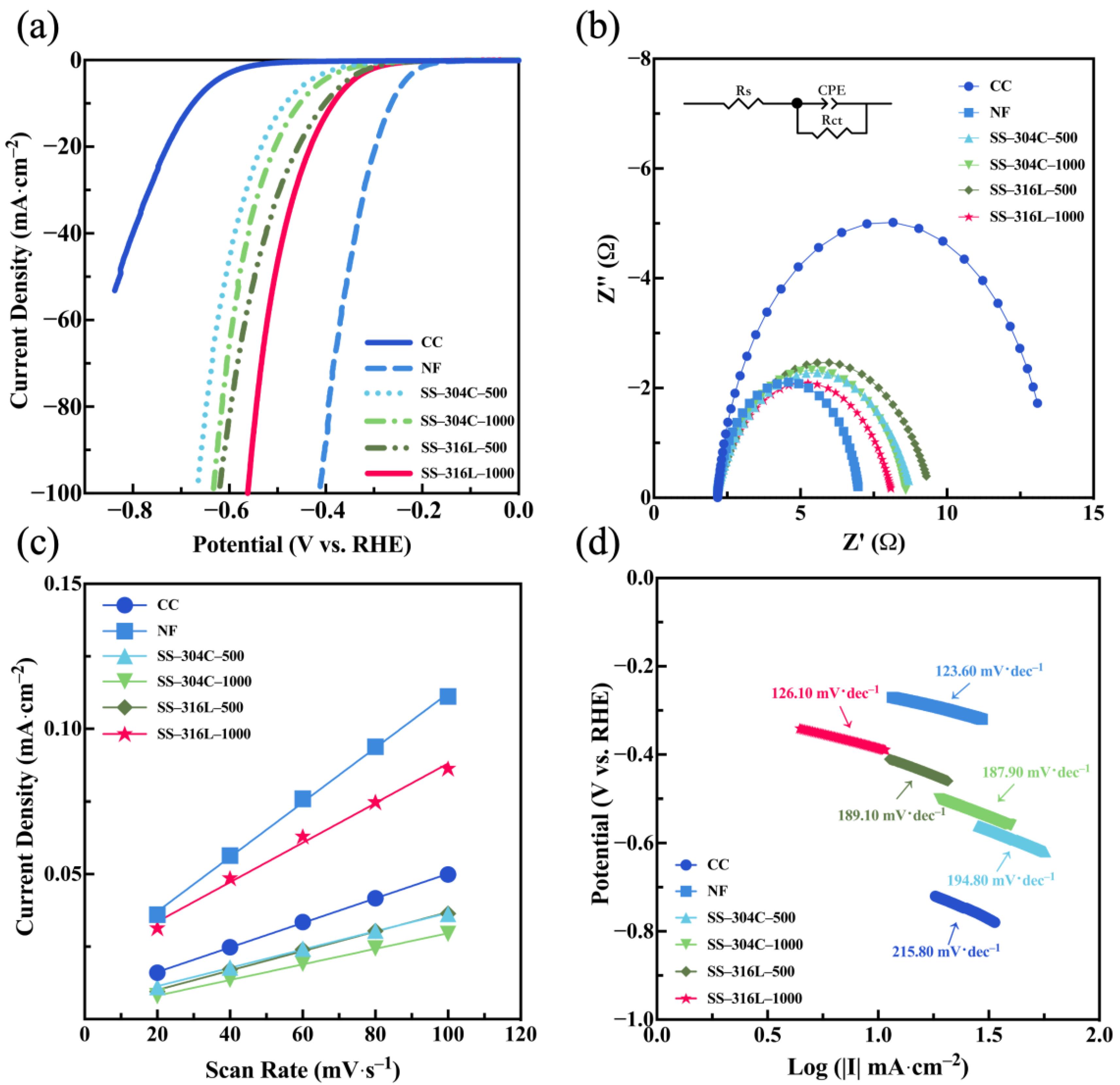
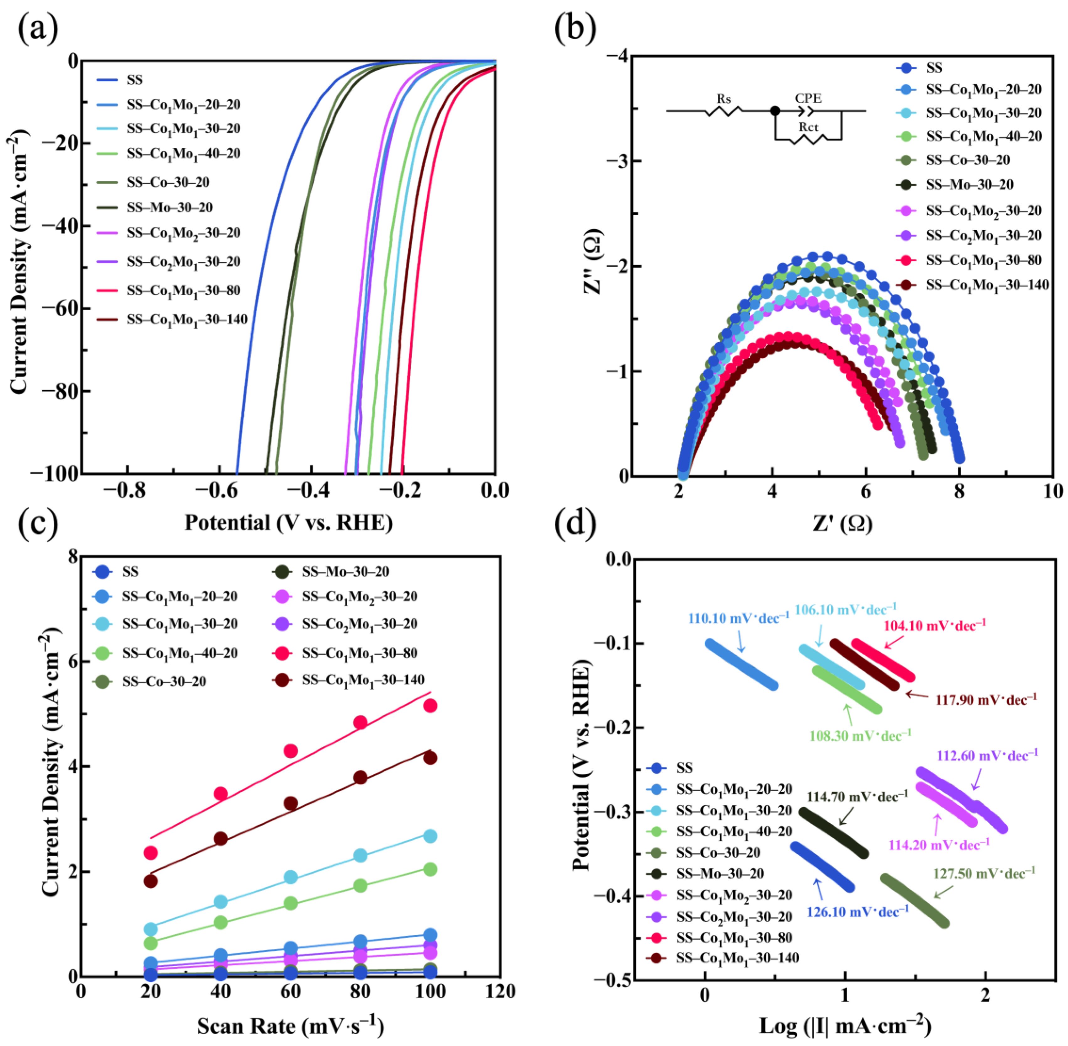
2.3. Effects of Current Density, Electroplating Time, and Cobalt-to-Molybdenum Ratio on the Electrochemical Properties of the Co-Mo Alloy

By adjusting the electrolyte composition, plating current density, and plating time, the optimal preparation method for CoMo/SS was optimized, and its electrochemical properties were tested (as shown in Figure 5 and Figures S5–S7 and Tables S2–S4). As the content of Co decreased, the hydrogen evolution performance of the catalyst also changed. From the hydrogen evolution overpotential values, it can be observed that as the Co-to-Mo ratio decreased from 1:0 to 1:1, the overpotential gradually decreased. However, when the Co content continued to decrease to zero, the overpotential of the catalyst increased. This trend was consistent with the changes in double-layer capacitance and Tafel slope. However, the EIS results showed a slightly different pattern, although the charge transfer resistance values among the samples did not differ significantly. Overall, the catalyst exhibited the best performance when the Co-to-Mo ratio in the electrolyte was 1:1.
Within the range of 20~30 mA·cm−2, the catalyst activity initially increased and then decreased. The catalyst prepared at 30 mA·cm−2 exhibited the lowest hydrogen evolution overpotential of 138.30 mV (vs. RHE), the smallest charge transfer resistance of 5.58 Ω, and the smallest Tafel slope of 106.10 mV·dec−1. Therefore, 30 mA·cm−2 was identified as the optimal plating current density.
Under the optimal current density and electrolyte composition, the relationship between plating time and catalyst performance was investigated. Three plating durations—20 min, 80 min, and 140 min—were set, and different samples were prepared for electrochemical testing. The CoMo/SS cathode catalyst prepared with an 80 min plating time exhibited the best activity. At a current density of 10 mA·cm−2, the hydrogen evolution overpotential decreased by 293.30 mV compared to the bare SS, reaching only 91.70 mV (vs. RHE). The Tafel slope of 104.10 mV·dec−1 suggests that the Volmer reaction is the rate-determining step [43], and the HER catalyzed by this electrocatalyst proceeds via the Tafel–Volmer mechanism. The charge transfer resistance also decreased. As shown in Tables S1–S4, CoMo/SS prepared under the best conditions had the largest Cdl (34.73 mF·cm−2), that is, its ECSA was the largest among all the samples. In addition, the number of active sites was determined by the electrochemical method (Figure S8). The TOF value was then obtained, where the TOF of CoMo/SS is 6.18 s−1. This indicates that CoMo/SS not only provides more catalytic sites but also reduces energy consumption during the hydrogen evolution process, improving energy conversion efficiency.
Additionally, Figure 6a shows the LSV curves of the Co-Mo alloy before and after 5000 cycles of cyclic voltammetry, and Figure 6b presents the stable long-term chronopotentiometric measurement at constant current densities of 10 and 20 mA·cm−2 for a total of 40 h. It can be observed that the overpotential at 10 mA·cm−2 changed by only 8.40 mV after 5000 cycles, demonstrating that CoMo/SS exhibits excellent stability for hydrogen evolution during long-term operation [44,45,46,47].

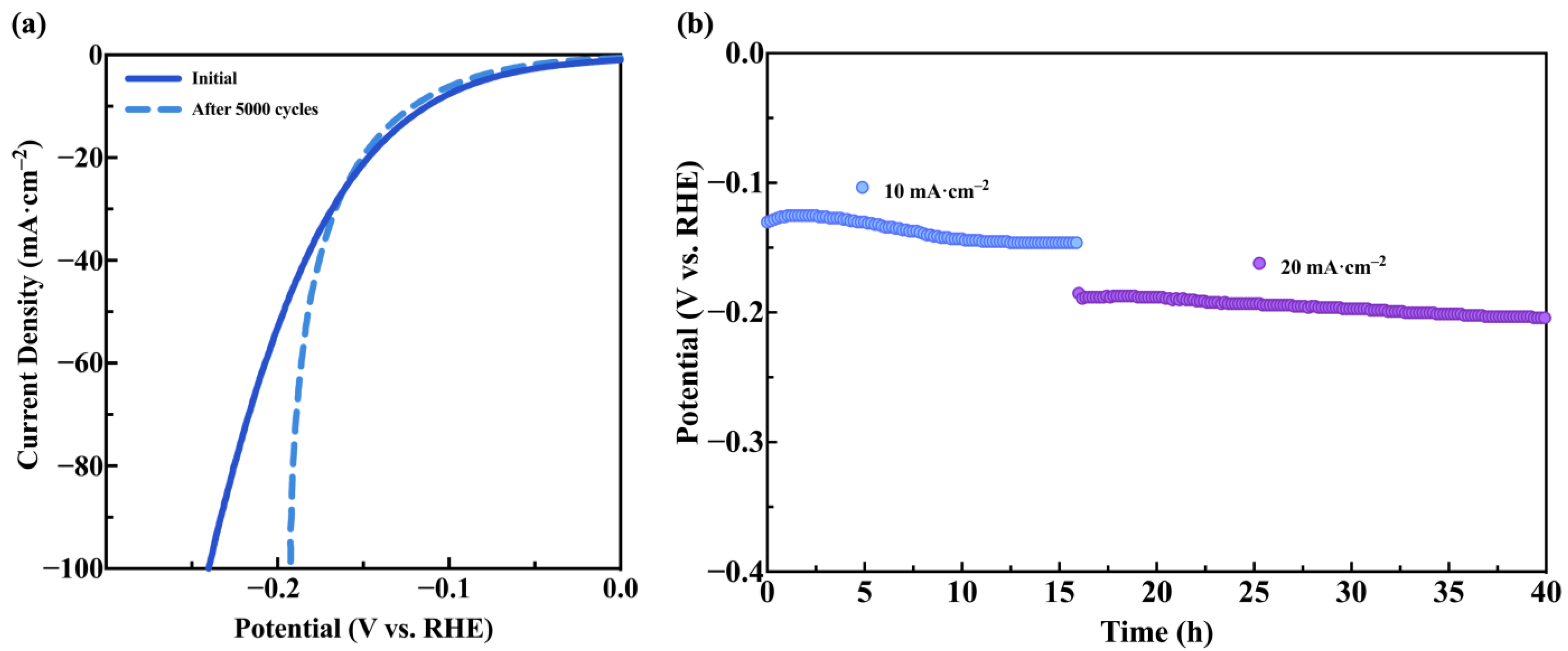
2.4. Hydrogen Production Performance of CoMo/SS Hydrogen Evolution Catalyst in MEC

Hydrogen production performance tests were conducted in a single-chamber reactor using blank SS and CoMo/SS as cathodes, with microbial-attached carbon felt as the anode. According to the gas chromatography results (Figure 7a), the hydrogen production rate of the blank SS was 0.84 m3·m−3·d−1, while the hydrogen production rate of the stainless steel mesh loaded with the cobalt–molybdenum alloy catalyst (CoMo/SS) was 1.12 m3·m−3·d−1, representing an increase of 33.33%. The sodium acetate content in the MEC nutrient solution is shown in Figure 7b. In the MEC system with blank SS as the cathode, the average consumption of sodium acetate was 0.0017 mol·d−1, whereas in the MEC system with CoMo/SS as the cathode, the average consumption of sodium acetate increased to 0.0023 mol·d−1, representing an increase of 35.29%. This indicates that CoMo/SS promotes the consumption of organic substrates during the hydrogen production process in MECs.
By calculating the coulombic efficiency of the MEC system, the energy efficiency of the system was further analyzed. As shown in Figure 7c, the coulombic efficiency for hydrogen production in the MEC system with blank SS as the cathode was 34.26%, while in the MEC system with CoMo/SS as the cathode, the coulombic efficiency reached 42.68%, representing an increase of 8.42%. This improvement, close to half of the total coulombic efficiency, demonstrates that CoMo/SS plays a significant role in reducing energy loss during the hydrogen production process in MECs.
The results obtained in this study were compared with those from significant literature, as summarized in Table 1. However, since the experiments listed in Table 1 were conducted under varying applied voltages, a precise comparison of their performance is challenging. Through comparison, the cathode material in this study still demonstrates excellent hydrogen evolution performance in MECs. At similar test voltages, the hydrogen evolution rate of CoMo/SS is three to four times higher than that of Pt/C reported by Hou et al. [48]. Among cathodes containing Mo elements, although the overall performance of CoMo/SS does not surpass that of NiMo/CC studied by Hu et al. [49], it outperforms the MoS2 material reported by Hou et al. [48] The incorporation of the Co-Mo alloy as a supported catalyst also enhances the hydrogen evolution performance of the SS material [32]. Overall, the hydrogen evolution performance of the cathode material in this study is either comparable to or superior to that of cathode materials reported in other studies [30,50,51,52].

3. Materials and Methods

3.1. Pre-Treatment of Cathode Substrate Materials

The carbon cloth (CC, ELAT Company, Los Angeles, CA, USA) was cut into 1 × 1 cm2 pieces, soaked in concentrated nitric acid at 80 °C for 5 h, then rinsed with deionized water and air-dried. The nickel foam (NF, Wuhu ErYi Material Science Co., Ltd., Wuhu, China) was cut into 1 × 1 cm2 pieces, ultrasonically treated with 3 M HCl for 15 min, rinsed with deionized water, followed by ultrasonic treatment with acetone and anhydrous ethanol (each for 15 min), and finally rinsed with deionized water and air-dried. The stainless steel mesh (SS, Anping Yangjin Wire Mesh Products Factory, Anping, China) was cut into 1 × 1 cm2 pieces, ultrasonically treated with 3 M HCl for 15 min, rinsed with deionized water, followed by ultrasonic treatment with anhydrous ethanol and deionized water (each for 15 min), and air-dried. The morphology and electrochemical performance of the substrate materials were characterized.

3.2. Preparation of CoMo/SS Catalyst

The pretreated SS was subjected to one-step electrodeposition in a 100 mL electrolytic cell at room temperature. The 1000-mesh 316L stainless steel mesh served as the working electrode, with a carbon rod and Ag/AgCl electrode as the counter and reference electrodes, respectively. The distance between the working and counter electrodes was approximately 3 cm. The electrolyte contained 25 mM Co(NO3)2·6H2O, 25 mM Na2MoO4·2H2O, and 25 g·L−1 C6H5Na3O7, with the pH adjusted to 10 using ammonia water. Electrodeposition was performed at a current density of 30 mA·cm−2 for 80 min. To determine the optimal experimental conditions, blank SS was used as a control. The hydrogen evolution performance and morphology were compared under different current densities (20 mA·cm−2, 30 mA·cm−2, 40 mA·cm−2), cobalt-to-molybdenum ratios in the electrolyte (1:0, 1:2, 1:1, 2:1, 0:1), and plating times (20 min, 80 min, 140 min).

3.3. Preparation of Microbial Anode and Construction of MEC

The microbial inoculum was obtained from anaerobic sludge in the laboratory, acclimated at 35 °C. A dual-chamber reactor was constructed by connecting an anode chamber and a cathode chamber with a 2 × 2 cm2 Nafion membrane at the interface. Carbon felt (4 × 3 × 0.5 cm3) was used as the anode material in the anode chamber for electron transfer and microbial attachment. The anode chamber was filled with a 1:4 mixture of microbial inoculum and anode nutrient solution (sodium acetate, glucose, ferrous sulfate, trace elements, and PBS solution). A platinum sheet electrode was used as the cathode material in the cathode chamber, filled with cathode solution (sodium acetate and PBS solution). The circuit was completed with a 1000 Ω resistor and copper wires. The nutrient solution was replaced every three days (60 mL each time). The voltage was monitored during acclimation, and the MEC was considered stable when the voltage showed periodic stability. After acclimation, the microbial-attached carbon felt was transferred to a two-chamber reactor as the anode, and CoMo/SS was used as the cathode for hydrogen production experiments.

3.4. Characterizations of the Cathode Materials for HER

Electrochemical tests were performed using an electrochemical workstation (CHI660E, Shanghai Chenhua Instrument Co., Ltd., Shanghai, China). A 1 × 1 cm2 sample served as the working electrode, with Ag/AgCl as the reference electrode and a carbon rod as the counter electrode. The electrolyte was 1 M KOH. The working electrode was pre-activated by cyclic voltammetry (CV) scanning from 0.00 to −1.00 V (vs. RHE) at 100 mV·s−1. Linear sweep voltammetry (LSV) for the hydrogen evolution reaction (HER) was performed from 0.10 to −1.00 V (vs. RHE) at 5 m V·s−1 to obtain the Tafel slope. Double-layer capacitance was calculated from CV tests in the non-Faradaic region at different scan rates. Electrochemical impedance spectroscopy (EIS) was conducted in the frequency range of 10−2 to 105 Hz, and the spectra were fitted using Zview (version3.3) software to evaluate charge transfer resistance. Stability was assessed by comparing LSV curves before and after 5000 cycles of CV scanning from 0.00 to −1.00 V (vs. RHE) and chronopotentiometric measurement at constant current densities of 10 and 20 mA·cm−2. The cathode materials were observed using a scanning electron microscope (SEM, acceleration voltage of 3.00 kV, SU8600, Hitachi, Tokyo, Japan). The elemental composition was analyzed using energy-dispersive X-ray spectroscopy (EDS, SU8600, Hitachi, Japan). The valence states of the elements in the catalyst were determined using X-ray photoelectron spectroscopy (XPS, 1361 eV, K-Alpha, Thermo Fisher Scientific, Waltham, MA, USA).

3.5. Evaluation of Hydrogen Production Performance in MEC

Gas produced in the single-chamber reactor was collected and analyzed by gas chromatography to determine hydrogen content and production rate. The nutrient solution was analyzed by liquid chromatography before and after each replacement to calculate substrate consumption and hydrogen conversion rate. Coulombic efficiency (CE), also known as current efficiency, was calculated using Equation (1) to evaluate the efficiency of electron-to-hydrogen conversion [53]:
C E = C p i C t = F b p i n p i t 0 t I d t
where CE is coulombic efficiency (%), b is molar conversion coefficient of the product (2 eq·mol−1 for hydrogen), Cpi is number of electrons in the product (Cp = Fbn), Ct is total electrons consumed (obtained from the current-time curve), F is Faraday’s constant (96,485 C·mol−1), and n is moles of the product.

4. Conclusions

In this study, three commonly used substrate materials in MEC—carbon cloth, nickel foam, and stainless steel mesh—were systematically compared for their electrochemical performance. Based on practical cost considerations, 316L stainless steel mesh was ultimately selected as the cathode substrate. When the ratio of Co-to-Mo in the plating solution was 1:1 and electroplating time was 80 min at 30 mA·cm−2 current density, a transition metal Co-Mo alloy catalyst (CoMo/SS) was subsequently deposited onto the stainless steel surface via electrodeposition. Experimental results demonstrate that the catalyst loading significantly improves the hydrogen evolution performance of the stainless steel substrate, not only enhancing its kinetic activity but also ensuring excellent stability. In practical MEC applications, the CoMo/SS system achieved a hydrogen production rate of 1.12 m3·m−3·d−1 when using sodium acetate as a solution. This study employed a simple one-step electrodeposition method to synthesize a Co-Mo alloy catalyst deposited onto a stainless steel mesh substrate. This approach not only offers a cost-effective strategy for hydrogen evolution catalysts but also provides critical insights for optimizing the performance of MEC cathode materials.

Supplementary Materials

The following supporting information can be downloaded at: https://www.mdpi.com/article/10.3390/catal15050439/s1, Figure S1: SEM images of cathode substrate materials: (a) carbon cloth; (b) nickel foam; (c) 500-mesh stainless steel mesh; (d) 1000-mesh stainless steel mesh; Figure S2: Cyclic voltametric curves of (a) CC, (b) NF, (c) SS-304C-500, (d) SS-304C-1000, (e) SS-316L-500, (f) SS-316L-1000 in 1 mol·L−1 KOH; Figure S3: SEM images of composite catalyst (a) before and (b) after; sample diagram of CoMo/SS; Figure S4: The XPS survey spectrum of CoMo/SS; Figure S5: Cyclic voltametric curves of different current density in 1 mol·L−1 KOH: (a) blank SS, (b) 20 mA·cm−2, (c) 30 mA·cm−2, (d) 40 mA·cm−2; Figure S6: Cyclic voltametric curves of Co-to-Mo ratio in 1 mol·L−1 KOH: (a) blank SS, (b) 1:0, (c) 1:2, (d) 1:1, (e) 2:1, (f) 0:1; Figure S7: Cyclic voltametric curves of different electroplating time in 1 mol·L−1 KOH: (a) blank SS, (b) 20 min, (c) 80 min, (d) 140 min; Figure S8: Cyclic voltametric curves for SS and CoMo/SS recorded between −0.2 V and 0.5 V in 1 M PBS (pH=7) at a scan rate of 50 mV·S−1. Table S1: Comparison of double-layer capacitance and ECSA of different cathode substrate materials; Table S2: Comparison of double-layer capacitance and ECSA of cathode materials prepared at different current densities; Table S3: Comparison of double-layer capacitance and ECSA of cathode materials prepared with different Co-to-Mo ratios; Table S4: Comparison of double-layer capacitance and ECSA of cathode materials prepared at different electroplating times.

Author Contributions

Data curation: G.L.; formal analysis: G.L.; funding acquisition: Y.W., H.S. and G.X.; investigation: G.L.; methodology: G.L. and Y.W.; project administration: H.S.; supervision: H.S.; visualization: G.L.; writing—original draft: G.L.; writing—review and editing: H.S., G.X. and Y.W. All authors have read and agreed to the published version of the manuscript.

Funding

This research was funded by the National Natural Science Foundation of China (22408378, 22408019) and the Fundamental Research Funds for the Central Universities (PY2517).

Data Availability Statement

The data are contained within the article.

Conflicts of Interest

The authors declare no conflicts of interest.

References

  1. Poudyal, L.; Adhikari, K. Environmental Sustainability in Cement Industry: An Integrated Approach for Green and Economical Cement Production. Resour. Environ. Sustain. 2021, 4, 100024. [Google Scholar] [CrossRef]
  2. Xu, H.; Jia, Y.; Sun, Z.; Su, J.; Liu, Q.S.; Zhou, Q.; Jiang, G. Environmental Pollution, a Hidden Culprit for Health Issues. EEH 2022, 1, 31–45. [Google Scholar] [CrossRef] [PubMed]
  3. Zheng, Y.; Jiao, Y.; Qiao, S.Z. Engineering of Carbon-Based Electrocatalysts for Emerging Energy Conversion: From Fundamentality to Functionality. Adv. Mater. 2015, 27, 5372–5378. [Google Scholar] [CrossRef] [PubMed]
  4. Zhu, W.; Michalsky, R.; Metin, Ö.; Lv, H.; Guo, S.; Wright, C.J.; Sun, X.; Peterson, A.A.; Sun, S. Monodisperse Au Nanoparticles for Selective Electrocatalytic Reduction of CO2 to CO. J. Am. Chem. Soc. 2013, 135, 16833–16836. [Google Scholar] [CrossRef]
  5. Zhao, Q.; Yu, P.; Mahendran, R.; Huang, W.; Gao, Y.; Yang, Z.; Ye, T.; Wen, B.; Wu, Y.; Li, S.; et al. Global Climate Change and Human Health: Pathways and Possible Solutions. Eco-Environ. Health 2022, 1, 53–62. [Google Scholar] [CrossRef] [PubMed]
  6. Zhang, J.; Gao, W.; Yue, Y.; Wang, W.; Tan, F.; Wang, X.; Qiao, X.; Wong, P.K. Two-Step Assembly Induced Fe0-Anchored Graphitic N-Rich Graphene with Biactive Centers for Enhanced Heterogeneous Peroxymonosulfate Activation. J. Mater. Chem. A 2021, 9, 17366–17379. [Google Scholar] [CrossRef]
  7. Zhang, J.; Chen, P.; Gao, W.; Wang, W.; Tan, F.; Wang, X.; Qiao, X.; Wong, P.K. Melamine-Cyanurate Supramolecule Induced Graphitic N-Rich Graphene for Singlet Oxygen-Dominated Peroxymonosulfate Activation to Efficiently Degrade Organic Pollutants. Sep. Purif. Technol. 2021, 265, 118474. [Google Scholar] [CrossRef]
  8. IEA. CO2 Emissions in 2023. 2023. Available online: https://www.iea.org/reports/co2-emissions-in-2023 (accessed on 1 June 2024).
  9. IEA. World Energy Outlook 2023. 2024. Available online: https://www.iea.org/reports/world-energy-outlook-2024 (accessed on 1 June 2024).
  10. Kim, Y.K.; Seo, H.-J.; Kim, S.; Hwang, S.-H.; Park, H.; Lim, S.K. Effect of ZnO Electrodeposited on Carbon Film and Decorated with Metal Nanoparticles for Solar Hydrogen Production. J. Mater. Sci. Technol. 2016, 32, 1059–1065. [Google Scholar] [CrossRef]
  11. Wang, L.; Al-Mamun, M.; Liu, P.; Zhong, Y.L.; Wang, Y.; Yang, H.G.; Zhao, H. Enhanced Thermochemical H2 Production on Ca-Doped Lanthanum Manganite Perovskites Through Optimizing the Dopant Level and Re-Oxidation Temperature. Acta Metall. Sin. (Engl. Lett.) 2018, 31, 431–439. [Google Scholar] [CrossRef]
  12. Li, J.; Fu, G.; Sheng, X.; Li, G.; Chen, H.; Shu, K.; Dong, Y.; Wang, T.; Deng, Y. A Comprehensive Review on Catalysts for Seawater Electrolysis. Adv. Powder Mater. 2024, 3, 100227. [Google Scholar] [CrossRef]
  13. Hosseini, S.E.; Wahid, M.A. Hydrogen Production from Renewable and Sustainable Energy Resources: Promising Green Energy Carrier for Clean Development. Renew. Sustain. Energy Rev. 2016, 57, 850–866. [Google Scholar] [CrossRef]
  14. Das, D.; Khanna, N.; Veziroğlu, N. Recent Developments in Biological Hydrogen Production Processes. Chem. Ind. Chem. Eng. Q. 2008, 14, 57–67. [Google Scholar] [CrossRef]
  15. Zhang, Y.; Shen, J. Enhancement Effect of Gold Nanoparticles on Biohydrogen Production from Artificial Wastewater. Int. J. Hydrogen Energy 2007, 32, 17–23. [Google Scholar] [CrossRef]
  16. Ramsurn, H.; Gupta, R.B. Nanotechnology in Solar and Biofuels. ACS Sustain. Chem. Eng. 2013, 1, 779–797. [Google Scholar] [CrossRef]
  17. Zhu, H.; Seto, P.; Parker, W.J. Enhanced Dark Fermentative Hydrogen Production under the Effect of Zero-Valent Iron Shavings. Int. J. Hydrogen Energy 2014, 39, 19331–19336. [Google Scholar] [CrossRef]
  18. Liu, Y.; Zhang, Y.; Quan, X.; Li, Y.; Zhao, Z.; Meng, X.; Chen, S. Optimization of Anaerobic Acidogenesis by Adding Fe0 Powder to Enhance Anaerobic Wastewater Treatment. J. Chem. Eng. 2012, 192, 179–185. [Google Scholar] [CrossRef]
  19. Liu, Y.; Zhang, Y.; Zhao, Z.; Li, Y.; Quan, X.; Chen, S. Enhanced Azo Dye Wastewater Treatment in a Two-Stage Anaerobic System with Fe0 Dosing. Bioresour. Technol. 2012, 121, 148–153. [Google Scholar] [CrossRef]
  20. Dai, H.-Y.; Yang, H.-M.; Liu, X.; Song, X.-L.; Liang, Z.-H. Hydrogen Production Using “Direct-Starting” Biocathode Microbial Electrolysis Cell and the Analysis of Microbial Communities. Acta Metall. Sin. (Engl. Lett.) 2019, 32, 297–304. [Google Scholar] [CrossRef]
  21. Fu, Q.; Kobayashi, H.; Kuramochi, Y.; Xu, J.; Wakayama, T.; Maeda, H.; Sato, K. Bioelectrochemical Analyses of a Thermophilic Biocathode Catalyzing Sustainable Hydrogen Production. Int. J. Hydrogen Energy 2013, 38, 15638–15645. [Google Scholar] [CrossRef]
  22. Noori, M.T.; Rossi, R.; Logan, B.E.; Min, B. Hydrogen Production in Microbial Electrolysis Cells with Biocathodes. Trends Biotechnol. 2024, 42, 815–828. [Google Scholar] [CrossRef]
  23. Chai, Y.; Lyu, Z.; Du, H.; Li, P.; Ding, S.; Jiang, Y.; Wang, H.; Min, Q.; Du, D.; Lin, Y.; et al. Recent Progress on Rational Design of Catalysts for Fermentative Hydrogen Production. SusMat 2022, 2, 392–410. [Google Scholar] [CrossRef]
  24. Jafary, T.; Wan Daud, W.R.; Ghasemi, M.; Abu Bakar, M.H.; Sedighi, M.; Kim, B.H.; Carmona-Martínez, A.A.; Jahim, J.M.; Ismail, M. Clean Hydrogen Production in a Full Biological Microbial Electrolysis Cell. Int. J. Hydrogen Energy 2019, 44, 30524–30531. [Google Scholar] [CrossRef]
  25. Rathinam, N.K.; Bibra, M.; Salem, D.R.; Sani, R.K. Thermophiles for Biohydrogen Production in Microbial Electrolytic Cells. Bioresour. Technol. 2019, 277, 171–178. [Google Scholar] [CrossRef]
  26. Swaminathan, P.; Ghosh, A.; Sunantha, G.; Sivagami, K.; Mohanakrishna, G.; Aishwarya, S.; Shah, S.; Sethumadhavan, A.; Ranjan, P.; Prajapat, R. A Comprehensive Review of Microbial Electrolysis Cells: Integrated for Wastewater Treatment and Hydrogen Generation. Process Saf. Environ. Prot. 2024, 190, 458–474. [Google Scholar] [CrossRef]
  27. Zhong, L.; Ma, Y.; Li, T.; Bo, X.; Wang, J.; Chang, Y.; Li, P.; Zhao, Y. The influence of different layers of carbon paper on the electricity generation in MFC. New Chem. Mater. 2015, 03, 132–135. [Google Scholar]
  28. Liu, C.; Liu, L.; Duan, X. Electricity generation of MFCs with graphite fiber brush and carbon cloth anode. J. Power Sources 2015, 39, 1661–1663. [Google Scholar]
  29. Bo, X.; Li, P.; Zhao, X.; Wang, J.; Li, J.; Pei, X.; Zhao, Y. Research on producing electricity characteristics of wastewater microbial fuel cell anode carbon felt. New Chem. Mater. 2014, 042, 126–129. [Google Scholar]
  30. Selembo, P.A.; Merrill, M.D.; Logan, B.E. Hydrogen Production with Nickel Powder Cathode Catalysts in Microbial Electrolysis Cells. Int. J. Hydrogen Energy 2010, 35, 428–437. [Google Scholar] [CrossRef]
  31. Zhao, Y.; Dong, Z.; Wang, Y.; Li, J.; An, X.; Yang, D. Process Kinetics for the Electrocatalytic Hydrogen Evolution Reaction on Carbon-Based Ni/NiO Nanocomposite in a Single-Chamber Microbial Electrolysis Cell. Int. J. Hydrogen Energy 2019, 44, 28841–28847. [Google Scholar] [CrossRef]
  32. Selembo, P.A.; Merrill, M.D.; Logan, B.E. The Use of Stainless Steel and Nickel Alloys as Low-Cost Cathodes in Microbial Electrolysis Cells. J. Power Sources 2009, 190, 271–278. [Google Scholar] [CrossRef]
  33. Munoz, L.D.; Erable, B.; Etcheverry, L.; Riess, J.; Basséguy, R.; Bergel, A. Combining Phosphate Species and Stainless Steel Cathode to Enhance Hydrogen Evolution in Microbial Electrolysis Cell (MEC). Electrochem. Commun. 2010, 12, 183–186. [Google Scholar] [CrossRef]
  34. Su, M.; Wei, L.; Qiu, Z.; Wang, G.; Shen, J. Hydrogen Production in Single Chamber Microbial Electrolysis Cells with Stainless Steel Fiber Felt Cathodes. J. Power Sources 2016, 301, 29–34. [Google Scholar] [CrossRef]
  35. Logan, B.E.; Call, D.; Cheng, S.; Hamelers, H.V.M.; Sleutels, T.H.J.A.; Jeremiasse, A.W.; Rozendal, R.A. Microbial Electrolysis Cells for High Yield Hydrogen Gas Production from Organic Matter. Environ. Sci. Technol. 2008, 42, 8630–8640. [Google Scholar] [CrossRef]
  36. Perona-Vico, E.; Feliu-Paradeda, L.; Puig, S.; Bañeras, L. Bacteria Coated Cathodes as an In-Situ Hydrogen Evolving Platform for Microbial Electrosynthesis. Sci. Rep. 2020, 10, 19852. [Google Scholar] [CrossRef] [PubMed]
  37. Kundu, A.; Sahu, J.N.; Redzwan, G.; Hashim, M.A. An Overview of Cathode Material and Catalysts Suitable for Generating Hydrogen in Microbial Electrolysis Cell. Int. J. Hydrogen Energy 2013, 38, 1745–1757. [Google Scholar] [CrossRef]
  38. Wang, C.; Song, Z.; Ni, J.; Pan, Z.; Huang, G. Progress of electrocatalytic hydrogen evolution reaction catalysts. Chem. Eng. Prog. 2021, 40, 5523–5534. [Google Scholar] [CrossRef]
  39. Conway, B.E.; Jerkiewicz, G. Relation of Energies and Coverages of Underpotential and Overpotential Deposited H at Pt and Other Metals to the ‘Volcano Curve’ for Cathodic H2 Evolution Kinetics. Electrochim. Acta 2000, 45, 4075–4083. [Google Scholar] [CrossRef]
  40. Wang, X.; Zhang, K.; Xie, Y.; Yu, D.; Tian, H.; Lou, Y. MnOxHy-Modified CoMoP/NF Nanosheet Arrays as Hydrogen Evolution Reaction and Oxygen Evolution Reaction Bifunctional Catalysts under Alkaline Conditions. Dalton Trans. 2023, 52, 15091–15100. [Google Scholar] [CrossRef]
  41. Yang, Y.; Zeng, R.; Xiong, Y.; DiSalvo, F.J.; Abruña, H.D. Cobalt-Based Nitride-Core Oxide-Shell Oxygen Reduction Electrocatalysts. J. Am. Chem. Soc. 2019, 141, 19241–19245. [Google Scholar] [CrossRef]
  42. Zhao, K.; Sun, W.; Zhang, X.; Meng, J.; Zhong, M.; Qiang, L.; Liu, M.-J.; Gu, B.-N.; Chung, C.-C.; Liu, M.; et al. High-Performance and Long-Cycle Life of Triboelectric Nanogenerator Using PVC/MoS2 Composite Membranes for Wind Energy Scavenging Application. Nano Energy 2022, 91, 106649. [Google Scholar] [CrossRef]
  43. Shi, Y.; Zhang, B. Recent Advances in Transition Metal Phosphide Nanomaterials: Synthesis and Applications in Hydrogen Evolution Reaction. Chem. Soc. Rev. 2016, 45, 1529–1541. [Google Scholar] [CrossRef] [PubMed]
  44. Zhang, X.; Zhou, F.; Pan, W.; Liang, Y.; Wang, R. General Construction of Molybdenum-Based Nanowire Arrays for pH-Universal Hydrogen Evolution Electrocatalysis. Adv. Funct. Mater. 2018, 28, 1804600. [Google Scholar] [CrossRef]
  45. Yang, G.; Yang, T.; Wang, Z.; Wang, K.; Zhang, M.; Lund, P.D.; Yun, S. Targeted Doping Induces Interfacial Orientation for Constructing Surface-Functionalized Schottky Junctions to Coordinate Redox Reactions in Water Electrolysis. Adv. Powder Mater. 2024, 3, 100224. [Google Scholar] [CrossRef]
  46. Chen, Y.; Zhang, Y.; Zhang, X.; Tang, T.; Luo, H.; Niu, S.; Dai, Z.; Wan, L.; Hu, J. Self-Templated Fabrication of MoNi4/MoO3-x Nanorod Arrays with Dual Active Components for Highly Efficient Hydrogen Evolution. Adv. Mat. 2017, 29, 1703311. [Google Scholar] [CrossRef]
  47. Wu, L.; Yu, L.; Zhang, F.; McElhenny, B.; Luo, D.; Karim, A.; Chen, S.; Ren, Z. Heterogeneous Bimetallic Phosphide Ni2P-Fe2P as an Efficient Bifunctional Catalyst for Water/Seawater Splitting. Adv. Funct. Mater. 2021, 31, 2006484. [Google Scholar] [CrossRef]
  48. Hou, Y.; Zhang, B.; Wen, Z.; Cui, S.; Guo, X.; He, Z.; Chen, J. A 3D Hybrid of Layered MoS2/Nitrogen-Doped Graphene Nanosheet Aerogels: An Effective Catalyst for Hydrogen Evolution in Microbial Electrolysis Cells. J. Mater. Chem. A 2014, 2, 13795–13800. [Google Scholar] [CrossRef]
  49. Hu, H.; Fan, Y.; Liu, H. Hydrogen Production in Single-Chamber Tubular Microbial Electrolysis Cells Using Non-Precious-Metal Catalysts. Int. J. Hydrogen Energy 2009, 34, 8535–8542. [Google Scholar] [CrossRef]
  50. Huang, Y.-X.; Liu, X.-W.; Sun, X.-F.; Sheng, G.-P.; Zhang, Y.-Y.; Yan, G.-M.; Wang, S.-G.; Xu, A.-W.; Yu, H.-Q. A New Cathodic Electrode Deposit with Palladium Nanoparticles for Cost-Effective Hydrogen Production in a Microbial Electrolysis Cell. Int. J. Hydrogen Energy 2011, 36, 2773–2776. [Google Scholar] [CrossRef]
  51. Liang, D.; Zhang, L.; He, W.; Li, C.; Liu, J.; Liu, S.; Lee, H.-S.; Feng, Y. Efficient Hydrogen Recovery with CoP-NF as Cathode in Microbial Electrolysis Cells. Appl. Energy 2020, 264, 114700. [Google Scholar] [CrossRef]
  52. Jeremiasse, A.W.; Hamelers, H.V.M.; Buisman, C.J.N. Microbial Electrolysis Cell with a Microbial Biocathode. Bioelectrochemistry 2010, 78, 39–43. [Google Scholar] [CrossRef]
  53. Qi, Y.; Arnaud, B.; Elie, D.L.Q.; Lv, F.; He, P.; Théodore, B. Selective inhibition of methanogens using 2-bromoethanesulfonate for improvement of acetate production from CO2 in bioelectrochemical systems. CIESC J. 2016, 5, 2033–2040. [Google Scholar] [CrossRef]
Figure 1. (a) EDS spectra, (b) SEM image, (c) EDS layered image of Cu for SS-304C; (d) EDS spectra, (e) SEM image, (f) EDS layered image of Mo for SS-316L.
Catalysts 15 00439 g001
Figure 2. (a) LSV, (b) EIS, (c) current density versus scan rate for different material composite electrodes, and (d) Tafel slopes of different materials (material–model–mesh) in 1 mol·L−1 KOH.
Catalysts 15 00439 g002
Figure 3. Pie charts of elements content of (a) SS and (b) CoMo/SS.
Catalysts 15 00439 g003
Figure 4. XPS spectra of CoMo/SS: (a) Co2p high-resolution spectra; (b) Mo3d high-resolution spectra.
Catalysts 15 00439 g004
Figure 5. (a) LSV, (b) EIS, (c) current density versus scan rate for different material composite electrodes, and (d) Tafel slopes of different materials (SS-element ratio–current density–current time) in 1 mol·L−1 KOH.
Catalysts 15 00439 g005
Figure 6. (a) HER LSV curves of CoMo/SS before and after 5000 CV cycles; (b) chronopotentiometric curve of CoMo/SS at constant current densities of 10 and 20 mA·cm−2 for HER in 1 mol·L−1 KOH.
Catalysts 15 00439 g006
Figure 7. (a) Rates of hydrogen production; (b) sodium acetate consumption and hydrogen production; (c) hydrogen coulombic efficiency for SS and CoMo/SS.
Catalysts 15 00439 g007
Table 1. The performances comparisons of different cathodes used in MEC.
CathodeEep (V)Q (m3·m−3·d−1)CE (%)Ref.
Pt/C0.80.31 ± 0.0221.34 ± 0.87[48]
Pd/CC0.62.6 ± 0.5 L·m−2·d−156.0 ± 10.2[50]
Ni 2100.61.3 ± 0.392.7 ± 15.8[30]
NiW/CC0.61.573[49]
NiMo/CC0.62.075[49]
CoP-NF0.70.22 ± 0.0287 ± 10.2[51]
3D MoS2/N-GAs0.80.1924.28 ± 0.49[48]
Biocathode0.80.03~0.04-[52]
SS 304 mesh0.90.59 ± 0.01-[32]
SS 316L mesh0.90.8434.26This study
CoMo/SS0.91.1242.68This study
Note: Eep, cell equivalent potential; Q, hydrogen production rate, CE: coulombic efficiency.
Disclaimer/Publisher’s Note: The statements, opinions and data contained in all publications are solely those of the individual author(s) and contributor(s) and not of MDPI and/or the editor(s). MDPI and/or the editor(s) disclaim responsibility for any injury to people or property resulting from any ideas, methods, instructions or products referred to in the content.

