Article

Novel Ni/SBA-15 Catalyst Pellets for Tar Catalytic Cracking in a Dried Sewage Sludge Pyrolysis Pilot Plant

1
School of Science, Engineering & Design, Teesside University, Middlesbrough TS1 3BX, UK
2
UNICAT Catalysts Technologies, LLC, 5918 South Highway 35, Alvin, TX 77511, USA
3
Clariant Qatar W.L.L., Mesaieed Industrial City P.O. Box 50240, Qatar
4
Graduate School of Frontier Sciences, The University of Tokyo, Kashiwa 277-8561, Japan
*
Author to whom correspondence should be addressed.
Catalysts 2025, 15(2), 142; https://doi.org/10.3390/catal15020142
Submission received: 30 December 2024 / Revised: 19 January 2025 / Accepted: 29 January 2025 / Published: 3 February 2025
(This article belongs to the Section Catalysis for Sustainable Energy)

Abstract

:
Novel Ni/SBA-15 catalysts were synthesised and their activity in the dry reforming of methane process was assessed. These materials were prepared into extrudates shaped like pellets and tested in a pyrolysis pilot plant fitted with a catalytic reactor for sewage sludge pyrolysis tar removal. The Ni/SBA-15 catalyst pellets remained highly active and stable throughout the test’s duration, converting 100% tar in the hot gas to smaller non-condensable gases, thereby increasing the pyrolysis gas fraction and eliminating the problematic tar in the vapour stream. Catalyst characterisation with Scanning Electron Microscopy (SEM), Energy-Dispersive X-ray (EDX) analysis, Transmission Electron Microscopy (TEM), and Thermogravimetric Analysis (TGA) confirmed that both the Ni/SBA-15-powered catalyst and the pellets were resistant to sintering and carbon deposition and remained highly active even with relatively high-level sulphur in the feed stream. The Ni/SBA-15 catalyst extrudates were prepared by mixing the powdered catalyst with varied amounts of colloidal silica binder and fixed amounts of methyl cellulose and water. The highest mechanical strength of the extrudates was determined to be of those obtained with 36% of the inorganic binder. The physical properties and catalytic activity of Ni/SBA-15 pellets with 36% colloidal silica were compared with the original powdered Ni/SBA-15 catalyst to assess the binder inhibitory effect, if any. The results confirmed that colloidal silica binder did not inhibit the desired catalyst properties and performance in the reaction. Instead, enhanced catalytic performance was observed.

1. Introduction

As urban populations continue to grow, wastewater treatment plants across the globe are facing greater challenges in the management and disposal of their increasing sewage sludge—a solid residue with about 60–70% organic content, in addition to some inorganic materials and heavy metals produced after wastewater treatment from their facilities. More stringent government legislation to protect the environment from exposure to hazardous waste means that water treatment plants will have to operate more efficient waste management systems. For instance, the European Union Urban Waste Water Directive 91/271/EEC, which was amended by 98/15/EC, completely phased out the dumping of sewage sludge into the sea and other water bodies by member countries, via ships, pipelines, or by any other means [1]. There has also been a significant reduction in the EU in the emission of dioxins permitted by incineration. Disposal of sewage sludge in landfills is capital intensive and studies show that many landfill sites release uncontrolled methane, a prominent greenhouse gas, into the atmosphere which causes wild land fires and global warming [2,3,4,5,6].
The legal framework to treat and manage waste in the EU is the Waste Framework Directive, which establishes a five-step waste hierarchy, ranging from prevention, as the preferred option, to landfill disposal, as the last resort, to comply with the 5Rs of sustainability, i.e., record, report, reduce, recycle, and reuse. However, sustainability is not a challenge only for the EU to address. It is a global challenge, which must be addressed in a concerted way to create a healthier planet. In this respect, the 5Rs Sustainability Framework is a powerful, comprehensive, and integrated framework, adopted by many organisations and governments when defining their sustainability and ESG strategies. The 5Rs Sustainability Framework is supported by several international and national sustainability standards and regulations, including the United Nations’ Sustainable Development Goals (SDGs).
The European Union’s response to the waste management challenge is demonstrated in its target to reduce waste disposal by 50% by 2050 through waste recovery reuse, recycling, and energy recovery in addition to other measures, and it strongly recommends thermochemical waste conversion by pyrolysis/gasification to energy production as a potentially sustainable route to manage waste disposal [7].
Pyrolysis is the irreversible thermochemical decomposition of organic materials at temperatures between 300 and 900 °C in the absence of oxygen or air, where large complex hydrocarbon molecules of the organic matter break down to smaller and simple molecules of gas, liquid, and solid [8,9]. Gasification is also a process of thermochemical decomposition of organic materials but one that occurs in the presence of oxygen or air [10,11,12]. The major advantage of pyrolysis over gasification is that pyrolysis, unlike gasification, does not produce highly toxic gases such as furans and dioxins because the oxygen required for their formation is absent in pyrolysis [13].
Dried sewage sludge has a much higher heating value (12,000–20,000 kJ/kg) compared to wet sewage sludge (1000–3000 kJ/kg), and so, the sludge is usually dried before pyrolysis [14].
The gas fraction from the pyrolysis of organic matter contains non condensable gases, mainly hydrogen, methane, carbon monoxide, carbon dioxide, and some low molecular weight hydrocarbons. The liquid fraction contains water and condensable low-grade bio-oil, also referred to as tar, which consists of many complex organic compounds such as aliphatic compounds, mono-aromatic compounds, polycyclic aromatic hydrocarbons (PAHs), oxygenated hydrocarbons, organo-nitrogen compounds, etc. The solid portion contains char and ash with heavy metals present [15,16,17,18,19]. The distribution of gases, liquids and solids depends on the nature of biomass and the operating conditions used in pyrolysis, especially temperature, heating rates, and residence time in the reactor. For instance, higher temperatures and longer residence time in the reactor maximise gas production, while lower temperatures and shorter residence time in the reactor maximise solid formation. Flash pyrolysis, where the organic matter is quickly heated between 350–500 °C in 2 s, maximises oil production [20,21,22,23,24,25].
Many researchers have tried to upgrade the oil from the pyrolysis of sewage sludge to high quality bio-crude. But the upgrading process is cumbersome, expensive, and, in most cases, less effective [26,27,28,29,30]. A more viable option is to remove the tar from the gas stream either by absorption, condensation, or thermal or catalytic cracking and use the purified gas for the production of chemicals or electricity generation. Liquid absorbents can be used to clean up gas contaminated with tar and other pollutants such as hydrogen sulphide and hydrogen chloride to meet high-quality gas requirements for internal combustion engines and gas to liquid technology. However, such wet cleaning processes leave behind large volumes of toxic liquid waste which are difficult to purify or dispose of [31,32]. An innovative approach therefore may be to crack the oil fraction or tar into non-condensable gases such as hydrogen, carbon monoxide, and methane; this way, only two fractions, gases and solids (chars) are produced [33]. The char can be used as agricultural fertilizer, carbon black, or a commercial process can be explored to extract the valuable metals present. Tar cracking has the advantage of increasing the volume of the gas fraction while eliminating the problematic tar in the gas stream known to cause fouling and blockage of downstream equipment [34]. Tar cracking could be thermal or catalytic. Thermal cracking involves heating the liquid fraction at temperatures higher than 1000 °C, which is commercially unattractive [35,36]. Alternatively, catalytic cracking occurs at temperatures lower than 800 °C. In fact, the hot gas from the pyrolysis reactor can be channelled directly to a catalytic chamber which would save the cost of heating another plant unit, and what is more, the solid catalyst used for tar cracking can also serve as an adsorbent to remove low levels of H2S and HCl present in the vapour stream.
However, it is quite difficult to manufacture a technical catalyst able to convert nearly all the oil fraction to gas without rapid catalyst deactivation from carbon deposition and catalyst sintering at high temperatures [37,38,39,40,41,42].
Although significant progress has been made to develop, via design and preparation at laboratory scale, biomass/waste tar cracking and reforming catalysts with high performances, mostly catalysts are based on supported Ni or Co particles on supports with high specific surface areas [43], and their scale-up and implementation at the commercial level has not been as successful. The major challenges in scaling up the research, or turning laboratory-developed catalysts into technical ones, are attributed to differences in composition, structure, and porosity along with commercial aspects such as cost, performance, and safety [44]. Knowledge about the scaling up and shaping of powder catalysts is rather scarce in the literature. For most academic researchers, the topic is not of interest, as it is considered more of a practical issue. Shaping is mostly performed in industrial settings by simply trial and error techniques. The catalyst manufacturing technologies are often not patented but kept secret. The shape and size of the catalyst particles should promote catalytic activity, control the mass transport through a catalyst bed, influence the bed pressure drop, and strengthen the particle resistance to crushing and abrasion. The choice of the shape and size is mainly driven by the type of reactor. Industrial catalysts are generally shaped in rings, spheres, tablets, and pellets, through various shaping techniques, such as extrusion, pelletising, granulation, the oil drop method, or spray-drying. The shaping of powdered active materials (i.e., catalysts, supports, adsorbents, etc.) usually requires not only the use of appropriate technology and equipment but also binders and other additives to improve the final properties of the product.
The absence of a suitable catalyst for tar cracking in hot gas is a major drawback and challenge to the full-scale commercialisation of the process. To overcome this challenge, we have developed, characterised, and tested Ni-based powdered catalysts supported on SBA-15 mesoporous silica for the dry reforming of methane, as a model reaction for catalytic tar reforming. As a result of their high surface area, ultrafine nickel particles strongly attached to and highly dispersed on the hydrothermally stable support; the high activity and stability of these catalysts encouraged us to attempt their scaling up and pelletisation, followed by the characterisation of the pellets and testing in a pilot plant. The activity and stability of the developed catalyst was assessed against a benchmark catalyst, i.e., a commercial Ni/Al2O3 catalyst, which was bought from a reputable catalyst manufacturer and was characterised by the same techniques and tested for the dry reforming of methane (with permission from the manufacturer), with the same experimental procedure, lab, pilot plant, and settings used for the catalyst developed by us.
To the best of our knowledge, there are no reports in the literature on the manufacture and use of Ni/SBA-15 pelletised catalysts.
The pellets were tested in a catalytic reactor connected to the Spirajoule® Pyrolyser from Biogreen® at the ETIA pilot plant facility (https://etia-group.com/spirajoule/, accessed on 13 December 2024).
Dried sewage sludge pyrolysis was carried out at 800 °C and the derived raw hot gas was passed over a non-heated catalytic reactor to ascertain the possibility of direct catalytic tar cracking after pyrolysis. The effect of the catalyst on the volume and composition of the gas fraction was assessed by comparing the results with those obtained via the pyrolysis of the same sewage sludge batch, also at 800 °C, but without the catalytic reactor present. Fresh and spent catalysts used in the study were also characterised to investigate the effect of tar cracking on the Ni/SBA-15 catalyst pellets. The dry reforming of methane performed at laboratory scale in a micro-reactor was used to compare the catalytic performance of crushed Ni-SBA-15 catalyst pellets with that of the powdered Ni-SBA-15 catalyst. This was to observe any differences in catalytic performance resulting from the introduction of the chosen binders for the production of the Ni-SBA-15 catalyst pellets.

2. Results and Discussion

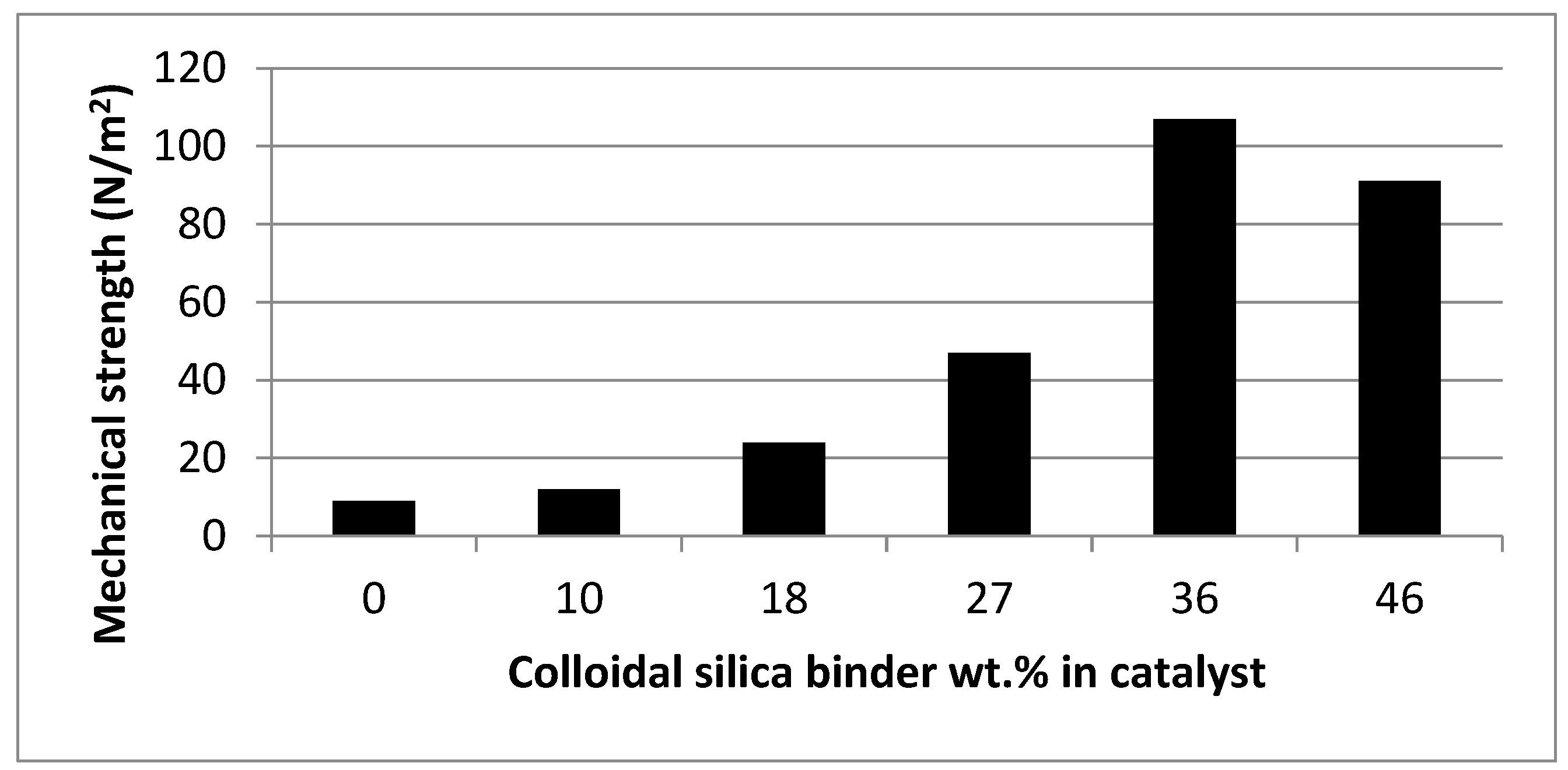
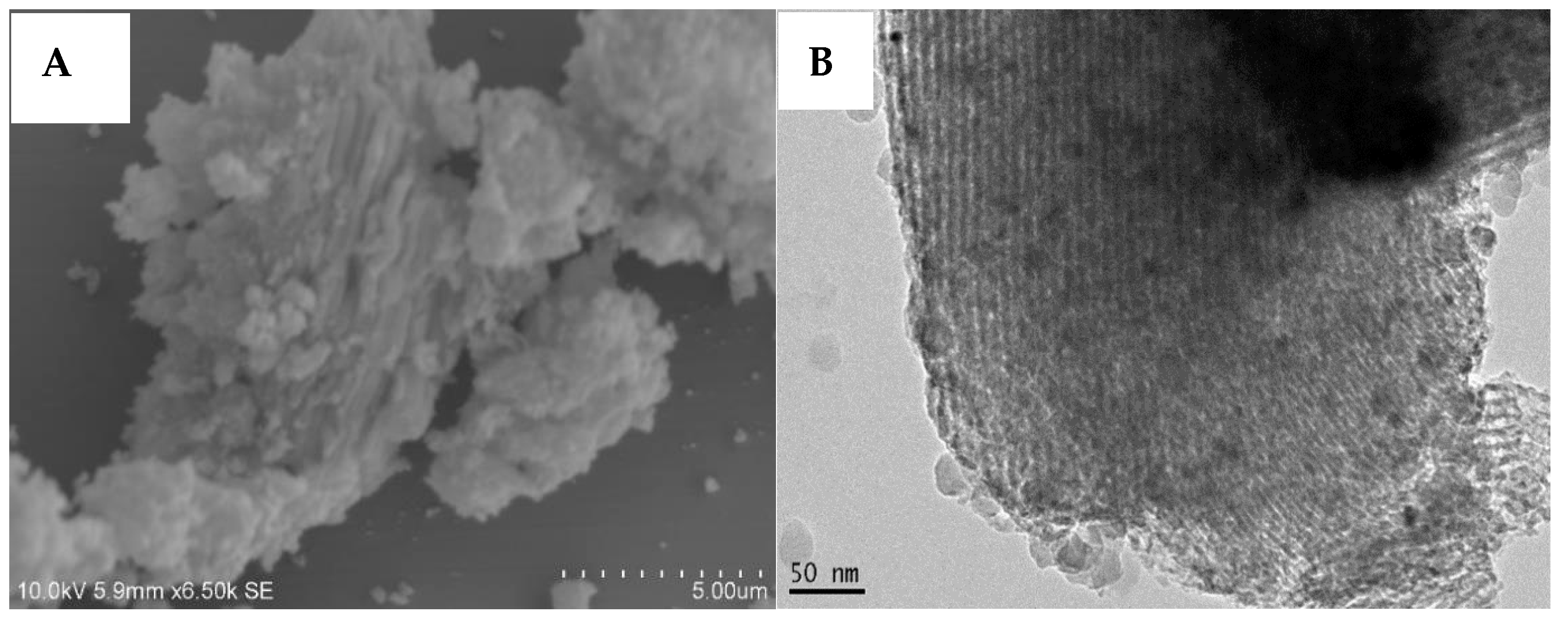
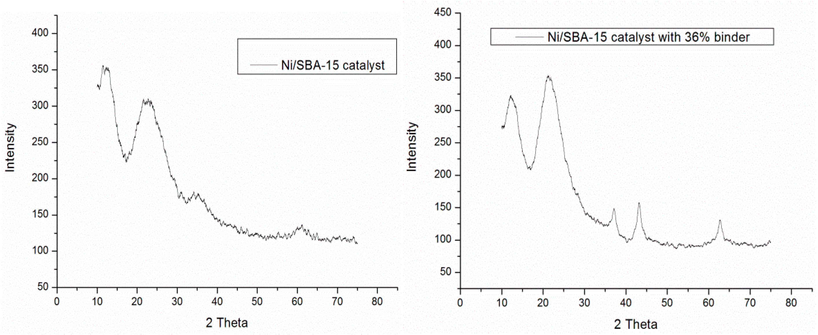
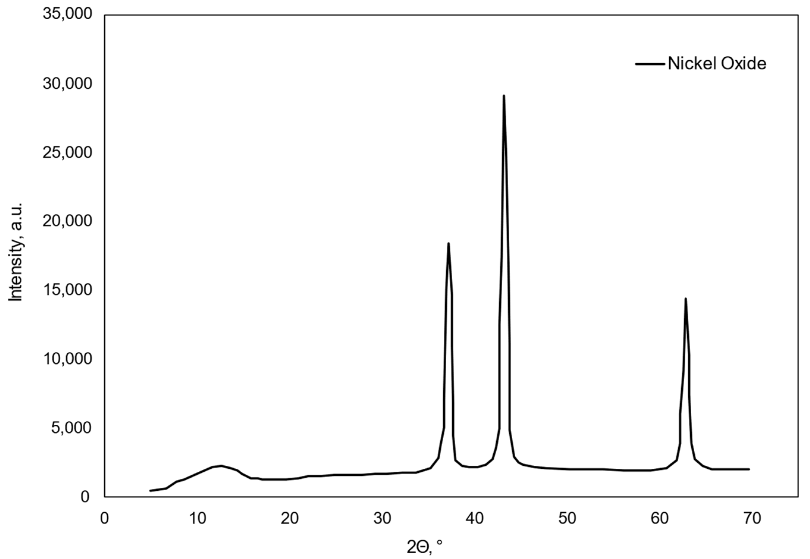
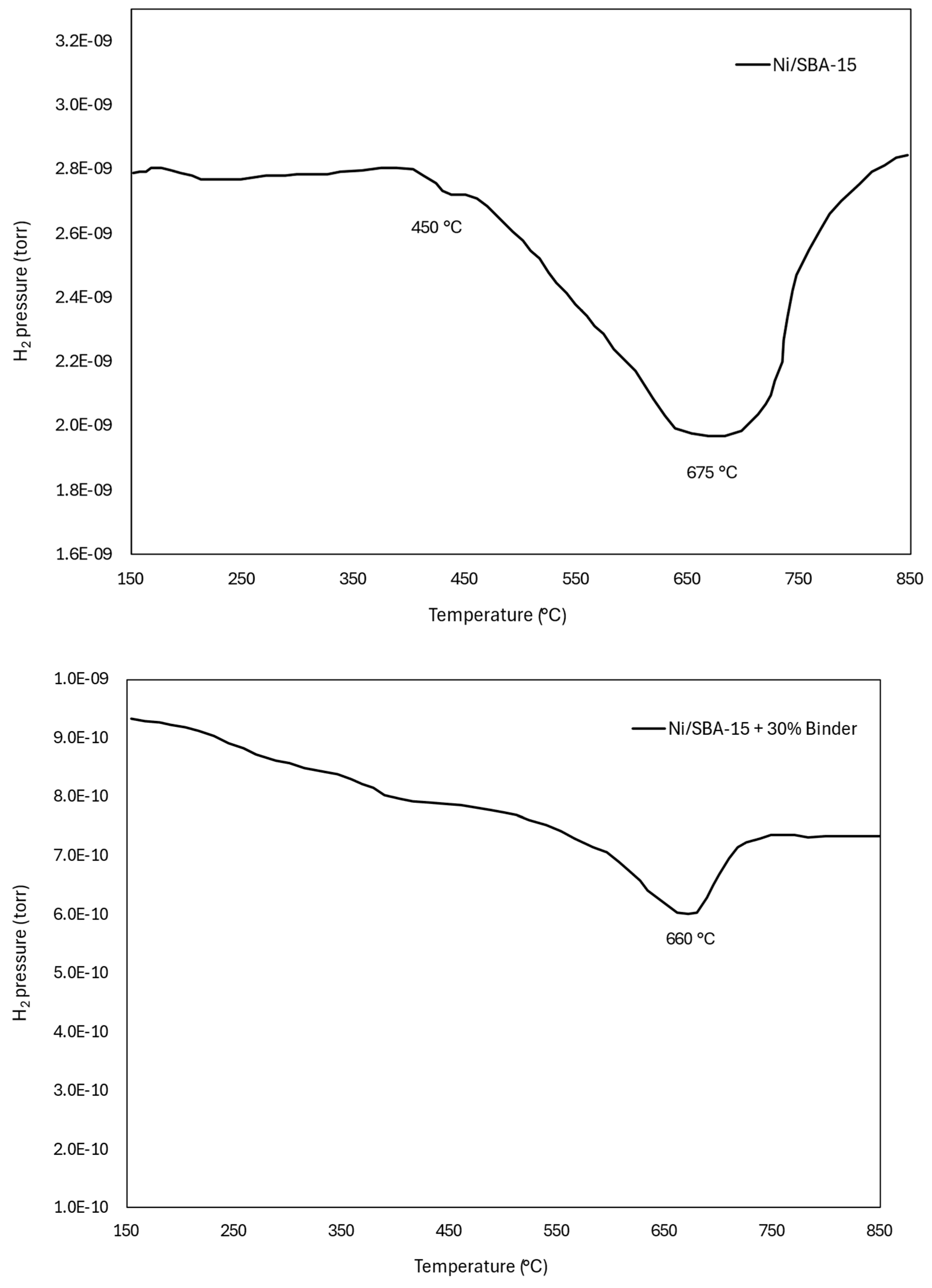
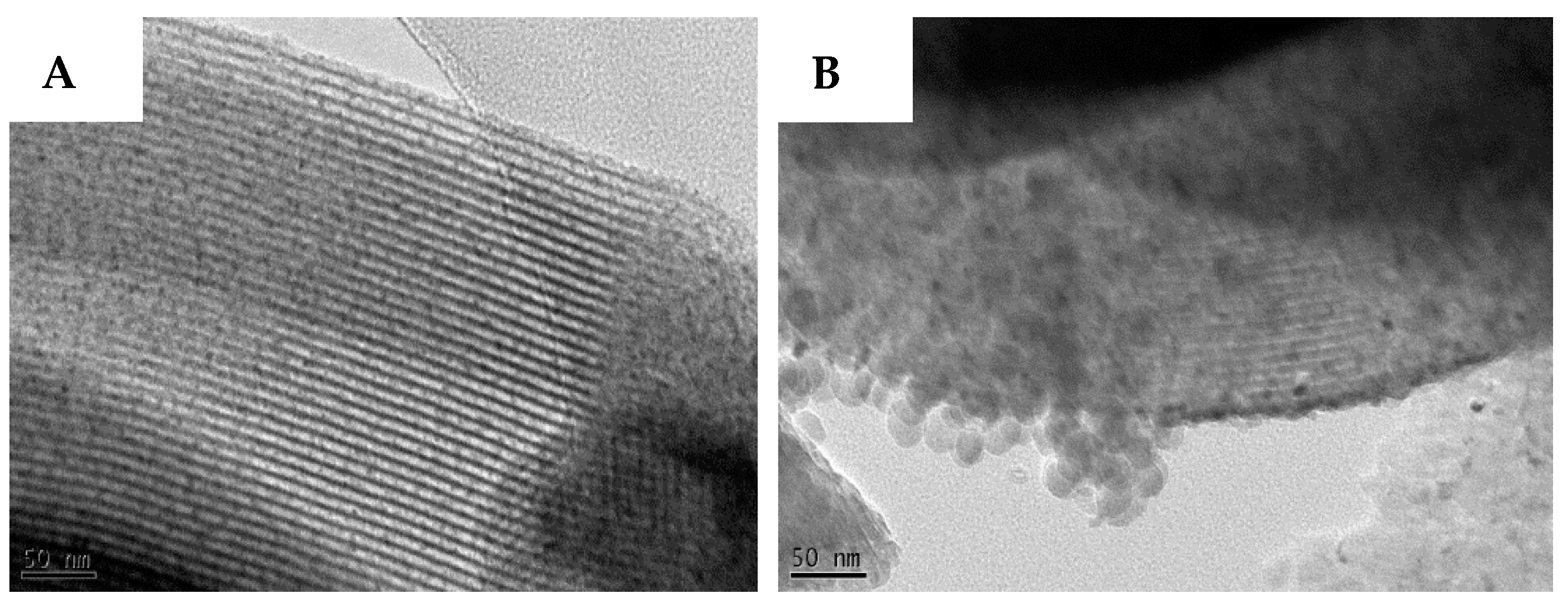
2.1. Catalyst Characterisation

The data compiled in Table 1 shows that the Ni/SBA-15 catalyst has a high surface area, large pore size and volume, and ultrafine nickel particles of 1–2 nm. Also, the data indicate that the addition of the binder led to a decrease in Ni loading and an increase in Ni particle size. These differences are attributed to the fact that the pellets underwent another calcination at a higher temperature than the powder, which, on one hand, reduced the specific surface area and on the other hand facilitated the grain growth via sintering.
Figure 1 shows the results of the single pellet mechanical strength test, indicating an optimum amount of the colloidal silica binder to be added to the catalyst for pellet manufacturing, at 36 wt.%. Therefore, catalyst pellets of Ni/SBA-15 with 36% binder were manufactured and were then characterised alongside the original powdered Ni/SBA-15 catalyst and the results were compared to study the effect of the binder on the physical and chemical properties of the catalyst.
SEM images of the fresh Ni/SBA-15 catalyst and fresh Ni/SBA-15 catalyst with 36% colloidal silica binder shown in Figure 2 confirm that the long fibre-like morphology of the Ni/SBA-15 catalyst was not destroyed but surrounded by the colloidal silica binder. Fiber-like or worm-like morphology is a characteristic of the SBA-15 support used to prepare the samples.
The size of the nickel particles and their dispersion on SBA-15 was assessed by TEM measurements and data analysis. The diameter of the nickel nanoparticles was analysed using the image analysis software, ImageJ, Ver. 1.53v (NIH).
TEM images taken on the fresh Ni/SBA-15 catalyst and fresh Ni/SBA-15 catalyst with 36% binder are shown in Figure 3. They reveal that the mesoporous structure of the support, i.e., SBA-15, was not affected by the addition of the binder, nor by the extra calcination step of the catalyst with the binder. Both images show similar arrays of narrow cylindrical pores with silica pore walls in between.
TEM images of the fresh Ni/SBA-15 catalyst show well-dispersed, hardly visible ultrafine nickel particles on the SBA-15 support. TEM images of the Ni/SBA-15 catalyst with 36% binder show that colloidal silica particles are much bigger than the catalyst pore diameter and are therefore only present on the external surface of the catalyst and not in the pores and so, pore blockage by the binder was avoided. The size of the nickel particles was determined to be 1–2 nm for the powdered sample and 7 nm for the pellet sample, respectively.
SEM and TEM measurements were taken on the used catalyst pellets as well and are shown in Figure 4. SEM images of the fresh (Figure 2B) and of the used catalyst pellets (Figure 4A) appear the same, which confirms that the reaction conditions did not destroy the morphology of the catalyst. The comparison of the TEM images of the fresh (Figure 3B) and used catalyst pellets (Figure 4B) reveals that the nickel particles were highly dispersed on the SBA-15 catalyst support of both fresh and used Ni/SBA-15 pellets. No major nickel aggregation was observed before or after the reaction, an indication that no significant nickel sintering and agglomeration occurred during the course of the reaction.
Figure 5 shows the XRD patterns of the Ni/SBA-15 catalyst and Ni/SBA-15 catalyst with 36wt.% binder, respectively. Also, XRD patterns were recorded for the nickel oxide sample, obtained from the calcined nickel acetate tetra hydrate salt at 550 °C, and are shown in Figure 6.
The wide-angle XRD peaks could be indexed to a face-centred cubic crystalline NiO structure indicating that NiO particles were also dispersed on the outer surface as well as on the pore surface of SBA-15. This finding is supported by TEM measurements as well. The characteristic reflection peaks of the crystalline nickel oxide appear at 36°, 44°, and 64° of 2θ, respectively. While all these characteristic reflection peaks appear in the XRD of the Ni/SBA-15 catalyst with 36% binder, only the peaks at 36° and 64° of 2θ appear in the XRD of the Ni/SBA-15 catalyst. They are broader than those appearing in the sample with the binder, which, in our opinion, shows that the NiO particles in the sample without the binder are smaller than those in the sample with the binder. The broader the peak, the smaller the particles. The formation of slightly bigger NiO particles on the pellets may be because of an extra calcination step in the preparation of the catalyst pellets, at higher temperature (750 °C), which caused some nickel oxide particles to sinter on the external surface of the catalyst. As all wide-angle peak intensities of NiO/SBA-15 with binder were greater than those without binder, the NiO amount located on the outer surface of NiO/SBA-15 with binder was high. In addition, a broad peak at 2θ = 17–29° caused by the amorphous SiO2 (JCPDS-card 96-900-1582) structure of SBA-15 was clearly observed in the wide-angle pattern, indicating that the ordered mesoporous SBA-15 structure (seen in TEM as well) was not disturbed by the included NiO.
The H2-TPR profiles of the powdered and pellet catalyst samples are shown in Figure 7. The TPR measurements were performed to assess the catalysts reducibility as a measure of the metal(catalyst)–support interaction. The TPR of the two catalysts are quite similar, with rather high reduction temperatures, i.e., 675 °C for Ni/SBA-15 catalyst and 660 °C for Ni/SBA-15 with a 36% binder catalyst, respectively. The high reduction temperatures indicate a strong catalyst–support interaction for both samples, albeit slightly stronger for the Ni/SBA-15 catalyst, as its reduction temperature is slightly higher. The strong catalyst–support interaction explains the high dispersion of the nickel species on the support and their small and relatively small sizes. What is more, strong catalyst–support interactions led to the encapsulation and stabilisation of metal nanoparticles with the support that significantly impacts catalytic performance through regulation of the interfacial interactions. High catalytic activity measured for both samples supports the beneficial role of the catalyst–support interactions. However, the intensity of the reduction of the Ni/SBA-15 catalyst is higher, consuming 29% of hydrogen compared with Ni/SBA-15 with 36% binder which consumed 16% of hydrogen during reduction. The reason for the difference in the amount of hydrogen consumed may be due to the lower amount of nickel content in Ni/SBA-15 with 36% binder catalyst (4 wt.%) compared to the original Ni/SBA-15 catalyst (5.7 wt.%).
The presence of a second reduction peak at 450 °C, slightly less pronounced for the catalyst sample with binder, suggests a two-step reduction mechanism. The first peak could be ascribed to the reduction of surface amorphous nickel oxides possessing a weak interaction with the support and the second one could be due to the reduction of crystal NiO species with a stronger interaction with the support.

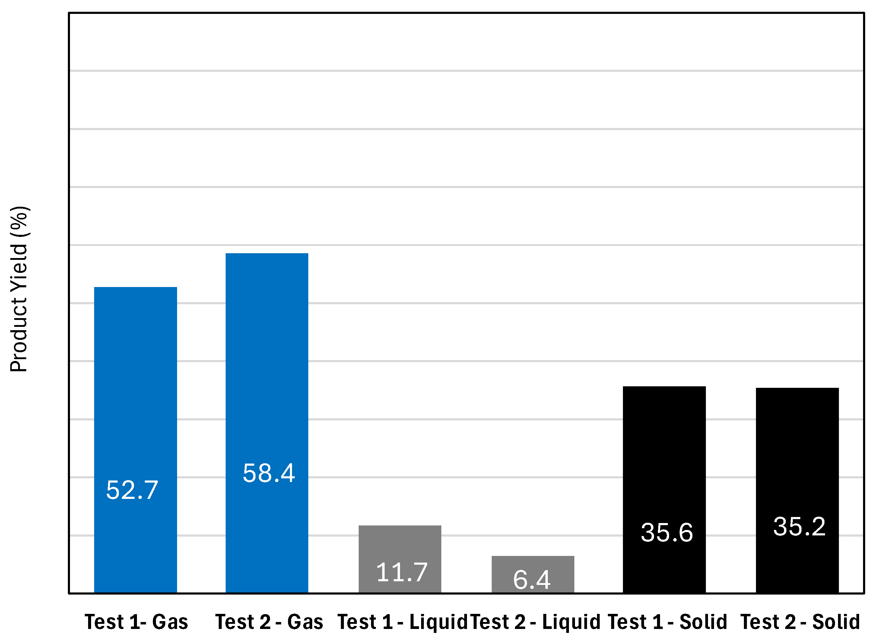
2.2. Pilot Plant Results and Discussion

The pyrolysis of dried sewage sludge was carried out without and with the catalytic reactor containing 1 kg of Ni/SBA-15 catalyst pellets. The cooled liquid and solid fraction yields were collected and weighed, while the gas fraction was calculated by mass balance. The pyrolysis test without a catalytic reactor is labelled Test 1, while the test run with the catalytic reactor is labelled Test 2. The product yield distribution shown in Figure 8 reveals that the chosen pyrolysis operating conditions favoured more gas production, however, the formation of the liquid and solid fractions are inevitable. The introduction of the catalytic unit had a significant effect on the product yield as the gas fraction increased from 52.7 to 58.4%. The increase in the gas fraction is due to tar catalytic cracking to non-condensable gas, causing the liquid fraction to drop from 11.7 to 6.4%. The use of a catalyst did not change the solid fraction yield since only the volatile products were passed through the catalytic reactor. The solid fractions for Tests 1 and 2 were collected separately before catalytic cracking.

2.2.1. Characterisation of Pyrolysis Liquid Fraction Without Catalytic Cracking

The liquid fraction from the pyrolysis of sewage sludge without the catalytic reactor was analysed to determine its composition. Analysis data are presented in Table 2 and show that not all of the liquid fraction is tar. Instead, 55% of the liquid is water which may have come from both condensation reactions during pyrolysis and some moisture in the sludge which had a 7.8% moisture content. It therefore means that the remaining 45% measured by mass balance is considered tar. Pyrolysis liquid contains 4803 µg/mL and 704 µg/mL nitrogen and sulphur, respectively. Sulphur is known to deactivate most of the reported catalysts, and so, only sulphur-tolerant catalysts, such as the novel Ni/SBA-15 catalyst, can remain catalytically active in tar cracking with this high sulphur content.
The pyrolysis liquid fraction (tar) was analysed in GC-MS and the composition of the organic compounds was quantified as shown in Table 3. Tar from the pyrolysis of sewage sludge contains a mixture of different organic compounds. Polycyclic aromatic hydrocarbons (PAHs) were not detected which suggests that pyrolysis at 800 °C was sufficient to decompose PAHs in the liquid fraction, leaving only lighter aromatics, aliphatic, phenols, etc. In addition to light aromatics excluding benzene, the tar sample has a high pyridine content (20.2%) and lower acids content (9.1%), which explains why the pyrolysis liquid fraction is basic with a pH of 9 and why 55% of the liquid fraction is water which mostly resulted from the many condensation reactions that occurred during pyrolysis.

2.2.2. Pyrolysis Gas Composition

The composition of the non-condensable gas fractions before and after the introduction of the catalytic reactor is shown in Figure 9.
The use of the Ni/SBA-15 pellet catalyst had a significant effect on the gas composition as H2 increased from 22.24% to 28.11%, CO increased from 25.99% to 30.59%, and CO2 decreased from 12.25% to 10.27% due to the fact that some dry (CO2) reforming of methane took place alongside catalytic tar cracking with the Ni/SBA-15 catalyst. Some of the non-condensable hydrocarbons were cracked to smaller fractions as they decreased slightly from 2.88% to 2.76%. The calorific value of the pyrolysis gas increased from 16.56 MJ/m3 without a catalytic reactor to 18.74 MJ/m3 with the catalytic reactor due to the increase in H2, CO, CH4, and CnHm and a decrease in CO2 content arising from catalytic tar cracking.
Since the amount of pyrolysis liquid decreased from 11.7% to 6.4%, which corresponds to a 45% decrease in the liquid fraction (Figure 8), and the pyrolysis liquid constitutes 55% water and 45% tar (Table 2), it is therefore plausible to say that 100% of the tar present in the liquid fraction was converted to non-condensable gases by catalytic cracking with the novel Ni/SBA-15 catalyst pellets.

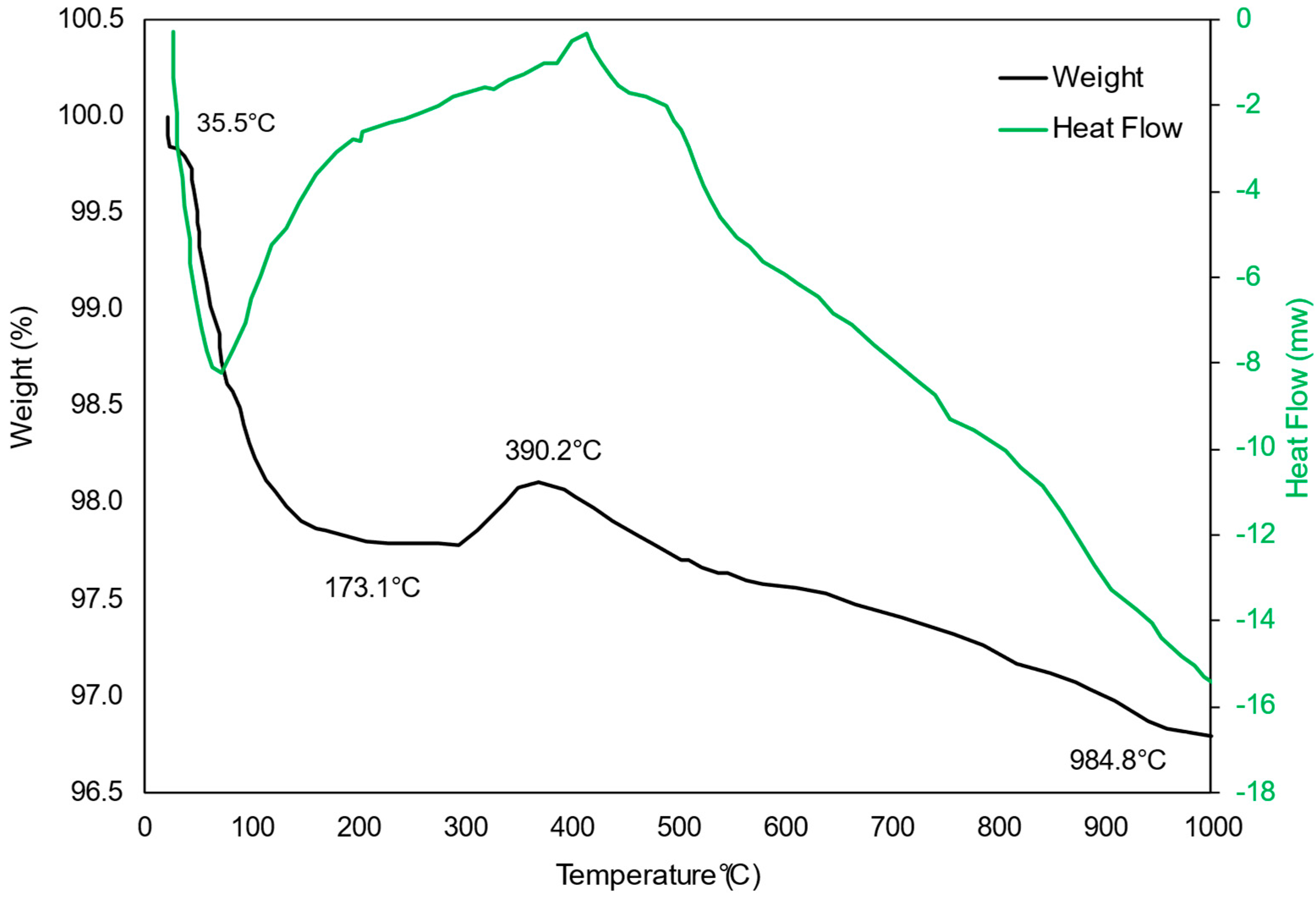
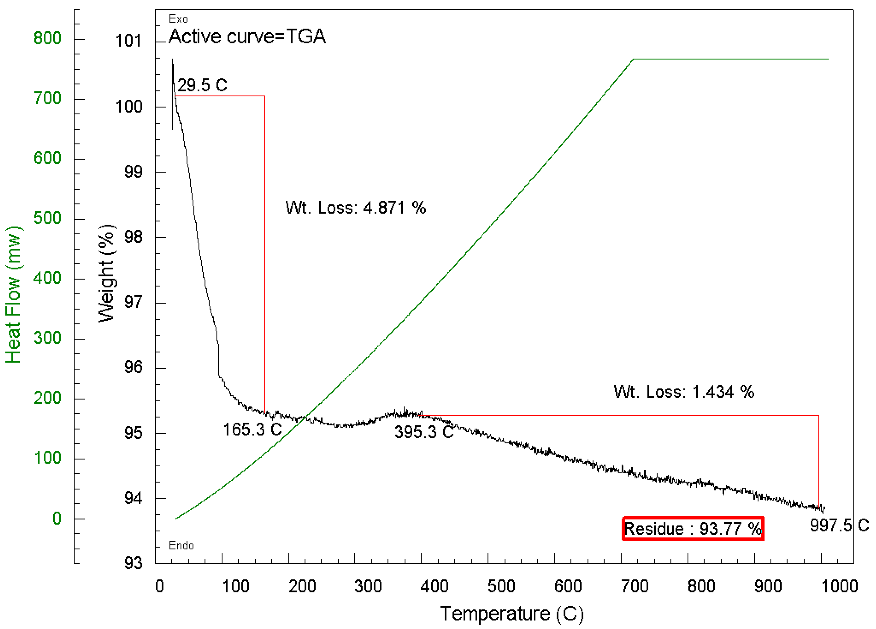
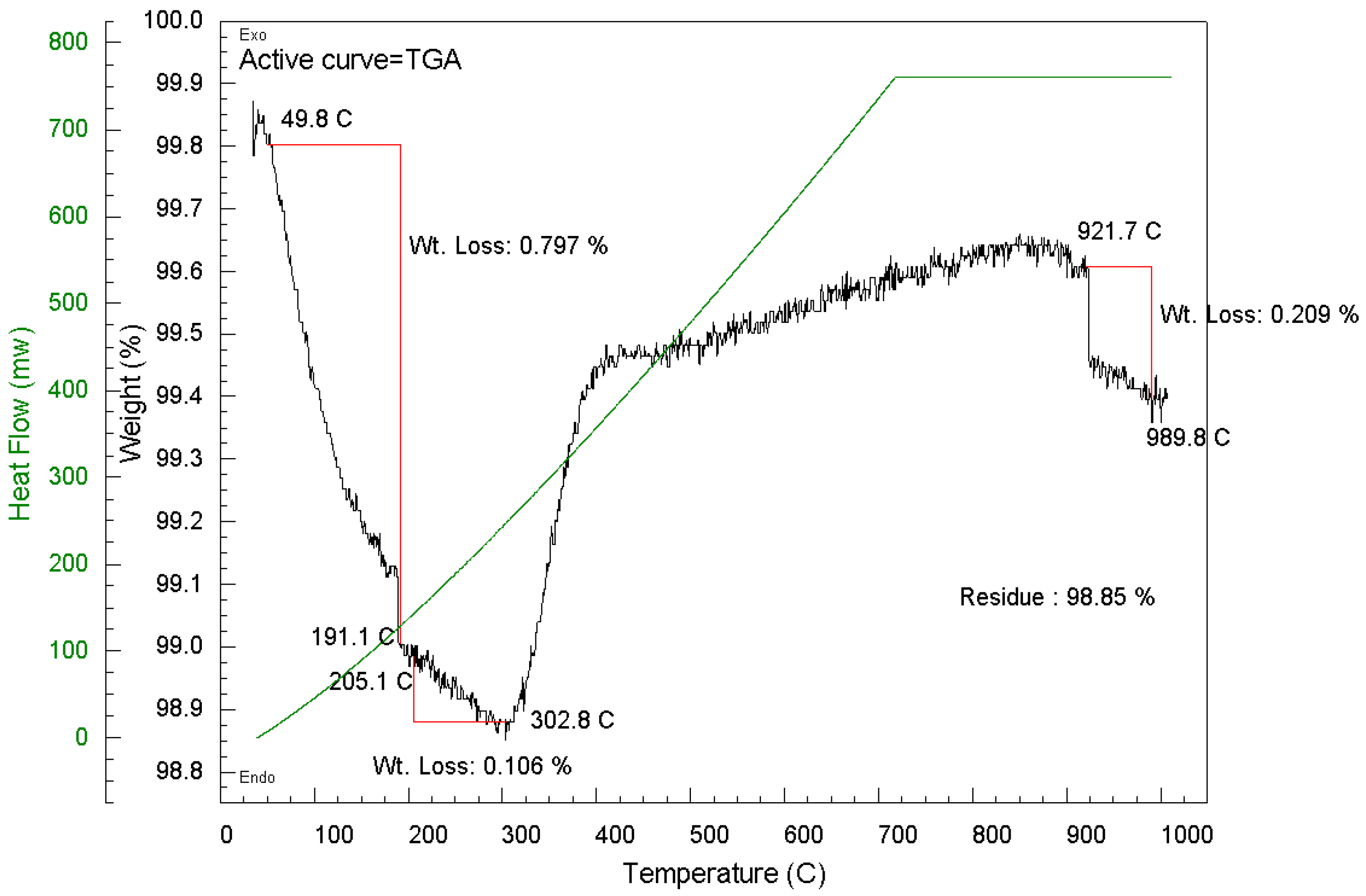
2.2.3. Thermogravimetric Analysis (TGA) of Spent Pellet Catalyst

The major hindrance to the commercialisation of nickel-based catalysts for tar cracking is that they are easily prone to carbon deposition which results in catalyst deactivation over a short period of time. The TGA of the spent catalyst (Figure 10) from Test 2 revealed that only a small amount of carbon deposition (1.27%) was present on the spent catalyst. DSC temperature for the oxidation of the carbon species occurred at 390 °C, an indication that the carbon type is amorphous which is easily oxidised during the reaction [45]. Since the catalyst remained highly active throughout the duration of the experiment, one can conclude that the small carbon deposition did not inhibit catalytic performance, as the ultrafine nickel particles were active enough to prevent any major carbon build-up.

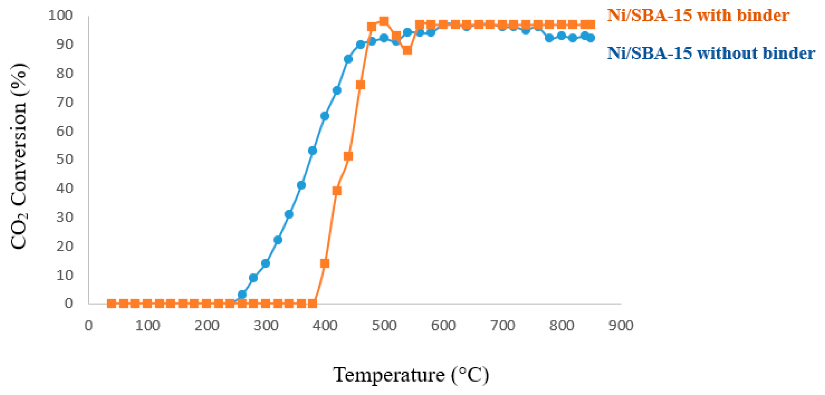
2.3. Catalytic Activity Evaluation

Catalytic activity tests were carried out with a Hiden Analytical CATLAB—quadrupole mass spectrometer micro-reactor system (fixed-bed quartz tube 4 mm i.d and 18.5 cm in length) in continuous flow. Hydrogen temperature programmed reduction was conducted by flowing 5% H2 in Ar at a flow rate of 30 mL/min, with the reactor heated from room temperature to 850 °C at a 20°/min ramp rate. The catalytic activity measurements of hydrogen-reduced catalysts were carried out at a GHSV of 888 h−1 for a CH4/CO2 reactant ratio of 2.7. The amount of carbon deposition on the spent catalysts after the reaction was measured by the thermal gravimetric analysis (TGA) of Thorn Scientific Services in an oxidative atmosphere with a heating temperature raised from room temperature to 1000 °C at a 10°/min ramp rate.

2.3.1. Catalytic Activity Evaluation via Temperature-Programmed Reaction (TPRx)

A CH4/CO2 reactant ratio of 2.7 was used to test and compare the catalytic activity of the Ni/SBA-15 sample without binder and of that with 36% colloidal silica binder. The difference in catalytic performance is seen in Figure 11. For the Ni/SBA-15 catalyst with binder, the initial reaction temperature starts at 380 °C, unlike the Ni/SBA-15 catalyst without binder, which starts at 280 °C. It is possible that this catalyst was more active at lower temperature due to the presence of smaller sized nickel particles which proved to be more active than the 7 nm-sized nickel particles for the Ni/SBA-15 catalyst with binder at a lower reaction temperature. At higher reaction temperatures of 560–850 °C, the Ni/SBA-15 catalyst with binder attained 97% CO2 conversion and remained stable up to an 850 °C optimum test temperature. The Ni/SBA-15 catalyst without binder also had high CO2 conversion which, however, fluctuated between 92 and 97%. The reason for the higher catalytic stability of the Ni/SBA-15 catalyst with 36% colloidal silica binder may be that the binder acted as a shield which restricted the mobility, agglomeration, and sintering of nickel particles outside the pores of the catalyst, thereby improving significantly the catalyst activity and stability in high reaction temperatures.

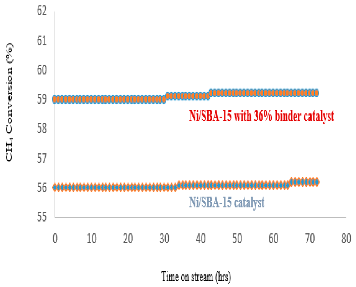
2.3.2. Catalyst Life-Time Test on Stream

Figure 12 and Figure 13 present the variation of CO2 and CH4 conversion during the time-on-stream measurements. The two catalysts proved to be highly active and stable throughout the 72 h’s test period producing H2 and CO only.
The Ni/SBA-15 catalyst maintained 87–88% CO2 conversion, while the Ni/SBA-15 catalyst with binder had a higher CO2 conversion of 97%. With methane conversion, the Ni/SBA-15 catalyst with 36% colloidal silica binder was stable at 59%, while the Ni/SBA-15 catalyst was stable at 56%. This indicates that the addition of colloidal silica binder did not inhibit the catalytic activity of the Ni/SBA-15 catalyst; rather, it seems to have resisted the mobility of some of the nickel particles on the external surface, that is, outside of the catalyst pores, thereby reducing the agglomeration and sintering of some nickel particles which consequently increased the catalytic activity of Ni/SBA-15 catalyst with 36% colloidal silica binder at a high reaction temperature range.
The two catalysts proved to be highly active and stable throughout the 72 h’s test period producing H2 and CO only. TEM images of the spent catalysts shown in Figure 14 reveal no major agglomeration of nickel particles after the reaction, and the pore channels of the catalysts were not destroyed, a further confirmation that the catalysts are highly stable in high-temperature DRM reactions.
The catalysts’ resistance to coke formation was assessed via TGA measurements again after the 72 h’s time-on-stream. The weight loss recorded in the TGA results for both catalysts, which corresponds to the amount of carbon lost via oxidation in air, is shown in Figure 15 and Figure 16. Weight loss within 160 °C is attributed to the loss of adsorbed moisture on the catalysts. Both catalysts recorded only a small amount of carbon deposition. However, the Ni/SBA-15 catalyst with 36% binder had the lowest level of carbon deposition at 0.32%, while the Ni/SBA-15 catalyst had a level of 1.43% after 72 h’s time-on-stream at 700 °C. This further explains why the Ni/SBA-15 catalyst with binder was slightly more active; less nickel sintering occurred on the catalyst with binder during the time-on-stream test, and so, it had a better level of resistance against carbon deposition. This finding confirms that colloidal silica binder acted as a shield which restricted the mobility, agglomeration, and sintering of nickel particles outside the pores of the catalyst, thereby improving significantly the catalyst activity and stability in high reaction temperatures.
However, the amount of carbon formed on both catalysts was relatively small and did not in any way decrease the activity or stability of the catalysts during the 72-h time-on-stream.

3. Experimental Procedure

3.1. Preparation of Ni/SBA-15 Powder Catalysts

A series of Ni/SBA-15 catalysts were synthesised using novel preparation methods with [Ni(En)3]2+ (En = ethylenediamine), [Ni(NH3)6]2+ and [Ni(EDTA)]2− complexes, respectively, loaded on a highly stable SBA-15 mesoporous silica support by the strong electrostatic adsorption impregnation method and compared with the conventional incipient wetness impregnation method with [Ni(H2O)6]2+ complex. They were then characterised to investigate the possibility of generating smaller nickel particles that are highly and uniformly dispersed on the support with stronger metal–support interactions for high activity catalysts resistant to the usual problematic carbon deposition, sintering, and deactivation phenomena associated with nickel-based catalysts in the dry reforming of methane. The samples prepared with the [Ni(NH3)6]2+ complex produced ultrafine nickel oxide particles not visible in TEM with the strongest metal–support interaction, highest activity, and resistance to coking. Therefore, this sample was only later shaped into pellets and scaled up, as presented in our paper.
The preparation method of this sample is detailed below.
About 1.5 g of prepared SBA-15 [46] was placed in a beaker with 20 mL deionised water and stirred for 30 min at room temperature before cooling to 5 °C, while stirring. A few drops of NH4OH were added to the SBA-15 solution to raise the pH to 12.
In another beaker, [Ni(NH3)6]2+ complex was synthesised by placing 1 g of nickel acetate tetra hydrate (9.998%, Sigma Aldrich, St. Louis, MO, USA) in 10 mL deionised water and stirred for 30 min at room temperature which resulted in a green clear solution without precipitates. Afterwards, the solution was cooled to 5 °C, and while stirring, ammonium hydroxide previously cooled to 0 °C was added dropwise until the solution changed from green to deep blue (~2.5 mL NH4OH added). The synthesised [Ni(NH3)6]2+ complex was then poured into SBA-15 solution and stirred for another 30 min. The sample was then filtered, washed several times with deionised water, and air dried for 3 days in a fume cupboard before calcination at 550 °C for 6 h at a 1°/min ramp rate.

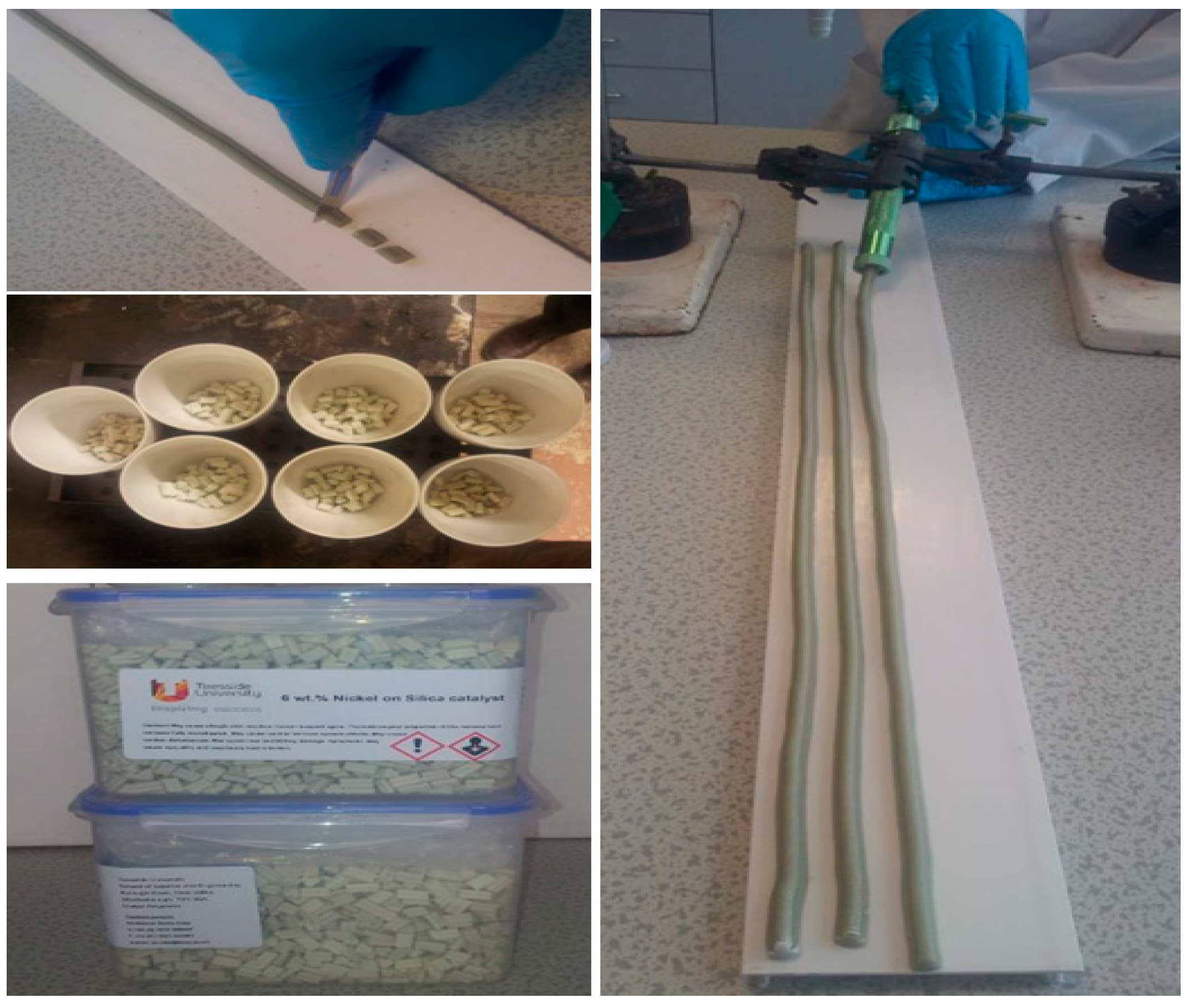
3.2. Preparation of Ni/SBA-15 Catalyst Pellets

The powder of the catalyst sample as prepared above was shaped using binders which also offer higher mechanical strength to the pellets. The selection of an appropriate binder is of utmost importance since binders can negatively affect the activity of catalysts. Also, formulating the right catalyst/binder ratio which offers higher mechanical strength without adversely affecting the activity of the catalyst can be quite challenging even for renowned catalyst manufacturers. Two inorganic binders, sepiolite (13% magnesium, <2% impurities such as aluminium and iron and the rest been silica) and colloidal silica (pure 50% silica in water) with an appropriate amount of organic binder, methyl cellulose, and water, were used for catalyst pellet formulation. Inorganic binders were added in order to increase the mechanical strength of extrudates, whereas organic binder was used as plasticiser to enhance the viscosity of the paste during the extrusion. The percentages of added sepiolite and colloidal silica were 10, 18, 27, 36, 46, and 58%, while the amount of methyl cellulose was kept at a fixed amount of 5 g.
The colloidal silica binder produced pellets with higher mechanical strength. Therefore, colloidal silica was the chosen binder to shape and scale up the catalyst sample prepared with the [Ni(NH3)6]2+ complex.
The detailed preparation method of the catalyst pellets is presented below.
To obtain catalyst pellets with high mechanical strength, 5 g of methyl cellulose was first added to six different mass samples of powdered Ni/SBA-15 catalyst and mixed for 1 h using a magnetic stirrer. Different amounts of deionised water and LUDOX® TM—50 Colloidal Silica (50 wt.% suspension in water, Grace & Co., Columbia, MD, USA) was then added to the powdered Ni/SBA-15 catalyst/methyl cellulose and mixed manually to form a paste. The paste was extruded using a small manually operated extruder and cut into pellets with a sharp knife. The pellets were air dried for 24 h and calcined at 750 °C for 6 h at a 1°/min ramp rate to burn off the methyl cellulose. A summary of the mixtures and pictures of the extrusion process are shown in Table 4 and Figure 17.

3.3. Characterisation of Prepared Catalyst Pellets

The mechanical strength and resistance to crushing of the Ni/SBA-15 catalyst extrudates with various amounts of colloidal silica binder (0–46%) was tested using an Instron® Model 3367 Electromechanical test machine. Statistically, a mean average result of ten pellets vertically and horizontally crushed were used to select the extrudate with the highest mechanical strength. The pellet mixture with the highest mechanical strength was crushed into powder form, characterised further, and compared with the original Ni/SBA-15 catalyst without binder. The BET method was used to calculate the surface area, pore size, and volume of the catalysts using nitrogen adsorption—desorption data were obtained in Micrometrics Tristar II degassed at 350 °C for 2 h. The Scanning Electron Microscope (SEM) Hitachi S-3400N was used to study the morphology of the catalysts. Energy-Dispersive X-ray spectroscopy (EDX) was carried out to compare the amount of nickel loading on the catalysts. Wide-angle X-ray Diffraction spectroscopy (XRD) patterns collected over a 2θ range from 10° to 75° using a Siemens D500 diffractometer with CuK αradiation (1.54 Å) were used to detect and calculate the nickel average particle size on catalysts. Transmission Electron Microscopy (TEM) was carried out on a JEOL 2100F FEG operating at 200 kV with samples ultra-sonicated and dispersed onto holey carbon grids for examination in TEM mode to study the dispersion of nickel on SBA-15.

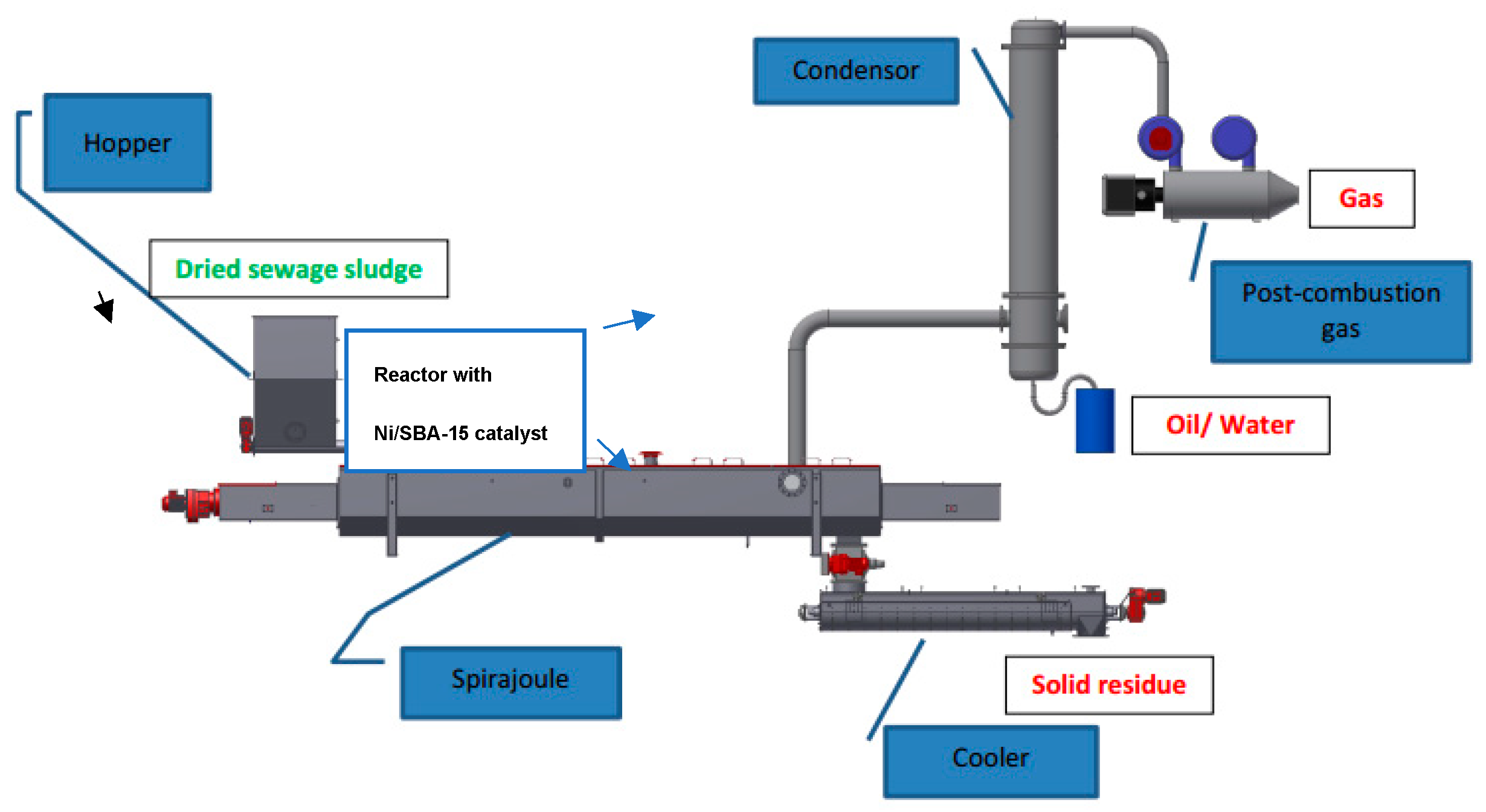
3.4. Pilot Plant Test Procedure

The Biogreen® process patented by ETIA for thermochemical conversion was used for this research study. A catalytic reactor 12 cm in diameter and 30 cm in length containing 1 kg of the novel Ni/SBA-15 catalyst pellets with a bed porosity of approximately 0.4 was fitted to the pyrolysis reactor, so that the exiting raw hot vapour stream first passes through the catalytic reactor before analysis as illustrated in Figure 18.
The continuous pyrolysis of dried sewage sludge was carried out at a constant residence time of 20 min regulated by screw rotation speed settings for each set of the experiments. The pyrolysis reactor temperature was maintained at 800 °C by its low-voltage electrically heated screw conveyor, because of the Joule effect. The solid residue from pyrolysis was cooled in a double jacket cooler and collected in a separate container as shown in Figure 8. The raw vapour, either with or without the catalytic reactor, was passed through a condenser and any condensed liquid fraction was collected in a separate container. A summary of the operating conditions used for the pyrolysis of dried sewage sludge is shown in Table 5:

3.5. Analysis of Liquid and Gas Pyrolysis Fractions

The water content in the pyrolysis liquid fraction was determined using fractional distillation. Nitrogen and sulphur content in the liquid fraction was analysed with an Antek 9000 Nitrogen/Sulphur Analyser. Organic compounds in tar were analysed offline with gas chromatography mass spectrometry (GC-MS). Non-condensable gases were analysed online with a gas chromatographand the rest of the gas burnt safely in a combustion chamber.

4. Conclusions

The purpose of this contribution was to develop, scale up, and test in a dried sewage sludge pyrolysis pilot plant novel Ni/SBA-15 catalysts. The Ni/SBA-15 catalysts were prepared by a strong electrostatic adsorption impregnation method and shaped into pellets by extrusion, using methyl cellulose and colloidal silica as binders. Pilot plant tests revealed that the catalyst pellets were able to crack 100% of tar into hydrogen, carbon monoxide, and methane. The dry reforming of methane in the hot gas also took place. A combination of catalytic DRM and tar cracking significantly increased the gas fraction, reduced CO2 content, and increased the final gas calorific value. Characterisation results showed that the Ni/SBA-15 catalyst pellets remained active and did not sinter nor deactivate from carbon deposition. The small size of Ni particles (about 7 nm) and their high dispersion on the support, a strong metal–support interaction, and the binder acting as a shield explain the catalyst’s high activity, stability, and resistance to coke formation. The ability to shape Ni-SBA-15 catalysts into pellets is a major step towards the large-scale commercialisation of the catalytic tar cracking of hot vapour derived from biomass pyrolysis into syngas for various applications.

Author Contributions

Conceptualisation, M.O.; methodology, E.I. and S.H.; validation, M.O.; investigation, E.I., S.H. and T.S.; writing—original draft, E.I.; writing—review and editing, M.O.; graphical abstract: S.H.; supervision, M.O. All authors have read and agreed to the published version of the manuscript.

Funding

This research has received funding from the European Union’s Seventh Framework Programme managed by REA-Research Executive Agency (FP7/2007-2013) under Grant agreement N° 603394. As for the APC, 10% was covered by a IOAP discount, while for the remaining 90%, an author voucher discount code (0b4c41c7b1c4e896) was provided by MDPI.

Data Availability Statement

The raw data supporting the conclusions of this article will be made available by the authors on request.

Acknowledgments

T.S. kindly acknowledges The Institute for Solid State Physics, The University of Tokyo, for access to TEM.

Conflicts of Interest

Author Emmanuel Iro was employed by the company UNICAT Catalysts Technologies, LLC. The remaining authors declare that the research was conducted in the absence of any commercial or financial relationships that could be construed as a potential conflict of interest.

References

  1. Commission of European Communities. Council Directive 91/271/EEC of 21 March 1991 Concerning Urban Waste-Water Treatment (Amended by the 98/15 EC of 27 February 1998), Official Journal of the European Communities, 30.5.91, No L 135/40. Available online: https://www.legislation.gov.uk/eudr/1998/15/contents (accessed on 28 January 2025).
  2. Williams, G.; Aitkenhead, N. Lessons from Loscoe: The uncontrolled migration of landfill gas. Q. J. Eng. Geol. Hydrogeol. 1991, 24, 191–207. [Google Scholar] [CrossRef]
  3. Boeckx, P.; Cleemput, O.V.; Villaralvo, I. Methane emission from a landfill and the methane oxidising capacity of its covering soil. Soil Biol. Biochem. 1996, 28, 1397–1405. [Google Scholar] [CrossRef]
  4. Mosher, B.W.; Czepiel, P.M.; Harriss, R.C.; Shorter, J.H.; Kolb, C.E.; McManus, J.B.; Allwine, E.; Lamb, B.K. Methane Emissions at Nine Landfill Sites in the Northeastern United States. Environ. Sci. Technol. 1999, 33, 2088–2094. [Google Scholar] [CrossRef]
  5. Al-Dabbas, M.D.A.F. Reduction of methane emissions and utilization of municipal waste for energy in Amman. Renew. Energy 1998, 14, 427–434. [Google Scholar] [CrossRef]
  6. Zamorano, M.; Pérez, J.I.P.; Pavés, I.A.; Ridao, Á.R. Study of the energy potential of the biogas produced by an urban waste landfill in Southern Spain. Renew. Sustain. Energy Rev. 2007, 11, 909–922. [Google Scholar] [CrossRef]
  7. Lundin, M.; Olofsson, M.; Pettersson, G.J.; Zetterlund, H. Environmental and economic assessment of sewage sludge handling options. Resour. Conserv. Recycl. 2004, 41, 255–278. [Google Scholar] [CrossRef]
  8. Harakeh, S.E.; Mahmood, N.; Zhang, Y. Sewage Sludge Process Improvement Investigation for London, Ontario in: Green Fuels and Chemicals; University of Western Ontario, Department of Chemical and Biochemical Engineering: London, UK, 2011. [Google Scholar]
  9. Maschio, G.; Koufopanos, C.; Lucchesi, A. Pyrolysis, a promising route for biomass utilization. Bioresour. Technol. 1992, 42, 219–231. [Google Scholar] [CrossRef]
  10. Bridgwater, A.V. The technical and economic feasibility of biomass gasification for power generation. Fuel 1995, 74, 631–653. [Google Scholar] [CrossRef]
  11. Higman, C.; Van der Burgt, M. Gasification; Gulf Professional Publishing: Houston, TX, USA, 2011. [Google Scholar]
  12. McKendry, P. Energy production from biomass (part 3): Gasification technologies. Bioresour. Technol. 2002, 83, 55–63. [Google Scholar] [CrossRef] [PubMed]
  13. Hu, Z.-B.; Saman, W.R.G.; Navarro, R.R.; Wu, D.-Y.; Zhang, D.-L.; Matsumura, M.; Kong, H.-N. Removal of PCDD/Fs and PCBs from sediment by oxygen free pyrolysis. J. Environ. Sci. 2006, 18, 989–994. [Google Scholar] [CrossRef] [PubMed]
  14. Manara, P.; Zabaniotou, A. Towards sewage sludge based biofuels via thermochemical conversion—A review. Renew. Sustain. Energy Rev. 2012, 16, 2566–2582. [Google Scholar] [CrossRef]
  15. Fonts, I.; Azuara, M.; Gea, G.; Murillo, M.B. Study of the pyrolysis liquids obtained from different sewage sludge. J. Anal. Appl. Pyrolysis 2009, 85, 184–191. [Google Scholar] [CrossRef]
  16. Domínguez, A.; Fernández, Y.; Fidalgo, B.; Pis, J.J.; Menéndez, J.A. Bio-syngas production with low concentrations of CO2 and CH4 from microwave-induced pyrolysis of wet and dried sewage sludge. Chemosphere 2008, 70, 397–403. [Google Scholar] [CrossRef]
  17. Karayildirim, T.; Yanik, J.; Yuksel, M.; Bockhorn, H. Characterisation of products from pyrolysis of waste sludges. Fuel 2006, 85, 1498–1508. [Google Scholar] [CrossRef]
  18. Font, R.; Fullana, A.; Conesa, J.A.; Llavador, F. Analysis of the pyrolysis and combustion of different sewage sludges by TG. J. Anal. Appl. Pyrolysis 2001, 58–59, 927–941. [Google Scholar] [CrossRef]
  19. Sánchez, M.E.; Martínez, O.; Gómez, X.; Morán, A. Pyrolysis of mixtures of sewage sludge and manure: A comparison of the results obtained in the laboratory (semi-pilot) and in a pilot plant. Waste Manag. 2007, 27, 1328–1334. [Google Scholar] [CrossRef] [PubMed]
  20. Shafizadeh, F. Introduction to pyrolysis of biomass. J. Anal. Appl. Pyrolysis 1982, 3, 283–305. [Google Scholar] [CrossRef]
  21. Inguanzo, M.; Domı, A.; Menéndez, J.A.; Blanco, C.G.; Pis, J.J. On the pyrolysis of sewage sludge: The influence of pyrolysis conditions on solid, liquid and gas fractions. J. Anal. Appl. Pyrolysis 2002, 63, 209–222. [Google Scholar] [CrossRef]
  22. Bridgwater, A. Renewable fuels and chemicals by thermal processing of biomass. Chem. Eng. J. 2003, 91, 87–102. [Google Scholar] [CrossRef]
  23. Ábrego, J.; Arauzo, J.; Sánchez, J.L.; Gonzalo, A.; Cordero, T.; Rodríguez-Mirasol, J. Structural changes of sewage sludge char during fixed-bed pyrolysis. Ind. Eng. Chem. Res. 2009, 48, 3211–3221. [Google Scholar] [CrossRef]
  24. Park, H.J.; Heo, H.S.; Park, Y.-K.; Yim, J.-H.; Jeon, J.-K.; Park, J.; Ryu, C.; Kim, S.-S. Clean bio-oil production from fast pyrolysis of sewage sludge: Effects of reaction conditions and metal oxide catalysts. Bioresour. Technol. 2010, 101, S83–S85. [Google Scholar] [CrossRef] [PubMed]
  25. Piskorz, J.; Scott, D.S.; Westerberg, I.B. Flash pyrolysis of sewage sludge. Ind. Eng. Chem. Process Des. Dev. 1986, 25, 265–270. [Google Scholar] [CrossRef]
  26. Mercader, F.D.M.; Groeneveld, M.J.; Kersten, S.R.A.; Venderbosch, R.H.; Hogendoorn, J.A. Pyrolysis oil upgrading by high pressure thermal treatment. Fuel 2010, 89, 2829–2837. [Google Scholar] [CrossRef]
  27. Sharma, R.K.; Bakhshi, N.N. Catalytic upgrading of pyrolysis oil. Energy Fuels 1993, 7, 306–314. [Google Scholar] [CrossRef]
  28. Doshi, V.A.; Vuthaluru, H.B.; Bastow, T. Investigations into the control of odour and viscosity of biomass oil derived from pyrolysis of sewage sludge. Fuel Process. Technol. 2005, 86, 885–897. [Google Scholar] [CrossRef]
  29. Bridgwater, A.V.; Grassi, G. Biomass Pyrolysis Liquids Upgrading and Utilization; Springer Science & Business Media: Berlin/Heidelberg, Germany, 2012. [Google Scholar]
  30. Xiu, S.; Shahbazi, A. Bio-oil production and upgrading research: A review. Renew. Sustain. Energy Rev. 2012, 16, 4406–4414. [Google Scholar] [CrossRef]
  31. Hasler, P.; Nussbaumer, T. Gas cleaning for IC engine applications from fixed bed biomass gasification. Biomass Bioenergy 1999, 16, 385–395. [Google Scholar] [CrossRef]
  32. Stevens, C.; Brown, R.C. Thermochemical Processing of Biomass: Conversion into Fuels, Chemicals and Power; John Wiley & Sons: Hoboken, NJ, USA, 2011. [Google Scholar]
  33. Xu, C.; Donald, J.; Byambajav, E.; Ohtsuka, Y. Recent advances in catalysts for hot-gas removal of tar and NH3 from biomass gasification. Fuel 2010, 89, 1784–1795. [Google Scholar] [CrossRef]
  34. Roddy, D.J.M.-W. Biomass Gasification and Pyrolysis. In Comprehensive Renewable Energy; Elsevier: Amsterdam, The Netherlands, 2012; Volume 5, pp. 133–153. [Google Scholar]
  35. Cao, Y.; Wang, Y.; Riley, J.T.; Pan, W.P. A novel biomass air gasification process for producing tar-free higher heating value fuel gas. Fuel Process. Technol. 2006, 87, 343–353. [Google Scholar] [CrossRef]
  36. Antonopoulos, I.-S.; Karagiannidis, A.; Elefsiniotis, L.; Perkoulidis, G.; Gkouletsos, A. Development of an innovative 3-stage steady-bed gasifier for municipal solid waste and biomass. Fuel Process. Technol. 2011, 92, 2389–2396. [Google Scholar] [CrossRef]
  37. Zhang, S.; Asadullah, M.; Dong, L.; Tay, H.-L.; Li, C.-Z. An advanced biomass gasification technology with integrated catalytic hot gas cleaning. Part II: Tar reforming using char as a catalyst or as a catalyst support. Fuel 2013, 112, 646–653. [Google Scholar] [CrossRef]
  38. Dou, B.; Gao, J.; Sha, X.; Baek, S.W. Catalytic cracking of tar component from high-temperature fuel gas. Appl. Therm. Eng. 2003, 23, 2229–2239. [Google Scholar] [CrossRef]
  39. Delgado, J.; Aznar, M.P.; Corella, J. Calcined Dolomite, Magnesite, and Calcite for Cleaning Hot Gas from a Fluidized Bed Biomass Gasifier with Steam:  Life and Usefulness. Ind. Eng. Chem. Res. 1996, 35, 3637–3643. [Google Scholar] [CrossRef]
  40. Anis, S.; Zainal, Z. Tar reduction in biomass producer gas via mechanical, catalytic and thermal methods: A review. Renew. Sustain. Energy Rev. 2011, 15, 2355–2377. [Google Scholar] [CrossRef]
  41. Wang, T.; Chang, J.; Lv, P.; Zhu, J. Novel catalyst for cracking of biomass tar. Energy Fuels 2005, 19, 22–27. [Google Scholar] [CrossRef]
  42. Devi, L.; Ptasinski, K.J.; Janssen, F.J.J.G. A review of the primary measures for tar elimination in biomass gasification processes. Biomass Bioenergy 2003, 24, 125–140. [Google Scholar] [CrossRef]
  43. Cao, W.T.J.-P.; He, Z.-M.; Jiang, W.; Wang, Z.-H. Recent progress of catalysts for reforming of biomass tar/tar models at low temperature—A short review. ChemCatChem 2023, 15, e202300581. [Google Scholar] [CrossRef]
  44. Mitchell, S.; Michels, N.-L.; Pérez-Ramírez, J. From powder to technical body: The undervalued science of catalysy scale up. Chem. Soc. Rev. 2013, 42, 6094–6112. [Google Scholar] [CrossRef]
  45. Liu, D.; Quek, X.-Y.; Wah, H.H.A.; Zeng, G.; Li, Y.; Yang, Y. Carbon dioxide reforming of methane over nickel-grafted SBA-15 and MCM-41 catalysts. Catal. Today 2009, 148, 243–250. [Google Scholar] [CrossRef]
  46. Iro, E.; Ariga-Miwa, H.; Sasaki, T.; Asakura, K.; Olea, M. Elimination of Indoor Volatile Organic Compounds on Au/SBA-15 Catalysts: Insights into the Nature, Size, and Dispersion of the Active Sites and Reaction Mechanism. Catalysts 2022, 12, 1365. [Google Scholar] [CrossRef]
Figure 1. Mechanical strength of Ni/SBA-15 pellets with different amounts of colloidal silica binder.
Catalysts 15 00142 g001
Figure 2. SEM images of fresh Ni/SBA-15 catalyst (A) and fresh Ni/SBA-15 catalyst with 36% binder (B).
Catalysts 15 00142 g002
Figure 3. TEM images of fresh Ni/SBA-15 catalyst (A) and fresh Ni/SBA-15 catalyst with 36% binder (B).
Catalysts 15 00142 g003
Figure 4. SEM image of used Ni/SBA-15 catalyst pellets (A) and TEM image of used Ni/SBA-15 catalyst pellets (B).
Catalysts 15 00142 g004
Figure 5. Wide-angle XRD of Ni/SBA-15 catalyst and Ni/SBA-15 catalyst with 36% binder, respectively.
Catalysts 15 00142 g005
Figure 6. Wide-angle XRD of nickel oxide from calcined nickel acetate tetra hydrate salt at 550 °C.
Catalysts 15 00142 g006
Figure 7. TPR of Ni/SBA-15 catalyst and Ni/SBA-15 catalyst with 36% binder, respectively.
Catalysts 15 00142 g007
Figure 8. Pyrolysis of sewage sludge yields with and without the catalytic reactor.
Catalysts 15 00142 g008
Figure 9. Pyrolysis gas composition and calorific value before and after catalytic cracking with the Ni/SBA-15 catalyst reactor.
Catalysts 15 00142 g009
Figure 10. TGA/DSC of spent Ni/SBA-15 pellet catalyst after pyrolysis.
Catalysts 15 00142 g010
Figure 11. CO2 conversions of the Ni/SBA-15 catalyst and Ni/SBA-15 catalyst with 36% binder in DRM.
Catalysts 15 00142 g011
Figure 12. CO2 conversion in DRM at 700 °C for 72 h.
Catalysts 15 00142 g012
Figure 13. CH4 conversionin DRM at 700 °C for 72 h.
Catalysts 15 00142 g013
Figure 14. TEM images of spent the Ni/SBA-15 catalyst without binder (A) and with 36% binder (B) after 72 h’s time-on-stream.
Catalysts 15 00142 g014
Figure 15. TGA of the Ni/SBA-15 catalyst without binder after time-on-stream test.
Catalysts 15 00142 g015
Figure 16. TGA of the Ni/SBA-15 catalyst with binder after time-on-stream test.
Catalysts 15 00142 g016
Figure 17. Preparation of Ni/SBA-15 catalyst pellets.
Catalysts 15 00142 g017
Figure 18. Spirajoule® pyrolysis process (Biogreen® at ETIA).
Catalysts 15 00142 g018
Table 1. Textural properties of catalyst samples.
CatalystBET Surface Area (m2/g)Pore Size
(nm)
Pore Volume
(cm2/g)
Ni Loading (wt.%)Ni Size (nm)
Ni/SBA-155395.30.655.71–2
Ni/SBA-15 + 36% binder 4.07
Table 2. Analysis of liquid fraction from the pyrolysis of dried sewage sludge before catalytic cracking.
Liquid Density
(g/cm3)
pH of LiquidWater Content
(%)
Tar Content
(%)
Nitrogen Content
(µg/mL)/wt. ppm
Sulphur Content
(µg/mL)/wt. ppm
1.0347955454803/4642704/680
Table 3. Tar composition before catalytic cracking.
Tar CompoundsAmount (%)
Light aromatics excluding benzene22.2
Pyridine20.2
Dimethylpyrazine9.2
Acids9.1
Aliphatic7.4
Phenol3.6
4-Pyridiamine3.0
Others25.3
Table 4. Summary of catalyst pellet preparation.
No.Ni/SBA-15 Catalyst (g)Methyl Cellulose (g)Colloidal Silica + H2O Suspension (g)Amount of Colloidal Silica in Ni/SBA-15 Catalyst (%)
15---
2651046
375836
485627
595418
6105210
Table 5. Operation conditions used for the pyrolysis of dried sewage sludge.
Pyrolysis at 800 °CSewage SludgePlant Operating Parameters
Test Runs Moisture Content (%)DensityResidence TimeFeed Flow Rate (kg/h)Duration (min)
Test 1
without catalyst
7.80.7203.785
Test 2
with Ni/SBA-15 catalyst pellets
7.80.7203.375
Disclaimer/Publisher’s Note: The statements, opinions and data contained in all publications are solely those of the individual author(s) and contributor(s) and not of MDPI and/or the editor(s). MDPI and/or the editor(s) disclaim responsibility for any injury to people or property resulting from any ideas, methods, instructions or products referred to in the content.

