1. Introduction
To address the dual challenges of the fossil energy crisis and environmental pollution, the development of efficient renewable energy technologies has become an urgent global priority [
1,
2,
3]. Among various energy carriers, hydrogen stands out for its high gravimetric energy density and zero carbon emissions, making it a cornerstone of the future sustainable energy landscape [
4,
5]. Water electrolysis represents one of the most promising routes for large-scale green hydrogen production. However, its practical deployment is severely limited by the sluggish kinetics and high overpotential of the oxygen evolution reaction (OER) at the anode [
6,
7,
8]. Mechanistically, the OER involves a complex four-electron/proton transfer process, whose sluggish kinetics are partially rooted in spin-forbidden electron transfer steps along the reaction pathway. Specifically, the generation of ground-state triplet oxygen from doublet reactants (e.g., OH
− or H
2O) necessitates spin inversion, which is kinetically unfavorable and inherently contributes to the high overpotential. It is noteworthy that nature’s photosystem II (PSII) elegantly addresses this spin-related challenge via its manganese-cluster oxygen-evolving center, providing profound inspiration for designing advanced OER catalysts [
9,
10]. Consequently, the rational design of highly active and durable OER electrocatalysts has become a central focus of contemporary research [
11].
Ni–Fe-based (oxy)hydroxides have emerged as benchmark OER catalysts owing to their superior intrinsic activity [
12,
13,
14,
15,
16,
17]. To further enhance their performance, various optimization strategies—including elemental doping, morphology engineering, and strain modulation—have been extensively explored [
18,
19,
20]. Nevertheless, conventional supports such as Ni–BDC (nickel(II) 1,4-benzenedicarboxylate) are prone to structural degradation under harsh electrochemical conditions, leading to gradual activity loss [
21,
22]. Although NiFe-LDH (nickel–iron layered double hydroxide) grown on Cu nanowires delivers high initial activity, its long-term stability is hindered by the oxidative instability of Cu [
23,
24,
25]. In contrast, Ni substrates offer greater durability by forming a self-passivating oxide layer; yet constructing Ni-based supports with large accessible surface areas remains a challenge.
Here, we employ an electrodeposition–etching strategy to fabricate nanowire-clustered NiZn alloys that serve as robust scaffolds for catalyst growth [
23,
26,
27,
28]. Direct electrodeposition of catalysts onto NiZn nanowires is hindered by poor hydrophilicity, weak adhesion, and difficulty in nanoscale morphology control [
12,
16,
29]. To overcome these limitations, we developed a chemical oxidation route that generates a surface oxide layer on NiZn, enabling Fe-ion incorporation and structural reconstruction. This process yields nanosheet-like NiFeZn(OH)
x catalysts grown in situ on the NiZn nanowire clusters.
The resulting NiFeZn(OH)x/NiZn/NM electrode exhibits exceptional OER performance in 1.0 M KOH, requiring an overpotential of only 229 mV to achieve 100 mA cm−2, with a small Tafel slope of 31.6 mV dec−1. More importantly, it maintains stable operation at 100 mA cm−2 for over 180 h without noticeable degradation. The outstanding performance can be attributed to the synergistic effect between the nanowire-clustered NiZn scaffold and the in situ grown NiFeZn(OH)x nanosheets, demonstrating the viability of this electrode design for durable, high-current-density water electrolysis.
2. Experimental Procedures
Materials: Boric acid (99.5%), nickel(II) sulfate hexahydrate (99.9%), zinc nitrate hexahydrate (99%), potassium persulfate (99.5%), and potassium hydroxide (95%) were purchased from Aladdin Reagent Co., Ltd. (Shanghai, China). Sodium hydroxide (99%) and iron(II) sulfate heptahydrate (99%) were obtained from Innochem Technology Co., Ltd. (Beijing, China). Acetone (99.5%) was supplied by Sinopharm Chemical Reagent Co., Ltd. (Shanghai, China). Deionized water with a resistivity greater than 15 MΩ·cm was produced using a Milli-Q purification system (Merck Millipore, Germany). Nickel mesh (NM, 99.5%, 100 mesh) and copper mesh (CM, 99.5%, 100 mesh) were purchased from Hebei Chuangchuang Metal Mesh Co., Ltd. (Anping, Hengshui, Hebei, China). A platinum mesh electrode (1.0 cm2) and a Hg/HgO reference electrode (outer diameter 6 mm, in 1 M KOH) were purchased from Aida Hengsheng Technology Development Co., Ltd. (Tianjin, China).
Pretreatment of Ni mesh (NM): Ni mesh pieces were cut into dimensions of 1 × 2 cm2 and sequentially ultrasonicated in ethanol and acetone for 15 min each. After drying, the samples were immersed in 3 M HCl aqueous solution and ultrasonicated for another 15 min, followed by thorough rinsing with deionized water prior to electrode preparation.
Preparation of NiZn/Ni mesh (NM) electrodes: The synthesis of NiZn alloy was inspired by industrial electrodeposition methods. An aqueous plating solution containing 0.6 M boric acid, 0.25 M nickel sulfate, and 0.25 M zinc nitrate was prepared, and 20 mL of this solution was used for electrodeposition. In a two-electrode configuration, the NM simultaneously served as both cathode and anode, with a contact area of 1 × 1 cm2, and the two electrodes were separated by 1 cm. Electrodeposition was performed using linear sweep voltammetry (LSV) from −2.0 V to −3.6 V at a scan rate of 0.3 mV s−1. After deposition, the electrodes were removed, rinsed with water, and immersed in 1 M KOH solution. Vigorous bubble evolution was observed initially, which ceased overnight, indicating the completion of NiZn etching. The electrodes were then ready for subsequent use.
Preparation of NiFeZn(OH)x/NiZn/NM and NiFeZn(OH)x/NiZn/CM electrodes: The etched NiZn/NM electrodes prepared above were first immersed in 40 mL of an aqueous solution containing 1.6 g NaOH and 3.2 g K2S2O8 for 3 h. After sufficient surface oxidation, the electrodes were rinsed with an appropriate amount of water and acetone. The partially dried electrodes were then immediately immersed in 20 mL of an aqueous solution containing 27.8 g FeSO4·7H2O. After 5 h, the electrodes were removed and thoroughly rinsed with deionized water to obtain NiFeZn(OH)x/NiZn/NM electrodes. For the preparation of NiFeZn(OH)x/NiZn/CM electrodes, the same procedure was applied, except that the Ni mesh (NM) substrate was replaced with copper mesh (CM); all other conditions remained unchanged.
Preparation of NiFe(OH)x/Ni/NM and NiFe-LDH/NM electrodes: The NiFe(OH)x/Ni/NM electrodes were prepared under conditions similar to those used for NiFeZn(OH)x/NiZn/NM, but without Zn incorporation. To maintain a comparable ionic strength, the plating solution contained 0.6 M boric acid, 0.25 M nickel sulfate, and 0.75 M potassium nitrate. The electrodeposition and subsequent chemical deposition steps were performed as described above, but the strong base etching step was omitted. NiFe-LDH/NM electrodes were prepared by conventional electrodeposition, with a deposition time of 120 s.
Preparation of NiFeZn(OH)x/NiZn/NM electrodes: The plating solution contains a certain concentration of boric acid, which renders it acidic and suppresses the formation of oxides during electrodeposition, allowing NiZn metal to deposit smoothly on the Ni mesh (NM) surface. Pure Zn reacts very slowly in 1 M KOH solution; however, in the NiZn alloy, Zn atoms exist as extremely fine particles, significantly accelerating the reaction with the alkaline solution. Upon immersion in strong base for etching, vigorous bubble evolution was observed, corresponding to the reaction of Zn with OH− to form Zn(OH)42− and H2, providing direct evidence of metallic Zn. After etching, the Zn content in the NiZn alloy decreases substantially. Subsequent chemical oxidation converts the NiZn surface into hydroxides and oxyhydroxides. When immersed in Fe2+ aqueous solution, the Fe2+ ions at the surface are readily oxidized to Fe3+, which deposits onto the alkaline oxidized layer and undergoes reconstruction to form the final catalytic layer. The entire electrode synthesis is conducted at room temperature, reducing experimental complexity. Moreover, the unique electrode architecture ensures a robust interface between the support and the catalytic layer, enhancing both electrocatalytic activity and durability.
3. Result and Discussion
Clustered NiZn alloy nanowires were fabricated on the substrate through a sequential electrodeposition–etching strategy, followed by controlled surface oxidation and Fe incorporation to induce the in situ formation of a nanosheet-like NiFeZn(OH)
x catalytic layer. The surface morphologies of the resulting electrodes were systematically characterized by SEM. As shown in
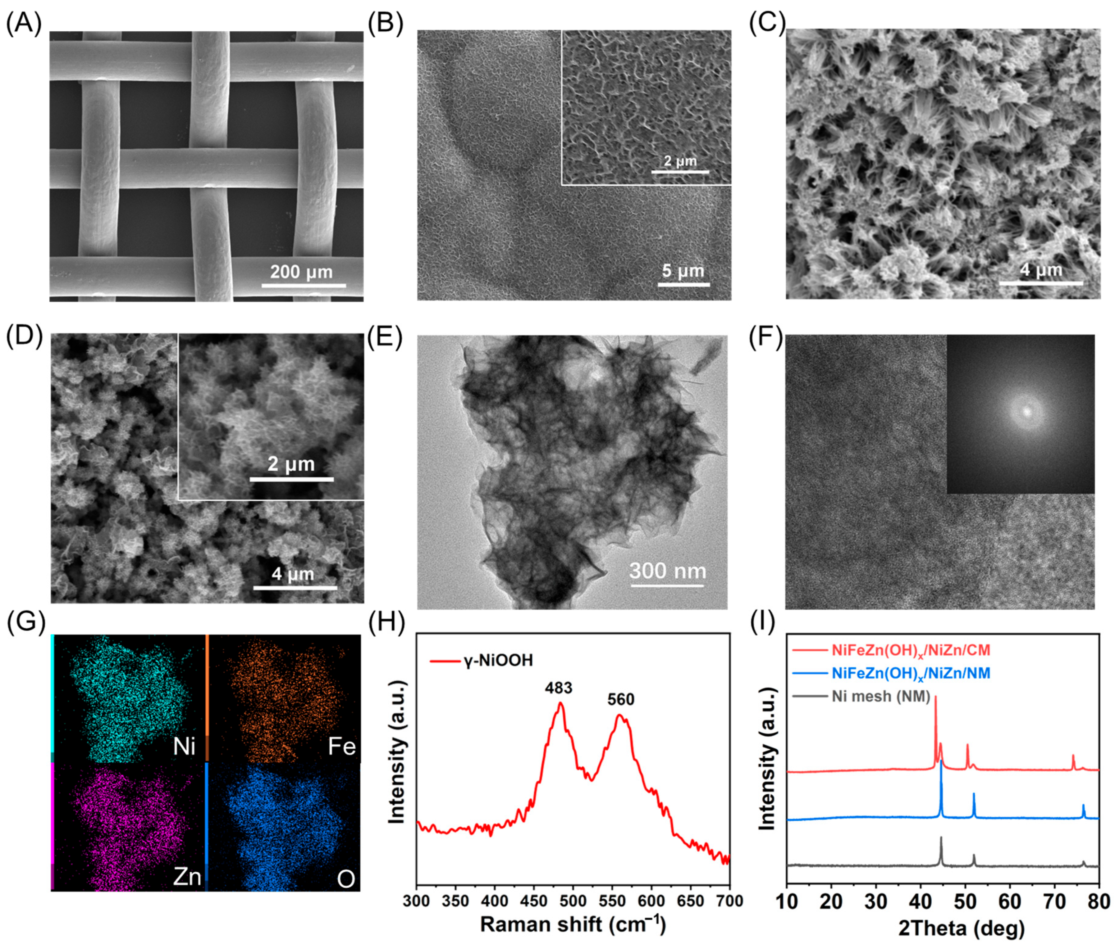
Figure 1A, the pristine NM exhibits a well-defined network structure composed of smooth nickel wires without discernible microstructural features. After electrodeposition, the surface becomes uniformly coated with a compact NiZn layer composed of densely stacked nanosheets (
Figure 1B). Subsequent alkaline etching dissolves most of the Zn species into the electrolyte, yielding an aggregated NiZn nanowire framework (
Figure 1C). This hierarchical nanowire architecture markedly increases the accessible surface area, providing abundant active sites and favorable anchoring positions for the growth of the NiFeZn(OH)
x catalytic layer.
During the chemical deposition process, the catalytic overlayer undergoes morphology reconstruction templated by the underlying NiZn scaffold, resulting in the formation of ultrathin nanosheets that uniformly cover the substrate (
Figure 1D). This reconstructed architecture greatly enlarges the specific surface area and exposes a high density of catalytically active sites, thereby enhancing the oxygen evolution reaction (OER) activity as expected. In contrast, the electrode prepared without Zn electroplating exhibits irregular spherical aggregates wrapped with nanosheets (
Figure S2). Although its chemically deposited overlayer appears similar to that of NiFeZn(OH)
x/NiZn/NM, the absence of the nanowire scaffold leads to a markedly reduced surface area, accounting for the inferior performance of NiFe(OH)
x/Ni/NM.
The TEM image of the catalyst on the NiFeZn(OH)
x/NiZn/NM electrode (
Figure 1E) clearly reveals its nanosheet morphology. In the high-resolution TEM image (
Figure 1F), no distinct lattice fringes are observed, and the SAED pattern displays no obvious diffraction rings, indicating that the catalyst is amorphous in nature. The elemental mapping (
Figure 1G) confirms the homogeneous distribution of Ni, Fe, Zn, and O, with an atomic ratio of Ni:Fe:Zn ≈ 1:2:2. Considering that Ni and Zn originate from the support while Fe derives from the deposition solution, it can be inferred that doping and morphological reconstruction yield a hydroxide phase composed of Ni, Fe, and Zn. To verify the presence of the oxidation layer after chemical oxidation, Raman spectra of the oxidized NiZn/NM electrode were collected. As shown in
Figure 1H, the characteristic peaks at 483 and 560 cm
−1 correspond to γ-NiOOH, confirming that the oxidation layer not only exhibits alkalinity but also oxidizes surface-contacting Fe
2+, thereby facilitating the successful incorporation of Fe into the catalytic layer. To examine whether the crystal structure of the supporting layer changes during electrode fabrication—while avoiding interference from the Ni substrate—a NiFeZn(OH)
x/NiZn/CM electrode was additionally prepared using a copper mesh as the substrate. As shown in the XRD patterns (
Figure 1I), both NM and NiFeZn(OH)
x/NiZn/NM electrodes exhibit only the characteristic diffraction peaks of metallic Ni, further confirming the amorphous nature of the catalytic layer. In contrast, the NiFeZn(OH)
x/NiZn/CM electrode shows diffraction peaks corresponding to metallic Cu and Ni, where Cu originates from the substrate and Ni from the electroplated layer, indicating that the crystalline Ni phase remains intact throughout electrode fabrication. Elemental mapping in the TEM image also reveals a relatively high content of Zn, suggesting that Zn remains distributed within the support after etching and oxidation. ICP measurements further corroborate this observation: the Ni:Zn ratio of the electroplated alloy is 1:1.73, which changes to 1:0.33 after etching, and to Ni:Fe:Zn = 1:0.11:0.17 after chemical deposition of NiFeZn(OH)
x/NiZn. These results indicate that Zn persists throughout the electrode preparation process, and its absence of diffraction peaks in XRD arises from either Zn incorporation into the Ni lattice or its existence in a non-crystalline configuration.
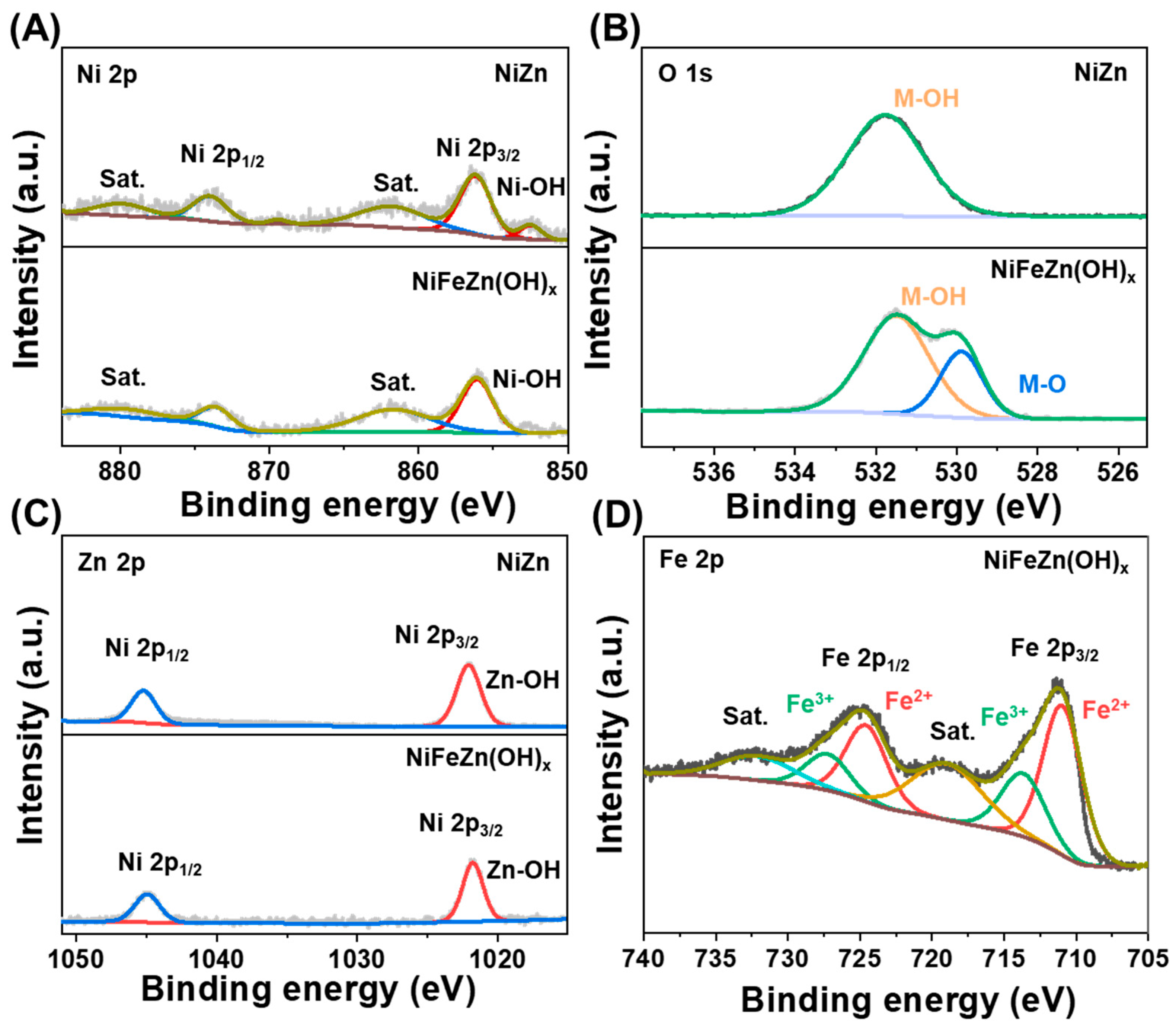
X-ray photoelectron spectroscopy (XPS) was conducted to elucidate the chemical states of elements within the NiZn substrate (
Figure 2,
Figures S3 and S4). As shown in the Ni 2p spectrum (
Figure 2A), the characteristic peaks at 856.18 and 874.02 eV correspond to Ni 2p
3/2 and Ni 2p
1/2 of Ni–OH, respectively. The O 1s spectrum (
Figure 2B) exhibits a dominant peak at 531.76 eV, assignable to hydroxyl oxygen species associated with metal oxides. In the Zn 2p spectrum (
Figure 2C), the peaks at 1022.03 and 1045.25 eV are attributed to Zn 2p
3/2 and Zn 2p
1/2 of Zn–OH, respectively. These results confirm the valence states of etched NiZn and suggest that the formation of a surface oxidation layer enables Fe incorporation and structural reconstruction during subsequent modification [
26,
27,
30,
31].
The surface chemistry of the as-prepared nanosheet-structured NiFeZn(OH)
x was further examined by XPS (
Figure 2,
Figures S5 and S6). In the Ni 2p spectrum (
Figure 2A), the peaks at 856.05 and 873.69 eV are characteristic of Ni–OH. The O 1s spectrum (
Figure 2B) shows two distinct peaks at 529.94 and 531.52 eV, corresponding to lattice oxygen (M–O) and hydroxide oxygen species, respectively. The Zn 2p spectrum (
Figure 2C) features two peaks at 1022.03 and 1045.35 eV, consistent with Zn–OH. In the Fe 2p spectrum (
Figure 2D), the peaks at 711.07/724.68 eV and 713.81/727.43 eV can be assigned to Fe
2+ and Fe
3+, respectively, confirming the coexistence of dual-valence iron species. Collectively, these XPS analyses unambiguously verify the oxidation states of Ni, Fe, and Zn, and substantiate the successful formation of the Fe-incorporated NiFeZn(OH)
x catalyst with a mixed-valence surface conducive to catalytic activity.
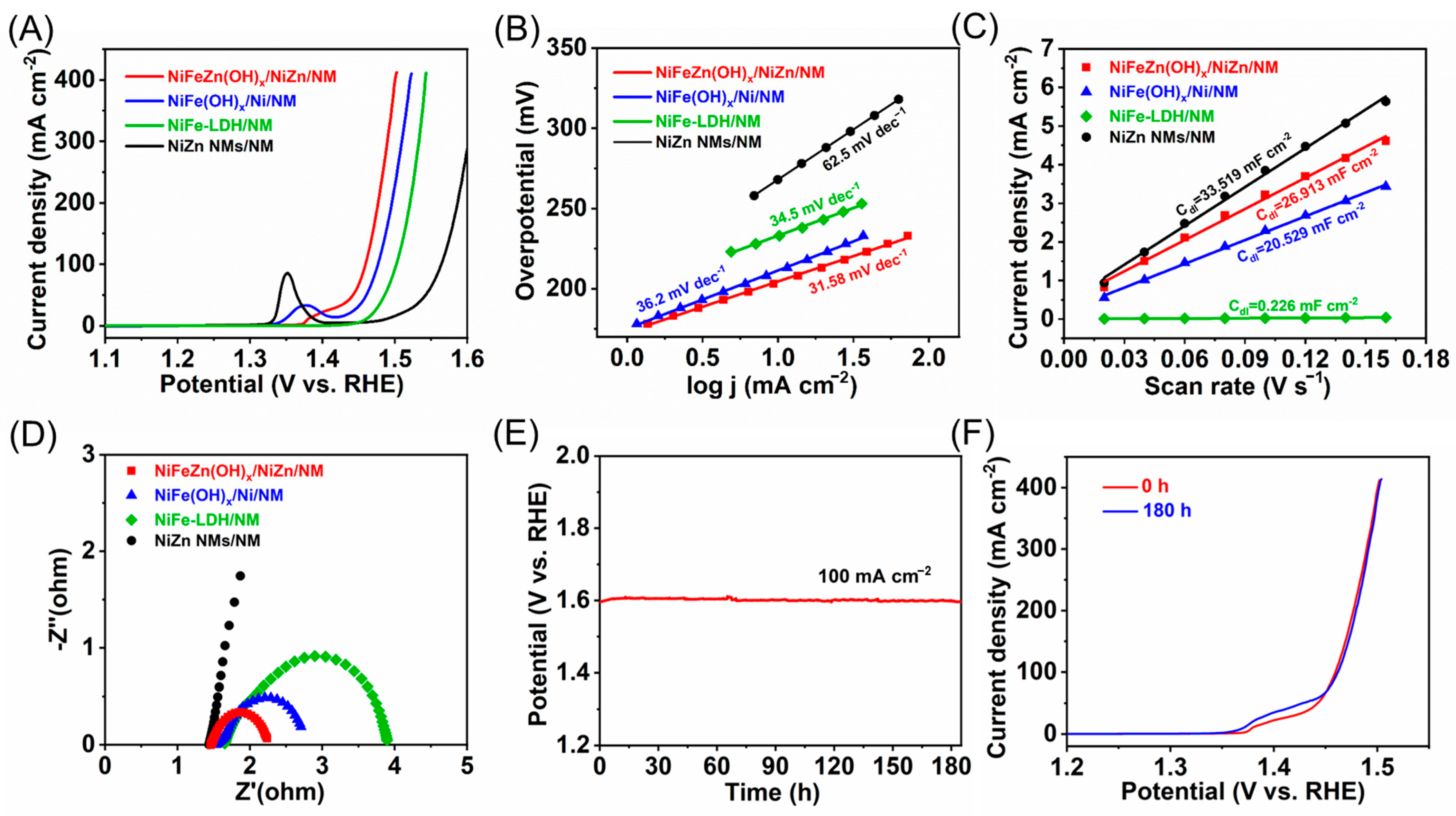
The electrocatalytic water oxidation performance of the as-prepared electrodes was systematically evaluated in 1.0 M KOH. The NiFeZn(OH)
x/NiZn/NM electrode exhibited exceptional OER activity, requiring an overpotential of only 229 mV to deliver 100 mA cm
−2 (
Figure 3A). In comparison, NiFe(OH)
x/Ni/NM, NiFe-LDH/NM, and NiZn/NM required 247, 273, and 334 mV, respectively. The corresponding Tafel slopes further confirmed the superior reaction kinetics of NiFeZn(OH)
x/NiZn/NM (31.6 mV dec
−1), which outperformed NiFe(OH)
x/Ni/NM (36.2 mV dec
−1), NiFe-LDH/NM (34.5 mV dec
−1), and NiZn/NM (62.5 mV dec
−1,
Figure 3B). These results collectively demonstrate that NiFeZn(OH)
x/NiZn/NM possesses the most favorable OER kinetics among all tested electrodes.
To elucidate the origin of the enhanced activity, electrochemically active surface area (ECSA) and electrochemical impedance spectroscopy (EIS) measurements were conducted. Cyclic voltammetry curves recorded at different scan rates in the non-Faradaic region (
Figure S7) were used to determine the double-layer capacitance (Cdl), yielding values of 26.913, 20.480, 0.226, and 33.519 mF cm
−2 for NiFeZn(OH)
x/NiZn/NM, NiFe(OH)
x/Ni/NM, NiFe-LDH/NM, and NiZn/NM, respectively (
Figure 3C). The corresponding ECSA values were calculated from the double-layer capacitance (Cdl) using a specific capacitance (C
s) of 0.040 mF cm
−2, giving 672.83, 512.00, 5.65, and 837.98 cm
2, indicating the relative abundance of exposed active sites. Although NiZn/NM exhibited the highest ECSA, its inherently poor intrinsic activity resulted in inferior OER performance. Conversely, NiFe-LDH/NM, despite its low ECSA, outperformed NiZn/NM owing to the intrinsically active Ni–Fe species. The performance trends of NiFeZn(OH)
x/NiZn/NM and NiFe(OH)
x/Ni/NM correlated well with their ECSA values, suggesting that the difference in active-site density primarily originates from their distinct supporting architectures, consistent with the SEM observations. Furthermore, to better quantify the electrochemically active surface area (ECSA), the double-layer capacitance (Cdl) values were converted using a specific capacitance (C
s) of 0.04 mF cm
−2 according to ECSA = Cdl/C
s. The calculated ECSA values are 627.83, 512.00, 5.65, and 837.96 cm
2 for NiFeZn(OH)
x/NiZn/NM, NiFe(OH)
x/Ni/NM, NiFe-LDH/NM, and NiZn/NM, respectively. The ECSA-normalized LSV curves (
Figure S8) further verify that NiFeZn(OH)
x/NiZn/NM possesses the highest intrinsic OER activity.
EIS measurements further corroborated these findings. The charge-transfer resistance (Rct) followed the order NiFeZn(OH)
x/NiZn/NM < NiFe(OH)
x/Ni/NM < NiFe-LDH/NM < NiZn/NM (
Figure 3D), indicating that NiFeZn(OH)
x/NiZn/NM possesses the most efficient charge-transfer capability. This superior conductivity can be attributed to the NiZn nanowire scaffold, which ensures intimate interfacial contact and abundant electron transport pathways. Consequently, the remarkable OER activity of NiFeZn(OH)
x/NiZn/NM arises from the synergistic effects of high active-site density and rapid charge transfer. Long-term durability tests (
Figure 3E) revealed negligible potential drift during continuous electrolysis at 100 mA cm
−2 for 180 h, with the electrode potential stabilizing at 1.599 V vs. RHE. The post-electrolysis LSV curve (
Figure 3F) nearly overlapped with the initial one, exhibiting only a 3 mV increase in overpotential (from 229 to 232 mV), confirming the outstanding long-term stability of NiFeZn(OH)
x/NiZn/NM under demanding OER conditions. For reference, the benchmark RuO
2 catalyst exhibits an overpotential of approximately 357 mV at 100 mA cm
−2 with a Tafel slope of 38–42 mV dec
−1 (
Figure S9). In comparison, the Tafel slope of 31.6 mV dec
−1 obtained in this work indicates superior reaction kinetics, suggesting a rate-determining step associated with a single-electron transfer process.
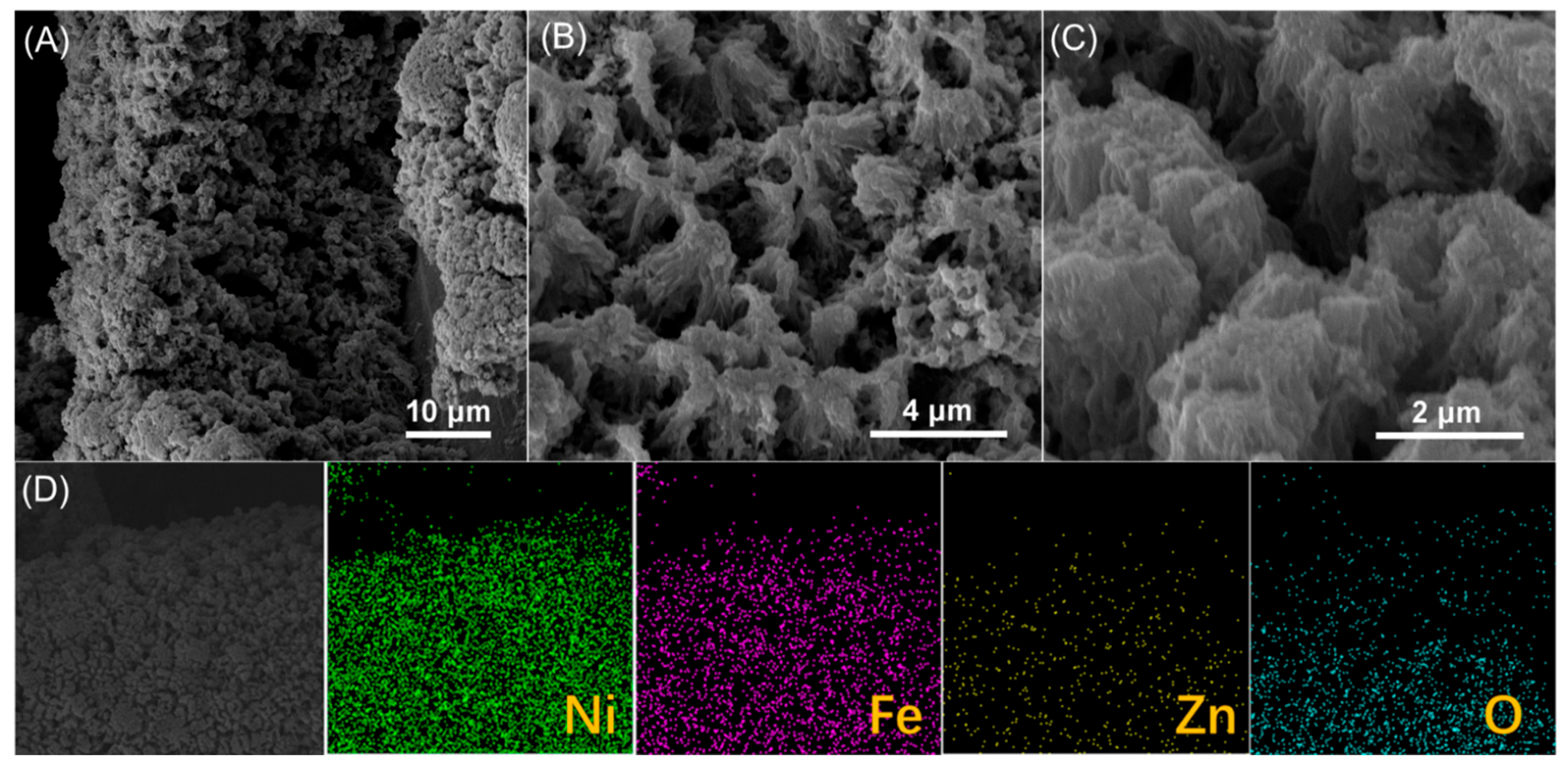
After continuous operation at a current density of 100 mA cm
−2 for 180 h, the NiFeZn(OH)
x/NiZn/NM electrode underwent pronounced morphological reconstruction (
Figure 4A–C). The nanosheet arrays originally decorating the support surface disappeared, giving rise to a dense, featureless layer in which remnants of the NiZn nanowires remained discernible. Elemental mapping (
Figure 4D) confirmed that Ni, Fe, Zn, and O remained homogeneously distributed, while ICP analysis revealed a Ni:Fe:Zn atomic ratio of approximately 1:0.10:0.13. Remarkably, despite these structural transformations, the catalytic activity remained virtually unchanged, indicating that the catalyst layer was not degraded but dynamically restructured under operating conditions.
This reconstruction is likely driven by further electrochemical leaching of Zn species, leading to the collapse of the initial nanosheet architecture and the subsequent redeposition of active components onto the NiZn scaffold. The resulting thinner catalytic layer establishes more intimate contact with the substrate while maintaining a high density of exposed active sites, thereby sustaining excellent OER performance. Such self-adaptive reconstruction underscores the dynamic stability of the catalyst and highlights the pivotal role of Zn-mediated restructuring in maintaining long-term electrocatalytic durability.


