Abstract
Plasma has become an up-and-coming advanced oxidation technology for wastewater treatment. However, its efficiency is often limited due to the lack of high-performance catalytic materials. In this study, one-dimensional carbon nanofiber precursors were first fabricated via electrospinning, followed by the in situ growth of the Zn/Fe-MOF on their surfaces. After pyrolysis at different temperatures, a series of carbon-based catalysts (FeNFC) were obtained. This new type of catalyst possesses advantages such as high porosity, a large specific surface area, and mechanical stability. Using tetracycline (TTCH) as the target pollutant, the performance of the catalyst was evaluated in the dielectric barrier discharge (DBD) system. The study showed that the addition of FeNFC significantly increased the degradation rate of TTCH in the system. Comparing different pyrolysis temperatures, at 900 °C, the comprehensive performance of the catalyst (FeNFC-900) was the best (the kinetic constant was kobs = 0.126 min−1, and the removal rate of TTCH was 91.8% within 30 min). The catalytic performance was influenced by factors such as the dosage of the catalyst, the concentration of TTCH, the power of DBD, and the initial pH. The catalytic effect of the material increased within a certain range with the increase in the catalyst dosage. The increase in TTCH concentration led to a decrease in the catalytic performance. The higher the power of the DBD, the higher the removal rate of TTCH. Moreover, when the initial pH was strongly alkaline, the catalytic effect of the catalyst was the best (kobs = 0.275 min−1, and the removal rate of TTCH was 98.7% within 30 min). Ionic interference tests demonstrated the strong resistance of FeNFC to common water matrix components, while radical quenching experiments revealed that multiple reactive species contributed to TTCH degradation. This work has broad application prospects for enhancing the efficiency of DBD systems in the removal of TTCH.
1. Introduction
In recent years, with the deepening of research, advanced oxidation processes (AOPs) have become a research and application hotspot due to their excellent degradation and mineralization capabilities for organic pollutants [1]. DBD plasma technology is a type of non-thermal plasma (NTP) technology which can generate various highly active substances such as hydroxyl radical ∙OH, H2O2, and O3 during the discharge process. At the same time, it also produces physical effects such as ultraviolet–visible light and shock waves. When treating wastewater, organic pollutants in water can be efficiently degraded with the help of these active substances and physical effects, thereby achieving the purpose of water purification [2,3]. Moreover, the integration of plasma in catalytic systems offers additional advantages—activating gas molecules, modifying catalyst surfaces to generate new adsorption active sites, and thereby creating new reaction paths [4]. Studies have shown that plasma advanced oxidation technology integrates the advantages of multiple advanced oxidation technologies and is an up-and-coming emerging wastewater treatment technology. In the actual treatment of wastewater, this technology not only has a very short processing time but also a fast degradation rate, without causing secondary pollution, and has significant advantages, thus generating extensive research [5,6,7,8]. However, the active substances and ultraviolet–visible light generated in the DBD system have not been efficiently developed and fully utilized. A considerable proportion of energy is converted into chemical energy, light energy, and ultrasonic energy, which leads to problems such as poor energy utilization and rapid electrode wear, reducing energy efficiency. Therefore, using catalysts to enhance the DBD plasma system is currently a very important research direction.
The combined use of DBD and highly efficient catalysts can significantly enhance the degradation efficiency of organic pollutants, while reducing energy loss and minimizing the generation of harmful by-products. This is the key to the wide application of DBD technology. Bimetallic catalysts can significantly increase the content of surface-active oxygen and oxygen mobility through the synergistic effect between two metals, demonstrating excellent catalytic activity. Research has found that the degradation efficiency of amoxicillin (AMX) antibiotic wastewater when adding ZnO/α-Fe2O3 catalyst in combination with the DBD is greatly enhanced from the original 75.0% to 99.3%. Moreover, the effluent from the system is non-toxic [9], but by-products such as N2O may still be generated during the reaction process. Carbon-based catalysts have a high atomic utilization rate and a unique electronic structure, which can increase the activation energy of the reaction. They are ideal catalytic materials for various reactions in the DBD system. Introducing iron–manganese-doped activated carbon (Fe-Mn/AC) catalytic materials for the synergistic degradation of TTCH wastewater can greatly improve the utilization efficiency of discharge energy. The removal rate of TTCH was increased by 25.5% in [10]. However, the conventional method for preparing carbon-based catalysts has problems such as cumbersome steps, low yield, poor universality, and poor thermal stability, which limit its application in the actual catalytic field. MOF materials possess high porosity, a large specific surface area, and adjustable pore structure. They also have certain thermal stability, chemical stability, and good biocompatibility [11,12,13]. The incorporation of highly active nano-metal particles into MOFs not only supplements the catalytic active sites but also optimizes the catalytic path through the synergistic effect with MOFs, significantly enhancing the comprehensive catalytic performance of the material. We used the in situ growth strategy to prepare a composite material, which enabled MOFs crystals to grow directionally on the surface of polymer fibers by precisely controlling the crystallization process, avoiding the problem of active site shielding caused by polymer coating in traditional methods.
Studies have shown that the in situ growth of MOFs can be achieved by blending metal salt with polymers and then immersing them in an organic ligand solution [14,15,16]. Electrospun nanofibers are microscale fibers fabricated via electrostatic forces, boasting high specific surface area and excellent mechanical strength [17,18]. Therefore, by combining electrospinning technology, metal ions are introduced into the interior of fibers, and then the fibers are immersed in the ligand solution. During this process, metal ions will spontaneously undergo binding reactions with the surrounding organic ligands. This promotes the growth of MOF crystals on the fiber surface and can regulate the morphology and structure of the fibers. By adjusting parameters such as the concentration of the spinning solution, voltage, and receiving distance, fibers with different diameters, porosities, and orientations can be prepared, providing diverse growth substrates for MOF crystals and achieving precise control over the microstructure of the material. This study aim to grow MOFs in situ onto the nanomaterial surface, integrating the advantages of a high specific surface area, high porosity, and good mechanical properties to exert a synergistic effect and achieve functional diversification [19,20]. The MOFs obtained through calcination can enhance their stability while maintaining the morphological characteristics and other properties of MOFs [21,22,23], so a catalyst was prepared by pyrolysis to work in synergy with the DBD system, thereby removing TTCH from water.
2. Results and Discussion
2.1. Characterization of the Catalysts
Figure 1a shows the scanning electron microscopy (SEM) image of the nanofiber morphology and microstructure. The electrospun nanofiber material precursor exhibited a smooth surface, uniform diameter, and was devoid of features such as pores, cracks, protrusions, or depressions. As shown in Figure 1b,c, the SEM images of ZIF-8@Fe revealed numerous small protrusions uniformly distributed on the nanofiber surface, indicating that Zn/Fe-MOF nanoparticles were uniformly loaded on the nanofiber. After pyrolysis, distinct morphological changes were observed (Figure 1d–f). The surfaces of FeNFC-800, FeNFC-900, and FeNFC-1000 were decorated with a large number of protrusions, whose size and distribution varied with the pyrolysis temperature. Compared with FeNFC-800, FeNFC-900 displayed less homogeneous protrusions, while FeNFC-1000 exhibited fewer but significantly larger surface aggregates. It can be inferred that during pyrolysis at 800 °C, part of the MOF structure likely began to decompose but did not fully transform, thus the surface protrusions still retained certain MOF characteristics. Upon pyrolysis at 900 °C, the Zn/Fe-MOF underwent further decomposition. Some metal atoms may have migrated and agglomerated, forming new protruding particles on the surface of the carbon nanofibers. The size and distribution of these protrusions may have become less homogeneous. At 1000 °C, larger aggregates of metal carbides or carbon nanoparticles may have emerged as protrusions. Meanwhile, some small protrusions may have vanished due to high-temperature sintering, leading to a relatively decreased number but larger size of the surface protrusions.
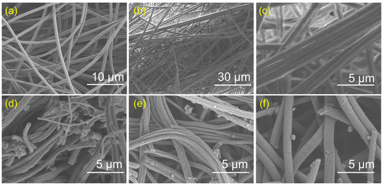
Figure 1.
(a) SEM images of nanofiber; (b,c) SEM and enlarged SEM images of the ZIF-8@Fe; (d–f) SEM images of FeNFC-800, FeNFC-900, and FeNFC-1000.
Figure 2a,b show the X-ray diffraction (XRD) patterns of the materials before and after carbonization. In Figure 2a, the unloaded MOF (i.e., nanofiber material) spectrum has no obvious sharp diffraction peaks, which may indicate an amorphous or low-crystallinity state. After loading the Zn/Fe-MOF (i.e., Nanofiber@Fe/ZIF-8), sharp and intense diffraction peaks appeared, which were characteristic diffraction peaks of the crystal structure of the Zn/Fe-MOF, indicating that a MOF with a specific crystal structure was successfully loaded. The Fourier transform infrared (FTIR) spectroscopy further verified these results (Figure S1). The peaks at 2923 cm−1 and 2243 cm−1 correspond to the C-H stretching vibration of methylene groups and the −CN stretching vibration in the polyacrylonitrile (PAN) backbone, respectively. They are the characteristic peaks of nanofibers. After loading the MOF, new absorption peaks appeared, including an absorption peak at 754 cm−1 attributed to metal–ligand vibrations, as well as characteristic peaks in the ranges of 1000–1500 cm−1 and 500–600 cm−1, which correspond to imidazole ring vibrations and Zn-N stretching vibrations, respectively. These results indicate that the Zn/Fe-MOF was successfully anchored to nanofiber precursors.
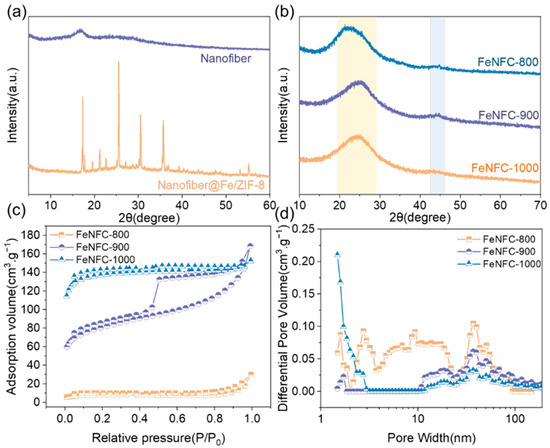
Figure 2.
(a,b) XRD diffraction patterns of nanofiber materials, nanofiber, Nanofiber@Fe/ZIF-8, and FeNFC-800/900/1000; (c) N2 adsorption/desorption isotherms of FeNFC-800/900/1000; (d) pore size distribution of FeNFC-800/900/1000.
Upon carbonization (Figure 2b), the crystal structure underwent a significant transformation. When carbonized at 800 °C, the material still had obvious diffraction peaks, indicating that carbonized products with certain crystallinity were formed at that time. As the temperature rose to 900 °C and 1000 °C, the position and intensity of the diffraction peaks changed, and the diffraction peaks gradually moved to a lower angle. These changes are likely attributed to atomic rearrangement and bond reorganization during high-temperature pyrolysis, leading to structural evolution of carbonized products. These changes highlight the temperature-dependent structural evolution of carbonized materials.
The specific surface area (SBET) and pore size distribution of FeNFC are shown after pyrolysis in Figure 2c,d and Table S1. As can be seen from Figure 2c, FeNFC exhibits type IV isotherms [24,25,26,27,28]. Under calcination at 900 °C, the hysteresis rings were obvious, with abundant and widely distributed mesopores. Under calcination at 1000 °C, the material had a high adsorption capacity, well-developed micropores, and a strong capillary condensation effect. It could be determined that the material was dominated by mesopores. Under the same relative pressure (P/P0) conditions, the adsorption volume value of FeNFC-1000 was significantly higher than that of FeNFC-800 and FeNFC-900. A higher adsorption volume means that FeNFC-1000 can absorb more gases. The pore size distribution diagram of Figure 2d confirms the porous structure of the material. Moreover, FeNFC-900 had multi-sized mesopores, which are suitable for the synergistic process of macromolecular degradation and pore adsorption.
2.2. Catalytic Performance
In a low-temperature plasma system, the catalytic enhancement effect of the prepared catalyst was evaluated based on the degradation kinetics of TTCH.
The adsorption capacity of the catalysts FeNFC-800, FeNFC-900, and FeNFC-1000 was about 1.5% (Figure S2), indicating that adsorption played an insignificant role and could be excluded from consideration in subsequent catalytic experiments.
The degradation of TTCH follows a pseudo-first-order kinetic model. As shown in Figure 3a and Figure S3, in the DBD system, the removal rate of TTCH within 30 min was only 88.2%, with a reaction rate constant of 0.099 min−1. Carbonizing the catalyst without MOF loading at 900 °C (unloaded MOF-900) significantly inhibited the reaction, reducing the rate constant of TTCH to only 0.085 min−1. Interestingly, the catalyst doped with the Zn/Fe-MOF significantly accelerated the degradation of TTCH, achieving a degradation rate of 91.8%. As the pyrolysis temperature increased, the degradation rate of TTCH by FeNFC gradually increased. However, the effects on the system under pyrolysis conditions of 900 °C and 1000 °C were approximately the same. Considering the energy consumption, cost, and catalytic effect of the materials in the pyrolysis process, it was decided to select carbon nanofiber materials with a pyrolysis temperature of 900 °C and loaded with the Zn/Fe-MOF (FeNFC-900) for the exploration of subsequent experiments.
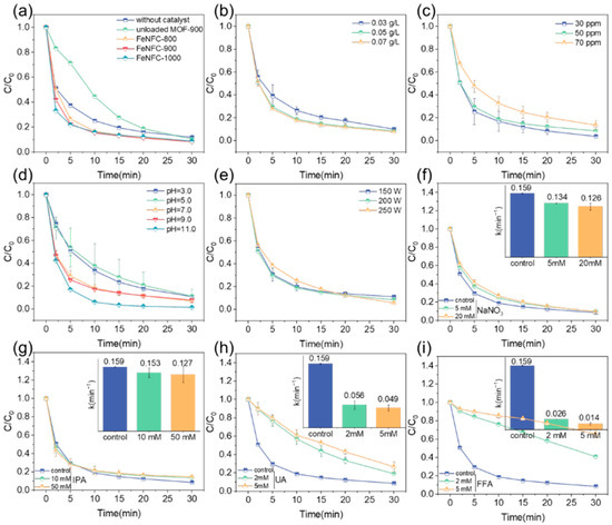
Figure 3.
Effect of experiment condition on TTCH degradation for (a) different catalysts; (b) dosage of the catalyst; (c) initial concentration of TTCH; (d) initial pH and (e) discharge voltage. Degradation behavior and kinetic constant of FeNFC-900 with (f) NaNO3, (g) IPA, (h) UA, and (i) FFA. Reaction condition: [pollutant] = 50 mg L−1, [catalyst] = 0.05 g L−1.
Reaction kinetics were further influenced by catalyst dosage, pollutant concentration, solution pH, and plasma power (Figure 3b–e). Figure S4 demonstrates that the degradation rate of TTCH increased gradually with the increase in FeNFC-900 dosage. The removal rates of TTCH were not significantly different at 0.03 g/L, 0.05 g/L, and 0.07 g/L, being as high as 90.0%, 91.6%, and 92.4%, respectively. However, with the increase in catalyst dosage, the kobs values also increased gradually to 0.125 min−1, 0.159 min−1, and 0.166 min−1, respectively. This enhancement can be attributed to the increased number of exposed Fe/N active sites, which facilitate more efficient electron transfer between the plasma-generated energetic electrons and dissolved oxygen, thereby promoting the generation of reactive oxygen species (ROSs).
Illustrated in Figure S5, the catalytic effect of the material gradually weakened with the increase in TTCH concentration, and the kobs values of TTCH concentrations were 0.180 min−1, 0.159 min−1, and 0.109 min−1 when the TTCH concentrations were 30 ppm, 50 ppm, and 70 ppm, respectively, showing a decrease with the increase in the concentration of TTCH, indicating that the degradation rate of TTCH slowed. The catalytic effect was best at a concentration of 30 ppm TTCH, with a TTCH removal rate of up to 96.3%. At a concentration of 70 ppm, the removal rate of TTCH was 86.5%, and the degradation effect was poor. As the concentration increased, the excessive TTCH molecules competed for the limited active species, leading to incomplete oxidation, which ultimately lowered the apparent kinetic constant and overall degradation efficiency.
The initial pH level significantly influences the degradation of TTCH [29]. As such, variations in the initial pH of the solution were assessed to quantify this effect. As shown in Figure S6, the kobs values were 0.11 min−1, 0.10 min−1, 0.16 min−1, 0.17 min−1, and 0.28 min−1 at pH 3.0, 5.0, 7.0, 9.0, and 11.0, respectively. Strong alkaline conditions have a better effect on the catalytic degradation of TTCH, while acidic conditions inhibit the degradation effect of the catalyst. The above results show that FeNFC-900 can be used with a wide range of pH and has good catalytic performance. The initial pH of the TTCH solution was measured at 6.85, which was close to neutral conditions. Considering the cost of the experiment and the degradation performance of the material under different pH conditions, the initial pH value of the system was not adjusted in the experiment, that is, the initial pH of the experimental system was 6.85.
As shown in Figure S7, the removal efficiency of TTCH increased with the increase in discharge power. Interestingly, in the initial stage of the reaction, the reaction rate constants of TTCH under 150 W and 200 W were higher than those under 250 W. This may be because the catalyst, as a black flake or powder substance, blocked part of the light, leading to a decrease in degradation efficiency. The results showed that the degradation rate of TTCH was the fastest at 200 W and the slowest at 250 W, but the final removal rate of TTCH was the highest. Increasing the input power can be regarded as raising the system’s input voltage. Consequently, in the DBD plasma–catalyst system, a higher input power enables the generation of more intense UV/visible light and a greater quantity of e−. This, in turn, promotes the production of reactive oxygen species (ROSs) and enhances reaction efficiency [30,31]. Considering the energy consumption and the degradation effect of the catalyst, the DBD plasma system experimented with a power of 200 W.
To enhance the practical relevance of our study, we connected research on antibiotic degradation to the broader challenge of halogenated organic pollutants (HOPs) in actual wastewater. We investigated the degradation behavior of TTCH in the presence of 4-chlorophenol. It can be seen from Figure S8 that FeNFC-900 exhibited excellent catalytic activity in the degradation process, even in the presence of 4-chlorophenol. After the addition of FeNFC-900, the removal efficiency of pollutants in the system increased from 46.7% to 84.5% It significantly boosted both reaction kinetics and final removal rate, validating its potential for treating complex wastewater containing multiple pollutants.
To verify the presence of radicals in the reaction of the catalyst with the DBD plasma system and explore their types, we conducted experiments, whose results are shown in Figure 3f–i. Since NaNO3 can quench hydrated electrons, isopropanol (IPA) can quench hydroxyl radicals, uric acid (UA) can quench active nitrogen, and furfuryl alcohol (FFA) can quench singlet oxygen. As can be seen from Figure 3f, the addition of NaNO3 had a certain inhibitory effect on the adsorption of TTCH by catalytic materials, but it was not obvious, and the degradation rate of TTCH slowed down, but the removal rate of TTCH remained at about 90%, indicating that eaq− had no major effect. Figure 3g shows that the degradation rate of TTCH was slower when IPA at 10 mM and 50 mM was added, but the removal rate still reached more than 85%, indicating that ∙OH was not the group playing a major role. In Figure 3h and Figure 3i, the addition of UA and FFA had an inhibitory effect on the degradation of TTCH; with the addition of 2 mM and 5 mM uric acid, the kobs was 0.056 min−1 and 0.049 min−1, respectively, and with the addition of 2 mM and 5 mM furfuryl alcohol, kobs was 0.026 min−1 and 0.014 min−1, respectively. The kobs of the non-quencher was 0.159 min−1, which was about 3 times that of the urea group and 10 times that of the furfuryl alcohol group. When 2 mM and 5 mM uric acid were added, the removal rates of TTCH in the system were 73.4% and 81%, respectively, and when 2 mM and 5 mM furfuryl alcohol were added, the removal rates of TTCH in the system were only 59.1% and 37.5%, respectively. The results showed that reactive nitrogen species (RNS) and singlet oxygen played a major role in the degradation of TTCH in the system.
The material cyclic degradation performance test can assess the material’s ability to remove pollutants during multiple uses. As shown in Figure 4, the pollutant removal rate slightly decreased with an increase in the number of cycles, but it remained above 85% in all five cycles. After five cycles, the material could still effectively degrade TTCH, indicating that the activity attenuation of FeNFC-900 during the cycle was small and fully demonstrated that the material had excellent reusability.
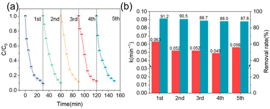
Figure 4.
Reusability of FeNFC-900 in TTCH degradation. (a) Degradation profiles over five consecutive cycles; (b) apparent rate constants and removal efficiencies in each cycle.
2.3. Degradation Mechanism Analysis
In an actual water environment, the composition is intricate. To delve into the influence mechanism of ions in water bodies on the degradation of target pollutants by the catalytic system, an ion interference experiment was performed. This study chose Cl−, HCO3−, H2PO4−, which are prevalent in water environments, and macromolecular humic acid (HA) as interfering substances.
We observed that low concentrations of Cl− exerted a negligible influence on TTCH degradation. However, as the Cl− concentration increased, kobs gradually decreased, indicating a partial inhibition of the degradation rate. Notably, this inhibitory effect had little impact on the final removal efficiency (Figure 5a). The addition of HCO3− promoted the degradation of TTCH, and with the increase in HCO3− concentration, kobs gradually increased, and the degradation rate of TTCH also increased, but the k value of HCO3− at different concentrations was not much different, with little effect on the degradation effect. This may be related to the fact that HCO3− binds the hydrogen ion H+ in the water, which reduces the concentration of hydrogen ions in the water and at the same time generates hydroxide ion OH−, which makes the water alkaline and the pH value increase (Figure 5b). The catalytic effect of the material was reduced with the addition of H2PO4−. It had a certain inhibitory effect on the degradation efficiency and removal rate of TTCH (Figure 5c). As can be seen from Figure 5d, when 50 mg/L HA was added, the degradation rate and removal rate of TTCH were significantly inhibited, and the removal rate was only 80%, while when 5 mg/L or 20 mg/L HA was added, the degradation rate of TTCH was not greatly affected, and the removal rate was above 90%, which indicated that the structure of FeNFC-900 enhanced the anti-interference ability of the system against ionic interferences and macromolecular interferences to a certain extent. According to the above results, FeNFC-900 can be used as a catalyst. Combined with the DBD plasma system, the low concentration of ionic interferences would not affect the experiment, and the material has good anti-interference ability.
OH + Cl− → HOCl−
∙OH + HCO3− → CO32− + H2O
∙OH + H2PO42− → HPO42− + H2O
HPO42− + ∙OH → PO43− + H2O
−COOH + ∙OH− → −COO− + H2O
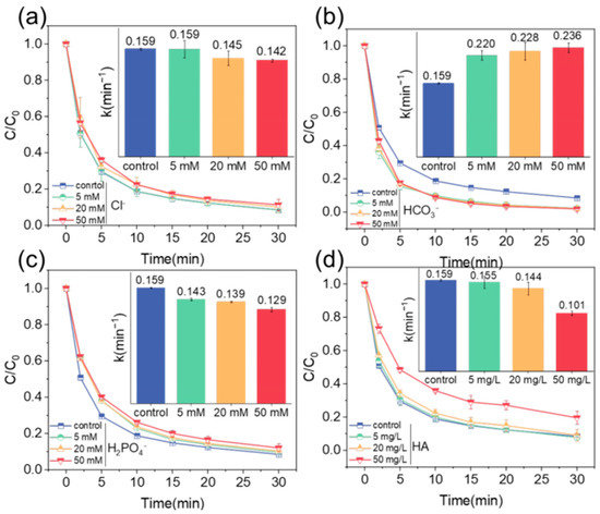
Figure 5.
Ionic interference resistance experiment: degradation behavior and kinetic constant of FeNFC-900 with (a) Cl−; (b) HCO3−; (c) H2PO4−; and (d) HA. Reaction conditions: [TTCH] = 50 mg L−1, [FeNFC-900] = 0.05 g L−1, [pH] = 7.0, [discharge voltage] = 200 W.
Finally, the degradation performance of TTCH was further evaluated in real water matrices, including tap water and lake water (Figure S9). It was found that the removal rate of TTCH decreased to 86.3% in tap water and 85% in lake water. Compared with the 91.6% removal rate of deionized water, the removal rate only decreased by less than 10%. This reduction can be attributed to the presence of coexisting ions and natural organic matter (NOM) [32]. Specifically, Cl− ions can react with highly oxidative species generated by the plasma, such as ∙OH, forming less reactive radicals like Cl2∙− (E° = 2.0 V) and Cl∙ (E° = 2.4 V), thereby suppressing the degradation process. In addition, humic acids (HAs) and other NOM components may compete with TTCH for reactive species or adsorb onto the catalyst surface, further reducing the effective degradation. These results highlight the importance of considering ionic composition and organic matter when evaluating the practical applicability of FeNFC catalysts in real water systems.
2.4. Degradation Pathway and Toxicity Analysis
Liquid Chromatography-Mass Spectrometry (LC-MS) and Density Functional Theory (DFT) analysis were used to analyze the degradation process. The mass spectra and possible degradation products are shown in Figure 6a and Figure S10, respectively. IN Figure 6a, mass spectrometry and structural analysis clarify the degradation pathways of TTCH. In LC-MS and DFT analyses, the degradation of TTCH can be classified into three main modes [33,34,35]:
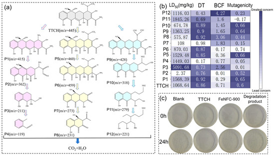
Figure 6.
(a) Possible degradation pathways of TTCH in the FeNFC-900/DBD system, (b) LD50, development toxicity, bioconcentration factor, and mutagenicity of TTCH and degradation byproducts; (c) digital images of the antibacterial experiment blank, undegraded TTCH, catalyst FeNFC-900, and degraded TTCH products.
- (1)
- TTCH first undergoes a demethylation reaction, losing one methyl group (−CH3) to form P1 (m/z = 415); it is speculated that two methyl groups or one methyl group are simultaneously removed. Subsequently, the amide bond of P1 breaks, possibly losing the carbonyl-containing fragment, and is transformed into P2 (m/z = 362). P2 further undergoes a ring-opening reaction of the ring structure, with the larger aromatic ring or heterocyclic ring breaking and losing the polyatomic group (molecular weight of approximately 151), generating P3 (m/z = 211). Ultimately, P3 undergoes the shedding of carboxyl or hydroxyl groups (such as −COOH, with a molecular weight of 45) to form P4 (m/z = 119) and further mineralizes.
- (2)
- TTCH first undergoes a hydroxylation reaction, introducing a hydroxyl group to form P5 (m/z = 460, possibly accompanied by methyl substitution). P5 then undergoes a dehydrogenation reaction, losing one hydrogen atom (−H, molecular weight 1) and converting to P6 (m/z = 459). P6 undergoes glycosidic bond cleavage or side chain shedding, losing a larger fragment (with a molecular weight of approximately 186) and generating P7 (m/z = 273). P7 continues to undergo deamination reaction (−NH2, molecular weight 16) or decarboxylation reaction, losing small molecule groups, generating P8 (m/z = 231), and eventually gradually mineralizes.
- (3)
- TTCH undergoes deamination first, generating P9 (m/z = 428). P9 then undergoes ring structure cleavage and may lose the nitrogen-containing heterocyclic fragment (with a molecular weight of approximately 110), transforming into P10 (m/z = 318). P10 loses a group with a molecular weight of approximately 39 through either bond breakage or alkyl chain shedding, generating P11 (m/z = 279). P11 further undergoes dehalogenation or demethylation reactions, generating P12 (m/z = 221), which is ultimately completely degraded into inorganic small molecules.
Intermediate products generated during the degradation process were characterized using three-dimensional excitation–emission matrix (3D-EEM) fluorescence spectroscopy, and organic pollutants’ transfer and degradation processes could be deduced from the fluorescence regions and intensity changes [36]. As shown in Figure S11. When the reaction time was 5 min, 10 min, 20 min, and 30 min, the reaction mixture in the degradation process was subjected to three-dimensional fluorescence detection to analyze the degradation mechanism of TTCH degradation. The fluorescence intensity was mainly distributed in regions III, IV, and V. The fluorescence intensity in the III and IV regions increased gradually with the increase in degradation time, which was related to the production of small-molecule fluorescent substances and protein-like substances during the degradation of organic matter and the influence of HA-like substances in water. The fluorescence intensity in region V gradually decreased, indicating that after 30 min of degradation, the molecular structure of TTCH was gradually destroyed, and the fluorescence characteristics changed. This means that the TTCH or its degradation intermediate products corresponding to this region decreased, and the degradation effect was better.
Toxicity assessment software testing (T.E.S.T., version 5.1) was used to evaluate the biological toxicity of TTCH and its degradation intermediates. In rats, with oral degradation intermediates, the 50% lethal dose (LD50), mutagenicity, developmental toxicity, and bioconcentration factor (BCF) are shown in Figure 6b. Both P3 and P4 exhibited relatively low developmental toxicity. P3 exhibited a lower mutagenicity and a lower risk of death in mice. In addition, we thoroughly combined the degraded solution, the undegraded TTCH solution, and the catalyst (FeNFC-900) solution into an Escherichia coli culture medium to detect the effect of each solution on bacterial growth. As shown in Figure 6c, except for the group with added TTCH, more colonies grew in the other three groups. This indicates that the FeNFC-900 catalyst had relatively low microbial toxicity, and the toxicity of the treated TTCH digestion liquid was also significantly reduced.
3. Materials and Methods
The materials used in the experiment, and the operation steps of the experiment are all shown in Texts S1–S3.
3.1. Experimental Setup
The DBD plasma reactor was primarily composed of three components: a high-voltage electrode, a grounded electrode, and a quartz tank. The quartz tank had an inner diameter of 80 mm, an outer diameter of 95 mm, and a height of 15 mm. A quartz plate with a diameter of 90 mm and a thickness of 2 mm was placed above the quartz tank. Specifically, the quartz tank served as the reaction zone for the reaction solution, while the circulation of the reaction solution was achieved using a peristaltic pump. The plasma was stimulated by a high-voltage AC power source to generate plasma in the gap between the quartz sheet and the water surface.
3.2. Energy Yield Analysis
The energy yield (EY) is the mass of a TTCH degradation unit of energy consumed as shown in Equation (6):
G50 is the energy efficiency of the degradation process when the TTCH concentration is reduced to 50% of the initial concentration as in Equation (7).
where C0 is the initial concentration of TTCH, is the TTCH degradation efficiency, P is the input power, V is the treatment volume, and t is the treatment time. Figure S12 shows the energy efficiency of different systems at 30 min. The combination system of DBD and catalysts generates higher energy efficiency than the DBD system alone, among which the energy efficiency of FeNFC-900 material is superior to other systems.
3.3. Synthesis of ZIF-8@Fe
Briefly, 0.2 g of iron acetylacetone (Fe(acac)3) and 0.2 g of zinc acetate (Zn(OAc)2) were dissolved in 15 mL of N,N-dimethylformamide (DMF), and then 2 g of polyacrylonitrile (PAN) was added. After ultrasonic shaking, the mixture was placed in a thermostatic magnetic stirrer at 60 °C and stirred for 9 h. The prepared solution was loaded into a 10 mL syringe tube, and under the high pressure of 18.00 kV of the high-speed drum spinning machine, the solution eventually fell onto the collection device, forming a nanofibrous aggregate material. Subsequently, 1.82 g of 2-methylimidazole was dissolved in 200 mL of deionized water, and the spun material was allowed to soak in the solution for 24 h. After that, the material was taken out and dried, yielding the precursor material ZIF-8@Fe.
3.4. Synthesis of FeNFC
The drying material was placed in a tube furnace, heated to the required temperature (800 °C, 900 °C, 1000 °C) and insulated for 2 h under the protection of a nitrogen atmosphere. After natural cooling, carbon nanofibers loaded with the Zn/Fe-MOF were prepared. They were used after grinding them into a powder. The resulting black powder constituted the nitrogen-doped carbon material derived from ZIF-8, designated as FeNFC. Based on the respective calcination temperature, the synthesized materials were assigned to the nomenclature FeNFC-800, FeNFC-900, and FeNFC-1000. In addition, the nanofibrous was carbonized separately and designated as NFC-900.
3.5. Experimental Methods
A 100 mL volume of TTCH solution (50 ppm) was first prepared. Subsequently, the stirrer was activated, and the stirring speed of the solution was adjusted to 550 r/min. An ultraviolet spectrophotometer was employed to determine the initial absorbance of the solution at a wavelength of 360 nm. Following this, 5 mg of the catalyst was added to the solution, and timing was initiated concurrently while the DBD system was activated to initiate the degradation process. At predetermined time intervals, 2 mL aliquots of the reaction solution were collected and filtered through a 0.22 μm organic phase filter membrane to remove catalyst particles. The absorbance of the filtered samples was measured using the identical protocol applied for the initial absorbance determination. Based on the obtained absorbance values, the residual ratio of TTCH (the target pollutant) in the solution under the DBD system was calculated, which was further used to evaluate the catalytic performance of the as-used material. We used the experimental setup by integrating a thermostatic water bath with precise temperature control to maintain a stable 30 °C environment. All experimental procedures were conducted in triplicate to ensure the reliability and reproducibility of the results.
4. Conclusions
In this experiment, a nanofiber material containing iron ions and zinc ions collected by electrospinning was synthesized. Through an in situ growth strategy, a Zn/Fe-MOF was loaded on its surface. Carbon nanofiber material FeNFC was prepared by pyrolysis at high temperature. Combined with a DBD plasma advanced oxidation system, it hardly adsorbed TTCH in water. Its uniformly distributed Fe/Zn ions provided nucleation sites for the in situ growth of the Zn/Fe-MOF, avoiding the uneven loading of MOFs that often causes active site aggregation. It had excellent anti-adsorption capacity, and the catalytic effect became better with the increase in pyrolysis temperature, catalyst dosage, and power of DBD. The degradation effect was best when the pH was strongly alkaline. The quenching experiment confirmed that the main highly ROSs in the experimental system were RNS and singlet oxygen. FeNFC showed unique adaptability; when HCO3− was present, it significantly promoted the degradation of TTCH and only high concentrations of HA (>50 mg/L) inhibited degradation, while low concentrations almost had no effect. The material had good anti-interference ability. Cyclic experiments showed that after three rounds of cycling, the material could still maintain excellent catalytic performance, which indicates that it has good reusability. Toxicological experimental tests proved that FeNFC material was environmentally friendly. Overall, these findings highlight that FeNFC is a promising and environmentally friendly catalyst for plasma-based AOPs.
Supplementary Materials
The following supporting information can be downloaded at: https://www.mdpi.com/article/10.3390/catal15100944/s1, Text S1: Chemicals; Text S2: Characterization; Text S3: Experiment of ion interference; Table S1: The content of SBET, Vpore and the pore size; Table S2: Several intermediates and the m/z values detected by LC-MS; Figure S1: The FTIR spectra of nanofiber materials and ZIF-8@Fe; Figure S2: The adsorption capacity: (a) adsorption diagram of the catalysts FeNFC-800, FeNFC-900 and FeNFC-1000; (b) reaction rate and adsorption capacity; Figure S3: The kinetic constants and removal rates of different catalysts; Figure S4: The kinetic constants and removal rates at different dosages of the catalyst; Figure S5: The kinetic constants and removal rates at different initial concentrations of TTCH; Figure S6: The kinetic constants and removal rates at different initial pH values; Figure S7: The kinetic constants and removal rates at different discharge voltages; Figure S8: The degradation behavior, kinetic constant and removal rates of FeNFC-900 in the presence of 4-Chlorophenol; Figure S9: Effect of different aqueous solutions on TTCH degradation; Figure S10: The MS results of intermediates; Figure S11: The 3D EEM fluorescence spectra of degradation products; Figure S12: Energy efficiency of different systems at 30 min.
Author Contributions
Writing—original draft preparation, Y.X. and S.T.; methodology, Y.L.; formal analysis, C.Z.; supervision, W.Q. and S.C.; writing—review and editing, J.R. and M.Z.; resources, C.G. All authors have read and agreed to the published version of the manuscript.
Funding
This work was financially supported by National Natural Science Foundation of China (52300048); China Postdoctoral Science Foundation (2023M741627).
Data Availability Statement
Data will be made available on request.
Conflicts of Interest
The authors declare no conflicts of interest.
References
- Deng, J.; Feng, S.; Ma, X.; Li, J.; Gao, N. Research Progress on Advanced Oxidation Technology of Homogeneous activated peroxymonosulfate. Technol. Water Treat. 2015, 41, 13–19. [Google Scholar]
- Wang, Q.; Wang, T.; Qu, G.; Zhang, Y.; Sun, Q.; Guo, X.; Jia, H. High-efficient removal of tetrabromobisphenol A in aqueous by dielectric barrier discharge: Performance and degradation pathways. Sep. Purif. Technol. 2020, 240, 116615. [Google Scholar] [CrossRef]
- Liu, X. Research on the Application of Surface Plasma Resonance Technology in Environmental Pollutant Monitoring. Low Carbon World 2016, 9, 19–20. [Google Scholar]
- Meloni, E.; Cafiero, L.; Renda, S.; Martino, M.; Pierro, M.; Palma, V. Ru- and Rh-Based Catalysts for CO2 Methanation Assisted by Non-Thermal Plasma. Catalysts 2023, 13, 488. [Google Scholar] [CrossRef]
- Fan, Z. Pilot Study on the Treatment of Printing and Dyeing Wastewater by Dielectric Barrier Discharge Plasma. Master’s Thesis, Taiyuan University of Technology, Taiyuan, China, 2021. [Google Scholar]
- Shi, C.; Wang, S.; Ge, X.; Deng, S.; Chen, B.; Shen, J. A review of different catalytic systems for dry reforming of methane: Conventional catalysis-alone and plasma-catalytic system. J. CO2 Util. 2021, 46, 101462. [Google Scholar] [CrossRef]
- Feng, J.; Sun, X.; Li, Z.; Hao, X.; Fan, M.; Ning, P.; Li, K. Plasma-assisted reforming of methane. Adv. Sci. 2022, 9, 2203221. [Google Scholar] [CrossRef]
- Andersen, J.A.; Christensen, J.M.; Østberg, M.; Bogaerts, A.; Jensen, A.D. Plasma-catalytic dry reforming of methane: Screening of catalytic materials in a coaxial packed-bed DBD reactor. Chem. Eng. J. 2020, 397, 125519. [Google Scholar] [CrossRef]
- Ansari, M.; Mahvi, A.H.; Salmani, M.H.; Sharifian, M.; Fallahzadeh, H.; Ehrampoush, M.H. Dielectric barrier discharge plasma combined with nano catalyst for aqueous amoxicillin removal: Performance modeling, kinetics and optimization study, energy yield, degradation pathway, and toxicity. Sep. Purif. Technol. 2020, 251, 117270. [Google Scholar] [CrossRef]
- Cheng, J.; Xie, Y.; Wei, Y.; Xie, D.; Sun, W.; Zhang, Y.; Li, M.; An, J. Degradation of tetracycline hydrochloride in aqueous via combined dielectric barrier discharge plasma and Fe-Mn doped AC. Chemosphere 2021, 286, 131841. [Google Scholar] [CrossRef]
- Li, W.; Zhang, Y.; Li, Q.; Zhang, G. Metal−organic Framework Composite Membranes: Synthesis and Separation Applications. Chem. Eng. Sci. 2015, 135, 232–257. [Google Scholar] [CrossRef]
- Hong, D.H.; Shim, H.S.; Ha, J.; Moon, H.R. MOF-on-MOF Architectures: Applications in Separation, Catalysis, and Sensing. Bull. Korean Chem. Soc. 2021, 42, 956–969. [Google Scholar] [CrossRef]
- Lou, X.; Zhi, F.; Sun, X.; Wang, F.; Hou, X.; Lv, C.; Hu, Q. Construction of co-immobilized laccase and mediator based on MOFs membrane for enhancing organic pollutants removal. Chem. Eng. J. 2023, 451, 138080. [Google Scholar] [CrossRef]
- Niu, F.; Sun, Y.; Yang, S.; Wang, J.; Mi, J.; Feng, Y. Research Progress on the Purification of Gas Pollutants by MOFs/Electrospun Nanofibers and Their Derivative Materials. Chem. Ind. Eng. Prog. 2024, 1–21. [Google Scholar] [CrossRef]
- Hu, L.; Bui, V.T.; Pal, S.; Guo, W.; Subramanian, A.; Kisslinger, K.; Fan, S.; Nam, C.Y.; Ding, Y.; Lin, H. In Situ Growth of Crystalline and Polymer-Incorporated Amorphous ZIFs in Polybenzimidazole Achieving Hierarchical Nanostructures for Carbon Capture. Small 2022, 18, 2201982. [Google Scholar] [CrossRef]
- Xiao, W. Preparation and Performance Study of In-Situ Grown ZIF-8 Reinforced, Toughened and Self-healing Materials. Master’s Thesis, Beijing University of Chemical Industry, Beijing, China, 2024. [Google Scholar]
- Zhang, H.; Zhao, B.; Wang, H.; Wang, J.; Teng, Y.; Sun, Y.; Li, Y.; Wang, C. Water-/Oil-repellent polyacrylonitrile nanofiber air filter modified with silica nanoparticles and fluorine compounds. ACS Appl. Nano Mater. 2022, 5, 8131–8141. [Google Scholar] [CrossRef]
- Huang, H.; Song, Y.; Zhang, Y.; Li, Y.; Li, J.; Lu, X.; Wang, C. Electrospun nanofibers: Current progress and applications in food systems. J. Agric. Food Chem. 2022, 70, 1391–1409. [Google Scholar] [CrossRef]
- Sadakiyo, M. Support effects of metal–organic frameworks in heterogeneous catalysis. Nanoscale 2022, 14, 3398–3406. [Google Scholar] [CrossRef] [PubMed]
- Meng, J. Based on ZIF-67 Derived Carbon Materials Preparation and Dye Adsorption Study. Master’s Thesis, Changchun University of Technology, Changchun, China, 2025. [Google Scholar]
- Guo, S.; Li, Z.; Li, Y.; Zeng, Z.; Lv, J.; Huang, S.; Wang, Y.; Ma, X. CoMn catalysts derived from partial decomposed layered CoMn-MOF materials for higher alcohol synthesis from syngas. Chem. Eng. J. 2023, 463, 142359. [Google Scholar] [CrossRef]
- Wang, S.; Gao, Z.; Song, G.; Yu, Y.; He, W.; Li, L.; Wang, T.; Fan, F.; Li, Y.; Zhang, L.; et al. Copper oxide hierarchical morphology derived from MOF precursors for enhancing ethanol vapor sensing performance. J. Mater. Chem. C 2020, 8, 9671–9677. [Google Scholar] [CrossRef]
- Zhong, Q.; Ye, X.; Zeng, J.; Cai, L.; Wang, Y.; Hong, J. Efficient decolorization of azo organics by singlet oxygen from activating PMS with octahedral structured FMN-700. China Environ. Sci. 2023, 43, 6374–6385. [Google Scholar]
- Miao, P.; Cheng, K.; Li, H.; Gu, J.; Chen, K.; Wang, S.; Wang, D.; Liu, T.; Xu, B.; Kong, J. Poly(dimethylsilylene)diacetylene-Guided ZIF-Based Heterostructures for Full Ku-Band Electromagnetic Wave Absorption. ACS Appl. Mater. Interfaces 2019, 11, 17706. [Google Scholar] [CrossRef]
- Thommes, M.; Kaneko, K.; Neimark, A.V.; Olivier, J.P.; Rodríguez-Reinoso, F.; Rouquerol, J.; Sing, K.S. Physisorption of gases, with special reference to the evaluation of surface area and pore size distribution (IUPAC technical report). Pure Appl. Chem. 2015, 87, 1051–1069. [Google Scholar] [CrossRef]
- Xie, D.; Guo, Y.; Zhao, D. Fractal characteristics of adsorption pore of shale based on low temperature nitrogen experiment. J. China Coal Soc. 2014, 39, 2466–2472. [Google Scholar]
- Sing, K.S.W.; Williams, R.T. Physisorption hysteresis loops and the characterization of nanoporous materials. AdSorpt. Sci. Technol. 2004, 22, 773–782. [Google Scholar] [CrossRef]
- Liu, H.; Wu, S.; Jiang, X.; Wang, G.; Cao, Q.; Qiu, P.; Oin, Y. The configuration ana lysis of the adsorption isotherm of nitrogen in low temperature with the lignite char produced under fast pyrolysis. J. China Coal Soc. 2005, 30, 507–510. [Google Scholar]
- Yang, T.; An, L.; Zeng, G.; Jiang, M.; Li, J.; Liu, C.; Jia, J.; Ma, J. Efficient removal of p-arsanilic acid and arsenate by Fe(II)/peracetic acid (Fe(II)/PAA) and PAA processes. Water Res. 2023, 241, 120091. [Google Scholar] [CrossRef]
- Shen, T.; Wang, X.; Li, J.; Yang, C.; Xu, P.; Chai, H.; Wang, P.; Zhang, G. Construction of 3D ternary layered double hydroxides on nickel foam for enhancing dielectric barrier discharge plasma to degrade DUR: Performance. mechanism and energy efficiency. Chem. Eng. J. 2023, 455, 140790. [Google Scholar] [CrossRef]
- Chen, Y.; Sun, X.; Zheng, L.; Liu, Y.; Zhao, Y.; Huang, S.; Li, S. Synergistic catalysis degradation of amoxicillin by DBD plasma-catalyst system constructed by DBD plasma and Ce0.5Bi0.5VO4/HCP coating. Process Saf. Environ. Prot. 2024, 181, 416–428. [Google Scholar] [CrossRef]
- Zhang, H.; Wang, J.; Teng, Y.; Jia, S.; Huang, H.; Li, Y.; Wang, C. Ce-MOF composite electrospinning as antibacterial adsorbent for the removal of 2,4-dichlorophenoxyacetic acid. Chem. Eng. J. 2023, 462, 142195. [Google Scholar] [CrossRef]
- He, D.; Zhu, K.; Huang, J.; Shen, Y.; Lei, L.; He, H.; Chen, W. N,S co-doped magnetic mesoporous carbon nanosheets for activating peroxymonosulfate to rapidly degrade tetracycline: Synergistic effect and mechanism. J. Hazard. Mater. 2022, 424, 127569. [Google Scholar] [CrossRef]
- Li, X.; Wang, S.; Xu, B.; Zhang, X.; Xu, Y.; Yu, P.; Sun, Y. MOF etching-induced Co-doped hollow carbon nitride catalyst for efficient removal of antibiotic contaminants by enhanced perxymonosulfate activation. Chem. Eng. J. 2022, 441, 136074. [Google Scholar] [CrossRef]
- Zhang, T.; Liu, Y.; Rao, Y.; Li, X.; Yuan, D.; Tang, S.; Zhao, Q. Enhanced photocatalytic activity of TiO2 with acetylene black and persulfate for degradation of tetracycline hydrochloride under visible light. Chem. Eng. J. 2020, 384, 123350. [Google Scholar] [CrossRef]
- Chen, C.; Ma, C.; Yang, Y.; Demeestere, K.; Nikiforovh, A.; Hulle, S.V. Degradation of micropollutants in secondary wastewater effluent using nonthermal plasma-based AOPs: The roles of free radicals and molecular oxidants. Water Res. 2023, 235, 119881. [Google Scholar] [CrossRef] [PubMed]
Disclaimer/Publisher’s Note: The statements, opinions and data contained in all publications are solely those of the individual author(s) and contributor(s) and not of MDPI and/or the editor(s). MDPI and/or the editor(s) disclaim responsibility for any injury to people or property resulting from any ideas, methods, instructions or products referred to in the content. |
© 2025 by the authors. Licensee MDPI, Basel, Switzerland. This article is an open access article distributed under the terms and conditions of the Creative Commons Attribution (CC BY) license (https://creativecommons.org/licenses/by/4.0/).