Abstract
CuNiAl layered double hydroxide (LDH) catalysts were synthesized and employed for the oxidative destruction of cyanide ion (CN−) in wastewater in a plasma–catalyst loop reactor without the addition of any oxidizing agents. It was found that dielectric barrier discharge (DBD) could be used to degrade cyanide water due to the formation of oxidative species such as H2O2, ∙OH radicals, and O3 in the plasma discharge zone. CuNiAl LDH catalysts were employed to destruct cyanide ion using oxidative species generated in situ in the loop reactor. The degradation time required for complete destruction of 100 ppm of CN− was only 60 min, demonstrating the efficiency of the integration of both plasma and heterogeneous catalysts in this plasma–catalyst loop reactor.
1. Introduction
Cyanide is widely used not only as a feedstock in the manufacturing of many chemicals, e.g., adiponitrile and hydroxyacetonitrile, in the chemical industry but also in other industries using cyanides such as electroplating and gold and silver extraction. Cyanide is highly toxic to human beings and aquatic organisms, and the concentration of cyanide ions in wastewater must be below the maximum limit of 1 mg/L before discharging it into the environment.
Cyanide destruction is mostly based on oxidizing cyanide ions into a less toxic compound, cyanate, by different oxidants [1,2]. For example, alkaline chlorination is widely used in cyanide treatment, which comprises the oxidation of cyanide into cyanate using hypochlorite as oxidant. This process suffers from the drawbacks of forming the highly toxic by-product CNCl and tedious workup of large quantities of waste sludge produced in the treatment. Hydrogen peroxide (H2O2) is a green oxidant. It can be used to oxidize free- and weak-acid-dissociable (WAD) cyanide into cyanate, whereas strong metal cyanide complexes of iron are removed through the precipitation of insoluble copper–iron–cyanide complexes [3]. The oxidation of cyanide with H2O2 is an environmentally benign process without enriching treated water with large quantities of salts and producing toxic by-products like other cyanide oxidation processes. However, the rate of oxidation of cyanide with H2O2 alone is slow. Soluble copper salt is usually used to accelerate the reaction rate. Although effective, the use of soluble copper catalysts introduces copper ion contaminants in water and brings new problems of downstream metal elimination. The use of heterogeneous catalysts can eliminate the metal separation step and is more appropriate in the treatment of wastewater. Park and Chang reported that a significant enhancement of cyanide removal by oxidation with H2O2 had been obtained in the presence of a Ru/MgO catalyst [4]. The rate of catalytic cyanide oxidation was affected by reaction conditions such as pH, temperature, and the H2O2/CN− ratio. Kitis et al. investigated copper-impregnated activated pumices for the oxidative destruction of free cyanide with H2O2 [5]. It was found that pumices and copper-impregnated pumices were not effective adsorbents of cyanide ions in alkaline conditions. The use of copper-impregnated pumices and peroxide together significantly enhanced both the initial rate and extent of cyanide removal. Also, Yeddou et al. reported that copper-impregnated activated carbon was very effective in the destruction of cyanide with H2O2 [6]. While a supported copper catalyst is an active catalyst in oxidation of cyanide with H2O2, it always suffers from leaching of active metal components after long-term use in aqueous oxidation conditions.
Layered double hydroxides (LDHs) with hydrotalcite-like structure have found many applications as stable and recyclable heterogeneous catalysts and catalyst supports by virtue of their unique characteristics, i.e., tunable chemical compositions, uniform distribution of metal cations in the brucite-like layers, and the facile exchangeability of intercalated anions. For example, Cu-containing LDHs have been reported as catalysts in wet catalytic peroxide oxidation of substrates in water. Wang et al. investigated Cu-Ni-M(III) mixed oxides (M = Al, Cr, and In) prepared from layered double hydroxide precursors in the oxidation of phenol in aqueous solution by hydrogen peroxide [7]. It was found that the Cr-containing mixed oxide achieved the highest conversion of phenol, owing to the presence of a greater composite oxide phase containing active copper centers, while the aluminum-containing one could significantly enhance deep oxidation of phenol into smaller molecules, owing to the presence of more surface oxygen species. Dubey et al. investigated catalytic hydroxylation of phenol over ternary hydrotalcites containing Cu, Ni, and Al using hydrogen peroxide as an oxidant [8]. The catalysts tuned with various Cu, Ni, and Al compositions showed different activities, and the activities of calcined LDH catalysts were lower than those of fresh hydrotalcites. It was inferred that the observed variation in the activity was attributed to the copper concentration, especially that present on the surface.
Although effective, H2O2 is thermodynamically unstable, which may pose a serious hazard during storage and handling of H2O2. The direct synthesis of H2O2 from H2/O2 mixture by non-equilibrium plasma has been reported [9,10,11]. By generating active species, e.g., H2O2, ∙OH radicals, and O3, plasma technology has demonstrated potential applications for the removal of chemical pollutants in air and wastewater. For example, Banaschik et al. used corona discharges in water to degrade recalcitrant pharmaceutical pollutants efficiently [12]. Valsero et al. reported the degradation of dilute cyanide water (1 ppm CN−) in a DBD reactor. He discharge in the circular slit between two electrodes was used to degrade cyanide water [13]. In another report, Fortin et al. reported the treatment of cyanide solution by a thermal plasma reactor [14]. The plasma torch was submerged in the solution, which generated thermal plasma and Ultraviolet (UV) radiation to destruct cyanide ions. The process operated at relatively high temperature and pressure due to the characteristics of thermal plasma. In summary, various forms of plasma discharge may generate oxidative species which can be used to remove chemical pollutants in the oxidation process. In comparison with advanced oxidation processes using H2O2 and other oxidants, the in situ generation of oxidative species in wastewater is a great advantage.
This work addressed the issue of efficient treatment of cyanide wastewater by a catalytic loop reactor integrating both plasma discharge and a heterogeneous catalyst without addition of any oxidizing agents. In the first step, various parameters, including the configuration of the plasma reactor, type of discharge gas, discharge power, reaction temperature, and PH effect, were studied. To enhance cyanide removal, the combination of DBD plasma and copper-containing heterogeneous catalysts was investigated for the second step to enhance cyanide removal. CuNiAl LDH catalysts were synthesized and applied to the oxidation of cyanide using the oxidizing species generated in situ by DBD plasma discharge. The efficiency of degrading cyanide water by the integration of DBD plasma discharge and CuNiAl LDH catalysts in this plasma–catalyst loop reactor was demonstrated in this work.
2. Results
2.1. The Degradation of Cyanide Water in the Plasma Loop Reactor
2.1.1. Effect of Discharge Gas
In this work three different kinds of discharge gases were controlled by mass flow controllers and fed to the discharge zone of the DBD loop reactor. A stable gas discharge was maintained during water treatment; in Figure 1, the waveforms of applied voltage and discharge current recorded by an oscilloscope in He discharge are demonstrated for illustrative purposes.
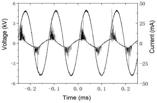
Figure 1.
The waveforms of applied voltage and discharge current recorded by an oscilloscope in He discharge.
Figure 2 shows the relationship between the concentration of CN− and treatment time for different discharge gases. The same trend of a monotonous decrease in CN− concentration with time is observed for all the gases. However, different discharge gases show highly different efficiency in the destruction of CN−. The cyanide destruction rates decrease in the order of He > O2 > N2. It is shown that the concentrations of CN− in the water decrease from 100 ppm to 32, 47, and 67 ppm for He, O2, and N2, respectively, after 1 h at a discharge voltage of 21.0 kV. Among the above three discharge gases, He plasma is the most efficient in the degradation of CN− in wastewater. Some kinds of active species such as high-energy electrons, H2O2,·OH radicals, O3, and OH radicals are formed in the plasma discharge of various gases, which are associated with the destruction of CN− in water [11,15,16]. Some of these active species, e.g., higher-energy electrons and radicals, are short-lived, and they can only react with CN− when the water sample flows through the discharge zone. H2O2 and O3 are the most stable oxidative species, which are stable enough to circulate with cyanide water in the plasma loop reactor, so they still can play an important role in oxidizing CN− outside the DBD zone. Due to its high efficiency in destruction of CN−, the following experiments were carried out with He plasma discharge only.
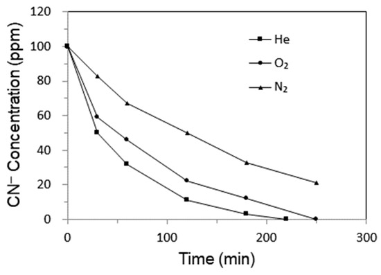
Figure 2.
The CN− concentration curve vs. treatment time for different discharge gases.
The effect of discharge voltage on cyanide degradation was studied at a He flow rate of 150 mL/min and cyanide circulating rate of 100 mL/min. It is shown in Figure 3 that the discharge voltage affected the rate of cyanide destruction significantly. After 60 min, the concentrations of CN− dropped to 20, 32, and 60 ppm at discharge voltages of 28.0, 21.0, and 12.0 kV, respectively. The CN− destruction rate was enhanced with the increase in discharge voltage. Higher discharge voltage may transfer more energy into the plasma zone between two electrodes, resulting in higher production rates of oxidative species in cyanide water. These oxidative species are active for in situ oxidation of CN−.
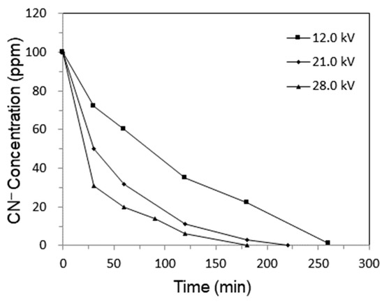
Figure 3.
The CN− concentration curve vs. He discharge voltage.
2.1.2. Effect of Water Temperature
It was observed experimentally that continuous circulation of cyanide water through the plasma discharge zone was indispensable for achieving effective cyanide degradation. In the absence of water circulation, the cyanide concentration was still as high as 96 ppm after 1 h of treatment, corresponding to only 4% CN− removal. This limited degradation was primarily attributed to the lack of liquid-phase contact within the He discharge zone, which was crucial for H2O2 generation, a key oxidant involved in cyanide destruction. In this DBD loop reactor, cyanide water was continuously circulated through the discharge zone as a thin falling film, thereby maximizing interfacial contact with the He plasma. This reactor configuration improved the interfacial transport of reactive species and energy from the plasma to the aqueous phase, thereby promoting the in situ formation of H2O2 and facilitating the direct degradation of CN− by other reactive species generated in the He plasma discharge.
The effect of water temperature on the degradation of CN− was investigated. As shown in Figure 4, the concentration of CN− in He DBD loop reactor decreased with temperature up to 60 °C and then started to increase with temperature. High temperature is favorable for the oxidation of CN−. However, in view of the H2O2 formed in He plasma discharge, which plays a very important role in oxidation of CN−, high temperature may cause the degradation of H2O2, thus affecting the efficiency of destruction of CN−.
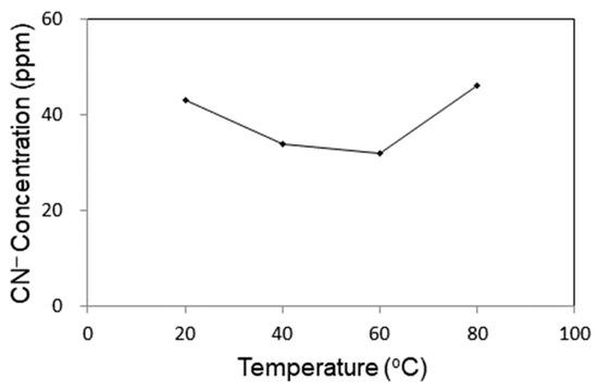
Figure 4.
Effect of temperature on the degradation of CN− in cyanide water.
2.1.3. Effect of Water pH
Under acidic conditions, CN− can be converted into volatile HCN which is highly toxic and should be avoided. Wastewater containing CN− should be kept under basic conditions, and the basicity was adjusted in the range 9.03–12.20 by HCl and NaOH to investigate the effect of pH on the degradation of CN−. As shown in Figure 5 the degradation rate at a pH of 9.03 was the fastest. To avoid the evolution of hydrogen cyanide, the cyanide water was set at a pH value of 10 in the experiments.
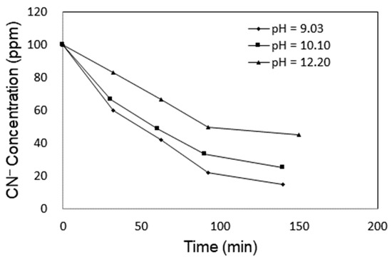
Figure 5.
Effect of pH on the degradation of CN− in cyanide water.
2.2. The Integration of CuNiAl LDH Catalysts and Plasma Discharge
It is shown in Figure 3 that DBD of He over the surface of a falling water film may degrade cyanide in water. However, it takes about 3 h for complete destruction of 100 ppm of cyanide anions in water. Cu2+ ions are efficient catalysts in the oxidation of cyanide in the presence of H2O2. The mechanism of cyanide oxidation by H2O2 in the presence of Cu2+ catalysts was proposed as follows [17]:
A Cu2+ ion is reduced to form the tricyanocuprate complex. Cyanogen is hydrolysed with disproportionation to cyanate and cyanide.
The oxidation of cyanide by H2O2 in alkaline aqueous solution is catalyzed by the tricyanocuprate complex.
Although effective, the use of a soluble copper catalyst brings new problems of elimination of downstream copper contaminant. Therefore, the use of heterogeneous catalysts is more appropriate in the treatment of wastewater. To enhance the degradation of cyanide ions, CuNiAl LDH catalysts were synthesized and employed for the oxidation of cyanide ions in wastewater using oxidizing species generated in situ in the plasma loop reactor. Figure 6 shows the X-ray diffraction (XRD) patterns of the as-synthesized CuNiAl-L, CuAl-L, and calcined CuNiAl-C samples. The patterns of the as-synthesized CuNiAl-L samples show the hydrotalcite structure as the only crystalline phase, exhibiting characteristic reflections at 2θ values of 12°, 23°, 35°, 39°, 47°, 61°, and 63°. On the contrary, CuAl-L consisted of mixed phases of CuO and hydrotalcite. The calcination of CuNiAl-L samples at 800 °C led to the thermal decomposition of hydrotalcite structures with the formation of the metal oxides NiO and CuO and spinel phases.
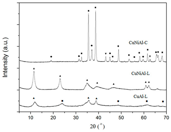
Figure 6.
The XRD patterns of the as-synthesized CuNiAl-L, CuAl-L LDHs, and calcined CuNiAl-C catalysts. Symbols indicate the presence of hydrotalcite (▲), CuO (■), NiO (▼), and spinel (●) phases.
Table 1 shows the composition and atomic molar ratio of Ni/Cu/Al and specific surface areas of the samples. The atomic molar ratio of divalent metal ions (M2+) to trivalent aluminum ions (Al3+) was consistently around 3.14:1. The M2+ ions either were composed of Cu2+ and Ni2+ with the molar ratio of Ni2+ to Cu2+ being 2.63:0.5 or consisted solely of Cu2+. It was observed that the composition of the samples and the calcination temperatures affected the surface area. The specific surface areas of CuNiAl-L, CuAl-L, and CuNiAl-C were 86, 49, and 39 m2/g, respectively. This indicates that the Brunauer–Emmett–Teller (BET) surface areas of the LDH catalysts decreased with the increase in the concentration of copper and calcination temperature.

Table 1.
Elemental composition and formula of the samples synthesized.
In each experiment, 0.1 g of catalyst was added into the reservoir containing 250 mL of wastewater to make the weight ratio of water to catalyst equal to 2500 to 1. It is observed in Figure 7 that the degradation of cyanide ions over these three catalysts was in the order of CuNiAl-L > CuAl-L > CuNiAl-C. It is well known that soluble copper salt is an active catalyst in accelerating the rate of oxidation of cyanide ions in wastewater. Although the CuNiAl-L catalyst contains fewer copper active centers than the CuAl-L catalyst, the higher oxidation rate over that of the CuNiAl-L catalyst suggests that nickel in CuNiAl-L may play an important role in the oxidation of cyanide ions. Both nickel and copper can form cyano-metal complexes with cyanide ions in aqueous solutions. It was reported that nickel formed a more stable cyano-metal complex than copper [18]. The formation constant logK of Cu(CN)42− and Ni(CN)42− is 23.1 and 30.2, respectively. The stronger affinity of nickel with cyanide ions may contribute to the higher catalytic activity of the CuNiAl-L catalyst.
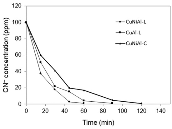
Figure 7.
Effect of CuNiAl-L and CuAl-L LDHs and the calcined CuNiAl-C catalysts on the destruction of CN− in the DBD loop reactor.
To investigate the physisorption of cyanide ions by CuNiAl-L and CuAl-L and the calcined CuNiAl-C catalysts., 0.1 g of catalyst was added into the cyanide water containing 100 ppm of CN− under vigorous stirring, and the concentration of cyanide ions was analyzed at different time intervals. As shown in Figure 8, the CuNiAl-L catalyst had a stronger affinity to the cyanide ions. After 1 h of adsorption equilibrium, the concentration of cyanide ions decreased from the initial 100 ppm to 72 ppm and 82 ppm with the CuNiAl-L and CuAl-L catalysts, respectively. This phenomenon is likely attributable to both the higher surface area of the former catalyst and the stronger affinity between nickel and cyanide ions. The concentration of cyanide ions observed for the calcined CuNiAl-C at adsorption equilibrium was 75 ppm, higher than that with the CuNiAl-L catalyst. This may possibly be due to the crystal phase transformation coupled with the loss of the specific surface area after calcination of the hydrotalcite phase.
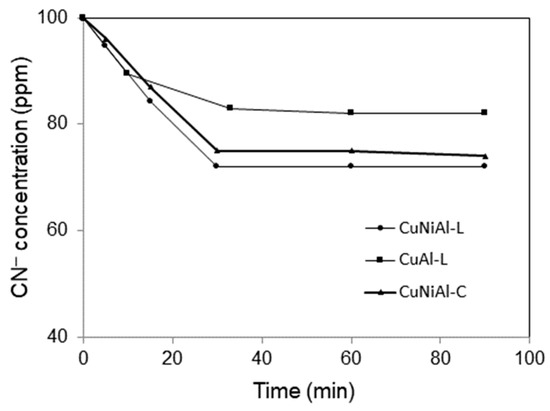
Figure 8.
The physisorption of cyanide ions by CuNiAl-L, CuAl-L LDHs, and the calcined CuNiAl-C catalysts.
The combination of the CuNiAl-L catalyst and He plasma discharge is an efficient means to destruct cyanide ions in water by oxidizing them to cyanate in a plasma–catalyst loop reactor. As shown in Figure 7, the observed rate of degradation of cyanide in water obeys first-order kinetics with respect to cyanide concentration in the form of
Integrating Equation (2), we obtain
Here, = 100 ppm represents the initial CN− concentration. Based on experimental data of vs. t in Figure 7, the rate constant, k, can be easily estimated to be 0.07 min−1.
3. Materials and Methods
3.1. Materials and Catalyst Preparation
Copper nitrate trihydrate (Cu(NO3)2∙3H2O), aluminum nitrate nonahydrate (Al(NO3)3∙9H2O), nickel nitrate hexahydrate (Ni(NO3)2∙6H2O), sodium hydroxide (NaOH), sodium carbonate (Na2CO3), hydrogen peroxide (H2O2, 30.0 wt%), and silver nitrate (AgNO3) were all purchased from Sinopharm chemical regent Co., Ltd., Shanghai, China. All the chemicals were of analytical grade.
The CuNiAl LDH catalysts were synthesized by the co-precipitation method. One metal nitrate solution comprising a mixture of nitrates of Cu2+, Ni2+, and Al3+ tuned with different ratios and another precipitant solution comprising a mixture of NaOH and Na2CO3 were added concurrently through two feed lines of a peristaltic pump into a three-neck reaction flask with vigorous stirring. During the precipitation process the mixture’s pH was maintained at 9–10 and temperature was kept at 50 °C using a water bath. After the addition of solutions was completed, the mixture was aged at 50 °C for 12 h with vigorous stirring. Finally the precipitate was filtered, washed using de-ionized water until it was nitrate-free, and then dried at 110 °C for 6 h. The dried samples were either used directly as catalysts (denoted by CuNiAl-L) or subjected to calcination at 1013 K for 2 h prior to water treatment (denoted by CuNiAl-C).
3.2. Plasma–Catalyst Loop Reactor Setup
The DBD plasma–catalyst loop reactor setup shown in Figure 9 comprised a quartz tube and a concentric stainless tube. The quartz tube had dimensions of 22 mm o.d. × 18 mm i.d. × 250 mm length. Wrapped on the external surface of the quartz tube was the stainless steel mesh, which was used as a high-voltage electrode. Stainless steel of the dimensions 8.0 mm o.d. × 3.0 mm i.d. was mounted inside the quartz tube and served as the ground electrode. Gas feed (He, N2 and O2), controlled by mass flow controllers, was introduced through the opening on the top of the quartz tube. The water sample was introduced into the inner pore of the stainless steel tube from the bottom by a peristaltic pump. The water sample left from the top of the stainless tube and flowed down along the external surface of stainless steel tube as a thin falling film. The gas and water sample left the reactor from the bottom opening of the quartz tube, passed through a tube and shell heat exchanger, and were collected in the reservoir. The gas was then vented from the top opening of the reservoir, and the cyanide water was pumped using the peristaltic pump to circulate it inside the plasma loop reactor. The DBD plasma discharge was generated in the circle slit between the quartz tube and stainless steel tube.
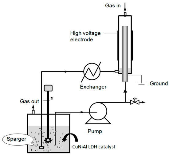
Figure 9.
Experimental setup of plasma–catalyst loop reactor.
3.3. Material Characterization
Cyanide solution was prepared by dissolving sodium cyanide with deionized water, and the pH of the solution was adjusted to a specific value by HCl and NaOH solutions. In each experiment, a 250 mL water sample (100 ppm CN−) was used. Cyanide concentration in the water was titrated using a standard silver nitrate solution [19]. The DBD was generated by the power supply (CTP-2000, Corona Lab, Nanjing, China). The oscilloscope (TDS1012B-SC, Tektronix, Beaverton, OR, USA) was used to measure the discharge power by calculating the area of the voltage/charge Lissajous figures.
The structure properties of the samples were investigated byXRD (X’PertPro MPD, PANalytical, Almelo, The Netherlands) using a CuKa monochromatized radiation source and a Ni filter in the range of 2θ = 5–75o. The content of crystalline phases was evaluated using the relative intensity of the strongest diffraction peaks of standard pure materials. The surface areas (BET) were determined by nitrogen adsorption at –196 °C using an automated gas adsorption analyzer (ASAP2020-M, Micromeritics, Norcross, GA, USA). The pore size distribution was calculated from the adsorption branch of the isotherm by the Barrett, Joyner, and Halenda (BJH) method. The elemental composition of catalysts was measured using an inductively coupled plasma optical emission spectrometer (ICP-OES, Optima 7000 DV, PerkinElmer Inc., Waltham, MA, USA).
4. Conclusions
In this work, Cu-containing LDHs were successfully employed in the oxidation of cyanide ions in water in a DBD loop reactor without addition of oxidants. He gas was chosen as the discharge gas because compared to N2 and O2 it gave the highest CN− destruction rate. Circulating cyanide water through the He discharge zone in the form of a falling thin film enhanced CN− degradation. Depending on discharge voltage, it took 180 to 300 min for complete degradation of 100 ppm of CN− in water by He DBD alone. Cu-containing LDH catalysts were synthesized and employed as catalysts in the reactor. Among them the CuNiAl-L catalyst showed superior CN− oxidation activity over its counterpart CuNiAl-C and CuAl-L, probably due to its hydrotalcite structure and the strong affinity of nickel with cyanide ions. The treatment time required for complete removal of 100 ppm of CN− with CuNiAl-L was shortened to about 60 min. The integration of Cu-containing LDH catalysts and He DBD in this loop reactor eliminated the supply of oxidant and downstream copper ion removal step and thus is very efficient for the degradation of cyanide water.
Funding
The support of this work by the Fundamental Research Funds for the Central Universi-ties (Grant No. 24720094028) is gratefully acknowledged.
Data Availability Statement
The data will be made available upon request.
Conflicts of Interest
The author declares no conflicts of interest.
References
- Akcil, A. Destruction of cyanide in gold mill effluents: Biological versus chemical treatments. Biotechnol. Adv. 2003, 21, 501–511. [Google Scholar] [CrossRef] [PubMed]
- Teixeira, L.A.C.; Andia, J.P.M.; Yokoyama, L.; Araujo, F.V.; Sarmiento, C.M. Oxidation of cyanide in effluents by Caro’s Acid. Miner. Eng. 2013, 45, 81–87. [Google Scholar] [CrossRef]
- Lee, T.Y.; Kwon, Y.S.; Kim, D.S. Oxidative treatment of cyanide in wastewater using hydrogen peroxide and homogeneous catalyst. J. Environ Sci Health 2004, 39, 787–801. [Google Scholar] [CrossRef] [PubMed]
- Pak, D.; Chang, W. Oxidation of aqueous cyanide solution using hydrogen peroxide in the presence of heterogeneous catalyst. Environ. Technol. 1997, 18, 557–561. [Google Scholar] [CrossRef]
- Kitis, M.; Akcil, A.; Karakaya, E.; Yigit, N.O. Destruction of cyanide by hydrogen peroxide in tailings slurriesfrom low bearing sulphidic gold ores. Miner. Eng. 2005, 18, 352–362. [Google Scholar] [CrossRef]
- Yeddou, A.R.; Chergui, S.; Chergui, A.; Halet, F.; Hamza, A.; Nadjemi, B.; Ould-Dris, A.; Belkouch, J. Removal of cyanide in aqueous solution by oxidation with hydrogen peroxide in presence of copper-impregnated activated carbon. Miner. Eng. 2011, 24, 788–793. [Google Scholar] [CrossRef]
- Wang, H.; Xiang, X.; Feng, L.; Evans, D.G.; Duan, X. Investigation of the structure and surface characteristics of Cu-Ni-M(III) mixed oxides (M = Al, Cr and In) prepared from layered double hydroxide precursors. Appl. Surf. Sci. 2009, 255, 6945–6952. [Google Scholar] [CrossRef]
- Dubey, A.; Rives, V.; Kannan, S. Catalytic hydroxylation of phenol over ternary hydrotalcites containing Cu, Ni and Al. J. Mol. Catal. A-Chem. 2002, 181, 151–160. [Google Scholar] [CrossRef]
- Morinaga, K. The reaction of hydrogen and oxygen through a silent electric discharge. I. The formation of hydrogen peroxide. Bull. Chem. Soc. Jpn. 1962, 35, 345–348. [Google Scholar] [CrossRef]
- Morinaga, K. The reaction of hydrogen and oxygen through a silent electric discharge. II. The effect of packings on a peroxide formation. Bull. Chem. Soc. Jpn. 1962, 35, 625–626. [Google Scholar] [CrossRef]
- Zhao, J.L.; Zhou, J.C.; Guo, H.C.; Wang, X.S.; Gong, W.M. Scale-up synthesis of hydrogen peroxide from H2/O2 with parallel DBD tubes. Plasma Sci. Technol. 2009, 11, 181–186. [Google Scholar]
- Banaschik, R.; Lukes, P.; Jablonowski, H.; Hammer, M.U.; Weltmann, K.D.; Kolb, J.F. Potential of pulsed corona discharges generated in water for the degradation of persistent pharmaceutical residues. Water Res. 2015, 84, 127–135. [Google Scholar] [CrossRef] [PubMed]
- Valsero, M.H.; Molina, R.; Schikora, H.; Müller, M.; Bayona, J.M. Removal of cyanide from water by means of plasma discharge technology. Water Res. 2013, 47, 1701–1707. [Google Scholar] [CrossRef] [PubMed]
- Fortin, L.; Kasireddy, V.K.; Soucy, G.; Bernier, J.L. Novel reactor for cyanide solution treatment. Can. J. Chem. Eng. 2010, 78, 643–649. [Google Scholar] [CrossRef]
- Simek, M.; Clupek, M. Efficiency of ozone production by pulsed positive corona discharge in synthetic air. J. Phys. D Appl. Phys. 2002, 35, 1171–1175. [Google Scholar] [CrossRef]
- Wang, B. A novel dielectric-barrier discharge loop reactor for cyanide water treatment. Plasma Chem. Plasma Process. 2017, 37, 1121–1131. [Google Scholar] [CrossRef]
- Beattie, J.K. and Polyblank, G.A. Copper-catalysed oxidation of cyanide by peroxide in alkaline aqueous solution. Aus. J. Chem. 1995, 48, 861–868. [Google Scholar] [CrossRef]
- Rees, K.L. and Deventer, J.S.J. The role of metal-cyanide species in leaching gold from a copper concentrate. Miner. Eng. 1999, 12, 877–892. [Google Scholar] [CrossRef]
- Baird, R.; Bridgewater, L. American Public Health Association; American Water Works Association; Water Environment Federation. In Standard Methods for the Examination of Water and Wastewater, 23rd ed.; American Public Health Association: Washington, DC, USA, 2017. [Google Scholar]
Disclaimer/Publisher’s Note: The statements, opinions and data contained in all publications are solely those of the individual author(s) and contributor(s) and not of MDPI and/or the editor(s). MDPI and/or the editor(s) disclaim responsibility for any injury to people or property resulting from any ideas, methods, instructions or products referred to in the content. |
© 2025 by the author. Licensee MDPI, Basel, Switzerland. This article is an open access article distributed under the terms and conditions of the Creative Commons Attribution (CC BY) license (https://creativecommons.org/licenses/by/4.0/).