Article

Electrodeposition of Bismuth Dendrites on Oxide-Derived Copper Foam Enhancing Electrochemical CO2 Reduction to Formate

1
School of Light Industry and Engineering, South China University of Technology, Guangzhou 510640, China
2
State Key Laboratory of NBC Protection for Civilian, Beijing 100025, China
*
Authors to whom correspondence should be addressed.
Catalysts 2025, 15(1), 52; https://doi.org/10.3390/catal15010052
Submission received: 22 November 2024 / Revised: 29 December 2024 / Accepted: 1 January 2025 / Published: 8 January 2025

Abstract

:
The electrochemical CO2 reduction reaction (CO2RR) to formate offers a promising pathway to mitigate the energy crisis and realize carbon neutrality. Bismuth (Bi), as a metal catalyst for the CO2RR, is considered to have great potential in producing formate, yet hindered in low current density and selectivity. Herein, we constructed an oxide-derived copper foam substrate (OD-Cu) to improve the electrocatalytic properties of Bi dendrites loaded on its surface. Bi electrodeposited on the OD-Cu (Bi/OD-Cu) grows as pinecone-like dendrites, exhibiting a high formate faradaic efficiency (FEformate) of 97.2% and a formate partial current density of ~24 mA·cm−2 at −0.97 V vs. RHE (reversible hydrogen electrode) in an H-cell. Notably, the Bi/OD-Cu electrode demonstrates an FEformate of 95.8% at −0.97 V vs. RHE and a total current density close to 90 mA·cm−2 at −1.17 V vs. RHE in a neutral flow cell. The experimental studies reveal that the remarkable CO2RR performance of the Bi/OD-Cu results from the electron transfer from Cu to Bi, which optimizes adsorption of the CO2•− and boosts reaction kinetics. This study emphasizes the crucial role of substrate engineering strategies in enhancing catalytic activity and shows the possibility for a porous metal electrode in advancing the industrialization of formate production.

Graphical Abstract

1. Introduction

The continuous rise in global industrialization has resulted in an annual increase in carbon dioxide emissions [1]. The consequent global warming has spurred the search for sustainable methods to reduce carbon emissions [2,3,4]. Carbon dioxide (CO2), being a plentiful and inexpensive carbon source, can be transformed into valuable hydrocarbon compounds through renewable energy-driven electrochemical techniques under mild conditions [5,6]. This approach not only enhances carbon cycling but also facilitates energy redistribution. Market and technological analyses indicate that formic acid and formate as fuels and hydrogen storage mediums have vast market potential [7]. However, the complexity of the proton-coupled electron transfer mechanisms in CO2 reduction reactions, which result in various products [8,9], constrains the activity and selectivity of CO2 reduction electrocatalysts. CO2 reduction also faces the kinetically advantageous competitive hydrogen evolution reaction (HER) [10]. Therefore, the development of catalysts with high catalytic activity and selectivity remains a critical challenge in the research on CO2 conversion to formic acid or formate.
Researchers have invested significant efforts in developing advanced electrocatalysts with p-block metals (Sn [11], Bi [12], In [13], Pb [14]), and their oxides are reported to exhibit excellent catalytic activity and selectivity for CO2 reduction to formate. Among these, Bi-based catalysts are considered to be the most promising catalysts for practical application due to low cost and environmental friendliness. However, Bi monometallic catalysts have limitations, such as low current density and a narrow potential window for high Faradaic efficiency, severely hindering their large-scale application. Various strategies have been proposed to improve these catalysts, including morphological control [15,16], element doping [17,18], interface engineering [19,20], and defect engineering [21,22], which can achieve superior CO2 reduction reaction performance. Recent studies suggest that copper foam offers the potential for achieving industrial-level current densities within a confined electrode area because of its excellent conductivity. Further optimization of copper foam may provide a cost-effective solution [23]. Liu et al. [24] reported a nanoscale tin–oxide-modified copper–oxide foam hybridized gas-diffusion electrode causing an increase in the thickness of a triple-phase interface. Using the resultant electrode, the partial current density of formate (Jformate) is increased to −1152 mA·cm−2 at −1.2 V (vs. RHE) in 1.0 M KOH, and the FEformate reaches about 99% at −0.6 V (vs. RHE). The inherent porous network structure of the substrate not only offers ideal sites for catalyst growth but also enhances gas and liquid transport. Moreover, surface modification of copper foam substrates combined with simple electroplating processes can tailor catalysts to have higher activity and efficiency and longer lifespans [25,26]. Ma et al. [27] used Cu nanowires on the surface of Cu foam as a template to obtain Bi nanowires. The Bi nanowire catalyst was found to be a highly active electrocatalyst for CO2 reduction to formate, achieving a Faradaic efficiency for formate above 90% within a wide potential window of −0.68~−1.08 V (vs. RHE). Although many studies have shown that derivatized copper foam substrates can enhance the CO2RR performance of catalytic electrodes, there are few reports on the direct application of porous metal electrodes to a flow cell.
Inspired by the above, our group designs Bi pinecone-like dendrite catalysts supported on an oxide-derived copper foam substrate (denoted as Bi/OD-Cu) by the electrodeposition method. Firstly, Cu(OH)2 nanoneedles were prepared on the raw foam copper (denoted as Cu(OH)2/Cu foam) via electrochemical oxidation. Secondly, they were chemically reduced to Cu/CuO nanoparticles, resulting in a rough-surfaced oxide-derived copper foam substrate (denoted as OD-Cu). Finally, Bi catalysts were deposited onto the oxide-derived Cu (denoted as Bi/OD-Cu) via electroplating, enabling efficient CO2 reduction with outstanding selectivity over a broad potential range. In the H-cell, within a voltage range of −0.87 V to −1.17 V (vs. RHE), the catalytic electrode achieved a significant Faradaic efficiency of formate over 92%, with an impressive FEformate of 97.2% and a partial current density of 24.2 mA·cm−2 at −0.97 V (vs. RHE). The experimental studies indicate that the exceptional performance of the Bi catalysts is attributed to the enhanced electron supply from the oxide-derived copper foam to its active sites, optimizing the electronic cloud distribution of the Bi active sites. Notably, the Bi/OD-Cu electrode achieved an FEformate > 90% at −1.07 V (vs. RHE), with a partial current density reaching approximately 55 mA·cm−2 when it was applied directly to a neutral electrolyte flow cell. This work provides experimental and data support for a deeper understanding of the synergistic effects between copper foam substrates and electrocatalysts, expanding the feasibility of porous metal electrodes in flow cell applications.

2. Results and Discussion

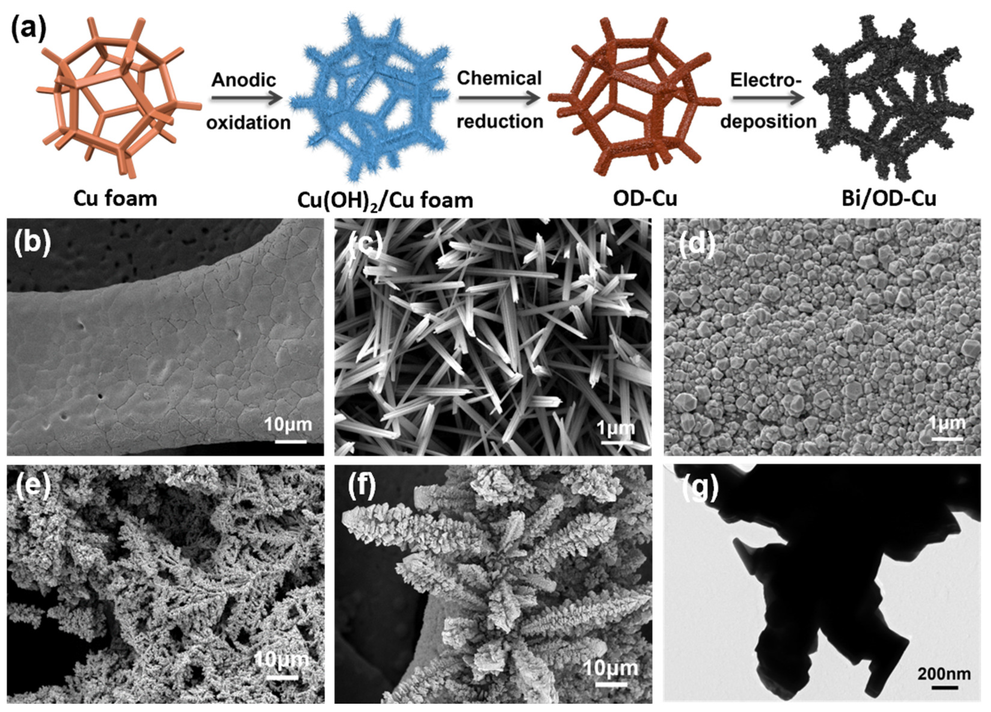
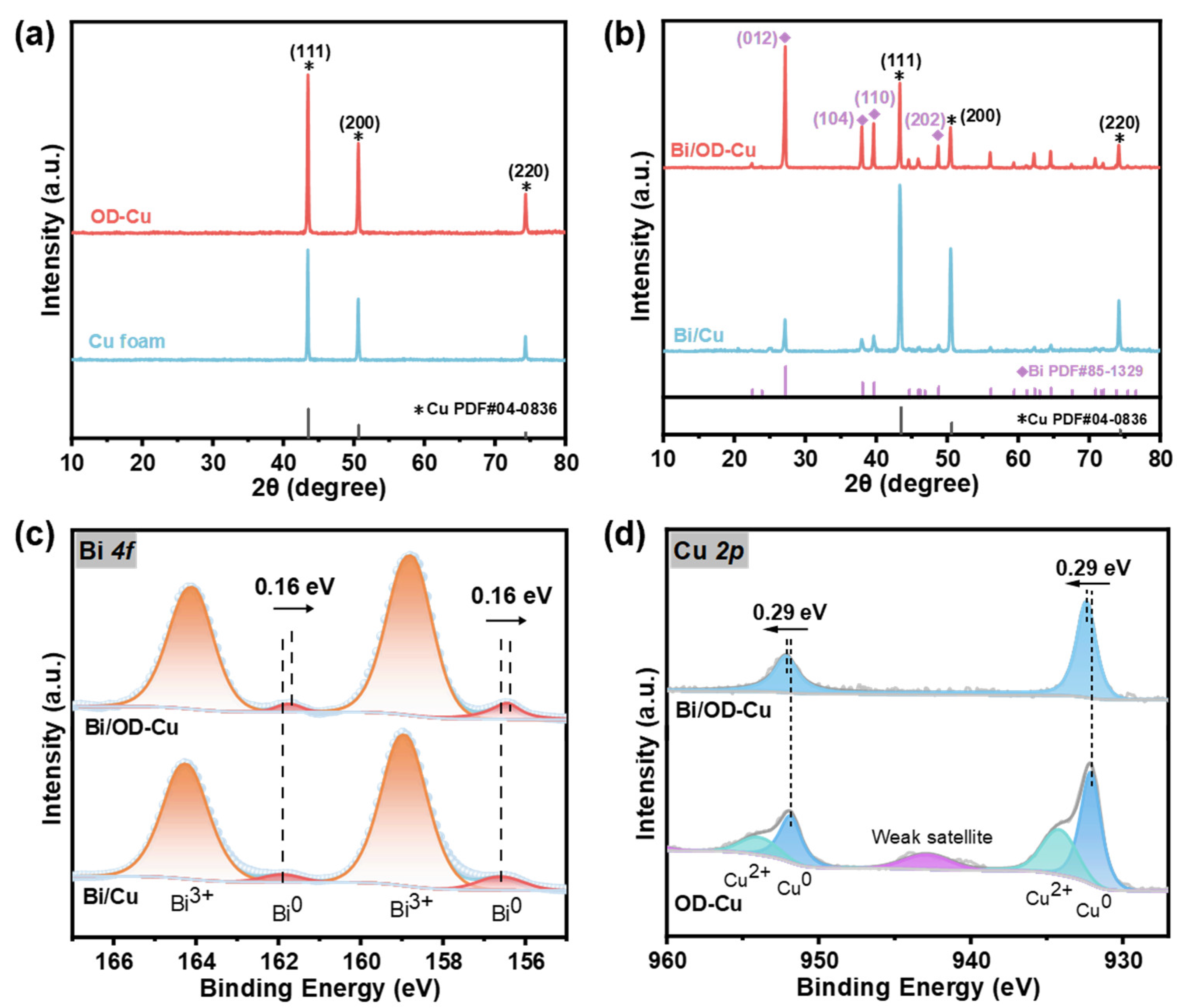
2.1. Synthesis and Characterizations of the Bi/OD-Cu

As briefly illustrated in Figure 1a, the Bi/OD-Cu electrode was fabricated by electrodeposition via three steps. First, Cu(OH)2 nanoneedles were grown on the surface of the copper foam via a modified electrochemical oxidation method [28]. Subsequently, the Cu(OH)2/Cu foam was reduced to the OD-Cu by immersing in an ascorbic acid solution. Thus, the OD-Cu was used as the substrate for loading bismuth by electroreduction. Figure 1b–g show the SEM morphology of the Cu foam, Cu(OH)2 nanoneedles, OD-Cu, and Bi/OD-Cu. As observed from Figure 1b, the surface of the untreated Cu foam is flat and has lots of small cracks. And the Cu(OH)2 nanoneedles on the surface of the Cu foam after electro-oxidation (Figure 1c) had a diameter of about 200 nm. The needle-like structure was turned into nanoparticles (Figure 1d) after being soaked in ascorbic acid. And it formed a coarse surface, which was conducive to the deposition and growth of Bi3+. As shown in Figure 1f, the Bi/OD-Cu revealed a complete pinecone-like dendrite structure, while the Bi/Cu showed a structure like pine leaves (Figure 1e), which grew non-uniformly on the substrate (Figure S1). What is more, with an increasing deposition current density, the pinecone-like dendrites gradually developed into clusters, confirming that 4 mA·cm−2 was appropriate for even growth and distribution of Bi dendrites (Figure S1b–d). Observation of the Bi/OD-Cu from a transmission electron microscope (TEM) further demonstrated the single nanostructure of the catalyst (Figure 1g). Unfortunately, Bi is so intolerant of irradiation that we could hardly analyze the lattice fringes in depth. The energy-dispersive X-ray spectroscopy (EDS) mapping in Figure S2 further confirmed the distribution of Bi on the surface of the OD-Cu support.
The crystal structure of the substrate was measured by X-ray diffraction (XRD), where only the diffraction peaks attributed to metallic Cu (JCPDS No. 04-0836) were found (Figure 2a). In addition, a series of diffraction peaks appeared at 27.2°, 38.0°, 39.6°, and 48.7°, corresponding to the Bi (012), (104), (110), and (202) crystal planes (JCPDS No. 85-1329, Figure 2b) after loading bismuth. It can be obviously seen that the peaks of the Bi/OD-Cu are more intensive than those of Cu/Bi, which might imply better catalytic property to formate [29,30,31]. As can be seen from the Bi (012) crystal surface (Figure S3), with the increase in deposition current density, the diffraction intensity of the Bi active crystal surfaces is first enhanced and then decreases, which is consistent with the change in the catalyst microscopic morphology, predicting the change pattern of the corresponding catalytic activity of the Bi dendrites.
Furthermore, X-ray photoelectron spectroscopy (XPS) was conducted to ascertain the surface elemental composition and electronic state of the Bi/OD-Cu. The complete XPS survey spectrum of the Bi/OD-Cu sample (Figure S4) clearly showed the characteristic peaks for Cu 2p, O 1s, and Bi 4f. As shown in the spectrum of Bi 4f (Figure 2c), one set of peaks, located at 156.44 and 161.75 eV, was assigned to Bi0 metal [32], while another set, at 158.77 and 164.08 eV, was attributed to the Bi3+ species that results from inevitable surface oxidation of the samples during the transfer process [33,34]. The high-resolution XPS spectrum of Cu 2p on the OD-Cu displayed four characteristic peaks (Figure 2d), with the peaks at 932.11 eV and 951.86 eV associated with Cu0,1+ [35] and the peaks at 934.16 eV and 953.91 eV associated with Cu2+ [36]. However, the high-resolution XPS spectrum of Cu 2p on the Bi/OD-Cu showed characteristic peaks of Cu0 at 932.4eV and 952.15 eV without any detectable peaks related to Cu2+. Cu2+ is supposed to be reduced during electrodeposition, and the uniformly coated Bi dendrites on the surface prevented the internal copper from oxidizing during the transfer process by preventing contact with air [30]. In contrast to Bi/Cu, the XPS peaks of Bi0 in the Bi/OD-Cu slightly shifted toward a lower binding energy (Figure 2c and Figure S4c), whereas the binding energy of Cu0 2p displayed a positive shift relative to that of the OD-Cu counterpart. This phenomenon confirms the existence of electron transfer from Cu to Bi and, thus, results in electron-rich Bi dendrites favoring CO2 adsorption [37,38]. Additionally, in the O 1s spectrum (Figure S4d), the fitted peaks at 529.47 eV and 531.22 eV are probably associated with the Bi–O lattice bonds and adsorbed oxygen [39,40,41]. For the CO2RR, the formation of Bi–O effectively modulates the adsorption conformation of the reaction intermediate and promotes the formation of *OCHO (asterisk denotes as adsorption site) [42].

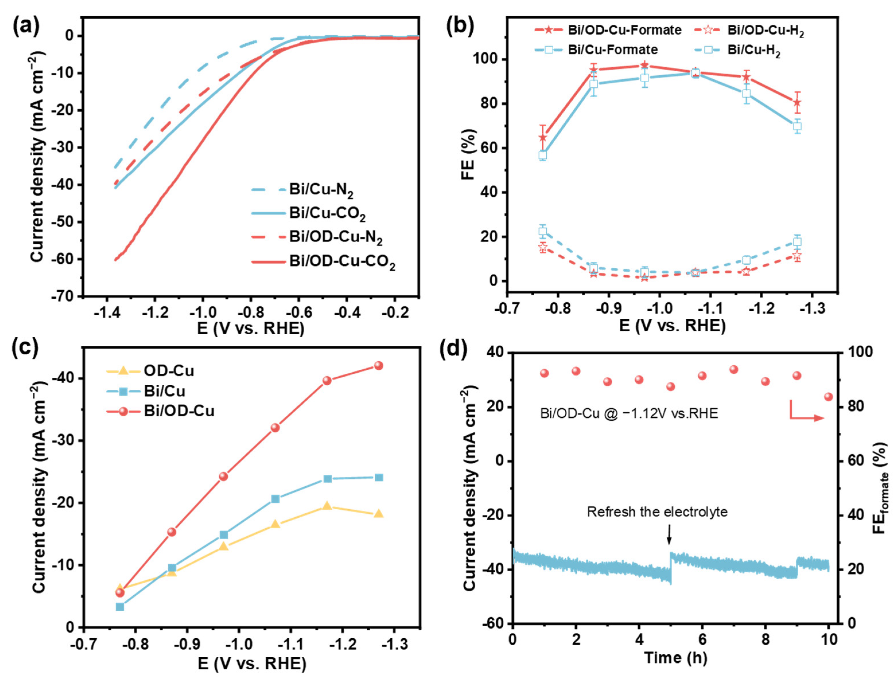
2.2. Electrochemical CO2RR Performance in an H-Cell

The electrochemical CO2 reduction performance of the Bi/OD-Cu was evaluated in an H-cell. The linear sweep voltammetry (LSV) curves were first carried out under a N2-saturated 0.5 M KHCO3 solution (Figure 3a). It suggests that the occurrence of the CO2RR is easier than that of HER on Bi/Cu and the Bi/OD-Cu. Comparing with the Bi/Cu catalyst, the Bi/OD-Cu shows significantly enhanced current density and a more positive overpotential during the CO2RR. This indicates that the Bi/OD-Cu has a superior electrocatalytic property for the CO2RR. Although the OD-Cu support achieved a more sloping LSV curve (Figure S5), this did not indicate that it had better catalytic activity for the target products. To determine the CO2RR selectivity of the Bi/OD-Cu, Bi/Cu, and the OD-Cu, the liquid and gaseous products were detected and quantified by gas chromatography (GC) and ion chromatography (IC). The FEformate of the Bi/OD-Cu clearly shows volcanic trends from −0.87 to −1.17 V (vs. RHE) (Figure 3b). They are over 92% in a wide range of potentials, and the highest FEformate reached 97.2% at −0.97 V (vs. RHE). In contrast, the highest FEformate of the OD-Cu was 39.8% (Figure S5b), which indicates that the Bi/OD-Cu has excellent selectivity. Additionally, the Jformate of different electrodes was tested at various potentials to catalytic activity (Figure 3c). The Bi/OD-Cu exhibited a qualitative leap at the applied potential range. Impressively, the as-prepared Bi/OD-Cu displays a more exceptional performance for fomate than the Bi/Cu electrode, with both high Jformate (39.7 mA·cm−2) and FEformate (92.1%) at −1.17 V (vs. RHE).
In addition, the effect of the Bi/OD-Cu electrodeposition current density on the FEformate was studied (Figure S6). The FEformate reached the maximum when the electrode was prepared at 4 mA·cm−2. The suitable exposure of crystal planes and proper electron donation of the underlying OD-Cu nanoparticles to the Bi dendrites give the outstanding CO2RR performance. In addition, a long-time stability test was conducted at −1.12 V (vs. RHE). The Bi/OD-Cu electrode preserved great stability over 10 h (Figure 3d), with the yield of formate linear to the electrolysis time (Figure S7), with an average yield rate of 0.65 mmol·cm−2·h−1. The current density and FEformate (91% in average) had slight fluctuations as the concentration of formate in the electrolyte increased, which is a quite normal phenomenon in an H-cell [43,44,45]. After the long-term reaction test, several parts of the nano-dendrites transformed into nano-crumples (Figure S8), and the XPS peaks of Bi0 shifted positively, accompanied by diminishing intensity (Figure S9). The XRD spectra (Figure S1) show no significant changes in the crystal structure after the reaction. The morphological reconstruction and metal oxidation might trigger the degradation of electrocatalytic performance. In comparison to recently reported Bi-based catalysts (Table S2), our Bi/OD-Cu electrode achieves higher Jformate than most other reported electrodes under identical potential conditions while maintaining excellent selectivity for formate.

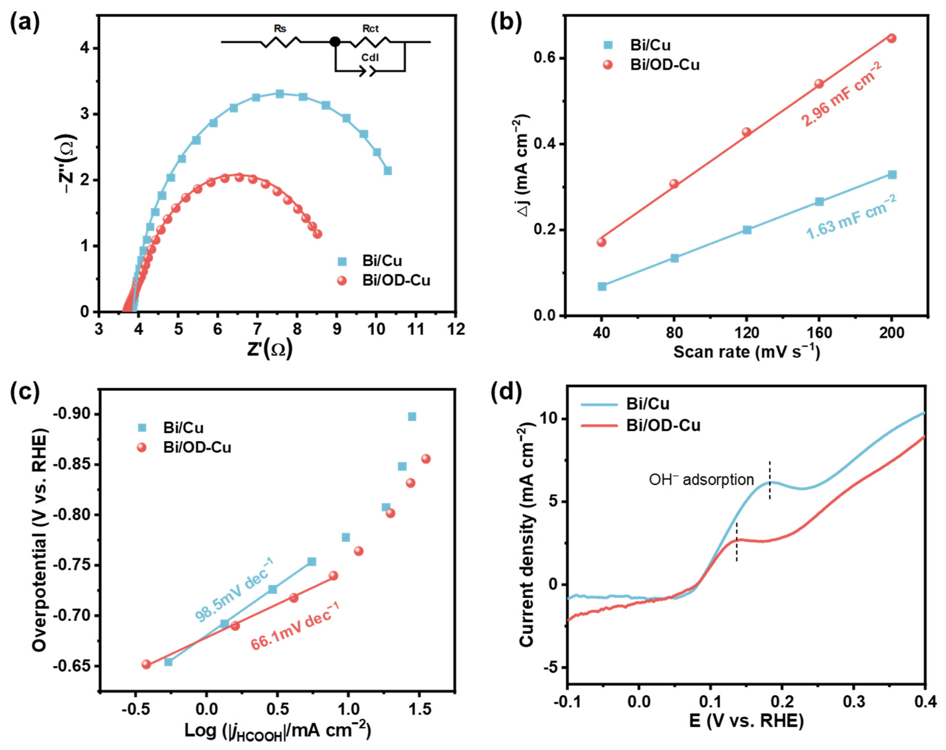
2.3. Mechanism Study of CO2 Reduction

In order to figure out the superior electrocatalytic performance of the Bi/OD-Cu catalyst, electrochemical impedance spectroscopy (EIS) was first performed on the different electrodes to investigate the charge transfer resistance (Rct). The Nyquist plots of the two electrodes were fitted by the equivalent circuit. Generally speaking, the smaller semicircle diameter in the EIS correlates with the lower Rct. Figure 4a shows that the Bi/OD-Cu possesses the lower charge transfer resistance (Rct = 5.20 Ω, Table S1), indicating a much faster charge transfer at the interface between electrode and electrolyte [46]. In addition, the electrochemically active surface area (ECSA) reflects the number of intrinsic active sites of the Bi/OD-Cu and Bi/Cu electrodes, and ECSA can be characterized by double-layer capacitance (Cdl) [47]. The individual cyclic voltametric curves (Figure S1) were tested to obtain the Cdl of the two electrodes (Figure 4b). It can be seen that the Bi/OD-Cu has larger Cdl than Bi/Cu. The higher activity of the Bi/OD-Cu is owing to the perfect growth of the dendrite structure.
+ C O 2 ( a d s ) + e C O 2 ( a d s )
C O 2 a d s + H C O 3 O C H O + C O 3 2
O C H O + e + H + + H C O O H
To gain an in-depth study into the kinetic insight of the CO2RR, Tafel slope was used to analyze the rate-determining step (RDS) [48]. Formulas (1)–(3) provide potential mechanisms for the CO2RR process on eletrocatalytic agents (* denotes the active surface site) [2,49]. In general, CO2 reduction typically initiates with the transfer of the first electron, forming the *CO2•− intermediate. This is followed by the protonation of the carbon atom, leading to the formation of the *OCHO species. Subsequently, proton transfer from HCO3 triggers the second electron transfer from the electrode, culminating in the production of formic acid. As shown in Figure 4c, the Tafel slope of the Bi/Cu electrode is 98.5 mV·dec−1, whereas the Tafel slope of the Bi/OD-Cu electrode is 66.1 mV·dec−1, illustrating faster reaction kinetics on the Bi/OD-Cu dendrite structure. Previous research has shown that the theoretical Tafel slope of the proton transport step is 59 mV·dec−1 [50]. Consequently, the activation of CO2 on the Bi/OD-Cu is easier, and its RDS could probably be proton transport (Equation (5)). The binding intensity of the CO2•− intermediate on the two samples (Figure 4d) was determined by using OH adsorption as a surrogate for the CO2•− intermediate [51]. Previous studies have shown that the binding intensity of the CO2•− intermediate increases at more negative potentials [52,53]. The Bi/OD-Cu possessed the highest adsorption affinity of the CO2•− intermediate, thereby efficiently stabilizing it.
Ex situ Raman spectroscopy and in situ electrochemical Raman spectroscopy were further performed to monitor the Bi/OD-Cu catalyst evolution and reaction intermediates during the CO2RR process. The peaks located at 123 cm−1 and 311 cm−1 were associated with the Bi–O stretching vibration of β-Bi2O3 (Figure S12) [54]. On scanning the applied potential from −0.5 V to −1.1V (vs. RHE) over the Bi/OD-Cu catalyst, these two peaks disappear, accompanied by observation of the Eg (53 cm−1) and A1g (77 cm−1) modes of Bi–Bi bonds (Figure S13) [55]. This suggests that bismuth oxide was reduced during CV activation. Concurrently, the vibrational fingerprints of C–H stretching of the *OCHO intermediate (2850 cm−1) are also observed for both the Bi/Cu (Figure 5a) and Bi/OD-Cu (Figure 5b) [56,57]. Intriguingly, for the Bi/OD-Cu electrocatalyst, the vibrational peak of the (2850 cm−1) intermediates appeared at a much lower applied potential (−0.5 V vs. RHE) than those on Bi/Cu (−0.7 V vs. RHE), confirming that the electron-abundant Bi in the Bi/OD-Cu significantly promotes the activation of CO2 molecules and facilitates the appearance of *OCHO intermediates. As illustrated in Figure 5c, the Bi/OD-Cu can facilitate the CO2 activation and promote the reaction kinetics. And the excellent CO2•− adsorption ability of the catalysts can contribute to the local CO2•− enrichment and, thus, suppress the competing side reactions. Moreover, the resultant electron-rich properties of the Bi atom can further promote the conversion of CO2•− to *OCHO. At the end, the *OCHO intermediates induce electrons to generate formate and desorb from the active site surface.

2.4. Electrochemical CO2RR Performance in the Flow Cell

To mitigate the effect of product accumulation in the electrolyte on Faraday efficiency and demonstrate the feasibility of porous metal catalytic electrodes for large-scale reactor applications, a commercially available flow cell apparatus (Figure 6a and Figure S14) was applied to the CO2RR experiment. It is noteworthy that the as-prepared electrode was directly assembled in the electrolyzer without hydrophobic treatment or using gas diffusion layers. From the polarization curves in Figure 6b, the total current density of the Bi/OD-Cu electrode in the flow cell reached approximately 90 mA·cm−2 at −1.17 V (vs. RHE), about two times that of the H-cell (~45 mA·cm−2). For one thing, the serpentine flow channel design of the flow cell as well as the inlet method, which shortens the diffusion distance of carbon dioxide, facilitate the formation of the three-phase interface and further enhance the reactant mass transfer efficiency [58,59]. For another, the distance between the cathode and anode in the flow cell is considerably shorter than in the H-cell, resulting in a decrease in the reactor’s internal ohmic resistance. As shown in Figure 6c, the FEformate of the Bi/OD-Cu was maintained over 90% from −0.87 V to −1.07 V (vs. RHE) and reached a maximum value of ~95.8% at −0.97 V (vs. RHE). Except for the narrowing of the potential window, the tendency of FEformate with the potential in the flow cell is similar to that in the H-cell. Furthermore, we calculated the yield rate of formate at different potentials in the H-cell and the flow cell, respectively (Figure S15). In the potential interval from −0.77 V to −1.17 V (vs. RHE), the rate of formate production accelerates with increasing potentials. At −1.17 V (vs. RHE), the yield rate reaches 1.90 mmol·cm−2·h−1 (flow cell) and 0.70 mmol·cm−2·h−1 (H-cell), which exceed some of the Bi-based catalysts reported so far (Table S3).
Furthermore, we chose the voltage of −1.02 V (vs. RHE) for the long-term stability tests in the flow cell, relying on the trade-off between FEformate and current density. During the prolonged electrocatalytic test, the FEformate witnessed a mild fluctuation between ~90.3% and ~93.2% in the first 6 h, whereas the FEformate diminished to ~82.4% after seven hours of continuous electrolysis (Figure 6d). Figure S17 demonstrates the intuitive appearance of the electrode. It can be found that the substrate was exposed after testing due to gas penetration and electrolyte flushing. The observation of the SEM (Figure S18) verified the exposure of the substrate. Thus, the failure of performance is possibly due to the shedding of catalysts. Additionally, the i–t curves (Figure 6d) fluctuated more dramatically during the test, and this might stem from the instability of the gas–liquid–solid triple-phase interface caused by CO2 diffusion in the pores of the electrode [19,60].

3. Experiments and Methods

3.1. Fabrication of Cu(OH)2 Nanoneedles

At first, a piece of well-cut Cu foam (0.3 mm, ≥99.9%) was immersed in a 0.5 M HCl solution for 20 min and rinsed with deionized water and ethanol. Second, the cleaned Cu foam and graphite sheet were put into a two-electrode system with a 2.0 M KOH solution, used as the working electrode and counter electrode, respectively. Next, Cu(OH)2 nanoneedles grew up on the Cu foam at a current density of 10 mA·cm−2 for approximately 20 min. At the end of electrochemical oxidation, the surface of the copper foam substrate showed a uniform blue color, indicating the successful synthesis of Cu(OH)2 nanoneedles. Then, the Cu(OH)2/Cu foam was rinsed with plenty of deionized water and dried in air.

3.2. Fabrication of Oxide-Derived Cu Foam

The Cu(OH)2/Cu foam was dipped into a 0.5 M ascorbic acid solution for an hour at room temperature to obtain oxide-derived Cu foam in reddish-brown.

3.3. Fabrication of Bi Dendrites on Oxidized Cu Foam

Firstly, 25 mmol Na3C6H5O7, 10 mmol NaKC4H4O6·4H2O, and 3 mmol Bi(NO3)3·5H2O were added into 0.1 M HNO3 at 60 °C under stirring until complete dissolution. A two-electrode system was used for the electrodeposition. The OD-Cu was used as the working electrode, and the graphite sheet was used as the counter electrode. Bi dendrites were synthesized through chronopotentiometry at three different current densities (3, 4, and 5 mA·cm−2). After electrodeposition, the resulting catalytic electrode was rinsed with a large amount of deionized water and then dried in a vacuum oven at 60 °C overnight.

3.4. Fabrication of Bi Dendrites on Cu Foam

The Bi catalyst was electrodeposited on the Cu foam (denoted as Bi/Cu) in the same condition as the fabrication of the Bi/OD-Cu, except that the Cu foam was not pretreated.

3.5. Characterizations

The phase structures were characterized using an X-ray diffractometer (XRD, Rigaku D/MAX-2600, Japan) at room temperature. The surface chemical composition and valence states of the electrodes were analyzed using X-ray photoelectron spectroscopy (XPS, Thermo Scientific K-Alpha, Waltham, MA, USA) with an Al Ka X-ray source. All binding energies were referenced to C1s (284.8 eV). The morphologies of the electrodes were observed by scanning electron microscopy (SEM, TESCAN MIRA LMS, Brno, Czech Republic) equipped with an energy dispersive X-ray spectroscopy (EDS) probe and transmission electron microscopy (TEM, Tecnai G2 F20, FEI, Hillsboro, OR, USA).

3.6. Electrochemical Measurements

For the typical H-cell apparatus, the CO2 reduction reaction (CO2RR) and oxygen evolution reaction (OER) measurements were performed in a three-electrode system using a CHI660E electrochemical workstation (Chenhua Instruments Co., Ltd., Shanghai, China). The as-prepared Bi/OD-Cu or Bi/Cu was used directly as the working electrode, while the platinum plate and the saturated Ag/AgCl electrode were used as the counter electrode and reference electrode, respectively. The cathode and anode chambers, each containing 50 mL KHCO3 solution (0.5 M), were separated with a proton exchange membrane (Nafion 117). The electrolyte was saturated with N2 or CO2 for at least 30 min before the experiments. Linear sweep voltammetry (LSV) was performed from −0.5 to −2.0 V (vs. Ag/AgCl) at a scan rate of 50 mV·s−1. Cyclic voltammetry (CV) was collected from −0.80 to −0.90 V (vs. Ag/AgCl) at different scan rates (40, 80, 120, 160, and 200 mV·s−1) to measure the electrochemical surface area (ECSA) in the CO2-saturated KHCO3 electrolyte (0.5 M). The electrochemical impedance spectroscopy (EIS) measurement of the cathode was carried out at −1.4 V (vs. Ag/AgCl) with an amplitude of 5 mV in the frequency range from 100,000 Hz to 0.1 Hz. The adsorption affinity of OH of the cathode was measured by LSV with a scanning range from −1.0 V to 0.3 V (vs. Ag/AgCl) at a scan rate of 10 mV·s−1 in a N2-saturated KOH solution (0.1 M). All measured potentials were converted to values versus reversible hydrogen electrode (RHE) by the following equation. All electrochemical data were not iR-compensation corrected in this work.
E V v s . R H E = E V v s . A g / A g C l + 0.059 × p H + 0.197 V
For the flow cell, the measurements were performed in a three-electrode system using a Gamry Reference3000 electrochemical workstation (Pennsylvania, USA). A true 1 × 1 cm2 electrode was assembled into the electrolyzer as a working electrode, a saturated Ag/AgCl electrode was used as the reference electrode, and a Ni foam was used as the counter electrode. A proton exchange membrane (Nafion 117) was used to separate the anode and cathode. The cathode and anode electrolytes used a 0.5 M KHCO3 solution, where the cathode electrolyte was pumped into the chamber by a peristaltic pump at a rate of 20 sccm.

3.7. Product Analysis

Liquid products were quantified by ion chromatography (IC, Dionex ICS-600, Sunnyvale, CA, USA) equipped with an anion analytical column (4 × 250 mm, AS22-HC). The formate Faradaic efficiency was calculated by the following equation:
F E f o r m a t e % = 2 × n × F Q
Here, 2 is the electrons transferred to formate, n is the produced mole of formate, F is the Faraday constant (F = 96,485 C·mol−1), and Q is the total charge passed across the working electrode (Q = I × t).
Gas products were analyzed by the in situ online Gas Chromatography (GC-9720PLUS, Wenling, China), which was equipped with a thermal conductivity detector. High-purity Ar was used as the carrier gas. The Faradaic efficiency of gas products is calculated by the following equation:
F E g a s % = v 60 s / m i n × c V m × N × F × t Q
Here, v is the CO2 flow rate (set as 20 sccm in this work) measured by a mass flow controller, c is the volume concentration of H2/CO from the gas outlet of the reactor, N is the electron transferred number of one CO2 molecule to H2/CO or other gas products, t is the time of electrolysis, and Vm is the molar volume of gas at 20 °C, which is theoretically 24.0 L·mol−1.

4. Conclusions

In summary, we proposed a simple chemical reduction method for creating roughly derived copper foam on which Bi dendrites enabled uniform stack growth. XPS demonstrated that the substrate promoted electron transfer from Cu to Bi after it was redox treated. Interestingly, the Bi/OD-Cu exhibits outstanding CO2RR performance towards formate production in both activity and selectivity, reaching 97.2% of FEformate at −0.97 V (vs. RHE) with a formate partial current density of about 24 mA·cm−2. Even at the high potential of −1.17 V (vs. RHE), FEformate also remained above 92% and reached superior partial current density close to 40 mA·cm−2. The Tafel results indicated that the Bi/OD-Cu possessed faster proton transfer of the CO2RR process than Bi/Cu, suggesting that the electron-rich Bi dendrites contribute to lowering the reaction barrier of the CO2 reduction intermediates. This work demonstrates the effective enhancement of CO2RR efficiency through the rational design of copper foam support for bismuth-based catalysts, providing new insights for the development of catalysts with high activity and selectivity. Furthermore, the Bi/OD-Cu electrode achieved a total current density of nearly 90 mA·cm−2 at −1.17 V (vs. RHE) in a neutral flow cell and maintained excellent catalytic selectivity (FEformate=95.8%) at −0.97 V (vs. RHE). We consider that this investigation not only provides an improved preparation for metallic electrodes but also explores the application of porous metal electrodes for flow cell systems, which reveals the feasibility of porous metal electrodes for large-scale CO2 electroreduction. In the future, the performance of porous metal electrodes will require further optimization, including electrode hydrophobic modification and reactor flow field configuration.

Supplementary Materials

The following supporting information can be downloaded at: https://www.mdpi.com/article/10.3390/catal15010052/s1, Figure S1: The morphology of the catalysts. (a) Bi/Cu. (b–d) The Bi/OD-Cu electrodes prepared at different deposition current densities: (b) 3 mA·cm−2, (c) 4 mA·cm−2, (d) 5 mA·cm−2; Figure S2: Bi, Cu, and O elemental mappings of the Bi/OD-Cu; Figure S3: XRD patterns of the Bi/OD-Cu catalysts prepared at different current densities; Figure S4: Complete XPS survey spectra of (a) OD-Cu and (b) Bi/OD-Cu. (c) Bi 4f XPS spectrum of different Bi/OD-Cu electrodes. (d) O 1s XPS spectrum of Bi/OD-Cu -4 mA·cm−2; Figure S5: Electrochemical performance of OD-Cu. (a) LSV curve. (b) FE of CO2RR; Figure S6: CO2RR performance of the Bi/OD-Cu electrodes prepared at different deposition current densities; Figure S7: Formate production varies linearly with reaction time; Figure S8: SEM images of the Bi/OD-Cu electrode after long-term stability test; Figure S9: Bi 4f XPS spectra of the Bi/OD-Cu electrode after long-term stability test; Figure S10: XRD spectra of the Bi/OD-Cu electrode after long-term stability test; Figure S11: Cyclic voltammetry taken over a range of scan rates for Bi/Cu and Bi/OD-Cu, respectively; Figure S12: Ex situ Raman spectroscopy of the Bi/OD-Cu; Figure S13: In situ Raman spectra recorded at different potentials for the Bi/OD-Cu; Figure S14: Photograph of the flow cell; Figure S15: The values of the yield rate of formate in the H-cell and flow cell at different applied potentials; Figure S16: (a) Polarization curves of the Bi/Cu and Bi/OD-Cu electrodes in the flow cell. (b) The product selectivity for CO2RR on Bi/Cu in the flow cell; Figure S17: Photograph of the Bi/OD-Cu electrode after a long-time reaction. The yellow areas show the exposure of the substrate; Figure S18: SEM image of the Bi/OD-Cu electrode after a long-time reaction; Table S1: Equivalent circuit fitting parameters of different catalytic electrodes; Table S2: CO2RR catalytic performances of recently reported Bi-based catalysts for formate production in the H-cell [61,62,63,64,65,66,67,68,69,70,71,72,73]; Table S3: The yield rate of formate of recently reported Bi-based catalysts [30,39,74,75,76,77].

Author Contributions

Conceptualization, L.L.; Methodology, J.X.; Validation, J.X.; Formal analysis, Y.L.; Investigation, J.X. and Y.L.; Resources, C.W.; Data curation, J.X.; Writing—original draft, J.X.; Writing—review & editing, L.L.; Visualization, J.X.; Supervision, J.X. and Y.L.; Project administration, L.L.; Funding acquisition, C.W. All authors have read and agreed to the published version of the manuscript.

Funding

This research received no external funding.

Data Availability Statement

Data are contained within the article and the Supplementary Materials.

Conflicts of Interest

The authors declare no conflicts of interest.

References

  1. Monroe, R. The Keeling Curve Is a Daily Record of Global Atmospheric Carbon Dioxide Concentration Maintained by Scripps Institution of Oceanography at UC San Diego. Available online: https://keelingcurve.ucsd.edu (accessed on 3 October 2024).
  2. Jin, S.; Hao, Z.; Zhang, K.; Yan, Z.; Chen, J. Advances and Challenges for the Electrochemical Reduction of CO2 to CO: From Fundamentals to Industrialization. Angew. Chem. Int. Ed. 2021, 60, 20627–20648. [Google Scholar] [CrossRef] [PubMed]
  3. Zhu, J.; Lv, L.; Zaman, S.; Chen, X.; Dai, Y.; Chen, S.; He, G.; Wang, D.; Mai, L. Advances and challenges in single-site catalysts towards electrochemical CO2 methanation. Energy Environ. Sci. 2023, 16, 4812–4833. [Google Scholar] [CrossRef]
  4. Bonchio, M.; Bonin, J.; Ishitani, O.; Lu, T.-B.; Morikawa, T.; Morris, A.J.; Reisner, E.; Sarkar, D.; Toma, F.M.; Robert, M. Best practices for experiments and reporting in photocatalytic CO2 reduction. Nat. Catal. 2023, 6, 657–665. [Google Scholar] [CrossRef]
  5. Seger, B.; Robert, M.; Jiao, F. Best practices for electrochemical reduction of carbon dioxide. Nat. Sustain. 2023, 6, 236–238. [Google Scholar] [CrossRef]
  6. Zhu, P.; Wang, H. High-purity and high-concentration liquid fuels through CO2 electroreduction. Nat. Catal. 2021, 4, 943–951. [Google Scholar] [CrossRef]
  7. Li, P.; Yang, F.; Li, J.; Zhu, Q.; Xu, J.W.; Loh, X.J.; Huang, K.-W.; Hu, W.; Lu, J. Nanoscale Engineering of P-Block Metal-Based Catalysts Toward Industrial-Scale Electrochemical Reduction of CO2. Adv. Energy Mater. 2023, 13, 2301597. [Google Scholar] [CrossRef]
  8. Chen, Q.; Wang, X.; Zhou, Y.; Tan, Y.; Li, H.; Fu, J.; Liu, M. Electrocatalytic CO2 Reduction to C2+ Products in Flow Cells. Adv. Mater. 2024, 36, 2303902. [Google Scholar] [CrossRef]
  9. Wen, G.; Ren, B.; Zheng, Y.; Li, M.; Silva, C.; Song, S.; Zhang, Z.; Dou, H.; Zhao, L.; Luo, D.; et al. Engineering Electrochemical Surface for Efficient Carbon Dioxide Upgrade. Adv. Energy Mater. 2022, 12, 2103289. [Google Scholar] [CrossRef]
  10. Yue, P.; Fu, Q.; Li, J.; Zhang, L.; Xing, L.; Kang, Z.; Liao, Q.; Zhu, X. Triple-phase electrocatalysis for the enhanced CO2 reduction to HCOOH on a hydrophobic surface. Chem. Eng. J. 2021, 405, 126975. [Google Scholar] [CrossRef]
  11. Jiang, Y.; Shan, J.; Wang, P.; Huang, L.; Zheng, Y.; Qiao, S.-Z. Stabilizing Oxidation State of SnO2 for Highly Selective CO2 Electroreduction to Formate at Large Current Densities. ACS Catal. 2023, 13, 3101–3108. [Google Scholar] [CrossRef]
  12. Yang, F.; Elnabawy, A.O.; Schimmenti, R.; Song, P.; Wang, J.; Peng, Z.; Yao, S.; Deng, R.; Song, S.; Lin, Y.; et al. Bismuthene for highly efficient carbon dioxide electroreduction reaction. Nat. Commun. 2020, 11, 1088. [Google Scholar] [CrossRef] [PubMed]
  13. Cheng, Q.; Huang, M.; Ye, Q.; Deng, B.; Dong, F. Indium-based electrocatalysts for CO2 reduction to C1 products. Chin. Chem. Lett. 2024, 35, 109112. [Google Scholar] [CrossRef]
  14. Lu, Q.; Jiao, F. Electrochemical CO2 reduction: Electrocatalyst, reaction mechanism, and process engineering. Nano Energy 2016, 29, 439–456. [Google Scholar] [CrossRef]
  15. Lin, C.; Liu, Y.; Kong, X.; Geng, Z.; Zeng, J. Electrodeposited highly-oriented bismuth microparticles for efficient CO2 electroreduction into formate. Nano Res. 2022, 15, 10078–10083. [Google Scholar] [CrossRef]
  16. Zhang, X.; Sun, X.; Guo, S.-X.; Bond, A.M.; Zhang, J. Formation of lattice-dislocated bismuth nanowires on copper foam for enhanced electrocatalytic CO2 reduction at low overpotential. Energy Environ. Sci. 2019, 12, 1334–1340. [Google Scholar] [CrossRef]
  17. Chen, W.; Chen, R.; Jiang, Y.; Wang, Y.; Zhu, Y.; Li, Y.; Li, C. In-Induced Electronic Structure Modulations of Bi─O Active Sites for Selective Carbon Dioxide Electroreduction to Liquid Fuel in Strong Acid. Small 2024, 20, 2306795. [Google Scholar] [CrossRef]
  18. Shen, H.; Zhao, Y.; Zhang, L.; He, Y.; Yang, S.; Wang, T.; Cao, Y.; Guo, Y.; Zhang, Q.; Zhang, H. In-Situ Constructuring of Copper-Doped Bismuth Catalyst for Highly Efficient CO2 Electrolysis to Formate in Ampere-Level. Adv. Energy Mater. 2023, 13, 2202818. [Google Scholar] [CrossRef]
  19. Zhang, J.; Qin, C.; Liu, D.; He, J.; Li, Q.; Feng, Z.; Yang, Z.; Wang, J.; Yang, Z. Heterophase-structured bismuth nanosheets for solar energy-driven electrocatalytic reduction of CO2 to formate. J. Mater. Chem. A 2024, 12, 8526–8533. [Google Scholar] [CrossRef]
  20. Liang, X.-D.; Zheng, Q.-Z.; Wei, N.; Lou, Y.-Y.; Hu, S.-N.; Zhao, K.-M.; Liao, H.-G.; Tian, N.; Zhou, Z.-Y.; Sun, S.-G. In-situ constructing Bi@Bi2O2CO3 nanosheet catalyst for ampere-level CO2 electroreduction to formate. Nano Energy 2023, 114, 108638. [Google Scholar] [CrossRef]
  21. Lv, L.; Lu, R.; Zhu, J.; Yu, R.; Zhang, W.; Cui, E.; Chen, X.; Dai, Y.; Cui, L.; Li, J.; et al. Coordinating the Edge Defects of Bismuth with Sulfur for Enhanced CO2 Electroreduction to Formate. Angew. Chem. Int. Ed. 2023, 62, e202303117. [Google Scholar] [CrossRef]
  22. Zhu, J.; Li, J.; Lu, R.; Yu, R.; Zhao, S.; Li, C.; Lv, L.; Xia, L.; Chen, X.; Cai, W.; et al. Surface passivation for highly active, selective, stable, and scalable CO2 electroreduction. Nat. Commun. 2023, 14, 4670. [Google Scholar] [CrossRef] [PubMed]
  23. Sun, M.; Cheng, J.; Yamauchi, M. Gas diffusion enhanced electrode with ultrathin superhydrophobic macropore structure for acidic CO2 electroreduction. Nat. Commun. 2024, 15, 491. [Google Scholar] [CrossRef] [PubMed]
  24. Liu, T.; Ohashi, K.; Nagita, K.; Harada, T.; Nakanishi, S.; Kamiya, K. A Tin Oxide-Coated Copper Foam Hybridized with a Gas Diffusion Electrode for Efficient CO2 Reduction to Formate with a Current Density Exceeding 1 A cm−2. Small 2022, 18, 2205323. [Google Scholar] [CrossRef]
  25. Chang, S.; Xuan, Y.; Duan, J.; Zhang, K. High-performance electroreduction CO2 to formate at Bi/Nafion interface. Appl. Catal. B 2022, 306, 121135. [Google Scholar] [CrossRef]
  26. Peng, L.; Chen, C.; He, R.; Xu, N.; Qiao, J.; Lin, Z.; Zhu, Y.; Huang, H. Tin-doped bismuth dendrites for highly efficient electrocatalytic reduction of CO2 by using bipolar membrane in ultrathin liquid reactor. EcoMat 2022, 4, e12260. [Google Scholar] [CrossRef]
  27. Ma, S.; Wu, K.; Fan, S.; Yang, P.; Chen, L.; Ma, J.; Yang, L.; Zhu, H.; Ma, X. Lattice-dislocated bismuth nanowires formed by in-situ chemical etching on copper foam for enhanced electrocatalytic CO2 reduction. Sep. Purif. Technol. 2024, 349, 127926. [Google Scholar] [CrossRef]
  28. Sun, M.; Staykov, A.; Yamauchi, M. Understanding the Roles of Hydroxide in CO2 Electroreduction on a Cu Electrode for Achieving Variable Selectivity. ACS Catal. 2022, 12, 14856–14863. [Google Scholar] [CrossRef]
  29. Peng, C.; Yang, S.; Luo, G.; Yan, S.; Chen, N.; Zhang, J.; Chen, Y.; Wang, X.; Wang, Z.; Wei, W.; et al. Ampere-level CO2-to-formate electrosynthesis using highly exposed bismuth(110) facets modified with sulfur-anchored sodium cations. Chem 2023, 9, 2830–2840. [Google Scholar] [CrossRef]
  30. Li, Z.; Feng, Y.; Li, Y.; Chen, X.; Li, N.; He, W.; Liu, J. Fabrication of Bi/Sn bimetallic electrode for high-performance electrochemical reduction of carbon dioxide to formate. Chem. Eng. J. 2022, 428, 130901. [Google Scholar] [CrossRef]
  31. Zhang, Y.; Zhang, R.; Chen, F.; Zhang, F.; Liu, Y.; Hao, X.; Jin, H.; Zhang, X.; Lu, Z.; Dong, H.; et al. Mass-transfer-enhanced hydrophobic Bi microsheets for highly efficient electroreduction of CO2 to pure formate in a wide potential window. Appl. Catal. B 2023, 322, 122127. [Google Scholar] [CrossRef]
  32. Fan, J.; Zhao, X.; Mao, X.; Xu, J.; Han, N.; Yang, H.; Pan, B.; Li, Y.; Wang, L.; Li, Y. Large-Area Vertically Aligned Bismuthene Nanosheet Arrays from Galvanic Replacement Reaction for Efficient Electrochemical CO2 Conversion. Adv. Mater. 2021, 33, 2100910. [Google Scholar] [CrossRef] [PubMed]
  33. Zhang, M.; Wei, W.; Zhou, S.; Ma, D.-D.; Cao, A.; Wu, X.-T.; Zhu, Q.-L. Engineering a conductive network of atomically thin bismuthene with rich defects enables CO2 reduction to formate with industry-compatible current densities and stability. Energy Environ. Sci. 2021, 14, 4998–5008. [Google Scholar] [CrossRef]
  34. Wang, M.; Liu, S.; Chen, B.; Tian, F.; Peng, C. Synergistic Geometric and Electronic Effects in Bi–Cu Bimetallic Catalysts for CO2 Electroreduction to Formate over a Wide Potential Window. ACS Sustainable Chem. Eng. 2022, 10, 5693–5701. [Google Scholar] [CrossRef]
  35. Li, L.; Jin, X.; Yu, X.; Zhong, M. Bimetallic Cu-Bi catalysts for efficient electroreduction of CO2 to formate. Front. Chem. 2022, 10, 983778. [Google Scholar] [CrossRef]
  36. Peng, L.; Wang, Y.; Wang, Y.; Xu, N.; Lou, W.; Liu, P.; Cai, D.; Huang, H.; Qiao, J. Separated growth of Bi-Cu bimetallic electrocatalysts on defective copper foam for highly converting CO2 to formate with alkaline anion-exchange membrane beyond KHCO3 electrolyte. Appl. Catal. B 2021, 288, 120003. [Google Scholar] [CrossRef]
  37. Li, Z.; Sun, B.; Xiao, D.; Wang, Z.; Liu, Y.; Zheng, Z.; Wang, P.; Dai, Y.; Cheng, H.; Huang, B. Electron-Rich Bi Nanosheets Promote CO2⋅− Formation for High-Performance and pH-Universal Electrocatalytic CO2 Reduction. Angew. Chem. Int. Ed. 2023, 62, e202217569. [Google Scholar] [CrossRef]
  38. Li, Y.; Delmo, E.P.; Hou, G.; Cui, X.; Zhao, M.; Tian, Z.; Zhang, Y.; Shao, M. Enhancing Local CO2 Adsorption by L-histidine Incorporation for Selective Formate Production Over the Wide Potential Window. Angew. Chem. Int. Ed. 2023, 62, e202313522. [Google Scholar] [CrossRef]
  39. Tian, Y.; Li, D.; Wu, J.; Liu, J.; Li, C.; Liu, G.; Chen, D.; Feng, Y. Electroreduction of CO2 to formate with excellent selectivity and stability on nano-dendrite Bi film electrode. J. CO2 Util. 2021, 43, 101360. [Google Scholar] [CrossRef]
  40. Tang, Z.; Wang, Y.; Qian, W.; Piao, Z.; Wang, H.; Zhang, Y. Two-way rushing travel: Cathodic-anodic coupling of Bi2O3-SnO@CuO nanowires, a bifunctional catalyst with excellent CO2RR and MOR performance for the efficient production of formate. J. Colloid Interface Sci. 2023, 652, 1653–1664. [Google Scholar] [CrossRef]
  41. Liu, Z.; Chen, J.; Guo, H.; Huang, X. Reduction-tolerant SnO2 assisted by surface hydroxyls for selective CO2 electroreduction to formate over wide potential range. Nano Energy 2023, 108, 108193. [Google Scholar] [CrossRef]
  42. Deng, P.; Wang, H.; Qi, R.; Zhu, J.; Chen, S.; Yang, F.; Zhou, L.; Qi, K.; Liu, H.; Xia, B.Y. Bismuth Oxides with Enhanced Bismuth–Oxygen Structure for Efficient Electrochemical Reduction of Carbon Dioxide to Formate. ACS Catal. 2020, 10, 743–750. [Google Scholar] [CrossRef]
  43. Liu, S.-Q.; Shahini, E.; Gao, M.-R.; Gong, L.; Sui, P.-F.; Tang, T.; Zeng, H.; Luo, J.-L. Bi2O3 Nanosheets Grown on Carbon Nanofiber with Inherent Hydrophobicity for High-Performance CO2 Electroreduction in a Wide Potential Window. ACS Nano 2021, 15, 17757–17768. [Google Scholar] [CrossRef] [PubMed]
  44. Xie, H.; Lv, L.; Sun, Y.; Wang, C.; Xu, J.; Tang, M. CuSnBi Catalyst Grown on Copper Foam by Co-Electrodeposition for Efficient Electrochemical Reduction of CO2 to Formate. Catalysts 2024, 14, 191. [Google Scholar] [CrossRef]
  45. Yang, S.; Sun, Y.; Wang, C.; Lv, L.; Hu, M.; Jin, J.; Xie, H. One-step co-electrodeposition of SnBi for efficient electrochemical reduction of carbon dioxide to formic acid. Catal. Sci. Technol. 2023, 13, 758–766. [Google Scholar] [CrossRef]
  46. Wang, S.; Dong, L.; Zhang, M.; Cheng, F.; Chen, S. N-doped carbon-coated Cu2O nanowire arrays on copper foam for rapid and stable water disinfection. J. Colloid Interface Sci. 2022, 625, 761–773. [Google Scholar] [CrossRef]
  47. Wei, C.; Sun, S.; Mandler, D.; Wang, X.; Qiao, S.Z.; Xu, Z.J. Approaches for measuring the surface areas of metal oxide electrocatalysts for determining their intrinsic electrocatalytic activity. Chem. Soc. Rev. 2019, 48, 2518–2534. [Google Scholar] [CrossRef]
  48. Liu, W.; Zhai, P.; Li, A.; Wei, B.; Si, K.; Wei, Y.; Wang, X.; Zhu, G.; Chen, Q.; Gu, X.; et al. Electrochemical CO2 reduction to ethylene by ultrathin CuO nanoplate arrays. Nat. Commun. 2022, 13, 1877. [Google Scholar] [CrossRef]
  49. Zhang, S.; Kang, P.; Meyer, T.J. Nanostructured Tin Catalysts for Selective Electrochemical Reduction of Carbon Dioxide to Formate. J. Am. Chem. Soc. 2014, 136, 1734–1737. [Google Scholar] [CrossRef]
  50. Liu, M.; Pang, Y.; Zhang, B.; De Luna, P.; Voznyy, O.; Xu, J.; Zheng, X.; Dinh, C.T.; Fan, F.; Cao, C.; et al. Enhanced electrocatalytic CO2 reduction via field-induced reagent concentration. Nature 2016, 537, 382–386. [Google Scholar] [CrossRef]
  51. Li, D.; Wu, J.; Liu, T.; Liu, J.; Yan, Z.; Zhen, L.; Feng, Y. Tuning the pore structure of porous tin foam electrodes for enhanced electrochemical reduction of carbon dioxide to formate. Chem. Eng. J. 2019, 375, 122024. [Google Scholar] [CrossRef]
  52. Lei, F.; Liu, W.; Sun, Y.; Xu, J.; Liu, K.; Liang, L.; Yao, T.; Pan, B.; Wei, S.; Xie, Y. Metallic tin quantum sheets confined in graphene toward high-efficiency carbon dioxide electroreduction. Nat. Commun. 2016, 7, 12697. [Google Scholar] [CrossRef] [PubMed]
  53. Fu, H.Q.; Liu, J.; Bedford, N.M.; Wang, Y.; Sun, J.W.; Zou, Y.; Dong, M.; Wright, J.; Diao, H.; Liu, P.; et al. Synergistic Cr2O3@Ag Heterostructure Enhanced Electrocatalytic CO2 Reduction to CO. Adv. Mater. 2022, 34, 2202854. [Google Scholar] [CrossRef] [PubMed]
  54. Ahila, M.; Malligavathy, M.; Subramanian, E.; Padiyan, D.P. Controllable synthesis of α and β-Bi2O3 through anodization of thermally evaporated bismuth and its characterization. Solid State Ionics 2016, 298, 23–34. [Google Scholar] [CrossRef]
  55. Li, Y.; Chen, J.; Chen, S.; Liao, X.; Zhao, T.; Cheng, F.; Wang, H. In Situ Confined Growth of Bismuth Nanoribbons with Active and Robust Edge Sites for Boosted CO2 Electroreduction. ACS Energy Lett. 2022, 7, 1454–1461. [Google Scholar] [CrossRef]
  56. Ma, L.; Liu, N.; Mei, B.; Yang, K.; Liu, B.; Deng, K.; Zhang, Y.; Feng, H.; Liu, D.; Duan, J.; et al. In Situ-Activated Indium Nanoelectrocatalysts for Highly Active and Selective CO2 Electroreduction around the Thermodynamic Potential. ACS Catal. 2022, 12, 8601–8609. [Google Scholar] [CrossRef]
  57. Deng, Y.; Huang, Y.; Ren, D.; Handoko, A.D.; Seh, Z.W.; Hirunsit, P.; Yeo, B.S. On the Role of Sulfur for the Selective Electrochemical Reduction of CO2 to Formate on CuSx Catalysts. ACS Appl. Mater. Interfaces 2018, 10, 28572–28581. [Google Scholar] [CrossRef]
  58. Xing, Z.; Hu, L.; Ripatti, D.S.; Hu, X.; Feng, X. Enhancing carbon dioxide gas-diffusion electrolysis by creating a hydrophobic catalyst microenvironment. Nat. Commun. 2021, 12, 136. [Google Scholar] [CrossRef]
  59. Wen, G.; Ren, B.; Wang, X.; Luo, D.; Dou, H.; Zheng, Y.; Gao, R.; Gostick, J.; Yu, A.; Chen, Z. Continuous CO2 electrolysis using a CO2 exsolution-induced flow cell. Nat. Energy 2022, 7, 978–988. [Google Scholar] [CrossRef]
  60. Bi, J.; Li, P.; Liu, J.; Wang, Y.; Song, X.; Kang, X.; Sun, X.; Zhu, Q.; Han, B. High-Rate CO2 Electrolysis to Formic Acid over a Wide Potential Window: An Electrocatalyst Comprised of Indium Nanoparticles on Chitosan-Derived Graphene. Angew. Chem. Int. Ed. 2023, 62, e202307612. [Google Scholar] [CrossRef]
  61. Li, F.; Gu, G.H.; Choi, C.; Kolla, P.; Hong, S.; Wu, T.-S.; Soo, Y.-L.; Masa, J.; Mukerjee, S.; Jung, Y.; et al. Highly stable two-dimensional bismuth metal-organic frameworks for efficient electrochemical reduction of CO2. Appl. Catal. B 2020, 277, 119241. [Google Scholar] [CrossRef]
  62. Han, N.; Wang, Y.; Yang, H.; Deng, J.; Wu, J.; Li, Y.; Li, Y. Ultrathin bismuth nanosheets from in situ topotactic transformation for selective electrocatalytic CO2 reduction to formate. Nat. Commun. 2018, 9, 1320. [Google Scholar] [CrossRef] [PubMed]
  63. Li, H.; Ao, K.; Liu, J.; Sun, F.; Yu, X.; Zhang, X.; Shi, J.; Yue, X.; Xiang, J. Structural construction of Bi-anchored honeycomb N-doped porous carbon catalyst for efficient CO2 conversion. Chem. Eng. J. 2023, 464, 142672. [Google Scholar] [CrossRef]
  64. Wu, M.; Xiong, Y.; Hu, B.; Zhang, Z.; Wei, B.; Li, L.; Hao, J.; Shi, W. Indium doped bismuth subcarbonate nanosheets for efficient electrochemical reduction of carbon dioxide to formate in a wide potential window. J. Colloid Interface Sci 2022, 624, 261–269. [Google Scholar] [CrossRef]
  65. Duan, Y.-X.; Liu, K.-H.; Zhang, Q.; Yan, J.-M.; Jiang, Q. Efficient CO2 Reduction to HCOOH with High Selectivity and Energy Efficiency over Bi/rGO Catalyst. Small Methods 2020, 4, 1900846. [Google Scholar] [CrossRef]
  66. Wei, X.; Zhang, W.; Liu, D.; Liu, D.; Yan, Y.; Zhang, J.; Yang, Y.; Yan, S.; Zou, Z. Bi particles with exposed (012) facet on 3D substrate as highly active and durable electrode for CO2 reduction to formate. J. CO2 Util. 2022, 55, 101797. [Google Scholar] [CrossRef]
  67. Zhong, H.; Qiu, Y.; Zhang, T.; Li, X.; Zhang, H.; Chen, X. Bismuth nanodendrites as a high performance electrocatalyst for selective conversion of CO2 to formate. J. Mater. Chem. A 2016, 4, 13746–13753. [Google Scholar] [CrossRef]
  68. Yao, D.; Tang, C.; Vasileff, A.; Zhi, X.; Jiao, Y.; Qiao, S.-Z. The Controllable Reconstruction of Bi-MOFs for Electrochemical CO2 Reduction through Electrolyte and Potential Mediation. Angew. Chem. Int. Ed. 2021, 60, 18178–18184. [Google Scholar] [CrossRef]
  69. Ma, J.; Yan, J.; Xu, J.; Ni, J.; Zhang, H.; Lu, L. Dynamic ion exchange engineering BiOI-derived Bi2O2CO3 to promote CO2 electroreduction for efficient formate production. Chem. Eng. J. 2023, 455, 140926. [Google Scholar] [CrossRef]
  70. Wulan, B.; Zhao, L.; Tan, D.; Cao, X.; Ma, J.; Zhang, J. Electrochemically Driven Interfacial Transformation for High-Performing Solar-To-Fuel Electrocatalytic Conversion. Adv. Energy Mater. 2022, 12, 2103960. [Google Scholar] [CrossRef]
  71. Li, L.; Cai, F.; Qi, F.; Ma, D.-K. Cu nanowire bridged Bi nanosheet arrays for efficient electrochemical CO2 reduction toward formate. J. Alloys Compd. 2020, 841, 155789. [Google Scholar] [CrossRef]
  72. Zhang, F.; Chen, C.; Yan, S.; Zhong, J.; Zhang, B.; Cheng, Z. Cu@Bi nanocone induced efficient reduction of CO2 to formate with high current density. Appl. Catal. A 2020, 598, 117545. [Google Scholar] [CrossRef]
  73. Wu, Z.; Wu, H.; Cai, W.; Wen, Z.; Jia, B.; Wang, L.; Jin, W.; Ma, T. Engineering Bismuth-Tin Interface in Bimetallic Aerogel with a 3D Porous Structure for Highly Selective Electrocatalytic CO2 Reduction to HCOOH. Angew. Chem. Int. Ed. 2021, 60, 12554–12559. [Google Scholar] [CrossRef] [PubMed]
  74. Wang, D.; Wang, Y.; Chang, K.; Zhang, Y.; Wang, Z.; Zhang, Z.; Pan, C.; Lou, Y.; Zhu, Y.; Zhang, Y. Residual iodine on in-situ transformed bismuth nanosheets induced activity difference in CO2 electroreduction. J. CO2 Util. 2022, 55, 101802. [Google Scholar] [CrossRef]
  75. Wang, M.; Liu, S.; Chen, B.; Huang, M.; Peng, C. Co-regulation of intermediate binding and water activation in sulfur-doped bismuth nanosheets for electrocatalytic CO2 reduction to formate. Chem. Eng. J. 2023, 451, 139056. [Google Scholar] [CrossRef]
  76. Wang, Q.; Zhu, C.; Wu, C.; Yu, H. Direct synthesis of bismuth nanosheets on a gas diffusion layer as a high-performance cathode for a coupled electrochemical system capable of electroreduction of CO2 to formate with simultaneous degradation of organic pollutants. Electrochim. Acta 2019, 319, 138–147. [Google Scholar] [CrossRef]
  77. Ning, C.; Wu, Z.; Bai, S.; Ren, J.; Li, S.; Xiong, W.; Zheng, L.; Zheng, J.; Song, Y.-F.; Zhao, Y. Boosting CO2 electroreduction to HCOOH at high current density through tuning the electronic metal-support interaction. AIChE J. 2024, 70, e18350. [Google Scholar] [CrossRef]
Figure 1. (a) Schematic illustration of the synthetic process of the Bi/OD-Cu. SEM images of (b) pure Cu foam, (c) Cu(OH)2/Cu foam, (d) OD-Cu, (e) Bi/Cu, and (f) Bi/OD-Cu. (g) TEM images of Bi/OD-Cu.
Catalysts 15 00052 g001
Figure 2. XRD patterns of (a) Cu foam and the OD-Cu, (b) Bi/Cu, and Bi/OD-Cu. (c) Bi 4f XPS spectra of Bi/Cu and the Bi/OD-Cu. (d) Cu 2p XPS spectra of the OD-Cu and Bi/OD-Cu.
Catalysts 15 00052 g002
Figure 3. Electrochemical CO2RR performance in an H-cell. (a) LSV polarization curves of different electrocatalysts in a CO2-saturated or N2-saturated 0.5M KHCO3 solution. (b) The product selectivity for the CO2RR on Bi/Cu and the Bi/OD-Cu. (c) Partial current densities of formate. (d) The CO2RR stability test of the Bi/OD-Cu electrocatalyst at −1.12V vs. RHE.
Catalysts 15 00052 g003
Figure 4. Electrochemical mechanism analysis of Bi/Cu and the Bi/OD-Cu. (a) Nyquist plots and equivalent circuit diagrams. (b) The corresponding half of the charging current density difference plotted against scan rate. The linear slope is equivalent to the Cdl. (c) Tafel plots of the formate. (d) Single oxidative LSV scans in N2-saturated 0.1M KOH.
Catalysts 15 00052 g004
Figure 5. In situ Raman spectra recorded at different potentials for (a) Bi/Cu and (b) the Bi/OD-Cu. (c) The proposed pathway for formate production from CO2 on the Bi/OD-Cu electrode.
Catalysts 15 00052 g005
Figure 6. Electrochemical performance of the catalysts for the CO2RR to formate in the flow cell. (a) Schematic illustration of the flow cell. (b) Polarization curves of the Bi/OD-Cu in the flow cell and the H-cell. (c) FEformate and Jformate of the Bi/OD-Cu at different applied potentials in the flow cell. (d) Long-term stability for 7 h at −1.02 V vs. RHE in the flow cell.
Catalysts 15 00052 g006
Disclaimer/Publisher’s Note: The statements, opinions and data contained in all publications are solely those of the individual author(s) and contributor(s) and not of MDPI and/or the editor(s). MDPI and/or the editor(s) disclaim responsibility for any injury to people or property resulting from any ideas, methods, instructions or products referred to in the content.

