Article

CuSnBi Catalyst Grown on Copper Foam by Co-Electrodeposition for Efficient Electrochemical Reduction of CO2 to Formate

1
School of Light Industry and Engineering, South China University of Technology, Guangzhou 510640, China
2
State Key Laboratory of NBC Protection for Civilian, Beijing 100025, China
*
Authors to whom correspondence should be addressed.
Catalysts 2024, 14(3), 191; https://doi.org/10.3390/catal14030191
Submission received: 29 January 2024 / Revised: 29 February 2024 / Accepted: 2 March 2024 / Published: 11 March 2024
(This article belongs to the Section Electrocatalysis)

Abstract

:
Effective electrochemical reduction of carbon dioxide to formate under mild conditions helps mitigate the energy crisis but requires the use of high-performance catalysts. The addition of a third metal to the binary metal catalyst may further promote the electrochemical reduction of carbon dioxide to formate. Herein, we provided a co-electrodeposition method to grow CuSnBi catalysts on pretreated copper foam and discussed the effects of both pH value and molar ratio of metal ions (Cu2+, Sn2+, and Bi3+) in the electrodeposition solution on the electrocatalytic performance of CO2 to HCOO. When the pH value of the electrodeposition solution was 8.5 and the molar ratio of Cu2+, Sn2+, and Bi3+ was 1:1:1, the electrode showed the highest FEHCOO of 91.79% and the formate partial current density of 36.6 mA·cm−2 at −1.12 VRHE. Furthermore, the electrode kept stable for 20 h at −1.12 VRHE, and FEHCOO was always beyond 85% during the electrolysis process, which is excellent compared to the previously reported ternary metal catalytic electrodes. This work highlights the vital impact of changes (pH value and molar ratio of metal ions) in electrodeposition liquid on catalytic electrodes and their catalytic performance, and refreshing the electrolyte is essential to maintain the activity and selectivity during the electrochemical reduction of CO2 to HCOO.

1. Introduction

Carbon dioxide (CO2) is an abundant and inexpensive C1 source [1]. The use of electricity derived from sustainable energy sources for electrochemical conversion into formate products (HCOO), valuable organic raw materials [2,3], fuels [4], and hydrogen storage materials [2,5] promotes the carbon cycle and shows great promise for alleviating the energy crisis [6,7,8,9]. The development of highly efficient catalytic electrodes with high activity, selectivity, and stability is an indispensable component of the research on the conversion of CO2 to formate [10]. At present, most developed catalytic electrodes are based on precious metals or require intricate manufacturing procedures [8,11,12], which constrains their application. Therefore, it is very urgent to develop high-performance and low-cost catalytic electrodes prepared through simple processes.
By far, p-block metals (In, Sn, Pb, Hg, and Bi) and their oxide catalysts have been used for the selective reduction of CO2 to formate [8,13,14,15]. Among them, tin-based and bismuth-based catalysts are environmentally friendly, inexpensive, and perform well in the conversion of CO2 to formate [8,12,14,16]. Compared with metallic bismuth, bismuth oxide is more favorable for CO2 adsorption and inducing selective conversion of CO2 to HCOO because of the presence of Bi–O structure [17,18]. Deng et al. [17] synthesized a bismuth oxide catalyst with a formate Faraday efficiency (FEHCOO) of up to 91%. Similarly, previous studies have shown that the presence of Sn oxides on the catalyst surface promotes the formation of formate [12,14,19]. Wu et al. [20] developed a Sn catalyst with an 89.6% FEHCOO by leveraging the synergistic impact of multivalent Sn species. At the same time, Cu-based materials are affordable and can be used to produce a wide range of products. Copper can also be doped with Bi or Sn to obtain bimetallic catalysts, such as CuBi [21,22] and CuSn [23,24], which may be used for the conversion of CO2 to HCOO and their materials exhibit FEHCOO exceeding 90%. The introduction of a third metal into the binary metal catalytic electrode to obtain a ternary metal catalyst may generate a potent synergistic effect, leading to enhancements in both selectivity and catalytic activity [10,14]. However, there are few previous studies on CO2 ternary metal electrocatalysts. In this work, Cu was introduced into SnBi to develop ternary metal-doped catalysts based on previous studies on SnBi catalysts [25].
The choice of an appropriate substrate for a catalyst is very important. To date, carbonaceous substrates have been widely used in catalytic electrodes for CO2 electroreduction [10], whereas there have been only a few reports on metal substrates. Particularly, Zhu et al. [26] used copper substrates to improve mass transfer in chemical reactions. Notably, copper foam exhibits outstanding conductivity and ductility while being cost-effective. Therefore, it can be used as a suitable substrate for catalysts [8,27]. In addition, numerous interconnected or isolated porous cellular structures in copper foam facilitate the passage of liquids and gases [21,27].
Herein, we report the growth of CuSnBi trimetallic catalysts via electrodeposition on pretreated copper foam, which is a simple and cost-effective synthesis technique that is hopefully able to be used in the industry. The best-performance catalytic electrode was obtained via the optimization of the formulation of the electrodeposition solution (pH value and molar ratio of metal ions). The surface of the prepared CuSnBi electrode was predominantly composed of metal oxides, and it exhibits excellent performance in the electrochemical reduction of CO2 to HCOO. The catalytic electrode achieved a formate Faradaic efficiency of up to 91.79% with the formate partial current density of 36.6 mA·cm−2 and maintained stable performance for 20 h with FEHCOO, exceeding 85% at a potential of −1.12 VRHE in an H-type cell. The performance of the catalytic electrode is excellent compared to the previously reported ternary metal catalytic electrodes (Table S5). In addition, we discovered that renewing the electrolyte is crucial for maintaining the stability of the catalytic electrode during long-term electrolysis.

2. Results and Discussion

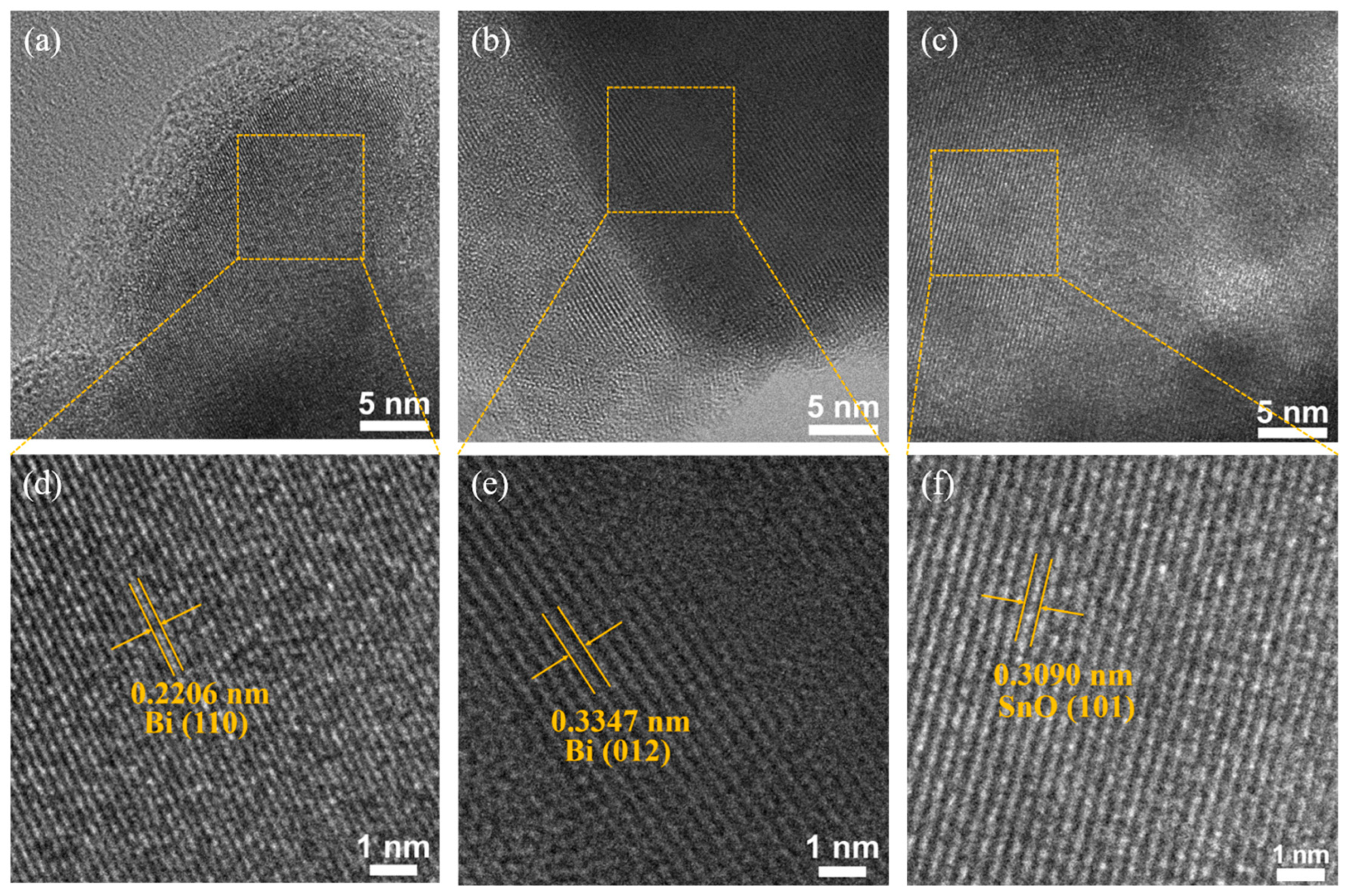
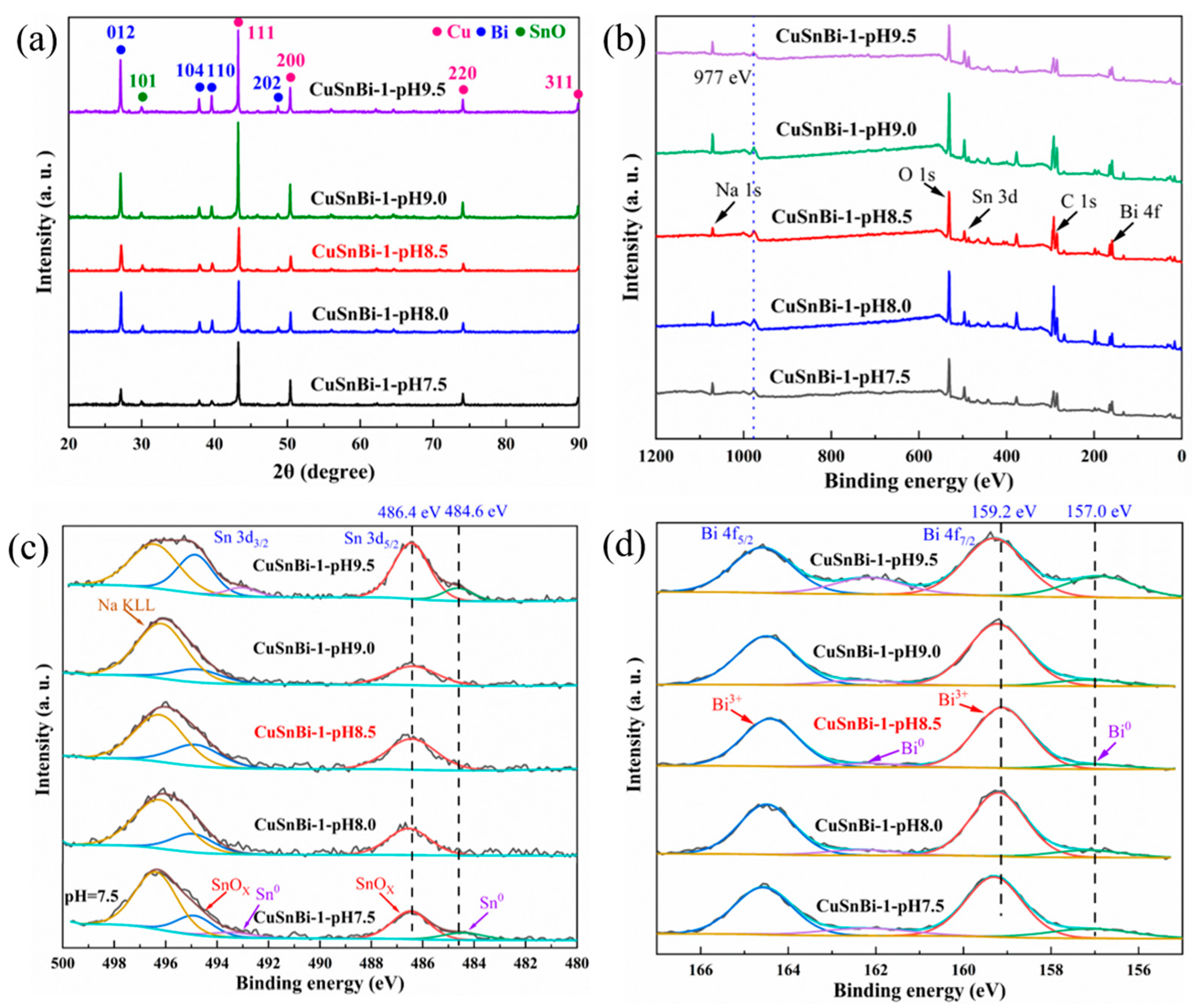
2.1. Morphological and Structural Characterization

First, we performed SEM on the original and pretreated copper foams. As shown in Figure S1, the pretreated copper foam retained the scale-like structure of the original copper foam. After the pretreatment, the fibrous structure of the copper foam was exposed, which facilitated the electrodeposition of metal ions. Subsequently, XRD and XPS analyses were performed on the pretreated copper foam substrates. The observed diffraction peaks at 43.3°, 50.4°, 74.1°, and 89.9° were assigned to the (1), (200), (220), and (311) planes of metallic Cu, respectively (Figure S2a), according to the standard PDF card (JCPDS PDF# 04–0836) [23,24]. In the Cu 2p XPS spectra (Figure S2b), the bands at 932.69 and 952.47 eV were attributed to Cu 2p3/2 and Cu 2p1/2 of Cu+ or Cu0 [21,28,29]. It was difficult to distinguish Cu+ from Cu0 in the Cu 2p peak because the two species exhibit similar binding energies. Thus, the surface state was further analyzed using a Cu LMM Auger peak (Figure S2c). Previous investigations have shown that the Auger peak energy positions of Cu2O (Cu+) and Cu (Cu0) are 916.2 and 918.6 eV, respectively [29,30]. The pretreated copper foam with a Cu2O surface is an excellent substrate for catalysts, conducive to the growth of metal ions [3,4].
SEM was used to investigate the morphology of the catalytic electrodes. Successful growth of catalysts on the derived Cu foam substrates is confirmed in Figure 1 and Figures S3–S6. Catalytic electrodes show large cracks, likely resulting from the flake-like structure of the pretreated copper foam, which hindered the lateral growth of catalysts. The catalysts are preferentially deposited on the exposed fibrous structure of the copper foam, forming hilly bulges. Hence, electrodes fabricated at various pH values of the deposition solution exhibit similar hilly protrusions covered with numerous spherical particles. This structure helped expose more catalytically active sites. EDS elemental maps in Figure 1 and Figures S3–S6 indicate that Cu, Sn, and Bi are fairly evenly distributed on the electrode surface, with the Cu content being significantly lower than those of Sn and Bi. This suggests that the electrodes are predominantly composed of Sn and Bi, with Cu present in smaller amounts.
TEM was employed to further observe the microstructure of the prepared catalytic electrodes (Figure 2 and Figure S7). The lattice spacings were determined as 0.2206 and 0.3347 nm, closely corresponding to the (110) and (012) crystal planes of Bi, as indicated by the XRD patterns (Figure 3a) [31,32,33]. The lattice spacings were measured to be 0.3090 nm, which corresponds closely to the (101) crystal planes of SnO. Many studies have shown that the Bi (012) and (110) crystal planes can stabilize OCHO* intermediates and suppress H2 formation, promoting the conversion of CO2 to formate [8,34,35,36]. The distributions of Cu, Sn, and Bi in the CuSnBi–1–pH8.5 electrode are shown in Figure S7. The three elements are distributed evenly, and the response intensities of Bi and Cu exceed that of Sn. Moreover, the weight percentages (wt%) of Cu, Sn, and Bi in this electrode are 19.5, 12.95, and 67.55, and the atomic percentages (σ%) are 41.51, 14.76, and 43.73, respectively, as shown in Figure S8.
XRD was utilized to study the crystalline structure of the CuSnBi trimetallic catalytic electrodes. Four peaks at 27.2°, 38.0°, 39.6°, and 48.7° correspond to the Bi (012), (104), (110), and (202) crystal planes, respectively, according to the standard card (JCPDS PDF# 85–1329) [25]. The weak peak at 29.9° was assigned to the (101) plane of SnO, matching the standard card (JCPDS PDF# 86–0395) [20]. Based on the standard card (JCPDS PDF# 04–0673) [20], the diffraction peaks at 30.6° and 32.0° correspond to the Sn (200) and (101) crystal planes, respectively. Based on the spectrum of the pretreated copper foam substrate (Figure S2a), the peaks of the Cu crystal plane in the catalytic electrodes were attributed to the foam substrate (Figure 3a and Figure S9). Only very weak diffraction peaks associated with Sn are observed in the XRD pattern. Combined with the SEM and TEM EDS results, this suggests that Sn is primarily in the amorphous state. The peaks of the Bi (012) plane are considerably stronger than those of the other Bi planes. Notably, the presence of the (012) plane of Bi is beneficial for formate selectivity [8,34,35,36].
XPS of CuSnBi electrodes was conducted to determine the surface composition and chemical state (Figure 3). In the Bi 4f XPS spectra, the peaks at 159.11 and 164.41 eV were assigned to Bi3+ 4f7/2 and 4f5/2, whereas the peaks at 157.08 and 162.18 eV were attributed to Bi0 4f7/2 and 4f5/2, respectively [21,24,25]. In the Sn 3d XPS spectra, the peaks at 486.43 and 394.83 eV were attributed to SnOx 3d5/2 and 3d3/2, and the peaks at 484.64 and 493.04 eV were assigned to Sn0 3d5/2 and 3d3/2, respectively [25]. Sn 3d3/2 peaks partially overlap with the Na KLL Auger signal [37,38], where Na originates from Na2HPO4, EDTA-2Na, NaKC4H4O6·5H2O, and Na3C6H5O7 in the electrodeposition solution. Moreover, no peaks attributed to Cu species are detected, indicating a low amount of Cu present, and the electrode’s surface is mainly composed of Sn and Bi. Few shifts are observed in the Bi-related peaks of the CuSnBi–1–pH8.5 electrode, whereas the corresponding peaks of Bi in the other electrodes shift to higher binding energies. This suggests the occurrence of electron redistribution after metal doping. The electronegativity of the three metals follows the order Cu > Bi > Sn. This results in electron transfer from Sn to Bi and Cu and from Bi to Cu. The electronic structure of the active sites is adjusted at the interface of the three metals, creating a localized electronic environment that promotes improved interaction between the sites and the *OCHO intermediate [8,39].
Previous studies have shown that SnOx has a stronger adsorption capacity for *OCHO intermediates than Sn0, which promotes formate formation [12,14,20,40]. The Bi–O structure in the Bi composites is more favorable for the selective reduction of CO2 to formate [8,17,18,41,42]. For example, Wang et al. [43] conducted in situ Fourier transform infrared spectroscopy to reveal that metal oxides (SnO2 and Bi2O3) in the catalysts enhanced the adsorption of CO2 and continuously facilitated the transformation of *OCHO intermediates. At the same time, Deng et al. [17] have shown, using density functional theory calculations, that the Bi–O structure in the Bi2O3 catalyst exhibits a higher affinity for CO2 adsorption than pure Bi. XPS revealed that the surface of the catalytic electrodes was primarily composed of Sn and Bi oxides. This composition suggests that the CuSnBi catalytic electrode exhibits promising performance in the electrochemical reduction of CO2 to HCOO. A higher oxide content is anticipated to correspond to better performance, a relationship that was confirmed in subsequent experiments.
To further illustrate the differences in the elemental composition of catalytic electrodes prepared at different pH levels of the electrodeposition solution, the atomic ratio of Sn to Bi in the electrodes was calculated based on the areas of these peaks (Table S1). The pH of the electrodeposition solution affects the composition of the catalytic electrode, thereby impacting its performance in the electrochemical reduction of CO2 to HCOO. With the increase in the pH value of the electrodeposition solution, the contents of Bi and Bi oxide on the electrode surface initially increase and then decrease. A high oxide content is advantageous for formate production. The CuSnBi–1–pH8.5 electrode exhibits the highest FEHCOO, attributed to its highest Bi content (atomic ratio Sn:Bi = 1:2.15) and the highest proportion of Bi oxide (62.03%) [17,44].

2.2. Electrochemical Performance

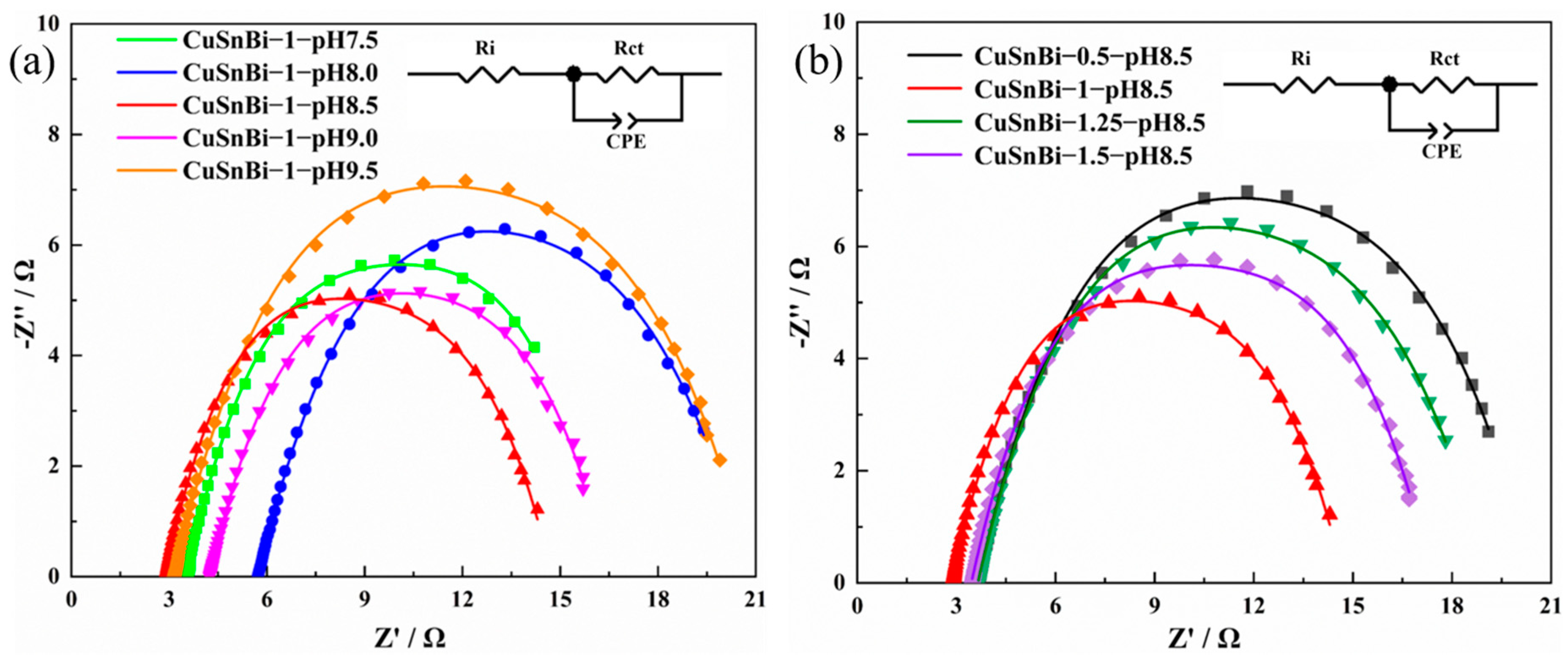
2.2.1. Effect of pH of the Electrodeposition Solution on the Catalyst Activity

First, linear sweep voltammetry (LSV) was performed over the electrodes to assess their activity in the electrochemical reduction of CO2. As shown in Figure 4a, in the identical potential, a significant difference in current density emerges between the CO2 and Ar-saturated electrolytes. This discrepancy signifies the exceptional catalytic activity of the CuSnBi electrodes in the electroreduction of CO2. The current density decreases in the following order: CuSnBi–1–pH8.5 > CuSnBi–1–pH9.5 > CuSnBi–1–pH7.5 ≈ CuSnBi–1–pH8.0 > CuSnBi–1–pH9.0, indicating that the CuSnBi–1–pH8.5 electrode exhibits the best CO2 reduction activity. Meanwhile, the pH of the electrodeposition solution has little effect on the catalytic activity of the electrodes. This was attributed to the similar hilly convex structures of the electrodes and robust Bi (104) crystal plane.
The electrochemically active surface area (ECSA) is an important parameter for assessing and comparing the intrinsic electrocatalytic activities of electrodes [45]. Double-layer capacitance (Cdl) is currently the most popular method for measuring the ECSA of metal oxides [5]. The Cdl value reflects the ECSA of the electrode because Cdl is directly proportional to ECSA [8,24]. Herein, Cdl was calculated from CV curves obtained at different scan rates within a non-Faradaic interval (0.19–0.29 VRHE). According to the results in Figure 4b, the ECSA decreases in the following order: CuSnBi–1–pH8.5 ≈ CuSnBi–1–pH9.5 > CuSnBi–1–pH8.0 > CuSnBi–1–pH7.5 > CuSnBi–1–pH9.0, suggesting that CuSnBi–1–pH8.5 and CuSnBi–1–pH9.5 electrodes exhibit the best catalytic activity. The results agree well with the results derived from the LSV curves.
To evaluate the effect of the electrolytic potential on FEHCOO, the electrocatalytic reduction of CO2 was conducted for 1 h in a potential range from −0.82 to −1.32 VRHE in CO2-saturated 0.5 M KHCO3. As shown in Figure 4c, FEHCOO exhibits a characteristic volcano-like trend in the tested potential range. At −1.12 VRHE, the FEHCOO of the electrodes first increases and then decreases with increasing pH value of the electrodeposition solution. The FEHCOO decreases in the following order: CuSnBi–1–pH8.5 ≈ CuSnBi–1–pH9.5 > CuSnBi–1–pH8.0 > CuSnBi–1–pH7.5 > CuSnBi–1–pH9.0, which is in accordance with the LSV curves and the content of Bi oxide in the electrodes. The CuSnBi–1–pH8.5 electrode shows a maximum FEHCOO of 93.08% with a formate partial current density of 27.9 mA·cm−2 at −1.02 VRHE. Additionally, the FEHCOO of the electrode exceeds 90% at potentials of −0.92 to −1.12 VRHE and a partial current density of 36.6 mA·cm−2 at −1.12 VRHE. Consistent with the XPS results, more Bi on the surface promotes the conversion of CO2 to HCOO.

2.2.2. Effects of the Cu2+:Sn2+:Bi3+ Molar Ratio in the Electrodeposition Solutions on the Catalyst Activity

The effect of the molar ratios of metal ions in the electrodeposition solution on the electrochemical performance of the catalytic electrodes was explored while maintaining the pH constant.
The LSV results are shown in Figure S10a. The current density exhibited by the CuSnBi–1–pH8.5 catalytic electrode significantly surpasses those of other electrodes within the CO2 reduction potential range. The LSV curves for other electrodes are similar. This implies that the CuSnBi–1–pH8.5 electrode exhibits the highest activity in the electrochemical CO2 reduction.
The Cdl values of the catalytic electrodes were obtained using the same method (Figure S10b). The Cdl value initially increases but then decreases with an increasing molar concentration of Sn2+ in the electrodeposition solution. The experimental results indicate that the CuSnBi–1–pH8.5 electrode has the highest ECSA and exhibits the best catalytic performance, which agrees with the findings presented in Figure S10a.
The data for FEHCOO and FEH2 are shown in Figure S10c,d. At −1.12 VRHE, FEHCOO exhibits a distinctive volcano-shaped trend with the increase of Sn2+ concentration in the electrodeposition solution. Obviously, the performance of the CuSnBi–1–pH8.5 electrode is the best in the potential range from −0.92 to −1.32 VRHE.

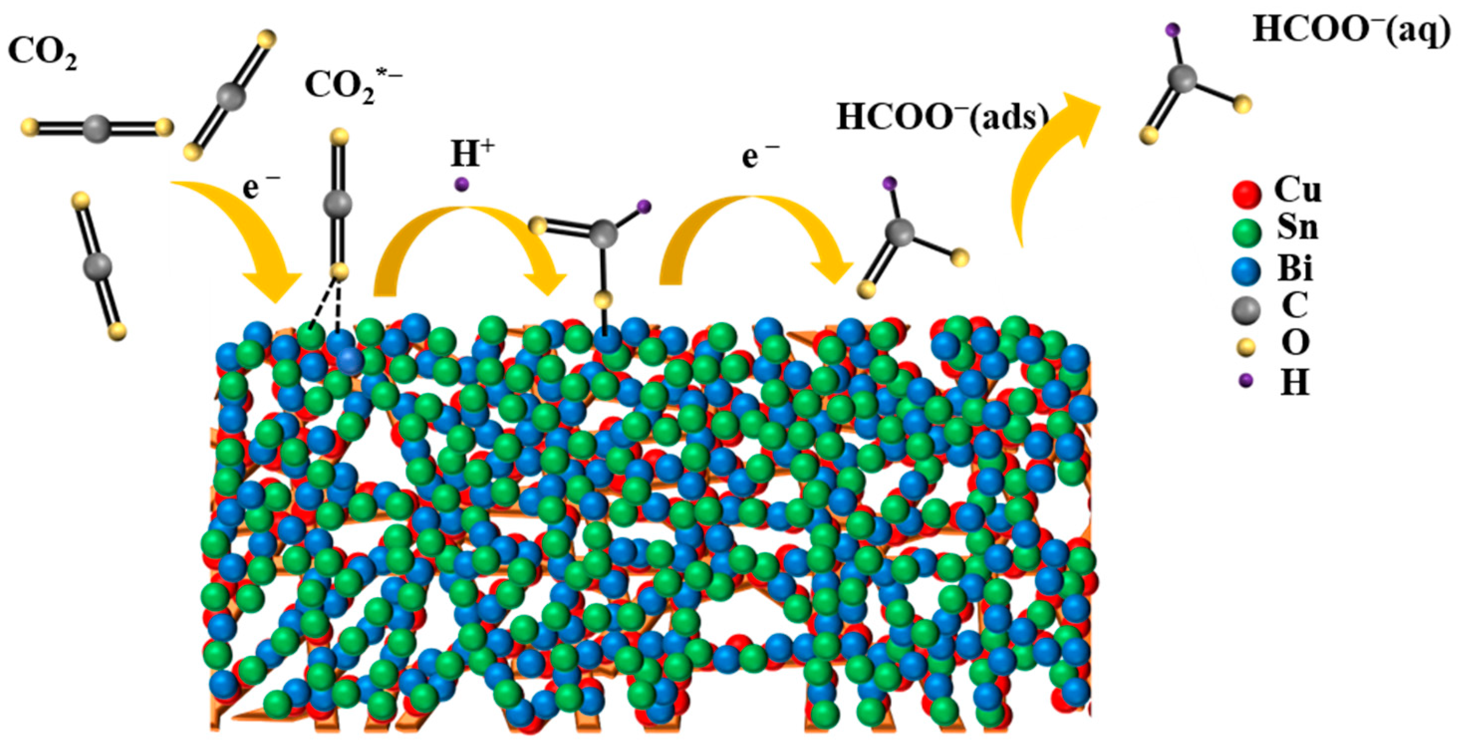
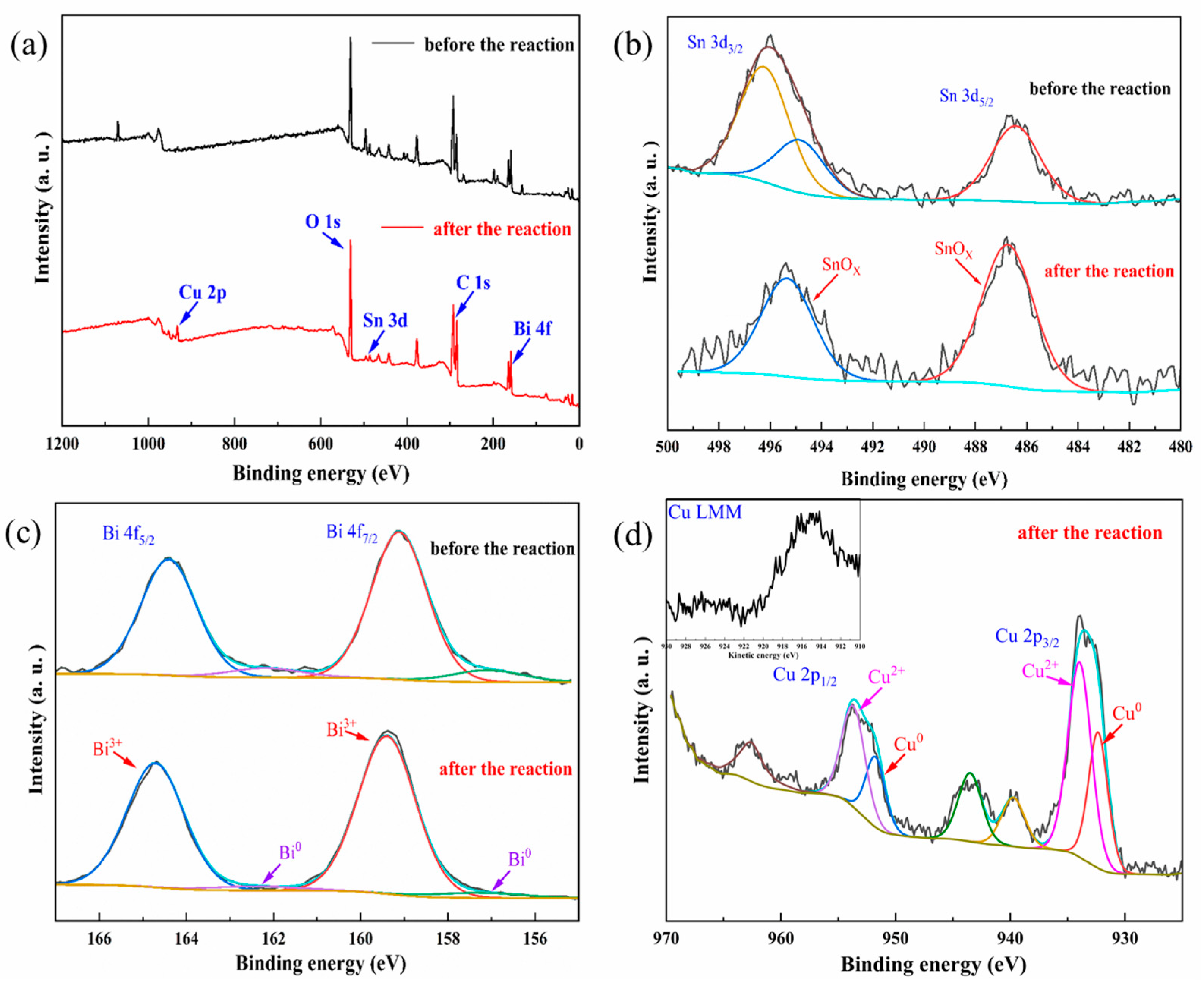
2.3. Mechanism of CO2 Electroreduction on the CuSnBi Electrodes

Electrochemical impedance spectroscopy (EIS) measurements were used to investigate the mechanism of CO2 reduction. Figure 5a,b shows the Nyquist curves derived by fitting the equivalent circuit to the EIS data, and the fitting parameters are shown in Tables S3 and S4. Copper foam has high electrical conductivity, and no binder was used to synthesize the electrodes, facilitating swift electron transfer between the copper foam substrate and the catalyst interface [26]. Therefore, the use of copper foam is beneficial for the charge transfer steps in the mechanism. As shown in Figure 5a, the pH value has a certain effect on the Ri of the electrode, and the CuSnBi–1–pH8.5 electrode exhibits minimum Ri and Rct. The molar ratio of metal ions has practically no effect on Ri, whereas Rct shows a volcano-shaped trend with increasing molar concentration of Sn2+, as shown in Figure 5b. The electrode prepared at the Cu2+:Sn2+:Bi3+ ratio of 1:1:1 exhibits the fastest charge transfer. The low Rct indicates that the charge transfer between the electrode and the electron acceptor is fast, and the activation polarization loss during the electroreduction of CO2 is small [25,44]. Hence, the CuSnBi–1–pH8.5 electrode, obtained at the pH of the electrodeposition solution of 8.5 and the Cu2+:Sn2+:Bi3+ molar ratio of 1:1:1, exhibits the most favorable charge transfer kinetics.
The commonly held belief was that the mechanistic pathway for CO2 reduction to formate could be outlined as follows [8,10].
CO 2   ( aq ) + e CO 2 * ( ads )
CO 2 * ( ads ) + H + OCHO * ( ads )
OCHO * ( ads ) + e HCOO ( ads )
HCOO ( ads ) HCOO ( aq )
Equation (1) indicates that a CO2 molecule in the vicinity of the catalyst gains the first electron to form an adsorbed CO2* intermediate. Subsequently, the intermediate obtains a proton (H+) from the solution, forming adsorbed OCHO* (Equation (2)), a key intermediate. The key intermediate acquires the second electron from the electrode to generate the target product (Equation (3)), formate. Finally, the adsorbed HCOO is desorbed from the electrode and enters the solution (Equation (4)). The mechanism of CO2 electroreduction on CuSnBi electrodes is shown in Figure 6. Based on previous research, the initial electron transfer is the rate-determining step in the catalytic reduction of CO2 on the CuSnBi electrode [21,22,23,24,25].

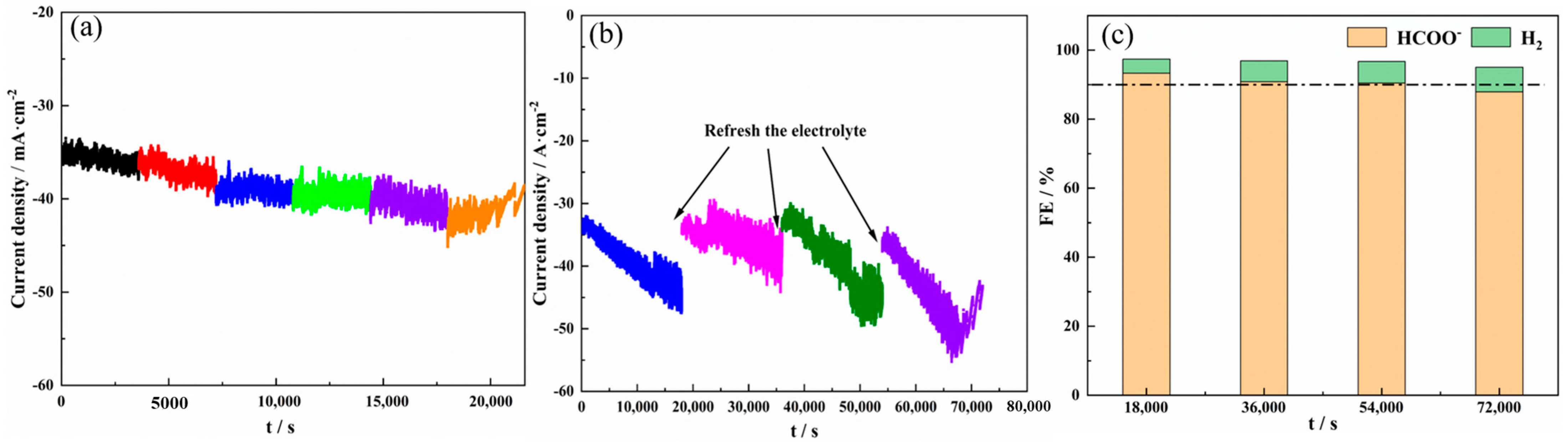
2.4. Electrode Stability in CO2 Electroreduction

Electrode stability is an important parameter for practical applications. Herein, chronoamperometry was used to evaluate the stability of CuSnBi electrodes in the electrocatalytic process [8]. The CuSnBi–1–pH8.5 electrode prepared using the optimal electrodeposition conditions was selected for stability studies. At −1.12 VRHE, the electrode maintains stable performance for nearly 6 h, as shown in Figure 7a. At the 6th hour, the current density fluctuates, which may be due to catalyst poisoning [19] or a change in the electrolyte composition [46]. We conducted stability measurements for an additional 20 h, with electrolyte replacement every 5 h during the testing period. As shown in Figure 7b, after replacing the electrolyte, the current density returns to its initial value. Thus, the above fluctuation in the current density occurs owing to changes in the electrolyte rather than in the catalyst. During the initial 15 h, the CuSnBi–1–pH8.5 electrode maintains a FEHCOO of over 90% (Figure 7c). Although the FEHCOO decreases to 87.91% after the third electrolyte refresh, the FEHCOO is always beyond 85% throughout the electrolysis process.
The XPS of the CuSnBi–1–pH8.5 electrode was performed after the stability test to study the changes in the composition of the electrode surface. Cu content on the electrode surface is too low to be detected in the XPS spectrum before the reaction. However, Cu is detected on the electrode surface after the reaction, and the Cu 2p fine spectra show a shift of the peaks to lower binding energies (Figure 8). A noticeable shift toward higher binding energies is observed in the relevant peaks of Bi 4f and Sn 3d fine spectra after the stability test (Figure 8b,c). Based on the electronegativities of the three metals, it was inferred that the electrons were transferred from Sn and Bi to Cu. Furthermore, the peak areas in the XPS spectra were integrated to determine the proportion of each species, and the results are presented in Table S2. Table S2 shows that the proportion of metal oxides on the surface of the electrode was significantly reduced. After the stability test, the proportion of Sn oxide decreased from 31.74% to 9.42%, and the proportion of Bi oxide declined from 62.03% to 32.45%. The high content of Sn and Bi oxides is crucial for superior performance. The degradation in catalytic electrode performance is primarily attributed to the reduction in the oxide content of these elements. Although the Sn and Bi oxides on the electrode surface have decreased sharply, FEHCOO is still maintained above 85% after 20 h of electrolysis. This phenomenon could be attributed to the exposure of copper, and previous literature has also demonstrated that Cu-based catalysts can obtain good formate selectivity [20,21,22,23].
The change in the surface composition of the catalytic electrode after long-time electrolysis resulted in a decrease in the selectivity toward formate. The KHCO3 electrolyte maintains a CO2/HCO3 balance, which helps stabilize the neutral pH of the electrolyte. As the reaction progresses, a pH gradient forms near the electrode. This pH gradient affects the concentration of CO2 in the vicinity of the electrode and leads to catalyst recombination and corrosion [3,46]. These factors ultimately affect the activity and selectivity of the electrode catalyst. Overall, the CuSnBi–1–pH8.5 electrode exhibits remarkable stability for 20 h at a potential of −1.12 VRHE, which is excellent performance compared to the previously reported ternary metal catalyst (Table S5).

3. Materials and Methods

3.1. Materials

Potassium chloride (KCl, 99.5%), stannous pyrophosphate (Sn2P2O7, >95%), formic acid (HCOOH, ≥99%), and ethanol (CH3CH2OH, ≥99.7%) were purchased from Shanghai Macklin Biochemical Co., Ltd. (Shanghai, China) Disodium hydrogen phosphate (Na2HPO4, 99%), ethylenediaminetetraacetic acid disodium salt (EDTA-2Na, 98%), potassium pyrophosphate (K4P2O7, 98%), potassium sodium tartrate (NaKC4H4O6·5H2O, 99%), sodium citrate (Na3C6H5O7, 98%), bismuth nitrate (Bi(NO3)3·5H2O, ≥99%), copper pyrophosphate hydrate (Cu2P2O7·xH2O, 99%), and potassium bicarbonate (KHCO3, 99.5%) were purchased from Shanghai Aladdin Biochemical Technology Co., Ltd. (Shanghai, China) Potassium hydroxide (KOH, 85%) was purchased from Beijing InnoChem Science & Technology Co., Ltd. (Beijing, China) Argon (Ar, 99.999%), nitrogen (N2, 99.999%), carbon dioxide (CO2, 99.9%), and hydrogen (H2, 0.1%, 0.5%, 3%, and 5%) were purchased from Beijing Haipu Gas Co., Ltd. (Beijing, China) The copper foams used in this study were obtained from Guangjiayuan New Material Co., Ltd. (Kunshan, China)The copper foams had a pore size of 5–45 μm (10–130 ppi) and a porosity of 75–98%. The Nafion-117 proton exchange membrane was purchased from DuPont Co. (Shanghai, China) Graphite sheets (10 mm × 20 mm), platinum sheet electrodes (20 mm × 20 mm × 0.1 mm), and Ag/AgCl reference electrodes were purchased from Tianjin Gaoshiruilian Photoelectric Technology Co., Ltd. (Tianjin, China).

3.2. Preparation of the Pretreated Copper Foam Substrate

Chemical methods were used to pretreat the original copper foam substrates (thickness: 0.3 mm). First, the original copper foam (10 mm × 15 mm) was immersed in 0.1 M HCl solution for 1 h to eliminate copper oxides. Subsequently, it was rinsed several times with deionized water and patted dry using absorbent paper. It was then submerged in hydrous ethanol for 1 h to eliminate any organic residues. Finally, the treated substrates were heated in an oven at 125 °C for 1 h.

3.3. Fabrication of the CuSnBi Trimetallic Electrode

The CuSnBi catalyst was deposited on the pretreated Cu foam substrates via simple co-electrodeposition to obtain CuSnBi trimetallic electrodes. First, 3 g KCl (40.24 mmol) was mixed with 2.5 g Na2HPO4 (17.61 mmol) in 50 mL of deionized water at 60 °C under stirring until complete dissolution. Then, 4.5 g EDTA-2Na (12.09 mmol), 16 g K4P2O7 (48.43 mmol), 3 g NaKC4H4O6·5H2O (10.63 mmol), 3 g Bi(NO3)3·5H2O (6.18 mmol), 6 g Na3C6H5O7 (23.25 mmol), 0.636–1.908 g Sn2P2O7 (1.55–4.64 mmol), and 0.932 g Cu2P2O7·xH2O (3.10 mmol) were sequentially added. The molar ratio of Cu2+:Sn2+:Bi3+ was 1:x:1 (x is 0.5, 1, 1.25, and 1.5), and the pH value y of the electrodeposition solution was adjusted to y (y is 7.5, 8.0, 8.5, 9.0, and 9.5) using 0.5 M KOH and 0.5 M HCl. The resulting catalytic electrode is denoted as CuSnBi–x–pHy. The CuSnBi trimetallic electrode was prepared in a two-electrode system. The pretreated copper foam substrate with an effective area of 1 cm2 was employed as the working electrode, and a graphite sheet was used as the counter electrode. The CuSnBi catalyst was obtained through co-electrodeposition for 3600 s at a current density of 7 mA·cm−2. After electrodeposition, the resulting trimetallic catalytic electrodes were rinsed multiple times with deionized water and were subsequently dried in a vacuum drying oven at 50 °C for 4 h.

3.4. Material Characterization

The structures of the catalytic electrodes were characterized using X-ray diffraction (XRD, SmartLab SE, Tokyo, Japan) at room temperature. The indices of crystallographic planes were matched with the standard PDF card using Jade 6 software (version number: 6.2.9200). The surface chemical composition and valence states of the electrodes were analyzed using X-ray photoelectron spectroscopy (XPS, Thermo Scientific K-Alpha, Waltham, MA, USA) with an Al Ka X-ray source. All binding energies were referenced to C1s (284.8 eV). The surface of the electrodes was observed using scanning electron microscopy (SEM, TESCAN MIRA LMS, Brno, Czech Republic) equipped with energy dispersive X-ray spectroscopy (EDS) probe and via transmission electron microscopy (TEM, JEOL JEM-F200, Tokyo, Japan).

3.5. Electrochemical Measurements

Electrochemical measurements were performed using an electrochemical workstation (CHI660e, Shanghai, China) in a standard H-type cell with a Nafion 117 proton exchange membrane separating the two compartments. Before utilizing it in the KHCO3 solution, the Nafion 117 membrane was converted into K+ form. A platinum sheet was used as a counter electrode, while an Ag/AgCl electrode saturated with KCl was used as a reference electrode. Both compartments contained 50 mL of the 0.5 M KHCO3 solution that had been saturated with CO2 for 30 min before electrochemical testing. It should be noted that the gas flow rate was maintained at 20 mL/min during the experiment. All potentials were measured relative to the reversible hydrogen electrode (RHE) and calculated using Equation (5).
E (vs. RHE) = E (vs. Ag/AgCl) + 0.197 + 0.059 × pH
The pH value of 0.5 M KHCO3 solution saturated with CO2 was 7.4. All experiments were performed at 25 °C under ambient pressure.
All electrochemical performance tests were conducted in a typical H-type electrolytic cell. The gas was continuously fed into a 0.5 M KHCO3 cathode electrolyte during electrochemical tests. LSV curves were obtained from −0.4 to −1.6 VRHE at 50 mV·s−1. Ar was used as a reference gas for CO2 reduction, and LSV curves were first carried out at N2 saturated conditions. Next, the N2 air flow was stopped and LSV curves were measured at CO2 saturated conditions. CV curves were recorded with selected potential windows (0.19–0.29 VRHE) using different scan rate values (40, 80, 120, 160 and 200 mV·s−1). Cdl was calculated by the slope of scan rates and redox current. EIS was used to prove the influence of impedance for CO2 reduction performance. AC impedance mode was operated in a frequency range from 0.1 to 100,000 Hz at a selected potential (−0.72 VRHE). Amperometric i-t curve mode was employed to evaluate the performance of CO2 electroreduction of materials, and i-t curves were recorded at different potentials (−0.82, −0.92, −1.02, −1.12, −1.22 and −1.32 VRHE) for 1 h.

3.6. Product Analysis

Liquid products were analyzed using ion chromatography (IC, Dionex ICS-600, Sunnyvale, CA, USA). The liquid samples were diluted 100-fold with ultrapure water. The expression for FEHCOO given in Equation (6) is based on the fact that two electrons must be transferred to produce one HCOO.
FE HCOO % = 2 × n × F Q
Here, F is Faraday’s constant (96,485 C·mol−1), n denotes the moles of HCOO produced, and Q represents the total charge involved in a particular reaction over a specific time.
The gas products were analyzed using gas chromatography (GC-9720plus, Wenling, China) with a thermal conductivity detector. High-purity Ar was used as a carrier gas. Gas samples collected from the cathode chamber outlet were introduced into the gas chromatograph through an autosampler for analysis. The Faradaic efficiency of the gas products was calculated using Equation (7).
FE gas % = N × c × v × t V m × F Q
where N is the number of electrons transferred from one CO2 molecule to H2/CO or other gas products, c is the percentage of the volume of this gas relative to the total gas volume, v is the CO2 flow rate from the gas outlet of the H-type cell measured using a gas flowmeter, t is the time of electrolysis, and Vm is the molar volume of a gas, which is typically 22.4 L/mol.

4. Conclusions

The CuSnBi catalytic electrodes were grown on a copper foam substrate via simple electrodeposition from solutions with different formulations (pH value and Cu2+:Sn2+:Bi3+ molar ratio). This work investigated the effects of both factors on the morphology, composition, capacitance, impedance, current, and Faradaic efficiency of the catalytic electrodes. The relationship between the formulations of the electrodeposition solution and the composition and performance of the electrodes was established, providing valuable theoretical and experimental insights into the controlled growth of ternary metal catalysts on Cu substrates. When the pH value of the electrodeposition solution was 8.5 and the molar ratio of Cu2+, Sn2+, and Bi3+ was 1:1:1, the prepared electrode exhibited a high FEHCOO of 91.79% with the formate partial current density of 36.6 mA·cm−2 at −1.12 VRHE. Such excellent performance was attributed to the Bi (012) crystal plane orientation, fast charge transfer, and high Bi oxide content, which promotes the binding of active sites to the OCHO* intermediate. In the stability test, this electrode showed excellent stability for 20 h at −1.12 VRHE with FEHCOO maintained above 85% throughout the electrolysis. Notably, the fluctuation in current density occurred primarily because of changes in the electrolyte. Hence, continuous replacement of the electrolyte is necessary to maintain the high activity and selectivity of the catalyst in the conversion of CO2 to HCOO. Furthermore, these results reveal that it is very important to maintain the electrolyte stable for sustaining the stability of electrochemical processes. Mul-metallic catalysts are promising CO2 catalysts, but they still need to be further refined to ensure the synergy between the components. Furthermore, the influence of electrolyte changes on catalysts during CO2 electroreduction needs to be further explored.

Supplementary Materials

The following supporting information can be downloaded at https://www.mdpi.com/article/10.3390/catal14030191/s1, Figure S1: SEM image of (a) and (c) original Cu foam, (b) and (d) pretreated Cu foam; Figure S2: Spectrum of the derived Cu foam. (a) XRD patterns, (b) XPS fine spectra of Cu, and (c) Auger spectra of Cu; Figure S3: SEM images of the CuSnBi–1–pH7.5 electrode with scale bars of (a) 10 μm, (b) 2 μm, and (c) 200 nm. (d) Elemental map (Bi is blue, Sn is green, and Cu is red); Figure S4: SEM images of the CuSnBi–1–pH8.0 electrode with scale bars of (a) 10 μm, (b) 2 μm, and (c) 200 nm; Figure S5: SEM images of the CuSnBi–1–pH9.0 electrode with scale bars of (a) 10 μm, (b) 2 μm, and (c) 200 nm. (d) Elemental map (Bi is blue, Sn is green, and Cu is red); Figure S6: SEM images of the CuSnBi–1–pH9.5 electrode with scale bars of (a) 10 μm, (b) 2 μm, and (c) 200 nm. (d) Elemental map (Bi is blue, Sn is green, and Cu is red); Figure S7: TEM-EDS mapping results of CuSnBi–1–pH8.5 electrode; Figure S8: TEM-EDS spectrum of CuSnBi–1–pH8.5 electrode; Figure S9: XRD patterns of the CuSnBi–x–pH8.5 electrodes prepared at different molar ratios of Cu2+/Sn2+/Bi3+ in electrodeposition solution; Figure S10: Electrochemical characterization of CuSnBi–1x1–pH8.5 electrodes prepared at different molar ratios of Cu2+/Sn2+/Bi3+. (a) LSV, (b) Cdl, (c) FEHCOO, and (d) FEH2; Table S1: Percentage of bismuth and tin species in CuSnBi–1–pHy electrodes prepared at different pH values; Table S2: Percentage of metal species in the CuSnBi–1–pH8.5 electrode before and after the stability test; Table S3: Fitting equivalent circuit parameters in CuSnBi–1–pHy electrodes prepared at different pH values; Table S4: Fitting equivalent circuit parameters in CuSnBi–x–pH8.5 electrodes prepared at different molar ratios of Cu2+/Sn2+/Bi3+ in electrodeposition solution; Table S5: Performance summary of recent ternary metal catalysts for electrochemical reduction of carbon dioxide [47,48,49,50,51,52,53].

Author Contributions

Conceptualization, L.L. and Y.S.; methodology, H.X.; validation, H.X.; formal analysis, M.T.; investigation, H.X. and M.T.; resources, C.W. and Y.S.; data curation, H.X. and J.X.; writing—original draft preparation, H.X.; writing—review and editing, L.L. and Y.S.; visualization, H.X.; supervision, H.X. and M.T.; project administration, L.L.; funding acquisition, C.W. and Y.S. All authors have read and agreed to the published version of the manuscript.

Funding

This research received no external funding.

Data Availability Statement

Data are contained within the article and the Supplementary Materials.

Conflicts of Interest

The authors declare no conflicts of interest.

References

  1. Gulzar, A.; Gulzar, A. Carbon Dioxide Utilization: A Paradigm Shift with CO2 Economy. Chem. Eng. J. Adv. 2020, 3, 100013. [Google Scholar] [CrossRef]
  2. Bulushev, D.A.; Ross, J.R. Towards Sustainable Production of Formic Acid. ChemSusChem 2018, 11, 821–836. [Google Scholar] [CrossRef] [PubMed]
  3. Duarah, P.; Haldar, D. Progress in the Electrochemical Reduction of CO2 to Formic Acid: A Review on Current Trends and Future Prospects. J. Environ. Chem. Eng. 2021, 9, 106394. [Google Scholar] [CrossRef]
  4. Ma, Z.; Legrand, U. From CO2 to Formic Acid Fuel Cells. Ind. Eng. Chem. Res. 2021, 60, 803–815. [Google Scholar] [CrossRef]
  5. Onishi, N.; Iguchi, M. Development of Effective Catalysts for Hydrogen Storage Technology Using Formic Acid. Adv. Energy Mater. 2019, 9, 1801275. [Google Scholar] [CrossRef]
  6. Jouny, M.; Luc, W. General Techno-Economic Analysis of CO2 Electrolysis Systems. Ind. Eng. Chem. Res. 2018, 57, 2165–2177. [Google Scholar] [CrossRef]
  7. Kim, S.; Shin, H. Electrochemical Reduction of Captured CO2: A Route toward the Integrated Carbon Capture and Utilization. Curr. Opin. Electrochem. 2023, 40, 101321. [Google Scholar] [CrossRef]
  8. Wang, Y.; Jiang, W. Advances in Electrochemical Reduction of Carbon Dioxide to Formate over Bismuth-Based Catalysts. Rare Met. 2021, 40, 2327–2353. [Google Scholar] [CrossRef]
  9. Liang, S.; Altaf, N. Electrolytic Cell Design for Electrochemical CO2 Reduction. J. CO2 Util. 2020, 35, 90–105. [Google Scholar] [CrossRef]
  10. Zhang, Y.; Li, F. Recent Advances in Designing Efficient Electrocatalysts for Electrochemical Carbon Dioxide Reduction to Formic Acid/Formate. J. Electroanal. Chem. 2023, 928, 117018. [Google Scholar] [CrossRef]
  11. Gawel, A.; Jaster, T. Electrochemical CO2 Reduction—The Macroscopic World of Electrode Design, Reactor Concepts & Economic Aspects. iScience 2022, 25, 104011. [Google Scholar]
  12. Proietto, F.; Patel, U. Electrochemical Conversion of CO2 to Formic Acid Using a Sn Based Electrode: A Critical Review on the State-of-the-Art Technologies and Their Potential. Electrochim. Acta 2021, 389, 138753. [Google Scholar] [CrossRef]
  13. Yang, Z.; Oropeza, F. P-Block Metal-Based (Sn, In, Bi, Pb) Electrocatalysts for Selective Reduction of CO2 to Formate. APL Mater. 2020, 8, 060901. [Google Scholar] [CrossRef]
  14. Zhao, S.; Li, S. Advances in Sn-Based Catalysts for Electrochemical CO2 Reduction. Nano-Micro Lett. 2019, 11, 62. [Google Scholar] [CrossRef]
  15. Li, P.; Yang, F. Nanoscale Engineering of P-Block Metal-Based Catalysts Toward Industrial-Scale Electrochemical Reduction of CO2. Adv. Energy Mater. 2023, 13, 2301597. [Google Scholar] [CrossRef]
  16. Chen, W.; Wang, Y. Electrocatalytic CO2 Reduction over Bimetallic Bi-Based Catalysts: A Review. CCS Chem. 2023, 5, 544–567. [Google Scholar] [CrossRef]
  17. Deng, P.; Wang, H. Bismuth Oxides with Enhanced Bismuth–Oxygen Structure for Efficient Electrochemical Reduction of Carbon Dioxide to Formate. ACS Catal. 2020, 10, 743–750. [Google Scholar] [CrossRef]
  18. Yang, J.; Wang, X. Bi-Based Metal-Organic Framework Derived Leafy Bismuth Nanosheets for Carbon Dioxide Electroreduction. Adv. Energy Mater. 2020, 10, 2001709. [Google Scholar] [CrossRef]
  19. Van Daele, K.; De Mot, B.; Kortlever, R.; Breugelmans, T. Sn-Based Electrocatalyst Stability: A Crucial Piece to the Puzzle for the Electrochemical CO2 Reduction toward Formic Acid. ACS Energy Lett. 2021, 6, 4317–4327. [Google Scholar] [CrossRef]
  20. Wu, J.; Bai, X. Multivalent Sn Species Synergistically Favours the CO2-into-HCOOH Conversion. Nano Res. 2021, 14, 1053–1060. [Google Scholar] [CrossRef]
  21. Peng, L.; Wang, Y. Separated Growth of Bi-Cu Bimetallic Electrocatalysts on Defective Copper Foam for Highly Converting CO2 to Formate with Alkaline Anion-Exchange Membrane beyond KHCO3 Electrolyte. Appl. Catal. B Environ. 2021, 288, 120003. [Google Scholar] [CrossRef]
  22. Lou, W.; Peng, L. CuBi Electrocatalysts Modulated to Grow on Derived Copper Foam for Efficient CO2-to-Formate Conversion. J. Colloid Interface Sci. 2022, 606, 994–1003. [Google Scholar] [CrossRef] [PubMed]
  23. Wang, J.; Zou, J. Heterostructured Intermetallic CuSn Catalysts: High Performance towards the Electrochemical Reduction of CO2 to Formate. J. Mater. Chem. A 2019, 7, 27514–27521. [Google Scholar] [CrossRef]
  24. Wang, J.; Ji, Y. Phase and Structure Modulating of Bimetallic CuSn Nanowires Boosts Electrocatalytic Conversion of CO2. Nano Energy 2019, 59, 138–145. [Google Scholar] [CrossRef]
  25. Yang, S.; Sun, Y. One-Step Co-Electrodeposition of SnBi for Efficient Electrochemical Reduction of Carbon Dioxide to Formic Acid. Catal. Sci. Technol. 2023, 13, 758–766. [Google Scholar] [CrossRef]
  26. Zhu, C.; Wang, Q. Rapid and Scalable Synthesis of Bismuth Dendrites on Copper Mesh as a High-Performance Cathode for Electroreduction of CO2 to Formate. J. CO2 Util. 2020, 36, 96–104. [Google Scholar] [CrossRef]
  27. Zheng, W.; Liu, M. Best Practices in Using Foam-Type Electrodes for Electrocatalytic Performance Benchmark. ACS Energy Lett. 2020, 5, 3260–3264. [Google Scholar] [CrossRef]
  28. Wang, Y.; Zhou, W. Unveiling the Activity Origin of a Copper-based Electrocatalyst for Selective Nitrate Reduction to Ammonia. Angew. Chem. Int. Ed. 2020, 59, 5350–5354. [Google Scholar] [CrossRef]
  29. Li, X.; Duan, G. Regulating Electrochemical CO2RR Selectivity at Industrial Current Densities by Structuring Copper@poly(Ionic Liquid) Interface. Appl. Catal. B Environ. 2021, 297, 120471. [Google Scholar] [CrossRef]
  30. Cai, R.; Sun, M.; Huang, B.; Yang, S. Engineering Cu(I)/Cu(0) Interfaces for Efficient Ethanol Production from CO2 Electroreduction. Chem 2024, 10, 211–233. [Google Scholar] [CrossRef]
  31. Jiang, X.; Wang, Q.; Wang, M. Interfacial Engineering of Bismuth with Reduced Graphene Oxide Hybrid for Improving CO2 Electroreduction Performance. Electrochim. Acta 2020, 357, 136840. [Google Scholar] [CrossRef]
  32. Chen, P.; Liu, H. Bi Metal Prevents the Deactivation of Oxygen Vacancies in Bi2O2CO3 for Stable and Efficient Photocatalytic NO Abatement. Appl. Catal. B Environ. 2020, 264, 118545. [Google Scholar] [CrossRef]
  33. Deng, Y.; Wang, J. In Situ Growth of Bi/Ag Double Quantum Dots on Hollow Bi2MoO6 Microspheres: Enhancement of the Surface Plasmon Resonance Effect on PMS Activation. Appl. Catal. B Environ. 2023, 338, 123041. [Google Scholar] [CrossRef]
  34. Peng, C.; Yang, S. Ampere-Level CO2-to-Formate Electrosynthesis Using Highly Exposed Bismuth(110) Facets Modified with Sulfur-Anchored Sodium Cations. Chem 2023, 9, 2830–2840. [Google Scholar] [CrossRef]
  35. Xie, H.; Zhang, T. Facet Engineering to Regulate Surface States of Topological Crystalline Insulator Bismuth Rhombic Dodecahedrons for Highly Energy Efficient Electrochemical CO2 Reduction. Adv. Mater. 2021, 33, 2008373. [Google Scholar] [CrossRef]
  36. Zhang, Y.; Zhang, R. Mass-Transfer-Enhanced Hydrophobic Bi Microsheets for Highly Efficient Electroreduction of CO2 to Pure Formate in a Wide Potential Window. Appl. Catal. B Environ. 2023, 322, 122127. [Google Scholar] [CrossRef]
  37. Chen, Z.; Löber, M. Increased Photocurrent of CuWO4 Photoanodes by Modification with the Oxide Carbodiimide Sn2O(NCN). Dalton Trans. 2020, 49, 3450–3456. [Google Scholar] [CrossRef]
  38. Dong, W.; Li, R. Long-Life and High Volumetric Capacity Anode with Interpenetrating Bi–O and Sn–O Networks. Cell Rep. Phys. Sci. 2022, 3, 101109. [Google Scholar] [CrossRef]
  39. Wen, G.; Lee, D. Orbital Interactions in Bi-Sn Bimetallic Electrocatalysts for Highly Selective Electrochemical CO2 Reduction toward Formate Production. Adv. Energy Mater. 2018, 8, 1802427. [Google Scholar] [CrossRef]
  40. Shi, Y.; Wang, Y. Superscalar Phase Boundaries Derived Multiple Active Sites in SnO2/Cu6Sn5/CuO for Tandem Electroreduction of CO2 to Formic Acid. Adv. Energy Mater. 2023, 13, 2203506. [Google Scholar] [CrossRef]
  41. Liu, S.; Fan, Y. Surface-Oxygen-Rich Bi@C Nanoparticles for High-Efficiency Electroreduction of CO2 to Formate. Nano Lett. 2022, 22, 9107–9114. [Google Scholar] [CrossRef]
  42. Wang, W.; Ruan, G. Simultaneous Facilitation of CO2 Adsorption and Proton Feeding in Bi/Bi2O3 Heterostructure Nanosheets for Enhanced Electroreduction of CO2 to Formate in a Wide Potential Window. New J. Chem. 2023, 47, 8894–8905. [Google Scholar] [CrossRef]
  43. Wang, X.; Wang, W. Carbon Sustained SnO2-Bi2O3 Hollow Nanofibers as Janus Catalyst for High-Efficiency CO2 Electroreduction. Chem. Eng. J. 2021, 426, 131867. [Google Scholar] [CrossRef]
  44. Tian, Y.; Li, D. Electroreduction of CO2 to Formate with Excellent Selectivity and Stability on Nano-Dendrite Bi Film Electrode. J. CO2 Util. 2021, 43, 101360. [Google Scholar] [CrossRef]
  45. Wei, C.; Sun, S. Approaches for Measuring the Surface Areas of Metal Oxide Electrocatalysts for Determining Their Intrinsic Electrocatalytic Activity. Chem. Soc. Rev. 2019, 48, 2518–2534. [Google Scholar] [CrossRef] [PubMed]
  46. Chen, J.; Wang, L. Effects of the Catalyst Dynamic Changes and Influence of the Reaction Environment on the Performance of Electrochemical CO2 Reduction. Adv. Mater. 2022, 34, 2103900. [Google Scholar] [CrossRef] [PubMed]
  47. Kumawat, S.; Sarkar, A. Electrochemical reduction of CO2 on Pb–Bi–Sn metal mixtures: Importance of eutectics. SN Appl. Sci. 2019, 1, 317. [Google Scholar] [CrossRef]
  48. Hosseini, P.; Gyenge, C. The carbon dioxide redox flow battery: Bifunctional CO2 reduction/formate oxidation electrocatalysis on binary and ternary catalysts. J. Power Sources 2021, 495, 229752. [Google Scholar] [CrossRef]
  49. Ávila, B.; Montiel, V. Electrochemical Reduction of CO2 to Formate on Nanoparticulated Bi−Sn−Sb Electrodes. ChemElectroChem 2022, 9, e202200272. [Google Scholar] [CrossRef]
  50. Hussain, N.; Abdelkareem, A. Novel ternary CuO–ZnO–MoS2 composite material for electrochemical CO2 reduction to alcohols. J. Power Sources 2022, 549, 232128. [Google Scholar] [CrossRef]
  51. He, J.; Dettelbach, E. Brass and Bronze as Effective CO2 Reduction Electrocatalysts. Angew. Chem. Int. Ed. 2017, 56, 16579–16582. [Google Scholar] [CrossRef] [PubMed]
  52. Tan, F.; Liu, T. On ZnAlCe-THs Nanocomposites Electrocatalysts for Electrocatalytic Carbon Dioxide Reduction to Carbon Monoxide. Catal. Lett. 2024, 154, 11–22. [Google Scholar] [CrossRef]
  53. Guzmán, H.; Roldán, D. CuZnAl-Oxide Nanopyramidal Mesoporous Materials for the Electrocatalytic CO2 Reduction to Syngas: Tuning of H2/CO Ratio. Nanomaterials 2021, 11, 3052. [Google Scholar] [CrossRef] [PubMed]
Figure 1. SEM images of the CuSnBi–1–pH 8.5 electrode with scale bars of (a) 10 μm, (b) 2 μm, and (c) 200 nm. (d) Elemental map (Bi is blue, Sn is green, and Cu is red).
Catalysts 14 00191 g001
Figure 2. High-resolution TEM images of the CuSnBi–1–pH8.5 electrode with the scale bars of (ac) 5 nm and (df) 1 nm.
Catalysts 14 00191 g002
Figure 3. Characterization of the CuSnBi–1–pHy electrodes prepared at different pH values of the electrodeposition solution. (a) XRD patterns, (b) XPS spectra, (c) XPS fine spectra of Sn, and (d) XPS fine spectra of Bi.
Catalysts 14 00191 g003
Figure 4. Electrochemical characterization of the CuSnBi–1–pHy electrodes prepared at different pH values: (a) LSV, (b) Cdl, (c) FEHCOO, and (d) FEH2.
Catalysts 14 00191 g004
Figure 5. Nyquist curves of the prepared catalytic electrodes: (a) CuSnBi–1–pHy electrodes with different pH values and (b) CuSnBi–x–pH8.5 electrodes with different Cu2+:Sn2+:Bi3+ molar ratios.
Catalysts 14 00191 g005
Figure 6. Mechanism of CO2 electroreduction on the CuSnBi electrodes.
Catalysts 14 00191 g006
Figure 7. Stability test of the CuSnBi–1–pH 8.5 electrode: (a) 6 h, (b) 20 h, and (c) FEHCOO.
Catalysts 14 00191 g007
Figure 8. XPS spectra of the CuSnBi–1–pH8.5 electrode before and after the stability test: (a) survey spectra, (b) fine spectra of Sn, (c) fine spectra of Bi, and (d) fine spectra of Cu.
Catalysts 14 00191 g008
Disclaimer/Publisher’s Note: The statements, opinions and data contained in all publications are solely those of the individual author(s) and contributor(s) and not of MDPI and/or the editor(s). MDPI and/or the editor(s) disclaim responsibility for any injury to people or property resulting from any ideas, methods, instructions or products referred to in the content.

