Abstract
We propose a new design for electrocatalysts consisting of two electrocatalysts (platinum and iron oxide) that are deposited on the surfaces of an oxidized graphene substrate. This design is based on a simple structure where the catalysts were deposited separately on both sides of oxidized graphene substrate; while the iron oxide precipitated out of the etching solution on the bottom-side, the surface of the oxidized graphene substrate was decorated with platinum using the atomic layer deposition technique. The Fe2O3-decorated CVD-graphene composite exhibited better hydrogen electrooxidation performance (area-normalized electrode resistance (ANR) of ~600 Ω·cm−2) and superior stability in comparison with bare-graphene samples (ANR of ~5800 Ω·cm−2). Electrochemical impedance measurements in humidified hydrogen at 240 °C for (Fe2O3|Graphene|Platinum) electrodes show ANR of ~0.06 Ω·cm−2 for a platinum loading of ~60 µgPt·cm−2 and Fe2O3 loading of ~2.4 µgFe·cm−2, resulting in an outstanding mass normalized activity of almost 280 S·mgPt−1, exceeding even state-of-the-art electrodes. This ANR value is ~30% lower than the charge transfer resistance of the same electrode composition in the absence of Fe2O3 nanoparticles. Detailed study of the Fe2O3 electrocatalytic properties reveals a significant improvement in the electrode’s activity and performance stability with the addition of iron ions to the platinum-decorated oxidized graphene cathodes, indicating that these hybrid (Fe2O3|Graphene|Platinum) materials may serve as highly efficient catalysts for solid acid fuel cells and beyond.
1. Introduction
Human activities have resulted in a dramatic increase in greenhouse gas emissions over the last ten decades, yielding in a negative impact on current and future environmental conditions. A low-cost, high-efficiency energy conversion device that uses a renewable primary energy source is critical in combating environmental pollution and the energy crisis. In comparison to combustion engines, fuel cells are a more environmentally friendly alternative to fossil fuel-based energy sources, converting chemical energy directly and continuously into electrical energy, and vice versa, with high efficiency and low/or no pollutant emissions [1,2,3,4,5,6]. An intermediate temperature fuel cell, which is based on a new class of electrolytes called solid acid caesium dihydrogen phosphate (CsH2PO4, CDP), is cited as a promising solution to the energy crisis [7,8,9,10,11,12,13,14]. The unique characteristics of the CDP electrolyte present several challenges for the optimization of the solid acid fuel cell (SAFC), specifically in relation to the cathode microstructure. Unlike other fuel cell electrolytes such as Nafion and similar polymers, phosphoric acid, and solid oxide ion conductors, CDP does not have oxygen permeability [15]. Additionally, CDP is known for its high stability even when exposed to hydrogen, oxygen, and a humidified atmosphere [16]. Many of the current research efforts are aimed at producing novel electrocatalysts with improved electrodes activity and stability [17,18,19,20,21,22,23]. While much progress has been made in the design of well-defined platinum-based electrochemical catalysts, much effort is now being directed toward finding either new support materials to enhance the distribution of the noble metals’ nanoparticles or non-noble metal electrocatalysts to reduce the costs. Several new types of platinum-based electrocatalysts supported on high surface area carbon materials are the current practical catalyst technology of choice for SAFCs, but are still in development [24,25]. The elimination of platinum from electrode catalysts is clearly preferred [26,27,28,29,30], but has been challenging due to the limited number of electrocatalyst candidates (non-precious metal-based and metal-free) with decent prospects for high oxygen reduction reaction (ORR) activity and durability in the acidic medium [18]. Most of the already reported non-precious metal catalysts for ORR exhibit high activity and long-term stability towards ORR in basic media [31]. However, developing Pt-free electrocatalysts that have both high activity and long-term stability for ORR in acidic media remains a crucial area of research [27,32]. Recent research has shown that transition metal-nitrogen-carbon (M-N-C) catalysts have great potential as ORR electrocatalysts in acidic media [32]. These catalysts are formed by the milling of a transitional metal precursor, nitrogen source, and carbon source. The resulting M-N-C catalysts possess a highly dispersed transition metal-Nx active site, which promotes ORR activity and stability under acidic conditions. In addition to transition metals, the transition metal oxides have recently emerged as a promising alternative to platinum for catalyzing ORR in fuel cells [27]. (FeYOX|Carbon) combines the advantages of both carbon and iron oxide, which can promote the ORR activity by facilitating the electron transfer and reducing the energy barrier for O2 adsorption and reduction [27,33,34].
The electrocatalysts synthesis based on bimetallic materials supported on carbon has been raised as a promising solution. Because of its superior electrical conductivity [35,36,37], large specific surface area [38,39], excellent mechanical stability, and thermal characteristics [40,41,42], graphene is an attractive contender for electronic applications [43,44]. Combining graphene (support substrate) with other materials, such as metals or metal oxides, results in a hybrid surface with lower contact resistance than single-layer graphene [45,46]. Among the class of non-precious metal catalysts, iron materials represent promising candidates as a co-catalyst for Pt-based electrocatalysts [47,48,49].
In this study, the reactivity of carbon-supported bimetallic (Pt-Fe) was investigated. These hybrid materials are known to exhibit higher electrocatalytic activity and stability than the comparative Pt/C catalyst [50,51]. The purposes of this study are (i) to assess for the first time the electrochemical performance and durability of deposited iron oxide (Fe2O3) catalysts on the surface of CVD-graphene materials under anode SAFCs conditions. The high stability of Fe2O3 nanoparticles (NPs) on the CVD-graphene surface, and the impact of iron oxide on fracture toughness and grain boundary strength in CVD-graphene film are also evaluated. Furthermore, (ii) a carefully designed model cell with a new electrode structure (sandwich-like structure) is used to determine the electrocatalytic activity and stability enhancement of the PtALD@oxidized CVD-graphene cathode in the presence of Fe2O3 nanoparticles. The platinum films were deposited on CVD-graphene using the atomic layer deposition (ALD) technique.
2. Results and Discussion
2.1. Platinum-Free CVD-Graphene Electrode
The copper etching process that is employed on FeCl3/HCl components leads to the deposition of iron oxide nanoparticles on the CVD-graphene surface [52,53,54]. While the iron ions NPs are undesired for many applications and considered as contamination [52], they exhibit catalytic activity toward hydrogen electrooxidation and high stability on the CVD-graphene material, even with direct contact to the cesium dihydrogen phosphate (acid media) under anode SAFCs conditions. The through-plane proton/electron conductivity of the CVD-graphene samples is inversely proportional to the number of layers of CVD-graphene film used [14]. Thick layer CVD-graphene membranes hamper the hydrogen, proton, and electron diffusion, and thus, increase the ANR values [14]. In terms of through-plane proton/electron conductivity, the optimal membranes to assess the electrochemical efficiency and stability of iron oxide nanoparticles during the SAFC process are monolayer CVD-graphene membranes (Supplementary Materials, Figure S1a,d). However, the mechanical handling of the monolayer CVD-graphene membranes during the transfer process was a major challenge. The bottleneck has been the crack-free transfer of large-area monolayer CVD-graphene on CDP pellets. Based on the experimental results, ~2-layer CVD-graphene (2L-Gr) films (Supplementary Materials, Figure S1b,e) were employed as iron oxide nanoparticle supports, yielding decorated CVD-graphene films with relatively large area CVD-graphene films and no cracks. The mechanical handling of the CVD-graphene membrane during transfer, as well as the decent through-plane proton conductivity at intermediate temperature (240 °C) made 2L-Gr films suitable for these experiments. The 2L-Gr membranes were decorated with various amounts of iron oxide NPs by altering the concentration of FeCl3 in the etching solution (more details can be found in Supplementary Materials, Table S1). The samples nomenclature hereafter follows the system IO(Y)@XL-Gr, where IO is iron oxide (Fe2O3), Y is the weight of the iron (III) chloride that was used in the etching solution in gram, X is the number of CVD-graphene layers (L), and Gr is CVD-graphene. Detailed information about the composition of the iron oxide-decorated CVD-graphene samples was provided by X-ray photoelectron spectroscopy (XPS) measurements (Supplementary Materials, Table S1). The increasing of the iron chloride concertation during the etching process increase definitely the concentration of the iron atoms on 2L-Gr samples [52], as shown in (Supplementary Materials, Table S1). However, no noticeable change was detected by increasing FeCl3 in the etchant solution from 0.22 M to 0.3 M, as seen in (Supplementary Materials, Table S1). The wide scan XPS spectra of IO(6)@2L-Gr membrane show photoelectron lines at a binding energy of about 284.6, 531.7, and 711.3 eV attributed to C 1s, O 1s, and Fe 2p, respectively (Figure 1a, solid-line), indicating the presence of iron ions on the surface of CVD-graphene [55]. An in-depth analysis was carried out on the XPS results to determine the oxidation state of the iron oxide on the CVD-graphene sample. The XPS peaks of Fe 2p3/2 and Fe 2p1/2 for the IO(6)@2L-Gr sample are shown in Figure 1b. The peak positions of Fe 2p3/2 and Fe 2p1/2 are 711.5 and 725.2 eV, respectively, which is a characteristic peak of Fe3+ in Fe2O3 [56,57,58,59,60]. The appearance of the satellite peak further confirms that the final product is Fe2O3 rather than Fe3O4 [61,62]. The Fe 2p3/2 peak has associated satellite peaks. The satellite peak (region between Fe 2p3/2 and Fe 2p1/2) is clearly distinguishable and does not overlap either the Fe 2p3/2 or Fe 2p1/2 peaks [63,64,65]. Krauß et al. reported the functionalization of CVD-graphene with iron oxide (FeO) nanoparticles during the etching process [52]. In comparison with their results, the formation of Fe2O3 rather than FeO islands can be explained by the chemical nature of the FeO; it is well known that the FeO phase readily converts either to Fe2O3 or Fe3O4 in the presence of oxygen [66].
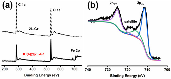
Figure 1.
Wide scan XPS spectra of 2L-Gr film (a), dotted line and IO(6)@2L-Gr sample (a), solid line. (b) Fe 2p spectrum of IO(6)@2L-Gr sample with the colored lines representing the fit of the respective peak. The 2L-Gr samples transferred on silicon wafer using PMMA and (0.04 M) ammonium persulfate as an etchant. The IO(6)@2L-Gr sample transferred on silicon wafer using PMMA and (0.22 M) iron chloride in (1 M) hydrochloric acid as an etchant.
Electrochemical impedance spectroscopy (EIS) of the charge-transfer resistance associated with the oxidation of hydrogen is performed to investigate the catalytic activity and stability of Fe2O3 NPs on CVD-graphene. The plot of the Fe2O3:CDP (1:20 gr/gr) powder-mixture electrode shows the presence of a spike (Figure 2a) approximately 25° to the X-axis, suggesting that iron oxide acted as an insulating layer, which exhibited, basically, a capacitive behavior [67]. On the other hand, the impedance curves of the 2L-Gr electrode and Fe2O3@2L-Gr electrodes exhibited semi-circle arcs. As previously demonstrated in our research group, the oxygen functional groups (OFGs) and defects present on the surface of CVD-graphene are important factors to consider in the efficiency increase of the electrodes [12,68]. However, the electrochemical enhancement of the system gradually decreased over time [12] and the influence of OFGs and defects is insignificant when compared to the impact of iron oxide (more details can be found in Supplementary Materials, Figure S2). Because neither iron oxide NPs (Figure 2a) nor CVD-graphene (Figure 2b) could hardly catalyze hydrogen oxidation, the enhanced performance was ascribed to the synergetic chemical coupling effects of the hybrid structure [69,70]. Furthermore, the stability of Fe2O3 nanoparticles on 2L-Gr was also investigated. The width of the electrode arcs for 2L-Gr, IO(2)@2L-Gr, and IO(4)@2L-Gr samples (Figure 2b,c and Figure 2d, respectively) show an increase of the electrode impedance after 24 h measurements. The stability enhancement of the CVD-graphene membranes increases proportionally to the iron ions loading along the CVD-graphene surface. Degradation of operation (for low Fe2O3 loading) can be due to CVD-graphene corrosion [71], and/or to the fact that unattached small iron oxide islands to CVD-graphene film have undergone a coalescence process (Ostwald ripening theory) and have slightly increased the charge transfer resistance. However, higher iron oxide loading (IO(6)@2L-Gr) demonstrated exceptionstability after a 24 h measurement, as seen in Figure 2e. This result showed that the Fe2O3-decorated 2L-Gr exhibited good stability over a prolonged period of time, indicating that the nanoparticles were firmly attached to the CVD-graphene substrate. The existence of covalent chemical bonding formed through oxygen-containing defect sites on the CVD-graphene surface provides an opportunity to tightly anchor iron oxide on graphene [72,73,74,75] and prevent the role of the oxygen/defect sites in the CVD-graphene electrode degradation, as reported by Lu et al. [68]. It is worth noting that water absorption on the iron oxide surface rises as relative humidity (RH) increases [76]. As a result, the electrode, which is made from a powder combination of iron oxide and CDP, absorbs a lot of water during the EIS analysis. Water adsorbs to the surface of the iron oxide, resulting in a CDP solution, and the presence of water inhibits the fuel from diffusing through the electrode. This can be the cause of the capacitive behavior. While the low amount of iron oxide NPs on the surface of graphene do not form a layer of water that causes the CDP to dissolve and blocks fuel transport.
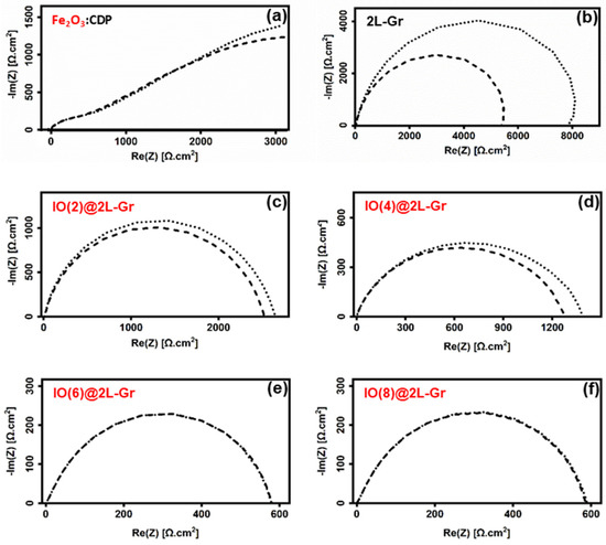
Figure 2.
Nyquist Plot of the electrode impedance for asymmetric cells: (a) (Fe2O3:CDP|CDP|Pt/C) electrode, (b) 2L-Gr sample transferred using PMMA and (0.04 M) ammonium persulfate as an etchant, (c) IO(2)@2L-Gr electrode, (d) IO(4)@2L-Gr electrode, (e) IO(6)@2L-Gr electrode, and (f) IO(8)@2L-Gr electrode, as described in (Supplementary Materials, Table S1). The electrolyte resistance was subtracted. For all electrodes dashed curves, measurement after 1 h; dotted curves, measurement after 24 h.
Electrochemical efficiency and high-performance stability of iron ions-decorated CVD-graphene material have been studied in the literature. Liu et al. [26] studied the influence of iron species types and crystalline phases on the ORR activities. Four iron/graphene composites with iron oxides (α-Fe2O3, Fe3O4) and oxyhydroxides (α-FeOOH, and α/γ-FeOOH) supported on graphene oxide (GO) have been investigated. Figure S3. shows that the α-F2O3/GO hybrid material demonstrated extraordinary and higher stability during thermogravimetric analysis (TGA) up to 300 °C. Furthermore, they reported that all four composites exhibit significantly improved ORR activities when compared to pristine GO, highlighting the ORR magic of iron species; amongst four composites investigated, the α-Fe2O3/GO exhibits the highest ORR activity in terms of onset potential and current.
2.2. Platinum-Decorated CVD-Graphene Electrode
The effect of the iron oxide addition as a co-catalyst in Pt-based electrocatalysts for SAFCs application was characterized using impedance spectroscopy under anodic conditions, as well as IV characterization and CstV measurements under fuel cell conditions.
The thickness of the 2L-Gr membranes was suitable to assess the electrochemical activity and stability of iron oxide NPs (as shown above). Since graphene material is inert and hydrophobic [77], only a trace of ALD-platinum is deposited on the surface of the CVD-graphene basal planes [14]; hence, anchoring sites on the CVD-graphene membranes are necessary to deposit ALD-platinum uniformly throughout the surface [14]. Oxygen plasma treatment was used for the surface modification of CVD-graphene. The effectiveness of the process is dependent on several factors that include the plasma treatment conditions. These conditions include the plasma power, treatment time, gas flow rate, and pressure [78]. The choice of these parameters alters the physiochemical properties of graphene, such as its electrical conductivity, mechanical strength, and chemical reactivity [79,80,81]. In our laboratory, the oxygen plasma treatment conditions were optimized by using various plasma powers and exposure times. Following a series of experiments (data not shown), the treatment of the CVD-graphene membranes with plasma generated at 100 W for 8 s resulted in surface oxidation and the creation of pits along the oxidized CVD-graphene membrane. The presence of pits facilitated a homogeneous distribution of ALD-platinum NPs on the oxidized CVD-graphene surface [14]. In order to deposit platinum on the CVD-graphene surface using ALD technology, the CVD-graphene membrane must pass through different processes (oxygen plasma treatment and CVD-graphene transfer). Multi-layer CVD-graphene films are needed for use without risk of destruction during the treatment and transfer processes. In terms of the mechanical stability of the oxidized CVD-graphene during transfer, resistance against oxidation and destruction, and taking into account electron and through-plane proton conductivity, ~5-layer CVD-graphene (5L-Gr) membranes demonstrated the optimal thickness (Supplementary Materials, Figure S1c,f). Iron oxide concentrations precipitated out of the etching solution (0.22M FeCl3/1M HCl) on 5L-Gr membranes (2.4 ± 0.3 µgFe·cm−2) were the same as those precipitated on 2L-Gr membranes (2.5 ± 0.2 µgFe·cm−2), according to ICP OES measurements. These results demonstrated that the concentration of iron oxide NPs formed on CVD-graphene after the transfer procedure is proportional to the concentration of the etching solution and not to the CVD-graphene thickness. The quality and crystallinity of the bare-graphene and Fe2O3-decorated CVD-graphene membranes were investigated by high-resolution TEM and electron beam diffraction. Approximately 60% of the CVD-graphene surface is covered with islands of amorphous material for both 5L-Gr and IO(6)@5L-Gr samples (Supplementary Materials, Figure S4), which are similar to earlier reports on CVD-graphene preparation [52,53,54]. More information regarding the iron oxide NPs distribution along the CVD-graphene layer and the level of iron oxidation can be found in (Supplementary Materials, Figures S5 and S6), respectively. The samples nomenclature hereafter follows the system PtALD-V@XL-OGrY/Z, where V is the ALD cycles number, X is the number of CVD-graphene layers (L), OGr is oxidized CVD-graphene, Y is the exposed time to plasma in seconds, and Z is the power of the used plasma in watts.
The Pt-Fe2O3-decorated oxidized CVD-graphene electrodes manufacturing is divided into two main preparation phases: the platinum-ALD deposition and iron oxide precipitated out of the etching solution. The first phase is the hybrid (Platinum|Graphene) membranes fabrication, which involves the oxidation of as-grown 5L-Gr membranes on copper foils using plasma treatment (plasma powers: 100 W/exposure time: 8 s) and then decorated with 50 and 200 Pt-ALD cycles [14], as shown in Figure S7a and Figure S7b, respectively. The second phase is iron oxide NPs precipitate out of the etching solution on the bottom side of (Platinum|Graphene) membranes during the transfer process. The electrochemical impedance spectroscopy results of platinum-decorated oxidized CVD-graphene electrodes in the absence of iron oxide (Figure 3a), and after precipitation, the iron oxide out of the etching solution (Figure 3b), are shown in Figure 4. A (~30%) lower ANR value was observed for the PtALD-200@5L-OGr8/100—Fe2O3 electrode (Figure 4a) compared to the iron-free electrode (Figure 4b). The PtALD-50@5L-OGr8/100 electrode exhibited the same trend with ~50% lower ANR values, as evident from Figure 4c,d. These preliminary results indicated that the presence of iron ions leads to a considerable improvement of the (Platinum|Graphene) electrode impedance value. The lower ANR value at the Fe2O3 nanocomposite-coated PtALD@5L-OGr8/100 electrode can be attributed to the fast electron transfer that arrives from the synergistic electrical conductivity afforded by PtALD NPs/film, Fe2O3, and the CVD-graphene membrane [82,83]. These outstanding properties of the CVD-graphene materials, along with the high catalytic activity of the composite catalyst (platinum and Fe2O3), make them suitable for electrocatalytic applications. PtALD-decorated oxidized CVD-graphene cells were, then, characterized using IV characterization and CstV measurements under fuel cell conditions.
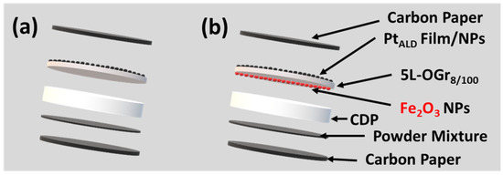
Figure 3.
A cartoon showing the PtALD-V@5L-OGr8/100 cells fabrication: The PtALD-V@5L-OGr8/100 films transferred onto the CDP surface using PMMA and (a) ammonium persulfate (0.04 M) (b) hydrochloric solution (1 M) of ferric chloride (0.22 M) as an etchant.
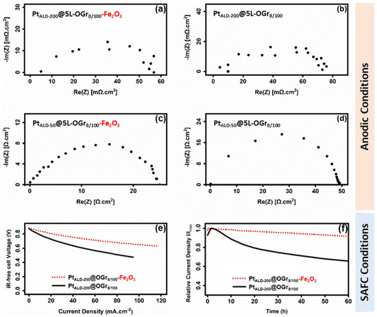
Figure 4.
Nyquist Plot of the electrodes impedance of the PtALD@5L-OGr8/100 electrodes transferred using PMMA and: (a,c) hydrochloric solution (1 M) of ferric chloride (0.22 M) (b,d) ammonium persulfate (0.04 M) as an etchant. All samples have been pre-treated with oxygen plasma generated at 100 W for 8 s, then decorated with 200 ALD cycles (a,b), and 50 cycles (c,d). The electrolyte resistance was subtracted. IV curves of the PtALD-200@5L-OGr8/100 cathodes transferred using PMMA with (0.04 M) ammonium persulfate (solid line) and (0.22 M) iron chloride in (1 M) HCl (dotted line) are shown in (e). The voltage has been corrected for the ohmic losses determined with impedance spectroscopy. The current density at 0.35 V of the PtALD-200@5L-OGr8/100 cathodes transferred using PMMA with (0.04 M) ammonium persulfate (solid line) and (0.22) M iron chloride in (1 M) HCl (dotted line) are shown in (f). ICP OES measurements: (59 ± 2 µgPt·cm−2) in (a,b,e,f), (13.8 ± 1 µgPt·cm−2) in (c,d), (2.4 ± 0.3 µgFe·cm−2) in (a,c) and in dotted line in (e,f). (a) Reproduced with permission [14].
Based on previous results, PtALD-200@5L-OGr8/100 cathodes demonstrated the highest electrode activity among electrodes based on the same oxidized CVD-graphene membranes, but with varying platinum loading [14]. The IV curves of the PtALD-200@5L-OGr8/100 (59 ± 2 µgPt·cm−2) cathodes transferred by ammonium persulfate (Figure 3a) and iron chloride (Figure 4e—dotted line) and PtALD-200@5L-OGr8/100 cathode (Figure 4e—solid line), respectively. The performance activity of PtALD-200@5L-OGr8/100 catalysts is improved further when the Fe2O3 nanoparticles are precipitated on the oxidized CVD-graphene surface during the electrode preparation, as shown in Figure 4e. With increasing current density, the voltage output of the PtALD-200@5L-OGr8/100-MEA drops faster than that of the PtALD-200@5L-OGr8/100—Fe2O3-MEA. A positive effect of Fe2O3 nanoparticles presence on the performance activity of PtALD-200@5L-OGr8/100 hybrid cathode was observed. These results agree with the EIS shown in Figure 4. The ORR specific activity of (Platinum|Iron) alloys [84,85,86,87,88,89,90,91,92] and (Platinum|Iron oxide) alloys [26,51,93] has been investigated. Alloying the iron (oxide) with platinum [94] results in an enhancement of the ORR activity of platinum, in agreement with the different considerations (geometric factors) [95], dissolution of the more oxidizable alloying component [96], changing in the surface structure or electronic factors [97], the formation of a platinum skin [98,99], or the interplay between the electronic and geometric factors [100]). Although the effect of iron (oxide) on improving the effectiveness of platinum in ORR has been demonstrated and explained in detail in the literature, it is still a controversial topic for the new electrode design in this study. The (Platinum|Fe2O3) electrocatalysts used in this study were fabricated differently than the (Platinum|Fe2O3) alloys described in the literature [26,51,84,85,86,87,88,89,90,91,92,93,94,95,96,97,98,99,100]. This new design is based on a simple structure where the (Platinum|Fe2O3) electrocatalysts were deposited separately on both sides of oxidized CVD-graphene substrate (not in direct contact between the platinum and the iron (oxide)); while the iron oxide precipitated out of the etching solution on the bottom side, the surface of the oxidized CVD-graphene substrate was decorated with platinum. By separating the two electrocatalysts (platinum and the Fe2O3) with a thin CVD-Gr membrane, this new hybrid electrode can be used in ambient pressure XPS experiments to gain a better understanding of the electrochemical reaction process [101] for SACFs and beyond. More research on the effect of iron oxide in improving the activity of the PtALD-200@5L-Gr8/100 electrode is now being undertaken. Apart from activity, the performance of the PtALD-200@5L-OGr8/100 cathode exhibited a higher stability in the presence of Fe2O3 NPs, as observed in the constant voltage measurement at 0.35 V for 60 h, as shown in Figure 4f. During the first hour, the current density of the PtALD-200@5L-OGr8/100—Fe2O3-MEA increases. We attribute the observed increasing current density to the removal of the PMMA-residues and/or to the sintering of the electrolyte layer [24,25]. After the initial increase period, the current density of the electrode shows quasi-steady state with a slight decay by just 0.13% h−1, as shown in Figure 4f—dotted line. The same trend was observed for PtALD-200@5L-OGr8/100-MEA (Figure 4f—solid line).
The current density increases within the first 2 h. However, the absence of iron oxide NPs leads to a rapid reduction of the current density by 1.4% h−1 within the first 8 h, followed by a reduction of the degradation rate to 0.23% h−1 between 50–60 h, as shown in Figure 4f—solid line. The high stability of the PtALD-200@5L-OGr8/100—Fe2O3 cathode might be caused by the composition and/or structure preventing platinum sites from segregating, dissolving, phosphate-associated catalyst poisoning, and forming platinum oxides during the reaction [50,51,102,103,104,105]. However, at this point the exact mechanism is unclear. This study unveils the diverse ORR behaviors of iron species supported on CVD-graphene, and explores the benchmark of their catalytic performance towards ORR. It provides useful insights into the Fe/FeXOY-enabled high ORR activity to guide the design of efficient transition metal-based ORR electrocatalysts.
3. Materials and Methods
Unless otherwise specified, reagents were used as received without further purification.
3.1. CVD-Graphene Preparation
Mono-layer CVD-graphene films are produced using a rapid thermal processing cold wall reactor (Moorfield nanoCVD, Knutsford, Cheshire, UK). The process involves heating the Copper foil (Alfa Aesar, 99.999%, Kandel, Germany) in a six-stage process including: (I) The copper foil is subjected to a process of heating at a rate of 9 °C/s in a vacuum environment of approximately 3 Torr. The heating is carried out up to a temperature of 930 °C, with an atmosphere containing Ar (198 SCCM) and H2 (2 SCCM) gases. (II) To minimize oxides on the copper surface and promote grain formation, the copper substrate is annealed for 2 min under the same conditions as in stage (I). The temperature of the heating stage (III) is then ramped up from 930 °C to 1030 °C for over 5 min, followed by (IV) another annealing stage for 30 min under the same conditions as in stage (I). A combination of Ar/CH4/H2 gas is then utilized for monolayer CVD-graphene growth (V), with Ar pressure 1.04 Torr (flow 40 SCCM), H2 pressure 0.21 Torr (flow 8 SCCM), and CH4 pressure 0.05 Torr (flow 2 SCCM) while the chamber pressure is kept at 1.3 Torr for 30 min, and (VI) cooling the (Graphene|Copper) foil to room temperature over 10 min. By adjusting the working pressure during the growth step, high quality single-layer and multi-layer CVD-graphene can be produced.
3.2. CVD-Graphene Transfer
In this work, we followed the CVD-graphene transfer process reported by Hatahet et al. [14,106]. Briefly, as-grown CVD-graphene films were transferred onto various substrates using wet chemical etching of the Cu foils in solutions containing iron (III) chloride (VWR, 99–102%) in hydrochloride acid (HCl, Sigma-Aldrich, 37%, Taufkirchen, Germany) or ammonium persulfate (Sigma-Aldrich, ≥98.0%, Taufkirchen, Germany). Prior to etching, the surface of the (Graphene|Copper) was coated with 200 µL of PMMA dissolved in chlorobenzene [107]. The PMMA was then allowed to air-dry overnight. The bottom side of the copper foil was floated on a nitric acid solution to etch the bottom side CVD-graphene. The (PMMA|Graphene|Copper) film was allowed to float on the etchant’s surface, carried by surface tension force for 8 h. The CVD-graphene layer was then transferred onto the desired substrates and dried with a nitrogen stream. Finally, the PMMA layer was dissolved with acetone, and the CVD-graphene was annealed for 12 h at 120 °C under high vacuum.
3.3. Oxygen Plasma Treatment
A radio frequency (RF) plasma system (Junior Plasma System, Europlasma NV, Oudenaarde, Belgium) equipped with a 300-W kHz generator was used to oxidize the CVD-graphene surface. The vacuum chamber was pumped down to 120 mTorr throughout the treatment procedure. When the base pressure was established, a mass flow controller (MFC) delivered 20 SCCM of oxygen gas into the chamber during a 180-s stabilization phase. After the stabilization of the pressure, the oxygen plasma was generated by the radio frequency (RF:13.56 MHz) power source. At a working pressure of 180–195 mTorr, the CVD-graphene samples were exposed to plasma. Finally, all samples were placed in a nitrogen environment until further treatment or measurement.
3.4. Catalyst Deposition
Platinum deposition on oxidized CVD-graphene substrates was performed with a home-built ALD device that provides thermal-enhanced ALD configurations. The samples were placed on a stainless-steel sample holder, which was then loaded into the ALD reactor and positioned in the center of the reactor. In the reactor chamber, the temperature of the substrate maintained at 275 °C. After that, the reactor was evacuated and thermally equilibrated overnight. Trimethyl (methylcyclopentadienyl) platinum (Pt(MeCp)Me3, Strem Chemicals, 99%, Newburyport, MA, USA) was used as the platinum precursor, and oxygen as the co-reactant. A Pt(MeCp)Me3 precursor was loaded to the stainless-steel bubbler (Swagelok) in a glovebox and then connected directly to the system without being exposed to the air. To provide enough vapor pressure, the temperature of the platinum precursor in the bubbler was kept constant at 50 °C. The platinum precursor vapor was carried by heated nitrogen into the ALD chamber, through a delivery line which was heated to 130 °C. At a flow rate of 150 SCCM, ultra-high purity nitrogen (99.9995%) was utilized as a carrier gas and as a flush gas to remove unreacted precursors and byproducts during the reaction. With a flow rate of 60 SCCM during a continuous flow, the oxygen source was pulsed into the reactor through a needle valve and a solenoid valve. A static exposure mode was applied during both ALD half-cycles. The Pt(MeCp)Me3 precursor was pulsed for 1 s, and the valves to the pumping system remained closed for an additional 10 s to extend the precursor’s dwell time, resulting in an 11 s total exposure time. N2 gas purge was then conducted for 80 s to fully eliminate the reactant gases. The system was then evacuated for 40 s, followed by a 1 s dose of O2. Another purge with N2 gas for 80 s and evacuation for 40 s were subsequently carried out.
3.5. Electrochemical Cell Characterization
3.5.1. Preparation of Membrane-Electrode Assembly (MEA)
The solid acid electrolyte (CDP) was synthesized by dissolving stoichiometric quantities (molar ratio 1:2) of Cs2CO3 (Alfa Aesar, 99.99%, Kandel, Germany) and phosphoric acid (H3PO4, Carl Roth, ≥85%, Karlsruhe, Germany) in methanol (Carl Roth, ≥99%, Karlsruhe, Germany) separately. The two solutions were combined and stirred for 1 h at 1500 (r.p.m). The CDP powder was filtered, rinsed with methanol, and dried at 80 °C. The metal-decorated CVD-graphene cells were structured in two steps. The first step involved forming identical anodes with a Pt loading of 7.7 mg·cm−2. The anodes were formed using a powder-mixture preparation technique described by Uda and Haile [108], which involved mixing and grinding CsH2PO4, Pt-black (Sigma-Aldrich, 99.9%, fuel cell grade, Taufkirchen, Germany), platinum on carbon (Alfa Aesar, HiSPEC 4100, Kandel, Germany), and naphthalene (Alfa Aesar, 99+%, Kandel, Germany) in a 3:3:1:0.5 mass ratio. Carbon paper discs (Toray TGP-H-120) and CDP membranes were then pressed uniaxially in a hydraulic press (Atlas Auto 15T, Specac Ltd., London, UK) to the anode, maintaining 125 and 200 MPa for 20 min for the 2 cm diameter MEAs for fuel cell measurements and for the 1 cm MEAs for measurements under anodic conditions, respectively, as shown in as shown in Figure 5a. These anodes were used for all cells presented in this work.
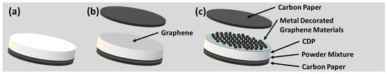
Figure 5.
A cartoon showing the CVD-graphene/metal-decorated CVD-graphene cell fabrication: (a) first step of a membrane electrode assembly and (b) CVD-graphene transfer, and (c) second step for metal-decorated oxidized multi-layer CVD-graphene.
The second step commenced with the wet chemical etching of copper foils to transfer either CVD-graphene (Figure 5b) or metal-decorated CVD-graphene materials (Figure 5c) [14]. After removing the etchant, an additional crucial step involved the gentle pouring of 250 mL of acetone (Merck, ≥99.8%) into water to prevent damage or dissolution of the CsH2PO4 surface after transferring the wet CVD-graphene/metal-decorated (oxidized) CVD-graphene films. The pellets (Figure 5b,c) were then placed under vacuum (~6 Torr) for 48 h to enhance adhesion between CVD-graphene and the CsH2PO4 surface. Finally, the PMMA layer was removed using pure acetone, followed by a 12-h vacuum annealing procedure at 120 °C.
3.5.2. Electrochemical Testing
The electron transfer kinetics of hydrogen electrooxidation were studied by electrochemical impedance spectroscopy (EIS) measurements (Biologic, VSP300, Seyssinet-Pariset, France). Stainless steel porous meshes (GKN Sinter Metals Filter GmbH, Radevormwald, Germany) were used as gas diffusion layers. AC impedance measurements were performed at frequencies ranging from 10 mHz to 7 MHz with a voltage amplitude of 10 mV. The experiments were conducted at a temperature of 240 °C in a humidified H2 atmosphere (p(H2O) = 0.4 atm). The inlet gases were flowed through a Q-water bubbler held at 80 °C at a rate of 30 SCCM, while argon gas was flown at 120 SCCM to prevent cell condensation during heating and cooling. The fuel-cell measurements were conducted at a temperature of 240 °C with pure oxygen and hydrogen flow rates of 50 SCCM each at a dew point of 80 °C. Current-voltage (IV) characterization measurements were taken by scanning cell potential at 10 mV·s−1 from the open circuit voltage to 0 V using the same equipment.
3.6. Characterization Methods
Atomic force microscopy (Bruker Dimension Icon AFM, Billerica, MA, USA) using OTESPA-R3 cantilevers in tapping mode was used to characterize the surface morphology of CVD-graphene samples on SiO2/Si wafers with a resolution of 1024 × 1024 pixels. The obtained data was plane-corrected using SPIP 6.7.3 software. Scanning electron microscope (SEM) imaging at 2 kV using the in-lens detector was also performed using an Ultra 55 SEM by Carl Zeiss Ltd. (Cambourne, UK). High-resolution transmission electron microscopy (HRTEM), selected area electron diffraction (SAED), scanning TEM (STEM), and energy-dispersive X-ray spectroscopy (EDS) were performed with a Cs-corrected Titan3 G2 60–300 microscope equipped with X-FEG electron gun and Super-X detector. The TEM was operated at an acceleration voltage of 80 kV and a probe-forming aperture of 25 mrad. TEM samples were prepared by free-PMMA transfer of the ~5-layer CVD-graphene samples (as described in Section 3.2, without PMMA spin-coating step) onto a holey amorphous carbon-coated copper grid (mesh size = 400). Raman spectra were recorded using a 532 nm laser and a Horiba LabRam confocal spectrometer with a resolution of 1.3 cm−1 (600 lines/mm grid to record both the 2D-peak and the G-peak simultaneously). X-ray photoelectron spectroscopy (XPS) analyses were carried out on a Kratos Axis Ultra (Kratos Analytical, Ltd., Manchester, United Kingdom) with a monochromatized Al excitation source at 150 W (15 kV, 10 mA, with a pass energy of 40 eV), collecting surface spectra over a range of 0–1200 eV. Inductively coupled plasma optical emission spectroscopy (SPECTRO Ciros Vision, Kleve-Germany, ICP OES) was used to determine the mass fraction of platinum and iron on CVD-graphene samples. The samples were digested in a 28 vol% acid solution with a 6:1 volume ratio of HCl:HNO3 in Millipore water for 30 min, followed by microwave (MLS Mikrowellen Laborsysteme, microPREP) digestion for 40 min at 235 °C and another digestion step for 24 h at RT. The use of analytical techniques like ICP OES provided more precise and accurate results for analyte concentration determination [109,110,111].
4. Conclusions
In summary, the study explored the functionalization of CVD-graphene with iron oxide nanoparticles to improve its electrocatalytic properties. The Fe2O3 functionalization density was controlled by adjusting the iron (III) chloride concentration in the etching solution. The Fe2O3-decorated CVD-graphene composite exhibited better hydrogen electrooxidation performance (ANR of ~600 Ω·cm−2) and superior stability in comparison with bare-graphene samples (ANR of ~5800 Ω·cm−2). (Fe2O3|Graphene) is an attractive non-Pt electrocatalyst due to its high activity, stability, and synergistic effect between CVD-graphene and iron oxide. The development of (Fe2O3|Graphene) electrocatalysts for fuel cells could potentially reduce the reliance on Pt and improve the energy conversion efficiency.
Benefiting from the combined advantages of CVD-graphene and iron oxide nanoparticles, these Fe2O3 NPs showed superior platinum utilization in the electrodes. Electrochemical impedance measurements in humidified hydrogen at 240 °C for (Fe2O3|Graphene|Platinum) electrodes show ANR of ~0.06 Ω·cm−2 for a platinum loading of ~60 µgPt·cm−2 and Fe2O3 loading of ~2.4 µgFe·cm−2, resulting in an outstanding mass normalized activity of almost 280 S·mg·Pt−1, exceeding even state-of-the-art electrodes. This ANR value is ~30% lower than the charge transfer resistance of the same electrode composition in the absence of Fe2O3 NPs.
The utilization and electrochemical stability of (Platinum|Graphene) cathodes were enhanced by the presence of Fe2O3 nanoparticles. The relative current density (I/Imax) was increased from 0.66 to 0.92 on the PtALD-200@5L-OGr8/100 cathode in the presence of Fe2O3 NPs after 60 h of constant voltage measurement at 0.35 V. These findings demonstrate that iron oxide nanoparticles are an excellent co-catalyst for synthesizing hybrid (Platinum|Graphene) electrocatalysts, which opens a reliable path to the discovery of an advanced concept in designing new catalysts that can replace the traditional catalytic structure and motivate further research in the SACFs field and beyond. Further research is needed to optimize the synthesis and catalytic performance of Fe2O3|Graphene and to understand the underlying mechanism of ORR on Fe2O3|Graphene. Understanding the electrochemical reaction process of the electrode is fundamentally important for developing highly efficient and selective electrocatalysts. The (platinum|Fe2O3) electrocatalyst used in this study was fabricated in a new design, where the (platinum|Fe2O3) electrocatalysts were deposited separately on both sides of the oxidized CVD-graphene substrate. This new hybrid electrode design can be used in ambient pressure XPS experiments to gain a better understanding of the electrochemical reaction process.
Supplementary Materials
The following supporting information can be downloaded at: https://www.mdpi.com/article/10.3390/catal13081154/s1, Figure S1: AFM images of as-grown (a) monolayer CVD-graphene, (b) 2L-Gr, (c) 5L-Gr films. Raman spectrum with a 532 nm excitation laser wavelength of (d) monolayer CVD-graphene, (e) 2L-Gr, (f) 5L-Gr films. All CVD-graphene samples transferred on silicon wafer using PMMA and (0.04 M) ammonium persulfate as an etchant; Table S1: Atomic Composition at the surface of the decorated CVD-graphene samples on Si-wafer substrates with different etchants concentrations as determined by XPS with the corresponding Fe mass fraction measured by ICP OES; Figure S2. Raman spectra of pristine 2L-Gr and Fe2O3-decorated 2L-Gr samples with different concentrations as described in Table S1; Figure S3. TGA curves of α-Fe2O3, Fe3O4, α-FeOOH, and α/γ-FeOOH-decorated graphene oxide (GO). TGA was performed under air atmosphere. GO is Graphene Oxide; Figure S4. TEM micrographs of 5L-Gr sample transferred using ammonium persulfate as an etchant, low magnification (a), high magnification (c). TEM micrographs of IO(6)@5L-Gr sample, low magnification (b), high magnification (d); Figure S5. (a) HAADF micrograph of a section of a IO(6)@5L-Gr membrane. (b-e) Elemental mapping images of IO(6)@5L-Gr sample. (f) HAADF micrograph of a section of a 5L-Gr membrane. (g–j) Elemental mapping images of 5L-Gr sample. Scale bar: (a–j) 70 nm; Figure S6. SAED pattern of IO(6)@5L-Gr sample; Figure S7. SEM images of 5L-OGr8/100 sample after (a) 50 PtALD cycles and (b) 200 PtALD cycles. All CVD-graphene samples were first oxidized on copper before being deposited with platinum via ALD. Then the Platinum@oxidized CVD-graphene films were transferred on pre-cleaned silicon wafers using PMMA and (0.04 M) ammonium persulfate as an etchant. References [12,14,26,38,44,52,53,54,68,82,107] are cited in the Supplementary Materials.
Author Contributions
M.H.H. conducted all the experiments except the TEM and SAED measurements, which were done by H.B. Writing—M.H.H. wrote the first draft of the paper. H.B., A.L., M.W. and B.A. contributed to the data interpretation, the discussion, and the revision of the paper; TEM process supervision, A.L.; project administration, B.A. All authors have read and agreed to the published version of the manuscript.
Funding
This research received no external funding.
Data Availability Statement
The data that support the findings of this study are available from the corresponding author upon reasonable request.
Acknowledgments
The authors thank Nadja Schönherr and Andrea Prager for ICP OES measurements, and the XPS measurements, respectively. M.H.H. is grateful to the German Foreign Ministry and for a DAAD scholarship. The authors are indebted to Felix Lohmann, Jan Griebel, and Ulrike Helmstedt for general support and interesting discussion.
Conflicts of Interest
The authors declare no conflict of interest.
References
- Karim, N.A.; Kamarudin, S.K. An Overview on Non-Platinum Cathode Catalysts for Direct Methanol Fuel Cell. Appl. Energy 2013, 103, 212–220. [Google Scholar] [CrossRef]
- Andújar, J.M.; Segura, F. Fuel Cells: History and Updating. A Walk along Two Centuries. Renew. Sustain. Energy Rev. 2009, 13, 2309–2322. [Google Scholar] [CrossRef]
- Ahmad, M.M.; Kamarudin, S.K.; Daud, W.R.W.; Yaakub, Z. High Power Passive ΜDMFC with Low Catalyst Loading for Small Power Generation. Energy Convers. Manag. 2010, 51, 821–825. [Google Scholar] [CrossRef]
- Basri, S.; Kamarudin, S.K. Process System Engineering in Direct Methanol Fuel Cell. Int. J. Hydrogen Energy 2011, 36, 6219–6236. [Google Scholar] [CrossRef]
- Dwivedi, K.A.; Huang, S.-J.; Wang, C.-T. Integration of Various Technology-Based Approaches for Enhancing the Performance of Microbial Fuel Cell Technology: A Review. Chemosphere 2022, 287, 132248. [Google Scholar] [CrossRef] [PubMed]
- Jacobson, M.Z.; Colella, W.G.; Golden, D.M. Cleaning the Air and Improving Health with Hydrogen Fuel-Cell Vehicles. Science 2005, 308, 1901–1905. [Google Scholar] [CrossRef]
- Haile, S.M.; Boysen, D.A.; Chisholm, C.R.I.; Merle, R.B. Solid Acids as Fuel Cell Electrolytes. Nature 2001, 410, 910–913. [Google Scholar] [CrossRef]
- Sanghvi, S.; Haile, S.M. Crystal Structure, Conductivity, and Phase Stability of Cs3(H1.5PO4)2 under Controlled Humidity. Solid State Ion. 2020, 349, 115291. [Google Scholar] [CrossRef]
- Navarrete, L.; Andrio, A.; Escolástico, S.; Moya, S.; Compañ, V.; Serra, J.M. Protonic Conduction of Partially-Substituted CsH2PO4 and the Applicability in Electrochemical Devices. Membranes 2019, 9, 49. [Google Scholar] [CrossRef] [PubMed]
- Wagner, M.; Dreßler, C.; Lohmann-Richters, F.P.; Hanus, K.; Sebastiani, D.; Varga, A.; Abel, B. Mechanism of Ion Conductivity through Polymer-Stabilized CsH2PO4 Nanoparticular Layers from Experiment and Theory. J. Mater. Chem. A 2019, 7, 27367–27376. [Google Scholar] [CrossRef]
- Lohmann-Richters, F.P.; Odenwald, C.; Kickelbick, G.; Abel, B.; Varga, Á. Facile and Scalable Synthesis of Sub-Micrometer Electrolyte Particles for Solid Acid Fuel Cells. RSC Adv. 2018, 8, 21806–21815. [Google Scholar] [CrossRef] [PubMed]
- Naumov, O.; Naumov, S.; Abel, B.; Varga, A. The Stability Limits of Highly Active Nitrogen Doped Carbon ORR Nano-Catalysts: A Mechanistic Study of Degradation Reactions. Nanoscale 2018, 10, 6724–6733. [Google Scholar] [CrossRef]
- Afroze, S.; Reza, M.S.; Somalu, M.R.; Azad, A.K. Super–Protonic Conductors for Solid Acid Fuel Cells (SAFCs): A Review. Eurasian J. Phys. Funct. Mater. 2023, 7, 6–37. [Google Scholar] [CrossRef]
- Hatahet, M.H.; Wagner, M.; Prager, A.; Helmstedt, U.; Abel, B. Functionalized and Platinum-Decorated Multi-Layer Oxidized Graphene as a Proton, and Electron Conducting Separator in Solid Acid Fuel Cells. Catalysts 2021, 11, 947. [Google Scholar] [CrossRef]
- Papandrew, A.B.; Chisholm, C.R.I.; Elgammal, R.A.; Özer, M.M.; Zecevic, S.K. Advanced Electrodes for Solid Acid Fuel Cells by Platinum Deposition on CsH2PO4. Chem. Mater. 2011, 23, 1659–1667. [Google Scholar] [CrossRef]
- Uda, T. Thermodynamic, Thermomechanical, and Electrochemical Evaluation of CsHSO4. Solid State Ion. 2005, 176, 127–133. [Google Scholar] [CrossRef]
- Debe, M.K.; Schmoeckel, A.K.; Vernstrom, G.D.; Atanasoski, R. High Voltage Stability of Nanostructured Thin Film Catalysts for PEM Fuel Cells. J. Power Source 2006, 161, 1002–1011. [Google Scholar] [CrossRef]
- Gasteiger, H.A.; Marković, N.M. Just a Dream—Or Future Reality? Science 2009, 324, 48–49. [Google Scholar] [CrossRef]
- Strasser, P.; Koh, S.; Anniyev, T.; Greeley, J.; More, K.; Yu, C.; Liu, Z.; Kaya, S.; Nordlund, D.; Ogasawara, H.; et al. Lattice-Strain Control of the Activity in Dealloyed Core–Shell Fuel Cell Catalysts. Nat. Chem. 2010, 2, 454–460. [Google Scholar] [CrossRef]
- Wang, C.; van der Vliet, D.; More, K.L.; Zaluzec, N.J.; Peng, S.; Sun, S.; Daimon, H.; Wang, G.; Greeley, J.; Pearson, J.; et al. Multimetallic Au/FePt3 Nanoparticles as Highly Durable Electrocatalyst. Nano Lett. 2011, 11, 919–926. [Google Scholar] [CrossRef]
- Wu, J.; Zhang, J.; Peng, Z.; Yang, S.; Wagner, F.T.; Yang, H. Truncated Octahedral Pt 3 Ni Oxygen Reduction Reaction Electrocatalysts. J. Am. Chem. Soc. 2010, 132, 4984–4985. [Google Scholar] [CrossRef] [PubMed]
- Zhou, W.-P.; Sasaki, K.; Su, D.; Zhu, Y.; Wang, J.X.; Adzic, R.R. Gram-Scale-Synthesized Pd2 Co-Supported Pt Monolayer Electrocatalysts for Oxygen Reduction Reaction. J. Phys. Chem. C 2010, 114, 8950–8957. [Google Scholar] [CrossRef]
- Fang, B.; Chaudhari, N.K.; Kim, M.-S.; Kim, J.H.; Yu, J.-S. Homogeneous Deposition of Platinum Nanoparticles on Carbon Black for Proton Exchange Membrane Fuel Cell. J. Am. Chem. Soc. 2009, 131, 15330–15338. [Google Scholar] [CrossRef] [PubMed]
- Tennyson, W.D.; Tian, M.; Papandrew, A.B.; Rouleau, C.M.; Puretzky, A.A.; Sneed, B.T.; More, K.L.; Veith, G.M.; Duscher, G.; Zawodzinski, T.A.; et al. Bottom up Synthesis of Boron-Doped Graphene for Stable Intermediate Temperature Fuel Cell Electrodes. Carbon 2017, 123, 605–615. [Google Scholar] [CrossRef]
- Lohmann, F.P.; Schulze, P.S.C.; Wagner, M.; Naumov, O.; Lotnyk, A.; Abel, B.; Varga, Á. The next Generation Solid Acid Fuel Cell Electrodes: Stable, High Performance with Minimized Catalyst Loading. J. Mater. Chem. A 2017, 5, 15021–15025. [Google Scholar] [CrossRef]
- Liu, X.; Hu, W. Iron Oxide/Oxyhydroxide Decorated Graphene Oxides for Oxygen Reduction Reaction Catalysis: A Comparison Study. RSC Adv. 2016, 6, 29848–29854. [Google Scholar] [CrossRef]
- Wang, K.; Chen, H.; Zhang, X.; Tong, Y.; Song, S.; Tsiakaras, P.; Wang, Y. Iron Oxide@graphitic Carbon Core-Shell Nanoparticles Embedded in Ordered Mesoporous N-Doped Carbon Matrix as an Efficient Cathode Catalyst for PEMFC. Appl. Catal. B Environ. 2020, 264, 118468. [Google Scholar] [CrossRef]
- Fan, Z.; Li, J.; Yang, W.; Fu, Q.; Sun, K.; Song, Y.-C.; Wei, Z.; Liao, Q.; Zhu, X. Green and Facile Synthesis of Iron Oxide Nanoparticle-Embedded N-Doped Biocarbon as an Efficient Oxygen Reduction Electrocatalyst for Microbial Fuel Cells. Chem. Eng. J. 2020, 385, 123393. [Google Scholar] [CrossRef]
- Ayyubov, I.; Tálas, E.; Berghian-Grosan, C.; Románszki, L.; Borbáth, I.; Pászti, Z.; Szegedi, Á.; Mihály, J.; Vulcu, A.; Tompos, A. Nitrogen Doped Carbonaceous Materials as Platinum Free Cathode Electrocatalysts for Oxygen Reduction Reaction (ORR). React. Kinet. Mech. Catal. 2023, 136, 125–147. [Google Scholar] [CrossRef]
- Sudarsono, W.; Tan, S.Y.; Wong, W.Y.; Omar, F.S.; Ramya, K.; Mehmood, S.; Numan, A.; Walvekar, R.; Khalid, M. From Catalyst Structure Design to Electrode Fabrication of Platinum-Free Electrocatalysts in Proton Exchange Membrane Fuel Cells: A Review. J. Ind. Eng. Chem. 2023, 122, 1–26. [Google Scholar] [CrossRef]
- Chen, X.; Yu, L.; Wang, S.; Deng, D.; Bao, X. Highly Active and Stable Single Iron Site Confined in Graphene Nanosheets for Oxygen Reduction Reaction. Nano Energy 2017, 32, 353–358. [Google Scholar] [CrossRef]
- Ferrandon, M.S.; Park, J.H.; Wang, X.; Coleman, E.; Jeremy Kropf, A.; Myers, D.J. Enhancing the Activity of Fe-N-C Oxygen Reduction Reaction Electrocatalysts by High-Throughput Exploration of Synthesis Parameters. Electrochim. Acta 2023, 441, 141850. [Google Scholar] [CrossRef]
- Nielander, A.C. Deploying Cerium to Stabilize Iron-Nitrogen-Carbon Catalysts during the ORR. Chem. Catal. 2023, 3, 100566. [Google Scholar] [CrossRef]
- Villanueva-Martínez, N.I.; Alegre, C.; Martínez-Visús, I.; Lázaro, M.J. Bifunctional Oxygen Electrocatalysts Based on Non-Critical Raw Materials: Carbon Nanostructures and Iron-Doped Manganese Oxide Nanowires. Catal. Today 2023, 420, 114083. [Google Scholar] [CrossRef]
- Youn, D.H.; Jang, J.-W.; Kim, J.Y.; Jang, J.S.; Choi, S.H.; Lee, J.S. Fabrication of Graphene-Based Electrode in Less than a Minute through Hybrid Microwave Annealing. Sci. Rep. 2015, 4, 5492. [Google Scholar] [CrossRef]
- Smaisim, G.F.; Abed, A.M.; Al-Madhhachi, H.; Hadrawi, S.K.; Al-Khateeb, H.M.M.; Kianfar, E. Graphene-Based Important Carbon Structures and Nanomaterials for Energy Storage Applications as Chemical Capacitors and Supercapacitor Electrodes: A Review. Bionanoscience 2023, 13, 219–248. [Google Scholar] [CrossRef]
- Jehad, A.K.; Fidan, M.; Ünverdi, Ö.; Çelebi, C. CVD Graphene/SiC UV Photodetector with Enhanced Spectral Responsivity and Response Speed. Sens. Actuators A Phys. 2023, 355, 114309. [Google Scholar] [CrossRef]
- Li, P.; Jing, G.; Zhang, B.; Sando, S.; Cui, T. Single-Crystalline Monolayer and Multilayer Graphene Nano Switches. Appl. Phys. Lett. 2014, 104, 113110. [Google Scholar] [CrossRef]
- Bahri, M.; Gebre, S.H.; Elaguech, M.A.; Dajan, F.T.; Sendeku, M.G.; Tlili, C.; Wang, D. Recent Advances in Chemical Vapour Deposition Techniques for Graphene-Based Nanoarchitectures: From Synthesis to Contemporary Applications. Coord. Chem. Rev. 2023, 475, 214910. [Google Scholar] [CrossRef]
- Varshney, V.; Patnaik, S.S.; Roy, A.K.; Froudakis, G.; Farmer, B.L. Modeling of Thermal Transport in Pillared-Graphene Architectures. ACS Nano 2010, 4, 1153–1161. [Google Scholar] [CrossRef]
- Al Busaidi, H.; Suhail, A.; Jenkins, D.; Pan, G. Developed Graphene/Si Schottky Junction Solar Cells Based on the Top-Window Structure. Carbon Trends 2023, 10, 100247. [Google Scholar] [CrossRef]
- Hwang, J.; Lee, J.; Ryu, S.; Woo, Y.S. Role of Graphene towards Long-Term Stability of Flexible Heaters Made of Graphene-Coated Silver Nanowire Networks under Repeated Deformation. J. Mater. Sci. Mater. Electron. 2023, 34, 130. [Google Scholar] [CrossRef]
- Aiswaria, P.; Mohamed, N.S.; Singaravelu, D.L.; Brindhadevi, K.; Pugazhendhi, A. A Review on Graphene/Graphene Oxide Supported Electrodes for Microbial Fuel Cell Applications: Challenges and Prospects. Chemosphere 2022, 296, 133983. [Google Scholar] [CrossRef]
- Fisichella, G.; Di Franco, S.; Fiorenza, P.; Lo Nigro, R.; Roccaforte, F.; Tudisco, C.; Condorelli, G.G.; Piluso, N.; Spartà, N.; Lo Verso, S.; et al. Micro- and Nanoscale Electrical Characterization of Large-Area Graphene Transferred to Functional Substrates. Beilstein J. Nanotechnol. 2013, 4, 234–242. [Google Scholar] [CrossRef]
- Zhou, Y.; Wang, J.; He, P.; Chen, S.; Chen, Z.; Zang, Y.; Li, Y.; Duan, Y. ALD-Assisted Graphene Functionalization for Advanced Applications. J. Electron. Mater. 2022, 51, 2766–2785. [Google Scholar] [CrossRef]
- Wang, X.; Zhang, Y.; Li, J.; Liu, G.; Gao, M.; Ren, S.; Liu, B.; Zhang, L.; Han, G.; Yu, J.; et al. Platinum Cluster/Carbon Quantum Dots Derived Graphene Heterostructured Carbon Nanofibers for Efficient and Durable Solar-Driven Electrochemical Hydrogen Evolution. Small Methods 2022, 6, 2101470. [Google Scholar] [CrossRef]
- Bouwman, P.J.; Dmowski, W.; Stanley, J.; Cotten, G.B.; Swider-Lyons, K.E. Platinum-Iron Phosphate Electrocatalysts for Oxygen Reduction in PEMFCs. J. Electrochem. Soc. 2004, 151, A1989. [Google Scholar] [CrossRef]
- Duchesne, P.N.; Chen, G.; Zheng, N.; Zhang, P. Local Structure, Electronic Behavior, and Electrocatalytic Reactivity of CO-Reduced Platinum–Iron Oxide Nanoparticles. J. Phys. Chem. C 2013, 117, 26324–26333. [Google Scholar] [CrossRef]
- Yu, B.; Liu, Q.; Nichols, F.; Mayford, K.; Pan, D.; Kuo, H.-L.; Lu, J.Q.; Bridges, F.; Chen, S. Platinum-Anchored Iron Oxide Nanostructures for Efficient Hydrogen Evolution Reaction in Acidic Media. J. Phys. Chem. C 2023, 127, 3996–4005. [Google Scholar] [CrossRef]
- Xu, J.; Hua, K.; Sun, G.; Wang, C.; Lv, X.; Wang, Y. Electrooxidation of Methanol on Carbon Nanotubes Supported Pt–Fe Alloy Electrode. Electrochem. Commun. 2006, 8, 982–986. [Google Scholar] [CrossRef]
- Zhou, C.; Chen, Y.; Guo, Z.; Wang, X.; Yang, Y. Promoted Aerobic Oxidation of Benzyl Alcohol on CNT Supported Platinum by Iron Oxide. Chem. Commun. 2011, 47, 7473. [Google Scholar] [CrossRef]
- Krauß, P.; Engstler, J.; Schneider, J.J. A Systematic Study of the Controlled Generation of Crystalline Iron Oxide Nanoparticles on Graphene Using a Chemical Etching Process. Beilstein J. Nanotechnol. 2017, 8, 2017–2025. [Google Scholar] [CrossRef]
- Meyer, J.C.; Girit, C.O.; Crommie, M.F.; Zettl, A. Imaging and Dynamics of Light Atoms and Molecules on Graphene. Nature 2008, 454, 319–322. [Google Scholar] [CrossRef]
- Alemán, B.; Regan, W.; Aloni, S.; Altoe, V.; Alem, N.; Girit, C.; Geng, B.; Maserati, L.; Crommie, M.; Wang, F.; et al. Transfer-Free Batch Fabrication of Large-Area Suspended Graphene Membranes. ACS Nano 2010, 4, 4762–4768. [Google Scholar] [CrossRef]
- Chandra, V.; Park, J.; Chun, Y.; Lee, J.W.; Hwang, I.-C.; Kim, K.S. Water-Dispersible Magnetite-Reduced Graphene Oxide Composites for Arsenic Removal. ACS Nano 2010, 4, 3979–3986. [Google Scholar] [CrossRef]
- Han, T.; Wei, Y.; Jin, X.; Jiu, H.; Zhang, L.; Sun, Y.; Tian, J.; Shang, R.; Hang, D.; Zhao, R. Hydrothermal Self-Assembly of α-Fe2O3 Nanorings@graphene Aerogel Composites for Enhanced Li Storage Performance. J. Mater. Sci. 2019, 54, 7119–7130. [Google Scholar] [CrossRef]
- Xie, S.; Zhang, M.; Liu, P.; Wang, S.; Liu, S.; Feng, H.; Zheng, H.; Cheng, F. Advanced Negative Electrode of Fe2O 3/Graphene Oxide Paper for High Energy Supercapacitors. Mater. Res. Bull. 2017, 96, 413–418. [Google Scholar] [CrossRef]
- Li, L.; Zhou, G.; Weng, Z.; Shan, X.-Y.; Li, F.; Cheng, H.-M. Monolithic Fe2O3/Graphene Hybrid for Highly Efficient Lithium Storage and Arsenic Removal. Carbon 2014, 67, 500–507. [Google Scholar] [CrossRef]
- Qi, X.; Zhang, H.-B.; Xu, J.; Wu, X.; Yang, D.; Qu, J.; Yu, Z.-Z. Highly Efficient High-Pressure Homogenization Approach for Scalable Production of High-Quality Graphene Sheets and Sandwich-Structured α-Fe2O3/Graphene Hybrids for High-Performance Lithium-Ion Batteries. ACS Appl. Mater. Interfaces 2017, 9, 11025–11034. [Google Scholar] [CrossRef] [PubMed]
- Li, P.; Xuan, Y.; Jiang, B.; Zhang, S.; Xia, C. Hollow La0.6Sr0.4Ni0.2Fe0.75Mo0.05O3-δ Electrodes with Exsolved FeNi3 in Quasi-Symmetrical Solid Oxide Electrolysis Cells for Direct CO2 Electrolysis. Electrochem. Commun. 2022, 134, 107188. [Google Scholar] [CrossRef]
- Cao, K.; Jiao, L.; Liu, H.; Liu, Y.; Wang, Y.; Guo, Z.; Yuan, H. 3D Hierarchical Porous α-Fe2O3 Nanosheets for High-Performance Lithium-Ion Batteries. Adv. Energy Mater. 2015, 5, 1401421. [Google Scholar] [CrossRef]
- Yamashita, T.; Hayes, P. Analysis of XPS Spectra of Fe2+ and Fe3+ Ions in Oxide Materials. Appl. Surf. Sci. 2008, 254, 2441–2449. [Google Scholar] [CrossRef]
- Hawn, D.D.; DeKoven, B.M. Deconvolution as a Correction for Photoelectron Inelastic Energy Losses in the Core Level XPS Spectra of Iron Oxides. Surf. Interface Anal. 1987, 10, 63–74. [Google Scholar] [CrossRef]
- Muhler, M. The Nature of the Iron Oxide-Based Catalyst for Dehydrogenation of Ethylbenzene to Styrene 2. Surface Chemistry of the Active Phase. J. Catal. 1992, 138, 413–444. [Google Scholar] [CrossRef]
- Mills, P.; Sullivan, J.L. A Study of the Core Level Electrons in Iron and Its Three Oxides by Means of X-Ray Photoelectron Spectroscopy. J. Phys. D Appl. Phys. 1983, 16, 723–732. [Google Scholar] [CrossRef]
- Petnikota, S.; Maseed, H.; Srikanth, V.V.S.S.; Reddy, M.V.; Adams, S.; Srinivasan, M.; Chowdari, B.V.R. Experimental Elucidation of a Graphenothermal Reduction Mechanism of Fe2O3: An Enhanced Anodic Behavior of an Exfoliated Reduced Graphene Oxide/Fe3O4 Composite in Li-Ion Batteries. J. Phys. Chem. C 2017, 121, 3778–3789. [Google Scholar] [CrossRef]
- Lota, G.; Lota, K.; Frackowiak, E. Nanotubes Based Composites Rich in Nitrogen for Supercapacitor Application. Electrochem. Commun. 2007, 9, 1828–1832. [Google Scholar] [CrossRef]
- Lu, X.; Yang, X.; Tariq, M.; Li, F.; Steimecke, M.; Li, J.; Varga, A.; Bron, M.; Abel, B. Plasma-Etched Functionalized Graphene as a Metal-Free Electrode Catalyst in Solid Acid Fuel Cells. J. Mater. Chem. A 2020, 8, 2445–2452. [Google Scholar] [CrossRef]
- Wang, X.; Li, Z.; Qu, Y.; Yuan, T.; Wang, W.; Wu, Y.; Li, Y. Review of Metal Catalysts for Oxygen Reduction Reaction: From Nanoscale Engineering to Atomic Design. Chem 2019, 5, 1486–1511. [Google Scholar] [CrossRef]
- Cao, B.; Veith, G.M.; Diaz, R.E.; Liu, J.; Stach, E.A.; Adzic, R.R.; Khalifah, P.G. Cobalt Molybdenum Oxynitrides: Synthesis, Structural Characterization, and Catalytic Activity for the Oxygen Reduction Reaction. Angew. Chem. Int. Ed. 2013, 52, 10753–10757. [Google Scholar] [CrossRef]
- Cui, G.; Bi, Z.; Zhang, R.; Liu, J.; Yu, X.; Li, Z. A Comprehensive Review on Graphene-Based Anti-Corrosive Coatings. Chem. Eng. J. 2019, 373, 104–121. [Google Scholar] [CrossRef]
- Wang, H.; Cui, L.-F.; Yang, Y.; Sanchez Casalongue, H.; Robinson, J.T.; Liang, Y.; Cui, Y.; Dai, H. Mn3O4−Graphene Hybrid as a High-Capacity Anode Material for Lithium Ion Batteries. J. Am. Chem. Soc. 2010, 132, 13978–13980. [Google Scholar] [CrossRef]
- Zhou, J.; Song, H.; Ma, L.; Chen, X. Magnetite/Graphene Nanosheet Composites: Interfacial Interaction and Its Impact on the Durable High-Rate Performance in Lithium-Ion Batteries. RSC Adv. 2011, 1, 782. [Google Scholar] [CrossRef]
- Wang, H.; Casalongue, H.S.; Liang, Y.; Dai, H. Ni(OH)2 Nanoplates Grown on Graphene as Advanced Electrochemical Pseudocapacitor Materials. J. Am. Chem. Soc. 2010, 132, 7472–7477. [Google Scholar] [CrossRef]
- Zhou, G.; Wang, D.-W.; Yin, L.-C.; Li, N.; Li, F.; Cheng, H.-M. Oxygen Bridges between NiO Nanosheets and Graphene for Improvement of Lithium Storage. ACS Nano 2012, 6, 3214–3223. [Google Scholar] [CrossRef]
- Yamamoto, S.; Kendelewicz, T.; Newberg, J.T.; Ketteler, G.; Starr, D.E.; Mysak, E.R.; Andersson, K.J.; Ogasawara, H.; Bluhm, H.; Salmeron, M.; et al. Water Adsorption on α-Fe2O3 (0001) at near Ambient Conditions. J. Phys. Chem. C 2010, 114, 2256–2266. [Google Scholar] [CrossRef]
- Liao, L.; Duan, X. Graphene–Dielectric Integration for Graphene Transistors. Mater. Sci. Eng. R Rep. 2010, 70, 354–370. [Google Scholar] [CrossRef]
- Wang, Y.; Wang, H.; Jiang, C.; Chen, X.; Chen, C.; Kong, Z.; Wang, H. Plasma Assisted Approaches toward High Quality Transferred Synthetic Graphene for Electronics. Nano Express 2023, 4, 012001. [Google Scholar] [CrossRef]
- Tamargo-Martínez, K.; Villar-Rodil, S.; Martínez-Alonso, A.; Tascón, J.M.D. Surface Modification of High-Surface Area Graphites by Oxygen Plasma Treatments. Appl. Surf. Sci. 2022, 575, 151675. [Google Scholar] [CrossRef]
- Qi, Z.; Zhu, X.; Jin, H.; Zhang, T.; Kong, X.; Ruoff, R.S.; Qiao, Z.; Ji, H. Rapid Identification of the Layer Number of Large-Area Graphene on Copper. Chem. Mater. 2018, 30, 2067–2073. [Google Scholar] [CrossRef]
- Yen, W.-C.; Chen, Y.-Z.; Yeh, C.-H.; He, J.-H.; Chiu, P.-W.; Chueh, Y.-L. Direct Growth of Self-Crystallized Graphene and Graphite Nanoballs with Ni Vapor-Assisted Growth: From Controllable Growth to Material Characterization. Sci. Rep. 2015, 4, 4739. [Google Scholar] [CrossRef]
- Yusoff, F.; Suresh, K.; Noorashikin, M.S. Synthesis and Characterization of Reduced Graphene Oxide-Iron Oxide Nanocomposite as a Potential Fuel Cell Electrocatalyst. IOP Conf. Ser. Earth Environ. Sci. 2020, 463, 012078. [Google Scholar] [CrossRef]
- Mari, E.; Tsai, P.-C.; Eswaran, M.; Ponnusamy, V.K. Efficient Electro-Catalytic Oxidation of Ethylene Glycol Using Flower-like Graphitic Carbon Nitride/Iron Oxide/Palladium Nanocomposite for Fuel Cell Application. Fuel 2020, 280, 118646. [Google Scholar] [CrossRef]
- Chen, L.; Bock, C.; Mercier, P.H.J.; MacDougall, B.R. Ordered Alloy Formation for Pt3Fe/C, PtFe/C and Pt5.75Fe5.75Cuy/CO2−Reduction Electro-Catalysts. Electrochim. Acta 2012, 77, 212–224. [Google Scholar] [CrossRef]
- Valisi, A.N.; Maiyalagan, T.; Khotseng, L.; Linkov, V.; Pasupathi, S. Effects of Heat Treatment on the Catalytic Activity and Methanol Tolerance of Carbon-Supported Platinum Alloys. Electrocatalysis 2012, 3, 108–118. [Google Scholar] [CrossRef]
- Jia, Q.; Segre, C.U.; Ramaker, D.; Caldwell, K.; Trahan, M.; Mukerjee, S. Structure–Property–Activity Correlations of Pt-Bimetallic Nanoparticles: A Theoretical Study. Electrochim. Acta 2013, 88, 604–613. [Google Scholar] [CrossRef]
- Li, X.; An, L.; Wang, X.; Li, F.; Zou, R.; Xia, D. Supported Sub-5nm Pt–Fe Intermetallic Compounds for Electrocatalytic Application. J. Mater. Chem. 2012, 22, 6047. [Google Scholar] [CrossRef]
- Duan, H.; Hao, Q.; Xu, C. Nanoporous PtFe Alloys as Highly Active and Durable Electrocatalysts for Oxygen Reduction Reaction. J. Power Source 2014, 269, 589–596. [Google Scholar] [CrossRef]
- Yan, Z.; Wang, M.; Liu, J.; Liu, R.; Zhao, J. Glycerol-Stabilized NaBH4 Reduction at Room-Temperature for the Synthesis of a Carbon-Supported PtxFe Alloy with Superior Oxygen Reduction Activity for a Microbial Fuel Cell. Electrochim. Acta 2014, 141, 331–339. [Google Scholar] [CrossRef]
- Chen, D.; Zhao, X.; Chen, S.; Li, H.; Fu, X.; Wu, Q.; Li, S.; Li, Y.; Su, B.-L.; Ruoff, R.S. One-Pot Fabrication of FePt/Reduced Graphene Oxide Composites as Highly Active and Stable Electrocatalysts for the Oxygen Reduction Reaction. Carbon 2014, 68, 755–762. [Google Scholar] [CrossRef]
- Zheng, J.; Fu, R.; Tian, T.; Wang, X.; Ma, J. Effect of the Microwave Thermal Treatment Condition on Pt–Fe/C Alloy Catalyst Performance. Int. J. Hydrogen Energy 2012, 37, 12994–13000. [Google Scholar] [CrossRef]
- Yang, D.-S.; Kim, M.-S.; Song, M.Y.; Yu, J.-S. Highly Efficient Supported PtFe Cathode Electrocatalysts Prepared by Homogeneous Deposition for Proton Exchange Membrane Fuel Cell. Int. J. Hydrogen Energy 2012, 37, 13681–13688. [Google Scholar] [CrossRef]
- Karunagaran, R.; Coghlan, C.; Tung, T.T.; Kabiri, S.; Tran, D.N.H.; Doonan, C.J.; Losic, D. Study of Iron Oxide Nanoparticle Phases in Graphene Aerogels for Oxygen Reduction Reaction. New J. Chem. 2017, 41, 15180–15186. [Google Scholar] [CrossRef]
- Antolini, E. Iron-Containing Platinum-Based Catalysts as Cathode and Anode Materials for Low-Temperature Acidic Fuel Cells: A Review. RSC Adv. 2016, 6, 3307–3325. [Google Scholar] [CrossRef]
- Jalan, V.; Taylor, E.J. Importance of Interatomic Spacing In The Catalytic Reduction Of Oxygen In Phosphoric Acid. Electrochem. Soc. 1984, 84–12, 546–557. [Google Scholar] [CrossRef]
- Paffett, M.T.; Beery, J.G.; Gottesfeld, S. Oxygen Reduction at Pt0.65Cr0.35, Pt0.2Cr0.8 and Roughened Platinum. J. Electrochem. Soc. 1988, 135, 1431–1436. [Google Scholar] [CrossRef]
- Beard, B.C.; Ross, P.N. The Structure and Activity of Pt-Co Alloys as Oxygen Reduction Electrocatalysts. J. Electrochem. Soc. 1990, 137, 3368–3374. [Google Scholar] [CrossRef]
- Toda, T.; Igarashi, H.; Uchida, H.; Watanabe, M. Enhancement of the Electroreduction of Oxygen on Pt Alloys with Fe, Ni, and Co. J. Electrochem. Soc. 1999, 146, 3750–3756. [Google Scholar] [CrossRef]
- Stamenković, V.; Schmidt, T.J.; Ross, P.N.; Marković, N.M. Surface Segregation Effects in Electrocatalysis: Kinetics of Oxygen Reduction Reaction on Polycrystalline Pt3Ni Alloy Surfaces. J. Electroanal. Chem. 2003, 554–555, 191–199. [Google Scholar] [CrossRef]
- Mukerjee, S.; Srinivasan, S.; Soriaga, M.P.; McBreen, J. Role of Structural and Electronic Properties of Pt and Pt Alloys on Electrocatalysis of Oxygen Reduction: An In Situ XANES and EXAFS Investigation. J. Electrochem. Soc. 1995, 142, 1409–1422. [Google Scholar] [CrossRef]
- Kolmakov, A.; Gregoratti, L.; Kiskinova, M.; Günther, S. Recent Approaches for Bridging the Pressure Gap in Photoelectron Microspectroscopy. Top. Catal. 2016, 59, 448–468. [Google Scholar] [CrossRef]
- Wagner, M.; Lorenz, O.; Lohmann-Richters, F.P.; Varga, A.; Abel, B. On the Role of Local Heating in Cathode Degradation during the Oxygen Reduction Reaction in Solid Acid Fuel Cells. Sustain. Energy Fuels 2020, 4, 5284–5293. [Google Scholar] [CrossRef]
- Prokop, M.; Drakselova, M.; Bouzek, K. Review of the Experimental Study and Prediction of Pt-Based Catalyst Degradation during PEM Fuel Cell Operation. Curr. Opin. Electrochem. 2020, 20, 20–27. [Google Scholar] [CrossRef]
- Prokop, M.; Kodym, R.; Bystron, T.; Drakselova, M.; Paidar, M.; Bouzek, K. Degradation Kinetics of Pt during High-Temperature PEM Fuel Cell Operation Part II: Dissolution Kinetics of Pt Incorporated in a Catalyst Layer of a Gas-Diffusion Electrode. Electrochim. Acta 2020, 333, 135509. [Google Scholar] [CrossRef]
- Zeis, R. Materials and Characterization Techniques for High-Temperature Polymer Electrolyte Membrane Fuel Cells. Beilstein J. Nanotechnol. 2015, 6, 68–83. [Google Scholar] [CrossRef] [PubMed]
- Lehnert, J.; Spemann, D.; Hamza Hatahet, M.; Mändl, S.; Mensing, M.; Finzel, A.; Varga, A.; Rauschenbach, B. Graphene on Silicon Dioxide via Carbon Ion Implantation in Copper with PMMA-Free Transfer. Appl. Phys. Lett. 2017, 110, 233114. [Google Scholar] [CrossRef]
- Wang, X.; Dolocan, A.; Chou, H.; Tao, L.; Dick, A.; Akinwande, D.; Willson, C.G. Direct Observation of Poly(Methyl Methacrylate) Removal from a Graphene Surface. Chem. Mater. 2017, 29, 2033–2039. [Google Scholar] [CrossRef]
- Uda, T.; Haile, S.M. Thin-Membrane Solid-Acid Fuel Cell. Electrochem. Solid-State Lett. 2005, 8, A245–A246. [Google Scholar] [CrossRef]
- Olesik, J.W.; Gray, P.J. Considerations for Measurement of Individual Nanoparticles or Microparticles by ICP-MS: Determination of the Number of Particles and the Analyte Mass in Each Particle. J. Anal. At. Spectrom. 2012, 27, 1143. [Google Scholar] [CrossRef]
- Dos Anjos, S.L.; Alves, J.C.; Rocha Soares, S.A.; Araujo, R.G.O.; de Oliveira, O.M.C.; Queiroz, A.F.S.; Ferreira, S.L.C. Multivariate Optimization of a Procedure Employing Microwave-Assisted Digestion for the Determination of Nickel and Vanadium in Crude Oil by ICP OES. Talanta 2018, 178, 842–846. [Google Scholar] [CrossRef]
- Yoshii, K.; Yamaji, K.; Tsuda, T.; Matsumoto, H.; Sato, T.; Izumi, R.; Torimoto, T.; Kuwabata, S. Highly Durable Pt Nanoparticle-Supported Carbon Catalysts for the Oxygen Reduction Reaction Tailored by Using an Ionic Liquid Thin Layer. J. Mater. Chem. A 2016, 4, 12152–12157. [Google Scholar] [CrossRef]
Disclaimer/Publisher’s Note: The statements, opinions and data contained in all publications are solely those of the individual author(s) and contributor(s) and not of MDPI and/or the editor(s). MDPI and/or the editor(s) disclaim responsibility for any injury to people or property resulting from any ideas, methods, instructions or products referred to in the content. |
© 2023 by the authors. Licensee MDPI, Basel, Switzerland. This article is an open access article distributed under the terms and conditions of the Creative Commons Attribution (CC BY) license (https://creativecommons.org/licenses/by/4.0/).