Abstract
Two-dimensional transition-metal dichalcogenides (TMDs) are considered as the next generation of hydrogen evolution electrocatalysts due to their adjustable band gap, near-zero Gibbs free energy, and lower cost compared to noble metal catalysts. However, the electrochemical catalytic hydrogen evolution performance of TMDs with two-dimensional properties is limited by innate sparse catalytic active sites, poor electrical conductivity, and weak electrical contact with the substrate. It remains challenging for the intrinsic activity of TMDs for electrocatalytic and photocatalytic hydrogen evolution reactions (HERs) to compete with the noble metal platinum. In recent years, significant development of transition metal chalcogenides, especially MoS2 and WS2, as catalysts for electrocatalytic and photocatalytic HERs has proceeded drastically. It is indispensable to summarize the research progress in this area. This review summarizes recent research results of electrocatalysts and photocatalysts for hydrogen evolution reactions based on two-dimensional materials, mainly including MoS2, WS2, and their compounds. The challenges and future development directions of two-dimensional hydrogen evolution reaction electrocatalysts and photocatalysts are summarized and prospected as well.
1. Introduction
For a long time, researchers have been dedicated to exploiting renewable and clean energy sources to pursue sustainable development and avoid catastrophic climate change. Hydrogen has the highest energy density and can be converted to enormous energy without producing harmful by-products. The near-perfect production and recycling path from solar energy to hydrogen energy has always been a great prospect and expectation. It will not only address human daily needs but also enhance the energy security of all countries and reduce international conflicts caused by the fossil energy crisis, thereby promoting harmonious global development, enhancing sustainability and reducing pollution [1,2,3]. Ultrathin MoS2 nanosheet is a typical material in transition metal sulfide systems attracting extensive attention in recent years, possessing superior structural and photocatalytic properties, and becoming a substitute for platinum in highly active hydrogen production reactions [4,5].
Among TMD materials, MoS2 has attracted attention due to its excellent physical, chemical, and mechanical properties [6,7], and has been widely used in electrocatalytic hydrogen evolution (HER). Early studies concluded that the catalytic HER activity of MoS2 was deficient. In 2005, Nørskov et al. calculated ΔGH at the Mo (1010) edge of MoS2 by using DFT, and the results showed 0.08 eV ΔGH value at 50% hydrogen coverage, approaching the optimal (0 eV). This value is comparable to platinum, theoretically indicating that MoS2 has great application potential in HER catalysis [8]. Subsequently, Jaramillo et al. confirmed that the catalytic performance of MoS2 layers is positively correlated with the length from the active edge and that the inert substrate limits its potential HER performance [9]. To this end, researchers are committed to activating the inert MoS2 substrate using strategies such as defect engineering, phase engineering [10,11,12,13,14,15,16,17,18,19], strain engineering [20,21,22,23,24], and doping engineering to improve HER catalytic performance [25,26,27,28,29,30,31,32].
In addition to being used in electrocatalytic hydrogen evolution, MoS2 and WS2 are also used as cocatalysts to promote photocatalysts. Due to the clean, low-cost and environment-friendly characteristics of solar energy, solar photocatalytic hydrogen production has become an effective strategy to solve the energy problem. It is challenging for a single semiconductor photocatalyst to meet all the requirements of photocatalysis due to its low utilization rate of light, easy recombination of electrons and holes, and lack of sufficient active sites [33,34,35,36,37]. Supported cocatalysts can promote charge separation and improve photocatalytic efficiency [38,39,40]. This review mainly introduces the role of MoS2 and WS2 as cocatalysts in photocatalytic hydrogen production, such as enhancing light absorption, promoting charge separation, increasing the active sites, etc. At the same time, the loading method of MoS2 and WS2 on semiconductors such as TiO2, CdS, and ZnIn2S4 also are introduced [41,42,43,44,45,46].
Recent research results of electrocatalysts for hydrogen evolution reactions based on two-dimensional materials, mainly including MoS2 and WS2, are recapitulated. Subsequently, the research progress of MoS2 and WS2 as cocatalysts to promote photocatalysts for HERs are collated and summarized. The challenges and future development tendencies of two-dimensional hydrogen evolution reaction electrocatalysts and photocatalysts are summarized and prospected.
2. Structural Engineering for Electrocatalytic Systems and the EY/TEOA System
One promising approach to improve electrocatalysis and photocatalysis is to increase the density of active sites, activate the intrinsic activity of the original inert site, and adjust the electronic structure of the catalyst by structural engineering. To achieve highly efficient and economical electrocatalysis and photocatalysis, research has been dedicated to fine-tuning the structure of catalysts by defect engineering, doping engineering, phase engineering, and strain engineering.
2.1. Defect Engineering
Defect engineering shows tremendous significance in modulating the electronic properties of catalysts, bringing about surprising optimizations of physical and chemical properties to improve the intrinsic bottleneck, thereby boosting HER performance. Presently, considerable efforts have been made to induce point defects (0-dimensional defects), line defects (1-dimensional defects), surface defects (2-dimensional defects), and body defects (3-dimensional defects) into the inert plane and bulk to increase intrinsic potential activity [47,48,49,50,51,52,53,54]. To achieve efficiency and a low-cost approach to forming defects that boost HER performance, methods including chemical and physical etch, ball milling, interlayer regulation, and finely tuned synthesis steps were applied [47,48,49,50,51].
A method using a ball mill to cut MoS2 nanosheets vertically and horizontally to form S-vacancy point defects was presented by Luo et al. [55], resulting in a significant change in the surface tension of the original MoS2, followed by an ultrasonic irradiation process to shear the defective MoS2 to form a single-layer MoS2 nanomesh, as shown in Figure 1A. Approximately seven layers of the intact MoS2 nanosheets pile up, forming a wavy edge, as shown in Figure 1B. As can be observed in Figure 1C,D, the ball-milled and ultrasonically treated multilayer MoS2 nanosheets turn into many small pieces with holes. As shown in Figure 1E, the MoS2 nanomesh exhibits the best catalytic activity with a low overpotential of 160 mV (V vs. RHE), compared to the overpotential of 230 mV for MoS2 nanosheets and 208 mV for defective MoS2 nanosheets at 10 mA cm−2. It indicates that the defective atomic-sized pores in the basal planes of MoS2 nanomesh can significantly increase the electrochemical HER activity. The corresponding Tafel slopes derived from the polarization curves are shown in Figure 1F. A lower Tafel slope means more efficient kinesis of H2 evolution at a constant increase in overpotential. The MoS2 nanomesh displays a Tafel slope of 46 mV·dec−1, which is smaller than those of other catalysts except for the state-of-the-art Pt/C catalyst. Figure 1G shows that in visible light, using eosin Y (EY) as photosensitizer and triethanolamine (TEOA) as the sacrificial reagent, MoS2 nanomesh exhibits the highest hydrogen production efficiency and considerable stability in the hydrogen evolution time process.
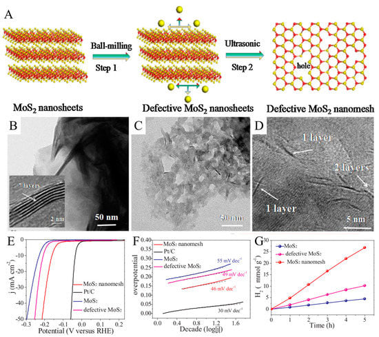
Figure 1.
(A) Schematic illustration of the fabrication of monolayer MoS2 nanomesh with defective atomic-sized pores in the basal plane for amplifying HER catalysis. TEM images of (B) pristine MoS2 nanosheets and (C) MoS2 nanomesh. (D) HRTEM image of the MoS2 nanomesh. Polarization curves (E) and Tafel slope (F) of Pt, MoS2 nanosheets, defective MoS2 nanosheets, and MoS2 nanomesh in 0.5 M H2SO4 at a scan rate of 5 mV. (G) H2 evolution rates on the EY-sensitized photocatalysts in 80 mL of 15% (v/v) TEOA aqueous solution under visible light irradiation (≥420 nm). Catalysts: 20 mg and EY: 20 mg. Reproduced with permission from [56] © 2018 Elsevier B.V.
By adjusting and improving the nanostructure of the material, the performance of the material in catalysis can be significantly optimized [52,53,54]. Through theoretical and experimental calculations, it was found that the preparation of an unsaturated and coordinated 1D metal Mo chain on the structure of MoS2 leads to a significant improvement of HER activity [57,58,59]. Figure 2A shows the formation of 1D Mo chains by removing S atoms from the MoS2 atomic layer. Such 1D Mo chains act as HER catalytic active sites on the surface. In the wake of the first formed S-vacancy, the adjacent S atoms present an unstable state, and thus tend to fall out of the lattice to form more S-vacancies. As a result, a line defect can be induced with the accumulation of the S-vacancies. Also, the longer the line defect, the higher the stability. S atoms are disengaged from MoS2 to form a quasi-one-dimensional Mo chain by inserting electrochemical sodium. The Mo chain can be observed in Figure 2B after phase correction and monochromatic processing of the Mo channel in the HRTEM image of MoS2. It can be observed that a single Mo chain, two parallel Mo chains, and three parallel Mo chains emerged after S-vacancies formed.
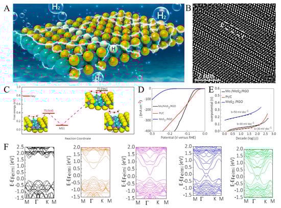
Figure 2.
(A) A schematic depicting 1D Mo chains created by successive removal of S atoms along a row. The Mo is shown in cyan, and S atoms are shown in yellow, respectively. (B) HRTEM images of 1D Mo channels in a MoS2 monolayer. (C) Free energy diagram of 1D Mo atomic chains for the HER following the Volmer–Heyrovsky pathway. (D) Comparison of the polarization curves obtained after 100 cycles for Mo/MoS2 and MoS2 catalysts on reduced graphene oxide (RGO) relative to that of Pt nanoparticles on a glassy carbon electrode. (E) Tafel plots obtained from the polarization curves. (F) The effect of increasing number of rows of 1D Mo atomic chain on the band structure. Reproduced with permission from [60], © 2019 Elsevier Ltd.
The HER free energy diagram through Volmer–Heyrovsky pathways was constructed to unravel its reaction mechanism. To gain a deeper understanding of the Tafel mechanism and kinetics of H atom recombination and release of H2, the quasi-1D Mo atomic chains were used as a representative to locate the minimum energy paths and the transition states via the nudged elastic band (NEB) method. The corresponding initial, intermediate or transition, and final states are displayed in Figure 2C. As the NEB method predicted, in Figure 2D, the quasi-one-dimensional Mo chain shows a low overpotential of 45 mV to achieve a current density of 10 mA cm−2, outperforming commercial Pt/C near the practically meaningful high-current region. The corresponding Tafel plots in Figure 2E showed that 1D unsaturated Mo chains in Mo/MoS2 reduce the Tafel slope from 90 mV dec−1 to 40 mV dec−1. The influence of Mo chains on HER can be inferred from the band structure of 2H-MoS2 with an increasing number of quasi-1D Mo atomic chains in Figure 2F. In the presence of Mo chains, new bands appear in the gap near the Fermi level, responsible for hydrogen adsorption on unsaturated Mo atomic chains. The corresponding Kohn–Sham orbitals for the band directly below the Fermi level indicate that these states are localized around the Mo chains.
The structure of MoS2 with the quasi-one-dimensional Mo chain is more conducive to the Tafel reaction’s rapid progression, making the H adsorption and release process more accessible. As a result, the hydrogen production rate has been dramatically improved.
A method is introduced to improve the catalytic hydrogen evolution performance of MoS2 nanosheets by using dislocation as a line defect [61]. The synthesis diagram of a high-density misaligned flexible MoS2 nanosheet is shown in Figure 3A; with ammonium molybdate tetrahydrate and high-concentration thiourea as precursors, MoS2 nanowire with high dislocation density can be prepared by hydrothermal reaction at low temperature for ten days. The formation mechanism of D-S-MoS2 is shown in Figure 3B, where [Mo7O24]2− decomposed by (NH4)6Mo7O24·4H2O produces two different sulfides under the action of a high concentration source of sulfur. After ten days of hydrothermal reaction without splicing, the two kinds of sulfide clusters gradually form MoS2 nanosheets with a weak crystalline structure, which show short-range order and relatively low crystallinity. It has a porous structure and abundant dislocations (in-plane and out-of-plane). The (100) crystal phase image with a large number of dislocations obtained by FFT processing is shown in Figure 3C due to the presence of plentiful dislocations (these dislocations are represented by “T”); in-plane strain appears at the corresponding position. In addition, dislocations in one crystal phase may lead to strain effects in another crystal phase, and dislocations are not included in the same region and are marked with white squares. The synthesized D-S-MoS2 not only has an in-plane dislocation structure but also shows an out-of-plane dislocation structure. The formation mechanism of out-of-plane dislocations is shown in Figure 3D. The strain induced by the dislocations can cause the surface of MoS2 nanosheets to be raised or sunken, resulting in interlayer lattice distortion and a more significant Burger vector. The sharp edge dislocations indicate that they are caused by atomic slippage.
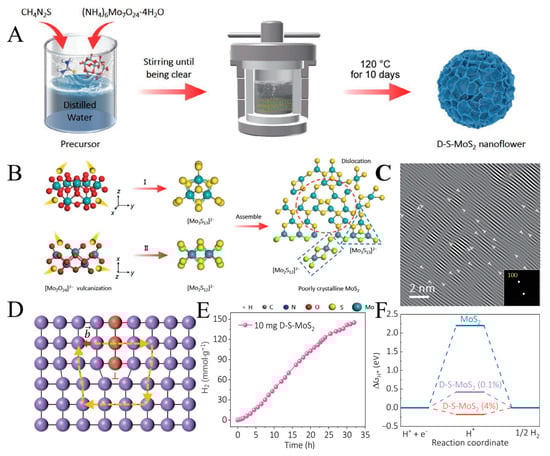
Figure 3.
(A) Schematic diagram of synthetic high-density dislocation intrinsic flexible MoS2 nanosheets. (B) Schematic diagram of low temperature hydrothermal processing. (C) The (100) crystal phase images containing numerous dislocations obtained by IFFT processing, in which the dislocations are represented by “T”. (D) Schematic illustration of edge dislocations. (E) Time courses of photocatalytic H2 evolution over D-S-MoS2. (F) Gibbs free energies of D-S-MoS2 at different lattice compressibility. Reproduced with permission from [62], © Tsinghua University Press 2022.
The time course of photocatalytic hydrogen evolution on D-S-MoS2 is shown in Figure 3E, and hydrogen production linearly increases with irradiation time. The results show that it has not only good hydrogen evolution performance but also has specific stability. The Gibbs free energy of D-S-MoS2 at different lattice compressibility is shown in Figure 3F. Dislocations usually consist of different structural motifs, of which 5/7 nuclei are more accessible to obtain due to their lower formation energy. This article uses a 5/7 dislocation core as a model. From a thermodynamic point of view, the ideal Gibbs free energy value for hydrogen adsorption is 0 eV [63]. The strain effect caused by dislocations causes the lattice to stretch or contract. In contrast, the presence of high-density dislocations causes the lattice to compress by 0.1~4%, as can be seen from the diagram when the lattice compression ratio is 0.1%, the ΔGH of D-S-MoS2 is about 0.42 eV and can be optimized to −0.18 eV when the lattice compression ratio is 4%. The results show that the dislocation–strain interaction is a crucial factor in improving the activity of the catalyst.
The discovery of moiré superlattices (MSLs), caused by the twisting of van der Waals force-stacked two-dimensional layered materials, [64,65]. Research on the relationship between this unique structure and electrical properties has become a hot topic in electrocatalysis [66,67,68]. Zhao et al. proposed a new method to synthesize two-dimensional MSLs [69]. A one-step solvothermal method was used to prepare helical WS2 nanobelts with local torsion deformation, and moiré stripes were formed due to the torsion angle between the layers. A single conical tube curled from one end of the WS2 nanobelt can be observed through a scanning transmission electron microscope, as shown in Figure 4A. WS2 nanobelts are easily twisted by force imbalances during synthesis [55,70], forming a nano-cone at one end. The relative stress distribution can be known through finite element analysis, as shown in Figure 4B. Strain generation may activate the substrate of the nanobelts [62,71], primarily by altering the electronic structure of the active catalytic site and facilitating mass transfer. The strain generated by the distortion weakens the van der Waals forces between the corresponding multilayer WS2 nanobelts, causing a high probability of layer slip formation. As shown in Figure 4C, honeycomb moiré patterns due to layer slip are observed through HRTEM. Further analysis of the production of moiré patterns in Figure 4D shows a simulation diagram of the atomic structure of WS2 MSLs. Twisting can be observed between nanofilm layers at an angle of 14°. Twisting and folding can easily cause S atoms to slide in the WS2 MSLs to produce 1T′-WS2, for which the ΔGH of 14° twisted bilayer 1T′-WS2 NSs is calculated using density functional theory (DFT). The experimental data showed that the ΔGH of 1T′-WS2 MSLs’ basal plane site (−0.24 eV) was close to zero, indicating high activity of the HER. As an HER catalyst, WS2 MSLs have a unique structure due to strain and phase engineering, which promotes the generation of active sites on the basal plane and dramatically reduces the ΔGH of sites. At the same time, it also allows other TMDs to be used for MSL engineering. This research on MSLs dramatically expands the research direction of topophysical engineering based on mechanical flexibility. It provides a broad idea for designing catalysts for more diversified structures in the future.
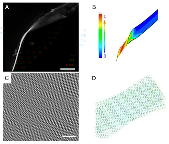
Figure 4.
(A) STEM image of single screwed WS2 nanobelt. Scale bar, 300 nm. (B) Finite-element calculations of strain in a nano-cone. The color bar shows the relative scale of the strain distribution. (C) High-resolution transmission electron microscopy (HRTEM) characterization of as-prepared WS2 nano-cone. Scale bar, 2 nm. (D) Schematic diagram of the WS2 MSLs. A twist angle of 14° is set in the bilayer regions and distinctive moiré patterns are clearly shown. Yellow and cyan balls represent S and W atoms. Reproduced with permission from [69], © The Author(s), 2021.
2.2. Doping Engineering
Heteroatom doping is considered to be an effective method to enhance catalytic activity. Ni atoms are doped to replace Mo, and the induced SV formation and phase transition will transform into a stable distorted 1T′ phase [72,73]. 1T′-MoS2 SV is a catalyst with a high electrical conductivity that integrates all multifunctional active sites, which is expected to enhance HER activity. Ni atomic doping can introduce SV and trigger phase transition to control the electronic structure of MoS2 [74,75,76], as shown in Figure 5A, including three aspects of defect engineering, phase transition, and electronic features. This method of doping low-valent metal atoms ensures more exposure to active sites at the edge of MoS2 nanosheets. It is another important way to improve the catalytic performance of HERs.
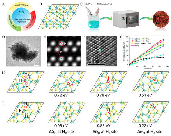
Figure 5.
(A) Electronic structure regulation to improve MoS2 catalytic performance, including defect engineering, phase transition, and electronic features. (B) Structural modules of Ni-doped 1T′-MoS2. (C) Process schematic of the composite of synthesis of Ni-doped 1T′-MoS2. (D) TEM image of the synthesis of Ni-doped 1T′-MoS2, scale bar: 200 nm. (E) Simulated image of 1T′ phase for MoS2. (F) HAADF-STEM characterization of Ni-1T′-MoS2. (G) Corresponding cumulative hydrogen yield. (H,I) Structural models for the DFT calculations of 1T′-MoS2 SV and Ni-1T′-MoS2 SV. Reproduced with permission from [77], © Tsinghua University Press 2022.
The atomic structure of Ni-doped 1T′-MoS2 is shown in Figure 5B. In general, a regular octahedron with Ni doping as the center and S as vertices is formed, in which S0–S5 represents the S atoms connected to the doping atoms. Compared with the undoped 1T′-MoS2 structure, DFT can calculate the respective SV formation energies. The analysis shows that the SV formation energies around Ni atoms in Ni-doped 1T′-MoS2 are much lower, indicating a high concentration of SVs is generated in the structure after doping with Ni atoms and that the conversion of semiconducting MoS2 to metallic MoS2 can be accelerated due to the existence of SVs. The primary process for the preparation of Ni-doped 1T′-MoS2 is illustrated in Figure 5C. The preparation mainly used three crystalline substances, (NH4)6Mo7O24·4H2O, NiSO4·6H2O, and CH4N2S. Firstly, a certain amount of (NH4)6Mo7O24·4H2O as a reducing agent and an excess amount of CH4N2S as a source of S are completely dissolved in a solution of NiSO4·6H2O as a source of Ni. Moreover, the two crystals are evenly distributed in the solution, and the desired solution can be obtained when thoroughly combined. Then the solution was dried in a vacuum oven at 200 °C for 24h, and the final drying was completed to obtain Ni-doped 1T′-MoS2.
Transmission electron microscopy (TEM) scanning was carried out in the experiment. The Ni-doped 1T′-MoS2 has a sheet-like structure in the nanoscale, as illustrated in Figure 5D. In order to further understand the electronic structure of Ni-doped 1T′-MoS2, a high-precision observation instrument is used in Figure 5E. Two parallel rows of bright spots (Mo atoms) were close to each other to form a one-dimensional zigzag Mo atom chain, which also illustrates the asymmetric feature of the distorted 1T′ structure. The two red dashed lines b and c in the figure can also show in further experiments that there is a sizeable Mo-Mo gap in the structure of 1T′-MoS2. As shown in Figure 5F, the experimental characterization of Ni-1T′-MoS2 by high-angle annular dark-field scanning transmission electron microscopy (HAADF-STEM) shows that the structural phase matches well with 1T′-MoS2. The effect of Ni-doped 1T′-MoS2 catalysts on the hydrogen production index under different catalyst dosages is shown in Figure 5G. The black curve in the figure represents the cumulative hydrogen yield under the influence of only solution eosin Y (EY) (without Ni-doped 1T′-MoS2). It can be seen that the cumulative hydrogen yield is almost unchanged after 90 min, which indicates that water splitting has stopped after this. Furthermore, compared with other samples with linear function curves of Ni-doped 1T′-MoS2 catalysts, this also means that their hydrogen production almost maintains the original growth rate throughout the experimental time. It can also be seen from the figure that the optimal sample value is 10 mg, and the hydrogen evolution value is 91.625 μmol·h−1.
DFT calculations are further performed to explore the effect of Ni-1T′-MoS2 SV on the catalytic activity. The Gibbs free energy (ΔGH) of hydrogen adsorption for 1T′-MoS2 SV and Ni-doped 1T′-MoS2 SV at three different active sites H0-H2 is shown in Figure 5H and Figure 5I, respectively. By comparing the two figures, it can be seen that the ΔGH of the corresponding active sites decreases sharply after Ni doping. This clearly shows that Ni-doped 1T′-MoS2 has an optimized ΔGH and confirms that Ni-doping enhances the H adsorption capacity and thus activates the SV. This synthetic method of doping low-valent metal atoms opens a new route to synthesize diverse active sites and enables the study of doping-dependent properties and applications.
The catalytic activity of MoS2-based catalysts would be affected by the existing oxygen in the photocatalytic hydrogen evolution reaction [78,79,80,81]. The mechanism of the atomic oxygen doped in intrinsic flexible MoS2 is further explored through theoretical analysis and experiments [82,83,84,85]. A Bader analysis based on the experimental data is performed at the start, as shown in Figure 6A. The oxygen substitution site has excellent electron affinity, which is beneficial for proton attraction and thus improves HER efficiency. In addition, strain engineering basis on O-doping is implemented. The synergistic effect of oxygen doping and strain engineering adjusts the catalytic activity of MoS2-based catalysts. Figure 6B shows the influence of O-doping and strain engineering on the band gap of MoS2. Single-layer MoS2 is a direct band gap semiconductor, and after oxygen doping, it becomes an indirect band gap semiconductor. It can be found that oxygen doping and strain can reduce the band gap of MoS2, and the strain could evidently change the band gap.
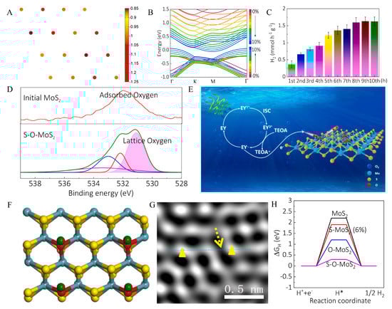
Figure 6.
(A) Bader charge analysis of the Mo16S31O surface reveals the electron acceptor ability of O-doping site characterized by −1.22 eV negative charge compared to −0.85 eV on the S atoms. (B) Marked band structure changes for MoS2 with O-doping as a function of strain. As the strain increases (0~10%), the bands move downward and upward close to the Fermi level, causing bandwidth to be reduced. (C) Photo-catalytic properties of MoS2 with 1.2 mL O2 amount treatment at each hour in the PHER process. The gas content was monitored every 15 min via an online gas chromatograph. (D) High-resolution XPS spectrums of O1s for original MoS2 and S-O-MoS2. (E) The formation mechanism of MoS2-xOx in actual photo-catalytic reactions. (F) Schematic of the top (upper panel) views of strained MoS2 with O-doping on the basal plane, where O atom sites serve as the active sites for hydrogen evolution. (G) HAADF-STEM images of strained MoS2 with O-doping. (H) ΔGH diagram of hydrogen evolution in the pristine MoS2, strained MoS2 (S-MoS2, 6% strain), MoS2 with O-doping (O-MoS2, 25 atoms% O), and strained MoS2 with O-doping (S-O-MoS2, 6% strain, 25 atoms% O). Reproduced with permission from [82], © 2020 Elsevier B.V.
In order to explore the effect of oxygen doping on the catalytic hydrogen evolution activity of MoS2 in the actual process, the change of hydrogen production rate per hour in the hydrogen evolution process is elaborately recorded through experiments, as shown in Figure 6C. The maximum hydrogen production rate of oxygen-doped MoS2 can reach 1.6 mmol h−1 g−1. The catalytic activity of the catalyst tends to be stable with the increase in catalytic time, which confirms that oxygen doping improves the actual catalytic effect of MoS2.
The internal structure and properties of MoS2 doped with oxygen were analyzed by XPS, as shown in Figure 6D. It can be found that the formation of Mo-O bonds and O with more electron contribution ability to reduce the electron density around the substitution site, resulting in the decrease in binding energy.
Figure 6E is the formation mechanism of MoS2−xOx in actual photo-catalytic reactions. The sensitizer EY is irradiated by sunlight to produce excited state EY1*, which can easily become triplet EY3* under the action of ISC. Through the reduction quenching of TEOA, electrons and free radicals EY− are produced, and electrons are easily transferred from EY− to O2 to produce highly active O2−, which reacts with MoS2 to produce MoS2−xOx. The top schematic of MoS2 doped with O on the base surface is shown in Figure 6F. It is easy to observe the oxygen substitution site as the active site of the hydrogen evolution reaction. Figure 6G shows HAADF-STEM images of the lattice distortion of MoS2 with O-doping. The formation of O-Mo bonds may be the reason for the strain in the internal structure [86,87,88]. ΔGH is an important indicator for the hydrogen evolution reaction activity of the catalyst. In order to study the synergistic effect of oxygen doping and strain on HER performance, the DFT calculation method was used. The calculation results clearly show in Figure 6H that the ΔGH of oxygen-doped strain MoS2 is the lowest, only 0.3 eV. Overall, the synergistic effect of oxygen doping and strain on MoS2 could greatly improve its catalytic hydrogen evolution rate, which provides new insights and new ideas for preparing efficient photocatalysts in the future.
2.3. Phase Engineering
As shown in Figure 7A, vertical 1T-WS2 nanosheets were prepared on a flat Ti substrate to improve HER catalytic efficiency. The nanosheets are cross-linked, facilitating the exposure of WS2 edge sites and the rapid transport of protons throughout the catalyst, thus enhancing H2 evolution. Figure 7B shows that the 1T-WS2 nanosheets are very transparent, implying that the nanosheets are ultrathin [89]. One of the white luminescent lines represents its good conductivity, which is crucial for H2 evolution. X-ray photoelectron spectroscopy (XPS) can confirm the chemical state and composition of 1T-WS2 and distinguish the different metallic phases of WS2. Figure 7C indicates that the WS2 nanosheets are a mixture of 1T and 2H phases [90,91]. The Tafel plots in Figure 7D were measured in a 0.5 M H2SO4 solution using a typical three-electrode cell setup. The Tafel slope is an important parameter to describe the HER activity of the catalyst. The black linear part of the figure is the Tafel plot of a vertical 1T-WS2 nanosheet at a small overpotential, which has a Tafel slope of 43 mV dec−1. The Tafel slopes of Pt/C and WS2 nanosheets are 52 mV dec−1 and 30 mV dec−1, respectively. As shown in Figure 7E, the polarization curves of the 1T-WS2 nanosheets after 5000 cycles almost overlapped with those of the initial cycles. This demonstrates that the vertical 1T-WS2 nanosheets are very stable in the acidic environment and remain intact during repeated cycles. Figure 7F examines the ability associated with the continuous catalytic generation of H2 from vertical 1T-WS2 nanosheets using time measurements (j–t). This quasi-electrolytic process was carried out in 0.5 M H2SO4 at a constant voltage of 160 mV. Apparently, the current density curve presents almost a horizontal line in the 30 h test at a continuous current density, which indicates the ultra-high stability of the vertical 1T-WS2 nanosheets.
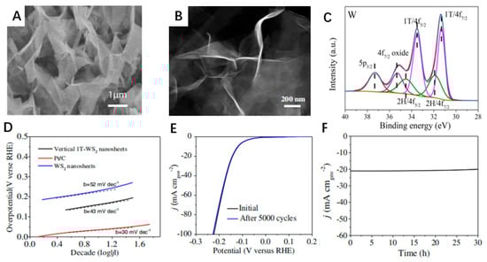
Figure 7.
(A) Top-view SEM image of a vertical 1T-WS2 nanosheet prepared on a Ti substrate. (B) HAADF-STEM images of 1T-WS2 nanosheets. (C) XPS spectra of W 4f binding energy of vertical 1T-WS2 nanosheets. (D) Tafel plots of Pt/C, WS2 nanosheets, and vertical 1T-WS2 nanosheets in 0.5 M H2SO4 at a scan rate of 5 mV/s. (E) Durability test showing negligible current loss even after 5000 CV cycles. (F) time dependence of the current density curve at an overpotential of 160 mV versus RHE for vertical 1T-WS2 nanosheets. Reproduced with permission from [46], © The Author(s). 2018.
2.4. Strain Engineering
Strain is one of the most common means of changing the structure of a catalyst to improve its HER performance. The electronic, magnetic, and catalytic properties of materials can be enhanced by topology [92]. The aqueous solution electrochemical activation method can promote the topological transformation of WS2 from the 2H phase to the 1T phase [93]. The phase transition caused by this strain greatly improves the catalytic performance of the spiral-shaped 1T phase of WS2 [94]. Figure 8A shows the relationship between the number of potential cycles and the cathode current density. It can be seen that the early current density increases significantly with the increase in the number of cycles and the current density stabilizes after 10,000 cycles. The high stability of WS2 is maintained even after 20,000 cycles. It can be seen that WS2 nanosheets are the ideal catalysts for long-term electrochemical processes. To explore the main reason for the above outstanding performance of WS2, in situ Raman spectroscopy of WS2 nanosheets was implemented, as shown in Figure 8B. It can be seen that the peaks of the Raman activity pattern corresponding to the 1T phase become sharper and more prominent. By calculating the area under the peak, it is found that the proportion of 1T is 70% and the proportion of 2H is 30% due to the strain that causes the WS2 nanosheets to transition from the 2H phase to the 1T phase. The electrochemical activity of the WS2 nanosheets is improved because the transition phase reduces the charge transfer resistance. As shown in Figure 8C, the morphology of the WS2 nanosheets also evolves during the cycle. As the number of cycles increases, the WS2 nanosheets gradually twist and rotate from the original straight to helical.
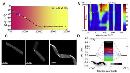
Figure 8.
(A) Change in the HER cathodic current density (at –0.20 V vs. RHE) with the number of potential cycles. (B) In situ Raman spectroscopy as a function of CV cycles (phase transformation process). (C) Morphological evolution of WS2 nanobelts with an increasing number of cycles. (D) Comparison of the influence of different sites and strains for the 1T- and 2H-WS2 phases on the HER performance. ΔGH diagram of the different H adsorption sites. The inset is a TEM image (with false color) of WS2 nanohelices. Reproduced with permission from [83], © 2019 Elsevier B.V.
The driving force of the process from straight to helical is the strain in the WS2 nanohelices caused by the H2 bubbles. In Figure 8D, we introduced Gibbs free energy for comparison to understand further the effect of different strains and phases on the catalytic performance of WS2 nanohelices. The closer the value of Gibbs free energy is to 0, the better the balance between the absorption and removal of hydrogen atoms at the active site is. The 1T phase WS2 nanohelices at 3% strain have the best catalytic performance because the Gibbs free energy is closest to 0. For comparison, the Gibbs free energy of strain on WS2 nanobelts in the 2H phase was also calculated, and it was found that the strain had no effect on its catalytic performance. From these data, we can draw a conclusion that the strain has caused the transformation of WS2 nanosheets from the 2H phase to the 1T phase. The synergy of strain and phase transition leads to decreasing charge transfer resistance, increases in activity at each active site, and increases in the number of spiral-shaped active sites of WS2 nanosheets. All these changes have a positive effect on the HER of WS2 nanosheets.
Structural engineering offers a promising strategy to artificially regulate and control catalysts’ inherent activity in electrocatalysis and photocatalysis, thus achieving catalytic targets for specific scenarios. Table 1 summarizes the performance of different catalyst modified by structural engineering in recent advances.

Table 1.
Comparison of HER performance on different catalysts modified by structural engineering.
3. As Co-Catalyst to Compound with Various Semiconductors
The number of exposed active edges of MoS2 nanosheets is the key to the catalytic activity of MoS2 for HER [104,105,106]. Making single- or few-layer MoS2 nanosheets vertically stand on a substrate with maximally exposed edge sites is a reasonable way to enhance HER catalytic activity [107]. Porous TiO2 nanofibers with abundant defects are appropriate for MoS2 nanosheets to grow as nucleation centers. Single- or few-layer MoS2 nanosheets standing vertically on porous TiO2 nanofibers (TiO2@MoS2) were successfully prepared by a simple hydrothermal method, as illustrated in Figure 9A. Firstly, the Na2MoO4 and C2H5NS were dissolved in deionized water to form a transparent solution. Then TiO2 nanofibers were immersed into the above solution and stirred to obtain a suspension. The extremely tough and porous TiO2 nanofibers with vast numbers of defects can easily interact with metallic precursors and then act as nucleation for the growth of MoS2 nanosheets. MoS2 embryos grew from inside to outside of the pores of TiO2 nanofibers. The dark field FESEM-STEM images of the TiO2@MoS2 heterostructures are shown in Figure 9B. It can be seen that the transparent, flexible, and curly MoS2 sheets with a lateral size of about 100 nm vertically stand on the surface of TiO2 nanofibers. The shapes of MoS2 nanosheets that grow vertically in the dioxide pores of TiO2 nanofibers are similar to tender shoots growing on the surface of bamboo. The photocatalytic HER mechanism of the TiO2@MoS2 heterostructure in Figure 9C indicated that the growing method ensures the 2D MoS2 nanosheets are firmly attached to the TiO2 nanofibers. The mechanism of TiO2@MoS2 heterostructure can not only strengthen the contacts between TiO2 and MoS2 but also accelerate electron transfer in the TiO2@MoS2 heterostructures. To further improve the HER catalytic activity of the TiO2@MoS2 heterostructure, the MoS2 nanosheets in the TiO2@MoS2 heterostructure were exfoliated by Li intercalation. Then, the 1T phase of MoS2 could be obtained, as shown in Figure 9D. Figure 9E indicated that the excited S vacancies and strain were the main reason for the stability of the 1T phase by reducing the surface energy.
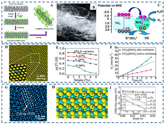
Figure 9.
(A) Schematic illustration for the nucleation and growth of MoS2 nanosheets. (B) Dark field FESEM-STEM image of TiO2@MoS2 heterostructures. (C) Schematic illustration of the energy band structure of the TiO2@MoS2 heterostructure and the proposed charge transfer mechanism. (D) HRTEM images of the MoS2 in TiO2@MoS2 exfoliation by Li-ion intercalation. (E) Difference between the surface energies of the 1T and 1H phase MoS2 phases as a function of strain with various concentrations of S vacancies. (F) H2 accumulation over exfoliated TiO2@MoS2 (G) HRTEM image of the MoS2 in the exfoliated TiO2@MoS2 after seven hours HER. (H) Supercells for H adsorption on the surface of single-layered 1T′-MoS2 (I) Calculated Gibbs free energies for H adsorption under strain from 0% to 3.0% for 1T′-MoS2. Reproduced with permission from [84], © 2017 Wiley-VCH Verlag GmbH & Co. KGaA, Weinheim.
As shown in Figure 9F, the amount of H2 evolution of TiO2@MoS2 heterostructure after exfoliation showed a nonlinear increase compared with the TiO2@MoS2 before exfoliation. The phenomena indicate that the active sites of the TiO2@MoS2 after exfoliation had been optimized during the process of PHER. To uncover the self-optimization mechanism, an enlarged HRTEM image of MoS2 in exfoliated TiO2@MoS2 after seven hours of HER was obtained as shown in Figure 9G. The distorted 1T′ phase with the super-lattice structure from Mo atom clustering into zigzag chains can be clearly observed. Figure 9H shows eight S sites with different H adsorption coverages. The relationship between Gibbs free energy and strain of 1T′ phase was conducted in Figure 9I. It is easy to find that 1T′ phase is highly active for the HER and the strain has huge influences on the catalytic activity of the MoS2 basal plane.
To achieve idealized photocatalytic H2 evolution performance under visible light irradiation, the TiO2 nanofibers of TiO2@MoS2 could be replaced by narrow bandgap semiconductor CdS nanowires to design a CdS/MoS2 heterojunction. The CdS/MoS2 heterojunction was produced by a simple hydrothermal reaction with or without adding glucose. With the help of glucose, the MoS2 nanosheets grow nearly vertically on the CdS nanowires, which allows a high exposure of the active edge sites and improves the charge separation and transfer rates. In addition, glucose can make MoS2 thinner and can act as a binder to help MoS2 nanosheets grow along the longitudinal axis, simultaneously forming 1D/2D nearly vertical CdS/MoS2 heterojunctions for efficient photocatalytic hydrogen evolution. Figure 10A shows the synthesis process of CdS/MoS2(G) and CdS/MoS2(W) heterojunctions by a two-step solvothermal approach. As shown in Figure 10B,C, the MoS2 nanosheets are grown nearly perpendicularly to the CdS nanowires with an acid of glucose, while MoS2 nanosheets are discrete connected to the CdS nanowires without glucose. The TEM image of CdS/MoS2 heterojunctions in Figure 10D further indicates that MoS2 nanosheets grow almost vertically on the outer surface of CdS nanowires. Figure 10E shows that the layer number of MoS2 nanosheets is almost 1–2 layers, indicating a reduced tendency of MoS2 nanosheet agglomeration.
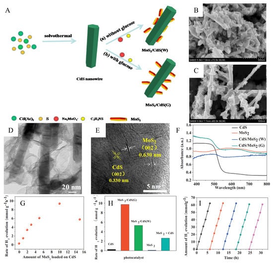
Figure 10.
(A) Schematic illustration of the growth processes of CdS/MoS2 heterostructures under different conditions (a) without glucose and (b) with glucose. (B) CdS/MoS2(W) composites prepared without adding glucose. (C) CdS/MoS2(G) composites prepared with the addition of glucose. (D) TEM images show the nearly vertical structure of CdS/MoS2(G) composites. (E) HRTEM images of CdS/MoS2(G) composites. (F) UV–vis spectra of MoS2, CdS, CdS/MoS2(W) and CdS/MoS2(G) samples. (G) Average photocatalytic H2 evolution rate over CdS/MoS2(G) loaded with different amounts of MoS2. (H) comparison of H2 evolution rate on CdS, CdS/MoS2(G) 10 wt%, and CdS/MoS2(W) 10 wt%, MoS2 nanosheets, and the physical mixture of 10 wt% MoS2 and 90 wt% CdS. (I) Cycling test of photocatalytic H2 evolution for CdS/MoS2(G) samples. Reproduced with permission from [43], © 2017 Elsevier B.V.
Figure 10F shows the UV diffuse reflectance spectra (DRS) of CdS, MoS2, CdS/MoS2(W) and CdS/MoS2(G) samples. The light-harvesting ability of the CdS/MoS2(G) sample is higher than that of the CdS/MoS2(W) sample in both the UV and visible regions, which indicates that the MoS2 nanosheets have better adhesion on the CdS nanowires and the open near-vertical structure of the CdS/MoS2(G) sample has almost no effect on the light absorption of the CdS core. Figure 10G shows the photocatalytic hydrogen production activity of CdS/MoS2(G) catalysts with different MoS2 loadings under visible light irradiation. With the increasing MoS2 content in the heterojunction, the H2 evolution rate of CdS/MoS2(G) increases. Even if the loading of MoS2 on the CdS/MoS2(G) heterojunction is 1 wt%, the hydrogen production rate is higher than that of pure CdS. The hydrogen production performance achieves the best maximum value of 9.73 mmol h−1 g−1 when the MoS2 loading contents reaches 10 wt%., It is 36.04 times higher than that of pure CdS nanowires. However, the degradation of photocatalytic performance appeared when the MoS2 content exceeded 10 wt%, the decline being due to the excessive MoS2 hindering the absorption of visible light by CdS. In addition, the high overlap of MoS2 also reduces the exposure of active sites, thus weakening photocatalytic H2 evolution. Figure 10H shows that the H2 evolution rate of CdS/MoS2(G) is the highest and much higher than that of CdS/MoS2(W). This indicates that the almost vertical MoS2 nanosheets on CdS/MoS2(G) maximally expose the HER active edge, thus enhancing H2 evolution. In contrast, the MoS2 nanosheets on CdS/MoS2(W) with random orientation and severe aggregation inhibit H2 evolution. In addition, the physical mixture of CdS nanowires and MoS2 nanosheets showed poor HER activity, indicating that the close contact between MoS2 and CdS is an important factor for H2 evolution. The CdS/MoS2(G) catalyst exhibits the best hydrogen production rate due to the near-vertical nanostructure and the tight heterogeneous interface. Figure 10I show that the CdS/MoS2(G) heterojunction was tested for five reaction cycles under visible light irradiation. The test data indicate that the introduction of MoS2 has the function of inhibiting the photocorrosion of CdS, which leads to the good stability of CdS/MoS2(G). The nearly vertical and open structure can provide an optimal electron transport pathway and a high density of active sites; thus, the electron-hole pair separation and photocatalytic performance are improved.
To further enhance the photocatalytic hydrogen production activity of TiO2@MoS2 heterostructure, zero-dimensional CdS nanocrystals acting as the light-harvesting centers could be loaded onto the MoS2 nanosheets in TiO2@MoS2 heterostructure to broaden the light absorption range of the catalyst. The fabrication process of the TiO2@MoS2@CdS heterostructure with a “cauline-leaf” structure is shown in Figure 11A. This delicate structural design helps to increase the specific surface area and enhance light capture. The TEM image of TiO2@MoS2@CdS is shown in Figure 11B. The MoS2 nanosheets grow vertically on TiO2 nanofibers, and the CdS nanoparticles are uniformly distributed on the surface of the MoS2 nanosheets. The presence of a single or few layers of MoS2 nanosheets in Figure 11C indicates that the MoS2 nanosheet is ultrathin. The good crystallinity of MoS2 and CdS could be confirmed by clear lattice stripes in Figure 11D. The apparent lattice distortion at the interface can indicate that the perfect heterostructure is formed between MoS2 and CdS.
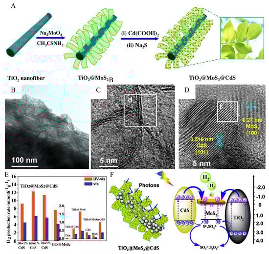
Figure 11.
(A) Schematic illustration of the processing steps to prepare TiO2@MoS2@CdS “cauline-leaf”-like structure. (B) TEM image, (C) HRTEM image with (d) 0.61 nm lattice spacing, and (D) HRTEM image of TiO2@MoS2@CdS with (f) lattice distortion. (E) The photocatalytic hydrogen production activities of TiO2@MoS2@CdS (50, 60, and 70 wt%) CdS and CdS@MoS2 with the optimum amount of 95 wt% CdS under simulated solar light (320–780) nm or visible light (>420 nm) irradiation at zero potential. The reaction was conducted with 20 mg of photocatalysts in an 80 mL mixed aqueous solution (pH 13.2, 0.35 M Na2S, 0.25 M Na2SO3). TiO2@CdS, TiO2@MoS2, CdS, MoS2 nanosheets and the physical mixture of 40 wt% TiO2@MoS2 and 60 wt% CdS. (F) Illustration of the HER mechanism over TiO2@MoS2@CdS under simulated solar light irradiation. Reproduced with permission from [85], © 2016 Elsevier B.V.
The photocatalytic hydrogen production activity of TiO2@MoS2@CdS with different CdS content under simulated sunlight (320–780 nm) or visible light (>420 nm) irradiation is shown in Figure 11E. When the content of CdS reached 60 wt%, the highest H2 yield was 12.3 or 6.2 mmol h−1 g−1. In the simulated sunlight irradiation, the photocatalytic HER mechanism of TiO2@MoS2@CdS is shown in Figure 11F. The multistage biomimetic cauline-leaf structure facilitates light capture and absorption by photon scattering and multiple absorption effects. The gradient of energy levels between different semiconductors promotes the transfer of photogenerated carriers. The photogenerated electrons are eventually transferred to the enriched edge-exposed MoS2 to produce hydrogen. This delicate structure design is crucial for the development of photocatalysis. This perfect “cauline-leaf” design is essential for developing photocatalytic materials.
The key to photocatalytic efficiency for hydrogen evolution reactions lies in the development and utilization of catalytic materials [108,109,110,111]. Among many semiconductor photocatalysts, ZnIn2S4 has attracted the attention of researchers due to its stable chemical properties, narrowband gap, and excellent photoelectric properties [112,113,114]. However, ZnIn2S4 has a high recombination rate of photogenerated carriers in the hydrogen evolution reaction, which could be solved by loading MoS2 as cocatalysts [115,116]. The main active sites of MoS2 are located at the edge, while this sandwich-layered structure formed by van der Waals force leads to its very inert basal plane. Ni atoms doped in MoS2 would activate its inert basal plane. Firstly, ZnIn2S4 and Ni-Mo-S were synthesized by a simple solvothermal and hydrothermal method, and the preparation process is shown in Figure 12A. The prepared ZnIn2S4 and Ni-Mo-S powders were uniformly mixed by grinding in a specific proportion in a mortar. Finally, ZnIn2S4/Ni-Mo-S composite materials were formed.
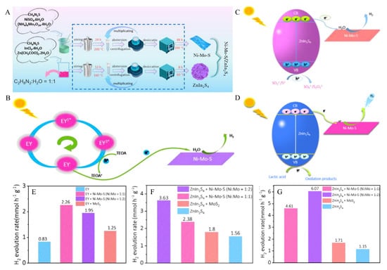
Figure 12.
(A) Schematic illustration of the synthesis of Ni-doped MoS2/ZnIn2S4 composite. (B) Diagram of the carrier migration process of Ni-Mo-S in EY/TEOA aqueous solution (pH 7) under visible light irradiation. (C) Schematic of the charge carrier migration process of ZnIn2S4/Ni-Mo-S composite materials in Na2S/Na2SO3 aqueous solution (pH 13.2) under visible light irradiation. (D) Schematic of the charge carrier migration process of ZnIn2S4/Ni-Mo-S composite materials in lactic acid aqueous solution (pH 2.5) under visible light irradiation. (E) Comparison of photocatalytic H2 evolution activities over EY, MoS2/EY, Ni-Mo-S/EY (Ni:Mo = 1:2), and Ni-Mo-S/EY (Ni:Mo = 1:1) in EY/TEOA aqueous solution (pH 7). (F) Comparison of photocatalytic H2 evolution activities over ZnIn2S4, MoS2/ZnIn2S4, ZnIn2S4/Ni-Mo-S (Ni:Mo = 1:2), and ZnIn2S4/Ni-Mo-S (Ni:Mo = 1:1) in Na2S/Na2SO3 aqueous solution (pH 13.2). (G) Comparison of photocatalytic H2 evolution activities over ZnIn2S4, MoS2/ZnIn2S4, ZnIn2S4/Ni-Mo-S (Ni:Mo = 1:2), and ZnIn2S4/Ni-Mo-S (Ni:Mo = 1:1) in lactic acid aqueous solution (pH 2.5). Reproduced with permission from [42], © 2021 Published by Elsevier B.V. on behalf of Chinese Chemical Society and Institute of Materia Medica, Chinese Academy of Medical Sciences.
In order to meet the needs of photocatalytic hydrogen production under different media environments, three hydrogen evolution experimental systems were designed under neutral, alkaline and acidic conditions. To evaluate the HER catalytic activity of Ni-Mo-S nanosheets in the neutral medium environment, the prepared Ni-Mo-S nanosheets were used as the photocatalyst, EY was used as the sensitizer, and TEOA was used as the hole scavenger. Figure 12B shows the photocatalytic hydrogen evolution process of EY/Ni-Mo-S in TEOA aqueous solution under visible light irradiation. As a sensitizer with excellent photocatalytic hydrogen production performance, EY can absorb visible light from the ground state to single-line excited state EY1* after being excited by light with energy greater than the band gap. The single-line excited state EY1* has a short lifetime, which is easy to compound and causes fluorescence quenching. However, the single-line excited state electrons are easy to transform into triple excited state EY3* with a long lifetime through inter-system crossing (ISC) through gap hopping. Subsequently, electrons were extracted from TEOA by reductive quenching, resulting in free radicals EY− and TEOA+. It is easy to transfer electrons from highly reducible EY− to the conduction band of Ni-Mo-S nanosheets, resulting in the spatial separation of photogenerated charges and inducing H+ reduction from H2O decomposition to generate excited state H*. Two excited states H* react with each other to produce H2. At the same time, the holes generated on the valence band of Ni−Mo−S nanosheets will be consumed by TEOA to generate the oxidation donor (TEOA+).
In terms of acidic and alkaline media environments, we studied the hydrogen evolution reaction mechanism under the conditions of Na2S/Na2SO3 and lactic acid as hole sacrificial agents by using visible light irradiation on ZnIn2S4/Ni-Mo-S composites. We can observe the carrier migration in different media environments in the photocatalytic process in Figure 12C,D, respectively. Under visible light irradiation, ZnIn2S4 generates photogenerated carriers from the valence band (VB) to the conduction band (CB). However, because the conduction band of Ni-Mo-S is higher than that of ZnIn2S4, the photogenerated electrons of ZnIn2S4 transfer easily to Ni-Mo-S. In ZnIn2S4/Ni-Mo-S composites, which are closely bound, the photogenerated carriers can be effectively separated, and the recombination and other consumption of photogenerated carriers can be avoided. The H+ decomposed by H2O is reduced to the excited state H* under the action of electrons, and then the H* of the two excited states are combined to produce H2.
For the photocatalytic properties of Ni-Mo-S/EY with different Ni doping amounts, the experimental results can be obtained from Figure 12E. Without any semiconductor as a catalyst, photogenerated carrier recombination rate is high, and pure EY dye shows low photocatalytic hydrogen evolution activity. When pure MoS2 (Ni:Mo = 0) was used as a catalyst, the hydrogen evolution rate of EY/MoS2 under visible light was 1.25 mmol h−1 g−1. When the ratio of Ni:Mo in Ni-Mo-S was increased, the amount of hydrogen evolution increased. Through experiments, it was found that the catalytic performance was better when the ratio of Ni:Mo in Ni-Mo-S was 1:1. The maximum production rate of H2 reached 2.26 mmol h−1 g−1, 2.72 times that of pure EY dye photocatalytic hydrogen evolution, indicating the superiority of EY-sensitized Ni-Mo-S in photocatalytic hydrogen evolution.
The research results of the hydrogen evolution reaction of ZnIn2S4/Ni-Mo-S composites in different media environments can be obtained from Figure 12F,G. Pure ZnIn2S4 has the lowest hydrogen production performance, which is attributed to its high photogenerated carrier recombination on the surface. When MoS2 is added as a cocatalyst, the hydrogen production performance is only slightly improved [117,118,119]. The reason is that the inert basal plane of MoS2 exists, and the active sites still need to be more numerous, so the experimental hydrogen evolution performance is still limited. When Ni atoms doped in MoS2 were used as cocatalysts, the hydrogen production performance was significantly improved. Through experimental comparison, it is found that when the value of Ni:Mo in Ni−Mo−S nanosheets is 1:2, the hydrogen evolution performance is the best, and the maximum hydrogen evolution rate reaches 3.63 mmol h−1 g−1, which is 2.33 times that of pure ZnIn2S4. Compared with the lactic acid system, the hydrogen production rate of pure ZnIn2S4 in the Na2S/Na2SO3 system was higher (1.56 mmol h−1 g−1), indicating that Na2S/Na2SO3 was more suitable to be used as hole scavenger under the ZnIn2S4 system. The maximum hydrogen evolution rate of ZnIn2S4/Ni-Mo-S is 6.07 mmol h−1 g−1, which is 5.28 times the hydrogen production rate of pure ZnIn2S4. It is proved that the precise design of ZnIn2S4/Ni−Mo−S composite system in an acidic medium can significantly improve the performance of photocatalytic hydrogen evolution. ZnIn2S4 and MoS2 with two-dimensional properties have great potential in the field of photocatalysis due to their large surface area and many active sites. In general, the ZnIn2S4/Ni-Mo-S composite materials prepared through experiments showed excellent performance in different media environments, which provided new ideas for the further development of new photocatalytic materials based on ZnIn2S4 and MoS2.
Various strategies of photocatalysis using transition metal sulfide as a cocatalyst have achieved profound development and great progress. MoS2 as co-catalyst to compound with various semiconductors had been widely applied in boosting photocatalytic hydrogen evolution performance, by exposing the reactive facets or edge sites, designing heterophase/heterofacet junctions and engineering the interfacial coupling and confinement effect. MoS2 compounds with different semiconductors to strengthen photocatalytic performance are summarized in Table 2.
Table 2.
Comparison of photocatalytic performance on MoS2 compound with semiconductors.
4. Conclusions and Outlook
So far, the application of photocatalysis technology is still only in laboratory-scale research, and the application of the actual industrial equipment is faced with significant technical barriers, which limits the application of photocatalysis technology [129,130,131,132]. Therefore, in the following research, it is urgent to carry out research continuously strengthening the understanding of the theories related to photocatalysis, such as the development of more advanced material preparation methods and characterization technology [133,134,135]; to strengthen interdisciplinary ideas and further explore photocatalytic technology in the process of integrating with different disciplines; develop new catalysts that are efficient, stable, safe, economical, and green, and suitable for industrial hydrogen production [136,137].
In the follow-up work, the photocatalysis mechanism under multi-field coupling of light, heat, electricity, and force, such as the principle of carrier separation, will be further studied. The dynamic mechanism of energy capture, efficient conversion, and storage under multi-field coupling should be revealed. The traditional mode of single matching of thermal kinetic energy and energy potential of heat flux, independent use of energy carriers, and the simple thermal cycle will be transformed into the new mode of overall matching of multiple physical and chemical energy and energy potential of energy-carrying substances (such as the overall matching and step utilization of light, heat, and chemical energy potential), the complementarity of multiple energy-carrying forms of photoacoustic-thermal coupling, and the synchronous exploitation of a material cycle and thermal cycle.
Author Contributions
Writing—review and editing, H.Y., M.Z., Y.C. and Y.Z.; project administration, L.W. All authors have read and agreed to the published version of the manuscript.
Funding
This work was financially supported by the Natural Science Foundation of China (51902101), the Natural Science Foundation of Jiangsu Province (BK20201381), and the Science Foundation of Nanjing University of Posts and Telecommunications (NY219144).
Data Availability Statement
All of the data analyzed in this review came from articles that mentioned studies.
Conflicts of Interest
The authors declare that they have no known competing financial interest or personal relationships that could have appeared to influence the work reported in this paper.
References
- Lei, T.; Gu, M.Y.; Fu, H.W.; Wang, J.; Wang, L.L.; Zhou, J.; Liu, H.; Lu, B.A. Bond modulation of MoSe2+x driving combined intercalation and conversion reactions for high-performance K cathodes. Chem. Sci. 2023, 14, 2528–2536. [Google Scholar] [CrossRef] [PubMed]
- Chu, K.; Liu, Y.P.; Li, Y.B.; Guo, Y.L.; Tian, Y. Two-dimensional (2D)/2D Interface Engineering of a MoS2/C3N4 Heterostructure for Promoted Electrocatalytic Nitrogen Fixation. ACS Appl. Mater. Interfaces 2020, 12, 7081–7090. [Google Scholar] [CrossRef] [PubMed]
- Fu, Q.; Han, J.; Wang, X.; Xu, P.; Yao, T.; Zhong, J.; Zhong, W.; Liu, S.; Gao, T.; Zhang, Z.; et al. 2D Transition Metal Dichalcogenides: Design, Modulation, and Challenges in Electrocatalysis. Adv. Mater. 2021, 33, 1907818. [Google Scholar] [CrossRef]
- Wei, Z.; Tang, J.; Li, X.; Chi, Z.; Wang, Y.; Wang, Q.; Han, B.; Li, N.; Huang, B.; Li, J.; et al. Wafer-Scale Oxygen-Doped MoS2 Monolayer. Small Methods 2021, 5, 2100091. [Google Scholar] [CrossRef] [PubMed]
- Peng, Q.; Qi, X.; Gong, X.; Chen, Y. 1T-MoS2 Coordinated Bimetal Atoms as Active Centers to Facilitate Hydrogen Generation. Materials 2021, 14, 4073. [Google Scholar] [CrossRef]
- Zhai, W.; Xiong, T.; He, Z.; Lu, S.; Lai, Z.; He, Q.; Tan, C.; Zhang, H. Nanodots Derived from Layered Materials: Synthesis and Applications. Adv. Mater. 2021, 33, 2006661. [Google Scholar] [CrossRef]
- Yang, W.; Chen, S. Recent progress in electrode fabrication for electrocatalytic hydrogen evolution reaction: A mini review. Chem. Eng. J. 2020, 393, 124726. [Google Scholar] [CrossRef]
- Noerskov, J.K.; Bligaard, T.; Logadottir, A.; Kitchin, J.R.; Chen, J.G.; Pandelov, S.; Stimming, U. Trends in the Exchange Current for Hydrogen Evolution. ChemInform 2005, 36, 152. [Google Scholar] [CrossRef]
- Jaramillo, T.F.; Jørgensen, K.P.; Bonde, J.; Nielsen, J.H.; Horch, S.; Chorkendorff, I. Identification of active edge sites for electrochemical H2 evolution from MoS2 nanocatalysts. Science 2007, 317, 100–102. [Google Scholar] [CrossRef]
- Seok, J.; Lee, J.; Cho, S.; Ji, B.; Kim, H.; Kwon, M.; Kim, D.; Kim, Y.; Oh, S.; Kim, S.; et al. Active hydrogen evolution through lattice distortion in metallic MoTe2. 2D Mater. 2017, 4, 025061. [Google Scholar] [CrossRef]
- Zhao, X.; Ning, S.; Fu, W.; Pennycook, S.J.; Loh, K. Differentiating Polymorphs in Molybdenum Disulfide via Electron Microscopy. Adv. Mater. 2018, 30, 1802397. [Google Scholar] [CrossRef]
- Vedhanarayanan, B.; Shi, J.; Lin, J.; Yun, S.; Lin, T. Enhanced activity and stability of MoS2 through enriching 1T-phase by covalent functionalization for energy conversion applications. Chem. Eng. J. 2021, 403, 126318. [Google Scholar] [CrossRef]
- Strachan, J.; Masters, A.F.; Maschmeyer, T. Chevrel Phase Nanoparticles as Electrocatalysts for Hydrogen Evolution. ACS Appl. Nano. Mater. 2021, 4, 2030–2036. [Google Scholar] [CrossRef]
- Lai, Z.; He, Q.; Tran, T.H.; Repaka, D.V.M.; Zhou, D.D.; Sun, Y.; Xi, S.; Li, Y.; Chaturvedi, A.; Tan, C.; et al. MetasTable 1T′-phase group VIB transition metal dichalcogenide crystals. Nat. Mater. 2021, 20, 1113–1120. [Google Scholar] [CrossRef] [PubMed]
- Shi, Y.; Zheng, D.; Zhang, X.; Lv, K.; Wang, F.; Dong, B.; Wang, S.; Yang, C.; Li, J.; Yang, F.; et al. Self-Supported Ceramic Electrode of 1T-2H MoS2 Grown on the TiC Membrane for Hydrogen Production. Chem. Mater. 2021, 33, 6217–6226. [Google Scholar] [CrossRef]
- Mathankumar, M.; Karthick, K.; Nanda Kumar, A.K.; Kundu, S.; Balasubramanian, S. Aiding Time-Dependent Laser Ablation to Direct 1T-MoS2 for an Improved Hydrogen Evolution Reaction. ACS Sustain. Chem. Eng. 2021, 9, 14744–14755. [Google Scholar] [CrossRef]
- Nie, K.; Qu, X.; Gao, D.; Li, B.; Yuan, Y.; Liu, Q.; Li, X.; Chong, S.; Liu, Z. Engineering Phase Stability of Semimetallic MoS2 Monolayers for Sustainable Electrocatalytic Hydrogen Production. ACS Appl. Mater. Interfaces 2022, 14, 19847–19856. [Google Scholar] [CrossRef]
- Guo, Z.; Wang, L.; Han, M.; Zhao, E.; Zhu, L.; Guo, W.; Tan, J.; Liu, B.; Chen, X.; Lin, J. One-Step Growth of Bilayer 2H–1T′ MoTe2 van der Waals Heterostructures with Interlayer-Coupled Resonant Phonon Vibration. ACS Nano 2022, 16, 11268–11277. [Google Scholar] [CrossRef]
- Okada, M.; Pu, J.; Lin, Y.; Endo, T.; Okada, N.; Chang, W.; Lu, A.; Nakanishi, T.; Shimizu, T.; Kubo, T.; et al. Large-Scale 1T′-Phase Tungsten Disulfide Atomic Layers Grown by Gas-Source Chemical Vapor Deposition. ACS Nano 2022, 16, 13069–13081. [Google Scholar] [CrossRef]
- Saha, D.; Patel, V.; Selvaganapathy, P.R.; Kruse, P. Facile fabrication of conductive MoS2 thin films by sonication in hot water and evaluation of their electrocatalytic performance in the hydrogen evolution reaction. Nanoscale Adv. 2022, 4, 125–137. [Google Scholar] [CrossRef]
- Nguyen, D.; Tran, D.; Doan, T.; Kim, D.; Kim, N.; Lee, J. Rational Design of Core@shell Structured CoSx@Cu2MoS4 Hybridized MoS2/N,S-Codoped Graphene as Advanced Electrocatalyst for Water Splitting and Zn-Air Battery. Adv. Energy Mater. 2020, 10, 1903289. [Google Scholar] [CrossRef]
- Wang, X.; Zheng, Y.; Sheng, W.; Xu, Z.J.; Jaroniec, M.; Qiao, S.-Z. Strategies for design of electrocatalysts for hydrogen evolution under alkaline conditions. Mater. Today 2020, 36, 125–138. [Google Scholar] [CrossRef]
- Sebastian, A.; Pendurthi, R.; Choudhury, T.H.; Redwing, J.M.; Das, S. Benchmarking monolayer MoS2 and WS2 field-effect transistors. Nat. Commun. 2021, 12, 693. [Google Scholar] [CrossRef]
- Shi, Y.; Ma, Z.; Xiao, Y.; Yin, Y.; Huang, W.; Huang, Z.; Zheng, Y.; Mu, F.; Huang, R.; Shi, G.; et al. Electronic metal-support interaction modulates single-atom platinum catalysis for hydrogen evolution reaction. Nat. Commun. 2021, 12, 3021. [Google Scholar] [CrossRef]
- Wang, H.; Tsai, C.; Kong, D.; Chan, K.; Abild-Pedersen, F.; Nørskov, J.K.; Cui, Y. Transition-metal doped edge sites in vertically aligned MoS2 catalysts for enhanced hydrogen evolution. Nano Res. 2015, 8, 566–575. [Google Scholar] [CrossRef]
- Fu, Y.; Shan, Y.; Zhou, G.; Long, L.; Wang, L.; Yin, K.; Guo, J.; Shen, J.; Liu, L.; Wu, X. Electric Strain in Dual Metal Janus Nanosheets Induces Structural Phase Transition for Efficient Hydrogen Evolution. Joule 2019, 3, 2955–2967. [Google Scholar] [CrossRef]
- Pan, J.; Zhang, W.; Xu, X.; Hu, J. The mechanism of enhanced photocatalytic activity for water-splitting of ReS2 by strain and electric field engineering. RSC Adv. 2021, 11, 23055–23063. [Google Scholar] [CrossRef]
- Trainer, D.J.; Nieminen, J.; Bobba, F.; Wang, B.; Xi, X.; Bansil, A.; Iavarone, M. Visualization of defect induced in-gap states in monolayer MoS2. NPJ 2D Mater. Appl. 2022, 6, 13. [Google Scholar] [CrossRef]
- Wu, X.; Gu, Y.; Ge, R.; Serna, M.I.; Huang, Y.; Lee, J.C.; Akinwande, D. Electron irradiation-induced defects for reliability improvement in monolayer MoS2-based conductive-point memory devices. NPJ 2D Mater. Appl. 2022, 6, 31. [Google Scholar] [CrossRef]
- Jia, L.; Liu, B.; Zhao, Y.; Chen, W.; Mou, D.; Fu, J.; Wang, Y.; Xin, W.; Zhao, L. Structure design of MoS2@Mo2C on nitrogen-doped carbon for enhanced alkaline hydrogen evolution reaction. J. Mater. Sci. 2020, 55, 16197–16210. [Google Scholar] [CrossRef]
- Zhang, L.; Zheng, Y.; Wang, J.; Geng, Y.; Zhang, B.; He, J.; Xue, J.; Frauenheim, T.; Li, M. Ni/Mo Bimetallic-Oxide-Derived Heterointerface-Rich Sulfide Nanosheets with Co-Doping for Efficient Alkaline Hydrogen Evolution by Boosting Volmer Reaction. Small 2021, 17, 2006730. [Google Scholar] [CrossRef] [PubMed]
- Kang, S.; Koo, J.J.; Seo, H.; Truong, Q.T.; Park, J.B.; Park, S.C.; Jung, Y.; Cho, S.; Nam, K.T.; Kim, Z.H.; et al. Defect-engineered MoS2 with extended photoluminescence lifetime for high-performance hydrogen evolution. J. Mater. Chem. C Mater. 2019, 7, 10173–10178. [Google Scholar] [CrossRef]
- Zhang, S.; Wang, L.; Liu, C.; Luo, J.; Crittenden, J.; Liu, X.; Cai, T.; Yuan, J.; Pei, Y.; Liu, Y. Photocatalytic wastewater purification with simultaneous hydrogen production using MoS2 QD-decorated hierarchical assembly of ZnIn2S4 on reduced graphene oxide photocatalyst. Water Res. 2017, 121, 11–19. [Google Scholar] [CrossRef]
- Feng, C.; Wu, Z.P.; Huang, K.W.; Ye, J.; Zhang, H. Surface Modification of 2D Photocatalysts for Solar Energy Conversion. Adv. Mater. 2022, 34, 2200180. [Google Scholar] [CrossRef]
- Kumar, R.; Das, D.; Singh, A.K. C2N/WS2 van der Waals type-II heterostructure as a promising water splitting photocatalyst. J. Catal. 2018, 359, 143–150. [Google Scholar] [CrossRef]
- Li, Y.; Ding, L.; Yin, S.; Liang, Z.; Xue, Y.; Wang, X.; Cui, H.; Tian, J. Photocatalytic H−2 Evolution on TiO2 Assembled with Ti3C2 MXene and Metallic 1T-WS2 as Co-catalysts. Nano-Micro Lett. 2020, 12, 6. [Google Scholar] [CrossRef]
- Qorbani, M.; Sabbah, A.; Lai, Y.; Kholimatussadiah, S.; Quadir, S.; Huang, C.; Shown, I.; Huang, Y.; Hayashi, M.; Chen, K.; et al. Atomistic insights into highly active reconstructed edges of monolayer 2H-WSe2 photocatalyst. Nat. Commun. 2022, 13, 1256. [Google Scholar] [CrossRef]
- Li, S.; Sun, J.; Guan, J. Strategies to improve electrocatalytic and photocatalytic performance of two-dimensional materials for hydrogen evolution reaction. Chin. J. Catal. 2021, 42, 511–556. [Google Scholar] [CrossRef]
- Cheng, X.; Wang, L.; Xie, L.; Sun, C.; Zhao, W.; Liu, X.; Zhuang, Z.; Liu, S.; Zhao, Q. Defect-driven selective oxidation of MoS2 nanosheets with photothermal effect for Photo-Catalytic hydrogen evolution reaction. Chem. Eng. J. 2022, 439, 135757. [Google Scholar] [CrossRef]
- Liang, Z.; Xue, Y.; Wang, X.; Zhou, Y.; Zhang, X.; Cui, H.; Cheng, G.; Tian, J. Co doped MoS2 as cocatalyst considerably improved photocatalytic hydrogen evolution of g-C3N4 in an alkalescent environment. Chem. Eng. J. 2021, 421, 130016. [Google Scholar] [CrossRef]
- Zhou, J.; Guo, M.; Wang, L.; Ding, Y.; Zhang, Z.; Tang, Y.; Liu, C.; Luo, S. 1T-MoS2 nanosheets confined among TiO2 nanotube arrays for high performance supercapacitor. Chem. Eng. J. 2019, 366, 163–171. [Google Scholar] [CrossRef]
- Chen, J.; Tang, Y.; Wang, S.; Xie, L.; Chang, C.; Cheng, X.; Liu, M.; Wang, L.; Wang, L. Ingeniously designed Ni-Mo-S/ZnIn2S4 composite for multi-photocatalytic reaction systems. Chin. Chem. Lett. 2022, 33, 1468–1474. [Google Scholar] [CrossRef]
- Li, Y.; Wang, L.; Cai, T.; Zhang, S.; Liu, Y.; Song, Y.; Dong, X.; Hu, L. Glucose-assisted synthesize 1D/2D nearly vertical CdS/MoS2 heterostructures for efficient photocatalytic hydrogen evolution. Chem. Eng. J. 2017, 321, 366–374. [Google Scholar] [CrossRef]
- Liu, C.; Wang, L.; Tang, Y.; Luo, S.; Liu, Y.; Zhang, S.; Zeng, Y.; Xu, Y. Vertical single or few-layer MoS2 nanosheets rooting into TiO2 nanofibers for highly efficient photocatalytic hydrogen evolution. Appl. Catal. B 2015, 164, 1–9. [Google Scholar] [CrossRef]
- Nguyen, D.; Luyen Doan, T.; Prabhakaran, S.; Tran, D.; Kim, D.; Lee, J.; Kim, N. Hierarchical Co and Nb dual-doped MoS2 nanosheets shelled micro-TiO2 hollow spheres as effective multifunctional electrocatalysts for HER, OER, and ORR. Nano Energy 2021, 82, 105750. [Google Scholar] [CrossRef]
- He, Q.; Wang, L.; Yin, K.; Luo, S. Vertically Aligned Ultrathin 1T-WS2 Nanosheets Enhanced the Electrocatalytic Hydrogen Evolution. Nanoscale Res. Lett. 2018, 13, 167. [Google Scholar] [CrossRef] [PubMed]
- Sun, K.; Liu, Y.; Liu, C. Rare-Earth Elements Modified 1T Phase Mos2 Synergy with Defects for Enhanced Hydrogen Evolution. IOP Conf. Ser. Earth Environ. Sci. 2019, 252, 022136. [Google Scholar] [CrossRef]
- Murthy, A.A.; Stanev, T.K.; dos Reis, R.; Hao, S.; Wolverton, C.; Stern, N.P.; Dravid, V.P. Direct Visualization of Electric-Field-Induced Structural Dynamics in Monolayer Transition Metal Dichalcogenides. ACS Nano 2020, 14, 1569–1576. [Google Scholar] [CrossRef]
- Robinson, J.A.; Schuler, B. Engineering and probing atomic quantum defects in 2D semiconductors: A perspective. Appl. Phys. Lett. 2021, 119, 140501. [Google Scholar] [CrossRef]
- Sukanya, R.; da Silva Alves, D.C.; Breslin, C.B. Review—Recent Developments in the Applications of 2D Transition Metal Dichalcogenides as Electrocatalysts in the Generation of Hydrogen for Renewable Energy Conversion. J. Electrochem. Soc. 2022, 169, 064504. [Google Scholar] [CrossRef]
- Zakerian, F.; Fathipour, M.; Faez, R.; Darvish, G. The effect of structural defects on the electron transport of MoS2 nanoribbons based on density functional theory. J. Theor. Appl. Phys. 2019, 13, 55–62. [Google Scholar] [CrossRef]
- Ji, Q.; Kan, M.; Zhang, Y.; Guo, Y.; Ma, D.; Shi, J.; Sun, Q.; Chen, Q.; Zhang, Y.; Liu, Z. Unravelling Orientation Distribution and Merging Behavior of Monolayer MoS2 Domains on Sapphire. Nano Lett. 2014, 15, 198–205. [Google Scholar] [CrossRef]
- Man, P.; Srolovitz, D.; Zhao, J.; Ly, T. Functional Grain Boundaries in Two-Dimensional Transition-Metal Dichalcogenides. Acc. Chem. Res. 2021, 54, 4191–4202. [Google Scholar] [CrossRef]
- Su, H.; Ma, X.; Sun, K. Single-atom metal tuned sulfur vacancy for efficient H2 activation and hydrogen evolution reaction on MoS2 basal plane. Appl. Surf. Sci. 2022, 597, 153614. [Google Scholar] [CrossRef]
- Bose, R.; Balasingam, S.K.; Shin, S.; Jin, Z.; Kwon, D.H.; Jun, Y.; Min, Y.S. Importance of hydrophilic pretreatment in the hydrothermal growth of amorphous molybdenum sulfide for hydrogen evolution catalysis. Langmuir 2015, 31, 5220–5227. [Google Scholar] [CrossRef] [PubMed]
- Li, Y.; Yin, K.; Wang, L.; Lu, X.; Zhang, Y.; Liu, Y.; Yan, D.; Song, Y.; Luo, S. Engineering MoS2 nanomesh with holes and lattice defects for highly active hydrogen evolution reaction. Appl. Catal. B 2018, 239, 537–544. [Google Scholar] [CrossRef]
- Li, Y.; Yu, B.; Li, H.M.; Liu, B.; Yu, X.; Zhang, K.W.; Qin, G.; Lu, J.H.; Zhang, L.H.; Wang, L.L. Activation of hydrogen peroxide by molybdenum disulfide as Fenton-like catalyst and cocatalyst: Phase-dependent catalytic performance and degradation mechanism. Chin. Chem. Lett. 2023, 34, 107874. [Google Scholar] [CrossRef]
- Li, J.W.; Yin, W.N.; Pan, J.A.; Zhang, Y.B.; Wang, F.S.; Wang, L.L.; Zhao, Q. External field assisted hydrogen evolution reaction. Nano Res. 2023. [Google Scholar] [CrossRef]
- Sun, C.; Wang, L.; Zhao, W.; Xie, L.; Wang, J.; Li, J.; Li, B.; Liu, S.; Zhuang, Z.; Zhao, Q. Atomic-Level Design of Active Site on Two-Dimensional MoS2 toward Efficient Hydrogen Evolution: Experiment, Theory, and Artificial Intelligence Modelling. Adv. Funct. Mater. 2022, 32, 2206163. [Google Scholar] [CrossRef]
- Wang, L.; Liu, X.; Zhang, Q.; Zhou, G.; Pei, Y.; Chen, S.; Wang, J.; Rao, A.; Yang, H.; Lu, B. Quasi-one-dimensional Mo chains for efficient hydrogen evolution reaction. Nano Energy 2019, 61, 194–200. [Google Scholar] [CrossRef]
- Wang, S.; Wang, L.; Xie, L.; Zhao, W.; Liu, X.; Zhuang, Z.; Zhuang, Y.; Chen, J.; Liu, S.; Zhao, Q. Dislocation-strained MoS2 nanosheets for high-efficiency hydrogen evolution reaction. Nano Res. 2022, 15, 4996–5003. [Google Scholar] [CrossRef]
- Lin, W.; Zhang, B.; Jiang, J.; Liu, E.; Sha, J.; Ma, L. Anionic and Cationic Co-Substitutions of S into Vertically Aligned WTe2 Nanosheets as Catalysis for Hydrogen Evolution under Alkaline Conditions. ACS Appl. Nano. Mater. 2022, 5, 7123–7131. [Google Scholar] [CrossRef]
- Geng, S.; Tian, F.; Li, M.; Liu, Y.; Sheng, J.; Yang, W.; Yu, Y.; Hou, Y. Activating interfacial S sites of MoS2 boosts hydrogen evolution electrocatalysis. Nano Res. 2022, 15, 1809–1816. [Google Scholar] [CrossRef]
- Mao, M.; Lin, Z.; Tong, Y.; Yue, J.; Zhao, C.; Lu, J.; Zhang, Q.; Gu, L.; Suo, L.; Hu, Y.-S.; et al. Iodine Vapor Transport-Triggered Preferential Growth of Chevrel Mo6S8 Nanosheets for Advanced Multivalent Batteries. ACS Nano 2020, 14, 1102–1110. [Google Scholar] [CrossRef]
- Huang, X.; Wang, T.; Miao, S.; Wang, C.; Li, Z.; Lian, Z.; Taniguchi, T.; Watanabe, K.; Okamoto, S.; Xiao, D.; et al. Correlated insulating states at fractional fillings of the WS2/WSe2 moire lattice. Nat. Phys. 2021, 17, 715–719. [Google Scholar] [CrossRef]
- Cheng, Z.; Xiao, Y.; Wu, W.; Zhang, X.; Fu, Q.; Zhao, Y.; Qu, L. All-pH-Tolerant In-Plane Heterostructures for Efficient Hydrogen Evolution Reaction. ACS Nano 2021, 15, 11417–11427. [Google Scholar] [CrossRef]
- Han, Q.; Cao, H.; Sun, Y.; Wang, G.; Poon, S.; Wang, M.; Liu, B.; Wang, Y.; Wang, Z.; Mi, B. Tuning phase compositions of MoS2 nanomaterials for enhanced heavy metal removal: Performance and mechanism. Phys. Chem. Chem. Phys. 2022, 24, 13305–13316. [Google Scholar] [CrossRef] [PubMed]
- Li, Y.; Wang, L.; Zhang, S.; Dong, X.; Song, Y.; Cai, T.; Liu, Y. Cracked monolayer 1T MoS2 with abundant active sites for enhanced electrocatalytic hydrogen evolution. Catal. Sci. Technol. 2017, 7, 718–724. [Google Scholar] [CrossRef]
- Xie, L.; Wang, L.; Zhao, W.; Liu, S.; Huang, W.; Zhao, Q. WS2 moire superlattices derived from mechanical flexibility for hydrogen evolution reaction. Nat. Commun. 2021, 12, 5070. [Google Scholar] [CrossRef] [PubMed]
- Jiao, S.; Kong, M.; Hu, Z.; Zhou, S.; Xu, X.; Liu, L. Pt Atom on the Wall of Atomic Layer Deposition (ALD)-Made MoS2 Nanotubes for Efficient Hydrogen Evolution. Small 2022, 18, 2105129. [Google Scholar] [CrossRef] [PubMed]
- Liu, X.; Li, B.; Soto, F.A.; Li, X.; Unocic, R.R.; Balbuena, P.B.; Harutyunyan, A.R.; Hone, J.; Esposito, D.V. Enhancing Hydrogen Evolution Activity of Monolayer Molybdenum Disulfide via a Molecular Proton Mediator. ACS Catal. 2021, 11, 12159–12169. [Google Scholar] [CrossRef]
- Pan, J.; Wang, R.; Xu, X.; Hu, J.; Ma, L. Transition Metal Doping Activated Basal-Plane Catalytic Activity of Two-Dimensional 1T’-ReS2 for Hydrogen Evolution Reaction: A First-Principles Calculation Study. Nanoscale 2019, 11, 10402–10409. [Google Scholar] [CrossRef] [PubMed]
- Wang, S.; Zhang, D.; Li, B.; Zhang, C.; Du, Z.; Yin, H.; Bi, X.; Yang, S. Ultrastable In-Plane 1T–2H MoS2 Heterostructures for Enhanced Hydrogen Evolution Reaction. Adv. Energy Mater. 2018, 8, 1801345. [Google Scholar] [CrossRef]
- Wang, Z.; Wang, S.; Ma, L.; Guo, Y.; Sun, J.; Zhang, N.; Jiang, R. Water-Induced Formation of Ni2P-Ni12P5 Interfaces with Superior Electrocatalytic Activity toward Hydrogen Evolution Reaction. Small 2021, 17, 2006770. [Google Scholar] [CrossRef] [PubMed]
- Kim, S.H.; Lim, J.; Sahu, R.; Kasian, O.; Stephenson, L.T.; Scheu, C.; Gault, B. Direct Imaging of Dopant and Impurity Distributions in 2D MoS2. Adv. Mater. 2020, 32, 1907235. [Google Scholar] [CrossRef] [PubMed]
- Li, M.; Cai, B.; Tian, R.; Yu, X.; Breese, M.B.H.; Chu, X.; Han, Z.; Li, S.; Joshi, R.; Vinu, A.; et al. Vanadium doped 1T MoS2 nanosheets for highly efficient electrocatalytic hydrogen evolution in both acidic and alkaline solutions. Chem. Eng. J. 2021, 409, 128158. [Google Scholar] [CrossRef]
- Liu, M.; Li, H.; Liu, S.; Wang, L.; Xie, L.; Zhuang, Z.; Sun, C.; Wang, J.; Tang, M.; Sun, S.; et al. Tailoring activation sites of metastable distorted 1T′-phase MoS2 by Ni doping for enhanced hydrogen evolution. Nano Res. 2022, 15, 5946–5952. [Google Scholar] [CrossRef]
- Wang, L.; Zhang, Q.; Zhu, J.; Duan, X.; Xu, Z.; Liu, Y.; Yang, H.; Lu, B. Nature of extra capacity in MoS2 electrodes: Molybdenum atoms accommodate with lithium. Energy. Storage. Mater. 2019, 16, 37–45. [Google Scholar] [CrossRef]
- Xia, F.; Li, B.; Liu, Y.; Liu, Y.; Gao, S.; Lu, K.; Kaelin, J.; Wang, R.; Marks, T.J.; Cheng, Y. Carbon Free and Noble Metal Free Ni2Mo6S8 Electrocatalyst for Selective Electrosynthesis of H2O2. Adv. Funct. Mater. 2021, 31, 2104716. [Google Scholar] [CrossRef]
- Zeng, J.; Zhang, L.; Zhou, Q.; Liao, L.; Qi, Y.; Zhou, H.; Li, D.; Cai, F.; Wang, H.; Tang, D.; et al. Boosting Alkaline Hydrogen and Oxygen Evolution Kinetic Process of Tungsten Disulfide-Based Heterostructures by Multi-Site Engineering. Small 2022, 18, 2104624. [Google Scholar] [CrossRef]
- Zhang, X.; Jia, F.; Song, S. Recent advances in structural engineering of molybdenum disulfide for electrocatalytic hydrogen evolution reaction. Chem. Eng. J. 2021, 405, 127013. [Google Scholar] [CrossRef]
- Wang, L.; Xie, L.; Zhao, W.; Liu, S.; Zhao, Q. Oxygen-facilitated dynamic active-site generation on strained MoS2 during photo-catalytic hydrogen evolution. Chem. Eng. J. 2021, 405, 127028. [Google Scholar] [CrossRef]
- Wang, L.; Zhou, G.; Luo, H.; Zhang, Q.; Wang, J.; Zhao, C.; Rao, A.; Xu, B.; Lu, B. Enhancing catalytic activity of tungsten disulfide through topology. Appl. Catal. B 2019, 256, 117802. [Google Scholar] [CrossRef]
- Wang, L.; Liu, X.; Luo, J.; Duan, X.; Crittenden, J.; Liu, C.; Zhang, S.; Pei, Y.; Zeng, Y.; Duan, X. Self-Optimization of the Active Site of Molybdenum Disulfide by an Irreversible Phase Transition during Photocatalytic Hydrogen Evolution. Angew. Chem. Int. Ed. Engl. 2017, 56, 7610–7614. [Google Scholar] [CrossRef]
- Wang, L.; Duan, X.; Wang, G.; Liu, C.; Luo, S.; Zhang, S.; Zeng, Y.; Xu, Y.; Liu, Y.; Duan, X. Omnidirectional enhancement of photocatalytic hydrogen evolution over hierarchical “cauline leaf” nanoarchitectures. Appl. Catal. B 2016, 186, 88–96. [Google Scholar] [CrossRef]
- Liu, Y.; Chen, Y.; Tian, Y.; Sakthivel, T.; Liu, H.; Guo, S.; Zeng, H.; Dai, Z. Synergizing Hydrogen Spillover and Deprotonation by the Internal Polarization Field in a MoS2/NiPS3 Vertical Heterostructure for Boosted Water Electrolysis. Adv. Mater. 2022, 34, 2203615. [Google Scholar] [CrossRef] [PubMed]
- Zhang, W.; Cui, L.; Liu, J. Recent advances in cobalt-based electrocatalysts for hydrogen and oxygen evolution reactions. J. Alloys. Compd. 2020, 821, 153542. [Google Scholar] [CrossRef]
- Zheng, Z.; Yu, L.; Gao, M.; Chen, X.; Zhou, W.; Ma, C.; Wu, L.; Zhu, J.; Meng, X.; Hu, J.; et al. Boosting hydrogen evolution on MoS2 via co-confining selenium in surface and cobalt in inner layer. Nat. Commun. 2020, 11, 3315. [Google Scholar] [CrossRef]
- Chen, X.; Lei, B.; Zhu, Y.; Zhou, J.; Liu, Z.; Ji, W.; Zhou, W. Pristine edge structures of T″-phase transition metal dichalcogenides (ReSe2, ReS2) atomic layers. Nanoscale 2020, 12, 17005–17012. [Google Scholar] [CrossRef]
- Li, M.Z.; Wang, L.L.; Zhang, X.Y.; Yin, W.A.; Zhang, Y.B.; Li, J.W.; Yin, Z.Y.; Cai, Y.T.; Liu, S.J.; Zhao, Q. Recent status and future perspectives of ZnIn2S4 for energy conversion and environmental remediation. Chin. Chem. Lett. 2023, 34, 107775. [Google Scholar] [CrossRef]
- Li, Y.; Hua, Y.Q.; Sun, N.; Liu, S.J.; Li, H.X.; Wang, C.; Yang, X.Y.; Zhuang, Z.C.; Wang, L.L. Moire superlattice engineering of two-dimensional materials for electrocatalytic hydrogen evolution reaction. Nano Res. 2023. [Google Scholar] [CrossRef]
- Zhou, B.; Gao, R.; Zou, J.; Yang, H. Surface Design Strategy of Catalysts for Water Electrolysis. Small 2022, 18, 2202336. [Google Scholar] [CrossRef]
- Chen, S.; Pan, Y. Influence of Group III and IV Elements on the Hydrogen Evolution Reaction of MoS2 Disulfide. J. Phys. Chem. C 2021, 125, 11848–11856. [Google Scholar] [CrossRef]
- Lin, L.; Sherrell, P.; Liu, Y.; Lei, W.; Zhang, S.; Zhang, H.; Wallace, G.G.; Chen, J. Engineered 2D Transition Metal Dichalcogenides-A Vision of Viable Hydrogen Evolution Reaction Catalysis. Adv. Energy Mater. 2020, 10, 1903870. [Google Scholar] [CrossRef]
- Li, H.; Xu, L.; Sitinamaluwa, H.; Wasalathilake, K.; Yan, C. Coating Fe2O3 with graphene oxide for high-performance sodium-ion battery anode. Compos. Commun. 2016, 1, 48–53. [Google Scholar] [CrossRef]
- Sanchez, J.; Hellstern, T.R.; King, L.A.; Jaramillo, T.F. Surface Engineering of 3D Gas Diffusion Electrodes for High-Performance H2 Production with Nonprecious Metal Catalysts. Adv. Energy Mater. 2019, 9, 1901824. [Google Scholar] [CrossRef]
- Tao, L.; Duan, X.; Wang, C.; Duan, X.; Wang, S. Plasma-engineered MoS2 thin-film as an efficient electrocatalyst for hydrogen evolution reaction. Chem. Commun. 2015, 51, 7470–7473. [Google Scholar] [CrossRef]
- Zhang, Y.; Yang, T.; Li, J.; Zhang, Q.; Li, B.; Gao, M. Construction of Ru, O Co-Doping MoS2 for Hydrogen Evolution Reaction Electrocatalyst and Surface-Enhanced Raman Scattering Substrate: High-Performance, Recyclable, and Durability Improvement. Adv. Funct. Mater. 2023, 33, 2210939. [Google Scholar] [CrossRef]
- Lin, J.; Wang, P.; Wang, H.; Li, C.; Si, X.; Qi, J.; Cao, J.; Zhong, Z.; Fei, W.; Feng, J. Defect-Rich Heterogeneous MoS2/NiS2 Nanosheets Electrocatalysts for Efficient Overall Water Splitting. Adv. Sci. 2019, 6, 1900246. [Google Scholar] [CrossRef] [PubMed]
- Jiang, K.; Luo, M.; Liu, Z.; Peng, M.; Chen, D.; Lu, Y.-R.; Chan, T.-S.; de Groot, F.M.F.; Tan, Y. Rational strain engineering of single-atom ruthenium on nanoporous MoS2 for highly efficient hydrogen evolution. Nat. Commun. 2021, 12, 1687. [Google Scholar] [CrossRef]
- Wang, S.; Li, J.; Hu, S.; Kang, H.; Zhao, S.; Xiao, R.; Sui, Y.; Chen, Z.; Peng, S.; Jin, Z.; et al. Morphology Regulation of MoS2 Nanosheet-Based Domain Boundaries for the Hydrogen Evolution Reaction. ACS Appl. Nano. Mater. 2022, 5, 2273–2279. [Google Scholar] [CrossRef]
- Yu, Y.; Nam, G.-H.; He, Q.; Wu, X.-J.; Zhang, K.; Yang, Z.; Chen, J.; Ma, Q.; Zhao, M.; Liu, Z.; et al. High phase-purity 1T′-MoS2-and 1T′-MoSe2-layered crystals. Nat. Chem. 2018, 10, 638–643. [Google Scholar] [CrossRef] [PubMed]
- Wang, G.; Zhang, G.; Ke, X.; Chen, X.; Chen, X.; Wang, Y.; Huang, G.; Dong, J.; Chu, S.; Sui, M. Direct Synthesis of STable 1T-MoS2 Doped with Ni Single Atoms for Water Splitting in Alkaline Media. Small 2022, 18, 2107238. [Google Scholar] [CrossRef] [PubMed]
- Jiang, J.; Li, F.; Bai, S.; Wang, Y.; Xiang, K.; Wang, H.; Zou, J.; Hsu, J. Carbonitride MXene Ti3CN(OH)x@MoS2 hybrids as efficient electrocatalyst for enhanced hydrogen evolution. Nano Res. 2022, 16, 4656–4663. [Google Scholar] [CrossRef]
- Chen, Y.; Tian, Z.; Wang, X.; Ran, N.; Wang, C.; Cui, A.; Lu, H.; Zhang, M.; Xue, Z.; Mei, Y.; et al. 2D Transition Metal Dichalcogenide with Increased Entropy for Piezoelectric Electronics. Adv. Mater. 2022, 34, 2201630. [Google Scholar] [CrossRef]
- Kong, C.; Han, Y.; Hou, L.; Song, X.; Gao, L. Rationalizing hydrogen evolution mechanism on the slab of Zn-reduced 2H–MoS2 monolayer by density functional theory calculations. Int. J. Hydrog. Energy 2022, 47, 19005–19015. [Google Scholar] [CrossRef]
- Wang, Q.; Yan, L.; Wang, L.; Zhang, W.; Guo, Y.; Song, W.; Li, X. Enhanced peroxymonosulfate activation by (NH4)2Mo3S13 for organic pollutant removal: Crucial roles of adsorption and singlet oxygen. J. Environ. Chem. Eng. 2022, 10, 107966. [Google Scholar] [CrossRef]
- Sun, C.; Liu, M.; Wang, L.; Xie, L.; Zhao, W.; Li, J.; Liu, S.; Yan, D.; Zhao, Q. Revisiting lithium-storage mechanisms of molybdenum disulfide. Chin. Chem. Lett. 2022, 33, 1779–1797. [Google Scholar] [CrossRef]
- Li, X.; Lv, X.; Sun, X.; Yang, C.; Zheng, Y.-Z.; Yang, L.; Li, S.; Tao, X. Edge-oriented, high-percentage 1T’-phase MoS2 nanosheets stabilize Ti3C2 MXene for efficient electrocatalytic hydrogen evolution. Appl. Catal. B 2021, 284, 119708. [Google Scholar] [CrossRef]
- Wang, C.; Shao, X.; Pan, J.; Hu, J.; Xu, X. Redox bifunctional activities with optical gain of Ni3S2 nanosheets edged with MoS2 for overall water splitting. Appl. Catal. B 2020, 268, 118435. [Google Scholar] [CrossRef]
- Hsu, C.-L.; Chang, Y.-H.; Chen, T.-Y.; Tseng, C.-C.; Wei, K.-H.; Li, L.-J. Enhancing the electrocatalytic water splitting efficiency for amorphous MoSx. Int. J. Hydrog. Energy 2014, 39, 4788–4793. [Google Scholar] [CrossRef]
- Vega-Granados, K.; Gochi-Ponce, Y.; Alonso-Vante, N. Electrochemical interfaces on chalcogenides: Some structural perspectives and synergistic effects of single-surface active sites. Curr. Opin. Electrochem. 2022, 33, 100955. [Google Scholar] [CrossRef]
- Chen, J.; Liu, G.; Zhu, Y.; Su, M.; Yin, P.; Wu, X.; Lu, Q.; Tan, C.; Zhao, M.; Liu, Z.; et al. Ag@MoS2 Core-Shell Heterostructure as SERS Platform to Reveal the Hydrogen Evolution Active Sites of Single-Layer MoS2. J. Am. Chem. Soc. 2020, 142, 7161–7167. [Google Scholar] [CrossRef] [PubMed]
- Xu, Y.; Wang, L.; Liu, X.; Zhang, S.; Liu, C.; Yan, D.; Zeng, Y.; Pei, Y.; Liu, Y.; Luo, S. Monolayer MoS2 with S vacancies from interlayer spacing expanded counterparts for highly efficient electrochemical hydrogen production. J. Mater. Chem. A Mater. 2016, 4, 16524–16530. [Google Scholar] [CrossRef]
- Huang, H.; Xue, Y.; Xie, Y.; Yang, Y.; Yang, L.; He, H.; Jiang, Q.; Ying, G. MoS2 quantum dot-decorated MXene nanosheets as efficient hydrogen evolution electrocatalysts. Inorg. Chem. Front. 2022, 9, 1171–1178. [Google Scholar] [CrossRef]
- Wang, T.; Wang, P.; Pang, Y.; Wu, Y.; Yang, J.; Chen, H.; Gao, X.; Mu, S.; Kou, Z. Vertically mounting molybdenum disulfide nanosheets on dimolybdenum carbide nanomeshes enables efficient hydrogen evolution. Nano Res. 2022, 15, 3946–3951. [Google Scholar] [CrossRef]
- Hua, W.; Sun, H.; Xu, F.; Wang, J. A review and perspective on molybdenum-based electrocatalysts for hydrogen evolution reaction. Rare Metals. 2020, 39, 335–351. [Google Scholar] [CrossRef]
- Li, Y.; Yin, Z.; Cui, M.; Liu, X.; Xiong, J.; Chen, S.; Ma, T. Interface engineering of transitional metal sulfide-MoS2 heterostructure composites as effective electrocatalysts for water-splitting. J. Mater. Chem. A Mater. 2021, 9, 2070–2092. [Google Scholar] [CrossRef]
- Han, A.; Zhou, X.; Wang, X.; Liu, S.; Xiong, Q.; Zhang, Q.; Gu, L.; Zhuang, Z.; Zhang, W.; Li, F.; et al. One-step synthesis of single-site vanadium substitution in 1T-WS2 monolayers for enhanced hydrogen evolution catalysis. Nat. Commun. 2021, 12, 709. [Google Scholar] [CrossRef]
- Huang, T.; Chen, W.; Liu, T.-Y.; Hao, Q.-L.; Liu, X.-H. ZnIn2S4 hybrid with MoS2: A non-noble metal photocatalyst with efficient photocatalytic activity for hydrogen evolution. Powder Technol. 2017, 315, 157–162. [Google Scholar] [CrossRef]
- Jaiswal, M.K.; Gupta, U.; Vishnoi, P. A covalently conjugated MoS2/Fe3O4 magnetic nanocomposite as an efficient & reusable catalyst for H2 production. Dalton Trans. 2018, 47, 287–291. [Google Scholar] [CrossRef] [PubMed]
- Yin, L.; Hai, X.; Chang, K.; Ichihara, F.; Ye, J. Synergetic Exfoliation and Lateral Size Engineering of MoS2 for Enhanced Photocatalytic Hydrogen Generation. Small 2018, 14, 1704153. [Google Scholar] [CrossRef] [PubMed]
- Hai, X.; Zhou, W.; Wang, S.; Pang, H.; Chang, K.; Ichihara, F.; Ye, J. Rational design of freestanding MoS2 monolayers for hydrogen evolution reaction. Nano Energy 2017, 39, 409–417. [Google Scholar] [CrossRef]
- Ma, F.; Wu, Y.; Shao, Y.; Zhong, Y.; Lv, J.; Hao, X. 0D/2D nanocomposite visible light photocatalyst for highly stable and efficient hydrogen generation via recrystallization of CdS on MoS2 nanosheets. Nano Energy 2016, 27, 466–474. [Google Scholar] [CrossRef]
- Frame, F.A.; Osterloh, F.E. CdSe-MoS2: A Quantum Size-Confined Photocatalyst for Hydrogen Evolution from Water under Visible Light. J. Phys. Chem. C 2010, 114, 10628–10633. [Google Scholar] [CrossRef]
- He, H.; Lin, J.; Fu, W.; Wang, X.; Wang, H.; Zeng, Q.; Gu, Q.; Li, Y.; Yan, C.; Tay, B.K.; et al. MoS2/TiO2 Edge-On Heterostructure for Efficient Photocatalytic Hydrogen Evolution. Adv. Energy Mater. 2016, 6, 1600464. [Google Scholar] [CrossRef]
- Guo, L.; Yang, Z.; Marcus, K.; Li, Z.; Luo, B.; Zhou, L.; Wang, X.; Du, Y.; Yang, Y. MoS2/TiO2 heterostructures as nonmetal plasmonic photocatalysts for highly efficient hydrogen evolution. Energy Environ. Sci. 2018, 11, 106–114. [Google Scholar] [CrossRef]
- Wang, D.; Su, B.; Jiang, Y.; Li, L.; Ng, B.K.; Wu, Z.; Liu, F. Polytype 1T/2H MoS2 heterostructures for efficient photoelectrocatalytic hydrogen evolution. Chem. Eng. J. 2017, 330, 102–108. [Google Scholar] [CrossRef]
- Cho, J.; Seok, H.; Lee, I.; Lee, J.; Kim, E.; Sung, D.; Baek, I.K.; Lee, C.H.; Kim, T. Activation of nitrogen species mixed with Ar and H2S plasma for directly N-doped TMD films synthesis. Sci. Rep. 2022, 12, 10335. [Google Scholar] [CrossRef]
- Koudakan, P.A.; Wei, C.; Mosallanezhad, A.; Liu, B.; Fang, Y.; Hao, X.; Qian, Y.; Wang, G. Constructing Reactive Micro-Environment in Basal Plane of MoS2 for pH-Universal Hydrogen Evolution Catalysis. Small 2022, 18, 2107974. [Google Scholar] [CrossRef]
- Bruix, A.; Lauritsen, J.V.; Hammer, B. Size-dependent phase stability in transition metal dichalcogenide nanoparticles controlled by metal substrates. Nanoscale 2021, 13, 10167–10180. [Google Scholar] [CrossRef]
- Zhang, Q.; Wang, L.; Wang, J.; Yu, X.; Ge, J.; Zhang, H.; Lu, B. Semimetallic vanadium molybdenum sulfide for high-performance battery electrodes. J. Mater. Chem. A Mater. 2018, 6, 9411–9419. [Google Scholar] [CrossRef]
- Shan, A.; Teng, X.; Zhang, Y.; Zhang, P.; Xu, Y.; Liu, C.; Li, H.; Ye, H.; Wang, R. Interfacial electronic structure modulation of Pt-MoS2 heterostructure for enhancing electrocatalytic hydrogen evolution reaction. Nano Energy 2022, 94, 106913. [Google Scholar] [CrossRef]
- Chang, C.; Wang, L.; Xie, L.; Zhao, W.; Liu, S.; Zhuang, Z.; Liu, S.; Li, J.; Liu, X.; Zhao, Q. Amorphous molybdenum sulfide and its Mo-S motifs: Structural characteristics, synthetic strategies, and comprehensive applications. Nano Res. 2022, 15, 8613–8635. [Google Scholar] [CrossRef]
- Tang, M.; Yin, W.; Liu, S.; Yu, H.; He, Y.; Cai, Y.; Wang, L. Sulfur Line Vacancies in MoS2 for Catalytic Hydrogen Evolution Reaction. Crystals 2022, 12, 1218. [Google Scholar] [CrossRef]
- Tang, J.; Wei, Z.; Wang, Q.; Wang, Y.; Han, B.; Li, X.; Huang, B.; Liao, M.; Liu, J.; Li, N.; et al. In Situ Oxygen Doping of Monolayer MoS2 for Novel Electronics. Small 2020, 16, 2004276. [Google Scholar] [CrossRef]
- Tayyab, M.; Hussain, A.; Syed, W.A.; Nabi, S.; Asif, Q. Effect of copper concentration and sulfur vacancies on electronic properties of MoS2 monolayer: A computational study. J. Mol. Model. 2021, 27, 213. [Google Scholar] [CrossRef] [PubMed]
Disclaimer/Publisher’s Note: The statements, opinions and data contained in all publications are solely those of the individual author(s) and contributor(s) and not of MDPI and/or the editor(s). MDPI and/or the editor(s) disclaim responsibility for any injury to people or property resulting from any ideas, methods, instructions or products referred to in the content. |
© 2023 by the authors. Licensee MDPI, Basel, Switzerland. This article is an open access article distributed under the terms and conditions of the Creative Commons Attribution (CC BY) license (https://creativecommons.org/licenses/by/4.0/).