Abstract
To enable the reuse of carbon dioxide (CO2), electrocatalytic reduction of CO2 (CO2RR) into syngas with a controllable H2/CO ratio is considered a cost-effective and intriguing approach. Here, a number of silver (Ag)-doped, zeolitic imidazole framework composites were prepared by a facile method. The outcomes demonstrate that CO2 electroreduction on Ag-doped ZIF-8 catalysts produces just CO and H2, without having any liquid fuel, resulting in a total faradaic efficiency approaching 100%. The most optimal Ag-Zn-ZIF-8 (10% Ag, 90% Zn) demonstrates good selectivity for syngas (CO and H2) that can be easily adjusted from 3:1 to 1:3 (H2/CO) by changing the applied voltage during the CO2 conversion process.
1. Introduction
Syngas, known as synthetic gas, comprises carbon monoxide (CO) and diatomic hydrogen (H2). It can be prepared using a number of processes, such as steam-reforming methane, partial oxidation of hydrocarbons, and gasification of biomass. Syngas is a fuel gas mixture that can be used in many ways [1]. It has the ability to make several products, including chemicals, fuels, and electricity. Compositions of syngas that consist of varying volumetric ratios of H2/CO in quantities of 33.33/66.67, 50/50, 66.67/33.33, 80/20, and 100/0 can be used as precursors to make synthetic fuels such as natural gas, methanol, and dimethyl ether via a Fischer–Tropsch (F–T) process [2]. In addition, syngas can be used as an alternative to fossil fuels because it can be made from different feedstocks, such as biomass and waste feedstock, and can be further used in gas turbines to produce electricity, which generates less greenhouse gas overall [3].
One such greenhouse gas is carbon dioxide (CO2), a colorless and odorless compound that is a vital part of the carbon cycle. One of the main causes of the world’s climate change is the rising level of CO2 in the atmosphere. The current concentration of CO2 in the atmosphere is at 414 ppm [4]. This high level of CO2 in air is a detriment to the environment. In order to preserve human health and safety, monitoring and managing CO2 levels in our environment is crucial. Net zero emissions is the desired outcome of minimizing the worst effects of climate change and limiting the rise in global temperatures. The term “net zero emission” describes a situation in which the amount of greenhouse gas emissions created is equal to the amount of those emissions that are removed from the atmosphere. Numerous nations, businesses, and organizations have established goals to reach net zero emissions by a target year, in most cases, either 2050 or 2060. This goal can be accomplished in a number of ways by following the four Rs—rethink, reduce, reuse, and recycle. Examples of such approaches include the utilization of renewable energy sources, improvements in energy efficiency, and the transition to low-carbon modes of transportation. The above strategies can also be combined with the removal of carbon dioxide from the atmosphere through practices such as reforestation and afforestation, as well as carbon capture, storage, and utilization [5]. Reusing CO2 as a feedstock for various compounds, such as methane, formic acid, alcohol, and hydrocarbons, is a promising approach. Moreover, producing syngas by the CO2 reduction reaction (CO2RR) method can address the above issues while reducing the greenhouse effect [6].
Electrochemical CO2 reduction is a promising method for lowering greenhouse gas emissions and creating useful products from CO2 due to its high selectivity, durability, energy efficiency, and versatility. However, there are still a number of improvements required before widespread industrial use, including raising the effectiveness and longevity of catalysts, enhancing reaction conditions, and lowering costs [7,8,9].
Metal–organic frameworks (MOFs) are crystalline porous materials made up of metal ions or nodes joined by organic linkers [10,11]. They possess favourable properties, including high porosity, substantial surface area, variable pore size, exceptional tunability, and good stability, which have drawn much research attention. A number of applications take advantage of the distinctive characteristics of MOFs, such as gas storage and separation, catalysis, drug delivery, and sensing [10,12,13,14,15,16]. One such application is CO2 conversion—a critical step in the effort to lower the emissions of greenhouse gases. In CO2 conversion operations, MOFs can be utilized as catalysts to transform CO2 efficiently into usable products or fuels. The zeolitic imidazolate framework (ZIF) is an important subclass of MOFs, with the majority of series including Zn or Co as the metal core and imidazole as linkers. Among ZIFs, the Zn-based zeolitic imidazole framework (ZIF-8) shows strong thermal and chemical stability that distinguishes it from other MOFs.
Ag and its composite materials are usually used as promising catalysts due to their inexpensive cost, high catalytic activity, and stability [17,18,19,20]. Ag-anchored ZIFs have shown promising synergetic applications [21,22,23]. Research has demonstrated that Ag is capable of converting CO2 to CO with a high faradaic efficiency (FE), although the current density remains low [24,25,26,27,28,29,30,31]. Therefore, this work aimed to use Ag and ZIF-8 composite materials for the E(electrochemical) CO2RR. ZIF-8 was used to anchor doped silver nanoparticles by a simple, low-temperature chemical deposition technique. Characterization and application of the resulting catalysts for electrochemical CO2 reduction reaction (ECO2RR) to syngas were evaluated in aqueous solutions of 0.1 M KHCO3 at room temperature in an H-cell. In addition, the materials were examined in flow cells to assess their electrocatalytic properties in depth to produce pure syngas at various potentials.
2. Results and Discussion
The overall strategy in this work relied on using ZIF-8 to disperse the Ag nanoparticles in the framework. ZIF-8 contains Zn atoms as metal centers, which are considered as promising active sites for CO2 electrocution to CO [32]. In addition, the ZIF-8 contains homogenous pores that can act as nano-reactors to confine the growth of Ag+ nanoparticles [33]. Finally, a mild reducing agent such as ascorbic acid is used to reduce Ag+ into metallic Ag nanoparticles within the pores of the ZIF-8. The washing step prior to reduction was crucial in removing most of the surface Ag ions to avoid the agglomeration and the growth of large Ag particles, which could lead to a significant drop in the surface area. The as-prepared Ag-ZIF-8 was characterized with several techniques.
X-ray diffraction (XRD) was carried out to investigate the phase formation and purity of the prepared material. As can be observed in Figure 1a, the ZIF-8 sample exhibited a sharp and intense diffraction pattern, which confirms the formation of high crystalline material and is in agreement with the simulated reference pattern [34]. The samples of 5% Ag-ZIF-8 and 10% Ag-ZIF-8 showed similar diffraction patterns, with the exception of a noticeable peak at 38.0° in 10% Ag-ZIF-8 corresponding to phase 111 of metallic Ag [35]. The elemental composition was confirmed by the energy dispersive X-ray (EDX) in Figure 1b,c and showed the existence of Ag and ZIF-8 elements (Zn, C, N and O) for 5% Ag-ZIF-8 and 10% Ag-ZIF-8. The calculated Ag ratio in Figure S1 is in good agreement with the theoretical one, 4.6 and 8.5% for the samples of 5% Ag-ZIF-8 and 10% Ag-ZIF-8, respectively. Conversely, due to the small Ag loading in 5% Ag-ZIF-8, the same peak was not as clear. The elemental composition was studied by the energy dispersive X-ray (EDX) in Figure 1b, which confirmed the presence of Ag, Zn, and O atoms in the 10% Ag-ZIF-8 sample.
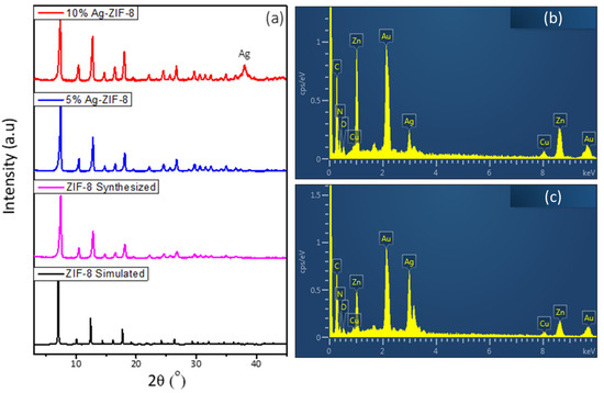
Figure 1.
(a) The XRD of ZIF-8 and Ag-ZIF-8, (b) the EDX of 5% Ag-ZIF-8, (c) the EDX of 10% Ag-ZIF-8.
The morphological and structural properties of the prepared material were investigated by the SEM. Figure 2a shows the SEM of ZIF-8, which reveals uniform dodecahedron crystals. In comparison of ZIF-8 with the Ag-loaded sample, there was no significant difference in the morphology and no agglomeration of Ag nanoparticles was observed. The SEM results were supported after carrying out the TEM (Figure 2g–i). The TEM showed uniform crystals corresponding to the ZIF-8 frame work. In the high-resolution image, no Ag particles agglomerated were observed on the surface of the MOF. The elemental mapping (Figure 3) confirmed the uniform dispersion of the elements (C, N, Zn, O, and Ag). The phase of Zn in the ZIF-8 was Zn2+ due to its binding with the nitrogen atoms in the organic imidazole linkers, while the doped Ag phase was metallic within the framework as confirmed by XRD, and had no covalent bond with the organic linker or the metal node in the framework. These results were also supported by XPS analysis [34,36,37].
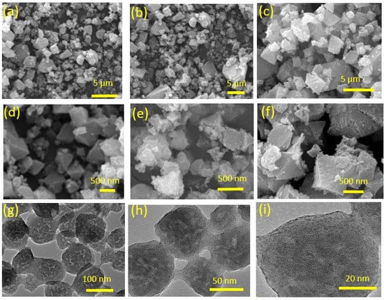
Figure 2.
SEM of (a,d) ZIF-8, (b,e) 5% Ag-ZIF-8, and (c,f) 10% Ag-ZIF-8. TEM of (g–i) 10% Ag-ZIF-8.
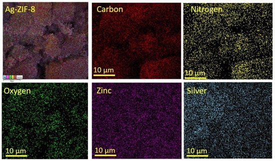
Figure 3.
The elemental mapping of 10% Ag-ZIF-8.
The surface area of the ZIF-8 and Ag-ZIF-8 was investigated with the aid of the BET surface analyzer (Figure 4a). The pristine ZIF-8 showed a high surface area characteristic of most MOFs, which is about 1500 m2 g−1. Upon the loading of the silver nanoparticles, a decrease in the surface area was observed to ~1200 and 1000 m2 g−1 for 5% Ag-ZIF-8 and 10% Ag-ZIF-8, respectively, which further confirmed the loading of the nanoparticles into the framework of the ZIF-8, as shown in Figure 4a. Moreover, FTIR was carried out for ZIF-8, 5% Ag-ZIF-8, and 10% Ag-ZIF-8, revealing identical IR spectra as shown in Figure 4b. The peak for 2-methylimidazole (MeIm) was seen at 694 cm−1 (C-H bend).
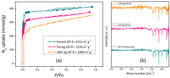
Figure 4.
(a) BET isotherm of ZIF-8, 5% Ag-ZIF-8, and 10% Ag-ZIF-8; (b) FTIR spectra of ZIF-8, 5% Ag-ZIF-8 and 10% Ag-ZIF-8.
The in-plane deformation vibration of (=C-H) was confirmed by the peak at 1147 cm−1. The CH2 wagging transmits light at 1313 cm−1, and the =C-H in-plane bending happens at 995 cm−1. Both CH3 and CH2 responded at 1384 cm−1 and 1427 cm−1, respectively, due to their asymmetric bends. Stretches of the carbon–carbon double bond (C=C stretch) and the carbon-nitrogen double bond (C=N stretch) had peaks at 1456 cm−1 and 1585 cm−1, respectively. The (C-H) symmetric stretch and (=C-H) stretch were both confirmed by the two tiny narrow peaks at 2931 cm−1 and 3137 cm−1, respectively. The IR spectra in Figure 4b confirm the preservation of the framework even after Ag loading [38], which further supports the XRD results.
In order to demonstrate the overall electrocatalytic performance, the electrocatalysts (ZIF-8, 5% Ag-ZIF-8, 10% Ag-ZIF-8) were analyzed using linear sweep voltammetry (LSV) in N2- or CO2-saturated 0.1 M KHCO3 electrolytes (Figure 5a). The faradaic currents found in an N2-saturated electrolyte are inextricably linked to the hydrogen evolution reaction (HER), whereas the faradaic currents in the presence of CO2 are ascribed to contributions from both the HER and CO2RR. In all cases, the CO2-saturated electrolyte exhibited higher current densities than the N2-saturated electrolyte. It can be observed clearly that pristine ZIF-8 showed the lowest current density. Upon the loading of the ZIF-8 with 5% Ag, the current density increased significantly (from 5 to 10 mA cm−2). The current density also increased with a greater Ag loading of 10% to 14.5 mA cm−2.
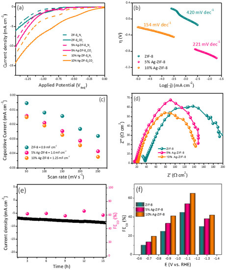
Figure 5.
(a) The polarization curves of ZIF-8, 5% Ag-ZIF-8, and 10% Ag-ZIF-8 in N2 and CO2-saturated 0.1 M KHCO3. (b) Tafel slope of ZIF-8, 5% Ag-ZIF-8, 10% Ag-ZIF-8. (c) Cdl slopes of ZIF-8, 5% Ag-ZIF-8, and 10% Ag-ZIF-8. (d) Nyquist plots of ZIF-8, 5% Ag-ZIF-8, and 10% Ag-ZIF-8 (e) chronoamperometry of 10% Ag-ZIF-8 in CO2-saturated 0.1 M KHCO3. (f) FE of ZIF-8, 5% Ag-ZIF-8, and 10% Ag-ZIF-8 in CO2-saturated 0.1 M KHCO3.
To gain insight about the mechanism and the kinetics of the ECO2RR, the Tafel slope was estimated from the polarization curves (Figure 5b). Tafel values of 420, 221, and 154 mV dec−1 were calculated for the electrodes ZIF-8, 5% Ag-ZIF-8, and 10% Ag-ZIF-8, respectively. The lowest Tafel slope value suggests faster reaction kinetics and facilitated adsorption of the CO2•− intermediate [39].
Another important factor is the electrochemical active surface area (ESCA), which can be estimated from the double-layer capacitance (Cdl). The Cdl was evaluated by recording cyclic voltammograms (Figure S2) at different scan rates (50, 100, 150, 200, and 250 mV s−1) and plotting the capacitive current vs. the scan rate. As shown in Figure 5c, 10% Ag-ZIF-8 exhibited the highest Cdl value (1.25 mF), followed by 5% Ag-ZIF-8 (1.00 mF), and the pristine ZIF-8 showed the lowest Cdl value (0.90 mF). Electrochemical impedance spectroscopy (EIS) was used to study the interaction between the electrode and electrolyte interface through charge transfer resistance (Rct), which was obtained from Nyquist plot [40] (Figure 5d). The high frequency is ascribed to the CO2RR to CO (mass transport), whereas the low frequency could be related to the electrolysis process (HER). The Rct values were 205, 148, and 140 Ω cm2 for the electrodes ZIF-8, 5% Ag-ZIF-8, and 10% Ag-ZIF-8, respectively. It can be seen that doping the ZIF-8 with Ag enhances the charge transfer rate dramatically, and the 10% loading showed the lowest Rct.
The electrode durability was investigated using chronoamperometry (Figure 5e) in 0.1 M KHCO3. The long-term current time curve revealed a good stability for 16 h. The electrochemical performance toward CO2 reduction was investigated for the three electrodes (ZIF-8, 5% Ag-ZIF-8, and 10% Ag-ZIF-8) using the chronoamperometry at different applied potentials for 1 h and the products were quantified using online connected GC-BID. The CO faradic efficiency (FE) of the electrodes is compared in Figure 5f. The three electrocatalysts showed a similar trend in the CO production. At low applied potential, a low CO yield was observed. Increasing the potential led to a significant increase in the CO FE%. The applied potential –1.1 VRHE exhibited the highest FE%. A further increase in potential led to a decrease in the FE%. The lower CO FEs at greater negative potentials (–1.3 V versus RHE) may result from the limited CO2 and polarization losses. The applied voltage increased the current densities of the electrocatalysts, the CO FE gradually reduced, and the CO current densities remained constant due to the competing HER on the electrode surface, which is consistent with the results reported previously. The 5% Ag-ZIF-8 showed higher FE% than the ZIF-8 at these applied potentials. The 10% Ag-ZIF-8 showed the highest FE (70% for CO and 30% for H2) at −1.1 V.
The optimized electrode (10% Ag-ZIF-8) in the H-cell was also investigated in the flow cell system, which is a more practical setup. The LSV and FE obtained from the flow cell were compared with the results obtained from the H-cell. As can be observed in Figure 6a, the current density in the flow cell was significantly higher than that in the H-cell. This can be attributed to the GDE, which allows the diffusion of more CO2 gas into the catalyst surface. Additionally, the flow system provides fresh electrolyte to the electrode surface, which facilitates the overall reaction. Since the electrolyte compartments in the flow system are separated, unlike the H-cell, two different electrolytes can be used. KOH in the anolyte serves as a proton source due to the oxygen evolution reaction in the anode, which is more efficient than KHCO3. The FE% trend was different in the case of the flow cell. The highest FE% values (69.0 and 80%) were observed at relatively lower potentials (–0.7 and –0.9 VRHE). Moreover, when the FEs were compared (Figure 6b,c), the flow cell showed higher conversion rate at lower applied potential (80% at −0.9 VRHE) compared to (70% at –1.1 VRHE) for the H-cell. In addition to the higher FE in the flow cell, its higher efficiency can be noted by calculating the partial current density (the current utilized in the CO2 conversion). As shown in Figure 6d, the current was almost 5 times the one used in the H-cell.
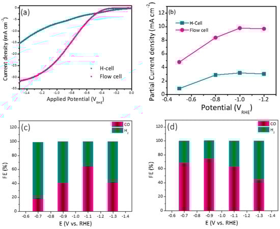
Figure 6.
(a) Comparative LSV for 10% Ag-ZIF-8 using an H-cell and flow cell. (b) The partial current density for 10% Ag-ZIF-8 using the H-cell and the flow cell and the FE using (c) the H-cell (d) the flow cell.
The electrochemical performance and conversion efficiency of the current findings are shown in (Table 1), which compares Ag-based, ZIF-8, and Ag-ZIF-8 composites for the electroreduction of CO2 into usable liquid chemicals. The 10% Ag-ZIF-8 produced syngas with a FE% ratio of 70:30 (CO:H2) at a potential of −1.1 V vs. RHE and 80:20 at a potential of −0.9 V vs. RHE, which is a marked improvement over previous reports.

Table 1.
Comparison of the catalytic performances of 10% Ag-ZIF-8 and the similar electrocatalysts reported in literature for the reduction of CO2.
3. Experimental
3.1. Materials
Zinc nitrate (ZnNO3) (99.95%), silver nitrate (AgNO3), ascorbic acid (99.0%) 2-methyl imidazole (99.0%), potassium bicarbonate (99.9), and potassium hydroxide(99.5%) were purchased from Sigma Aldrich, St. Louis, MO, USA. Methanol (CH3OH) (99.8%) was procured from Sharlu (Sharjah, United Arab Emirates).
3.2. Preparation of ZIF-8
ZIF-8 was prepared according to the procedure reported by Lee et al. [45]. Briefly, 1.31 g of Zn(NO3)2 was dissolved in 45 mL of methanol in a 100 mL beaker. In another beaker, 2.87 g of 2-methyl imidazole was dissolved until a clear solution appeared. The two clear solutions were mixed in a 150 mL round bottom flask and stirred at room temperature for 1 h. The synthesized white ZIF-8 suspension was separated by centrifugation at 8000 rpm for 10 min. The white crystal was washed three times with methanol.
3.3. Preparation of Silver Nanoparticles Decorated on ZIF-8
The 5% Ag-ZIF-8 was prepared as follows (as shown in Figure 7). Briefly, 10 mg of silver nitrate (AgNO3) was dissolved in 20 mL of methanol, then 100 mg the as-prepared ZIF-8 was added to the solution. The solution was sonicated for 10 min and stirred for 2 h. The white crystals were separated and washed with methanol three times to remove the surface Ag+. The crystals were re-dispersed in 20 mL methanol and 20 mg of ascorbic acid was added and the solution was stirred for 30 min. Then, the crystals were separated and washed several times with DI water and methanol and dried at 50 °C under vacuum for 5 h.
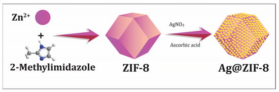
Figure 7.
The schematic presentation of the synthesis of Ag-doped ZIF-8 particles.
3.4. Preparation of the Electrocatalyst
3.4.1. Electrode Fabrication of H-Cell
Ten milligrams of the ZIF-8 or Ag-ZIF-8 catalyst was dispersed in 1 mL mixture of 750 µL isopropanol, 200 µL DI water, and 50 µL Nafion (5%). The mixture was sonicated for 20 min. Then, 100 µL of the suspension was drop-cast onto 1 cm2 conductive carbon paper and dried at room temperature.
3.4.2. Electrode Fabrication of Flow Cell
The spray painting method was applied to prepare the working electrodes for the flow cell. This process is efficient and cost-effective for creating gas diffusion electrode (GDE) with superior electrochemical performance. Twenty milligrams of the ZIF-8 or Ag-ZIF-8 catalyst was dispersed in a 2 mL mixture of 1500 µL isopropanol, 400 µL DI water, and 100 µL Nafion (5%). The mixture was homogenized using a magnetic stirrer or ultrasonication. Next, 200 µL of the prepared ink was kept under constant air flow and pressure and sprayed on GDE using the spray gun method. Using a high-pressure air spray gun, the catalyst ink was sprayed onto the carbon support material’s surface. The spray nozzle is normally operated at 1.5 to 3 bar of pressure, with a 2 to 5 cm gap between it and the GDE. The GDE coated with the catalyst ink was then dried for 30 to 60 min at a temperature of 60 to 80 °C before its application in the flow cell.
3.5. Characterization
Morphological and detailed microstructural attributes of the materials were discerned by field emission scanning electron microscopy (FESEM, Tescan Lyra-3, Kohoutovice, Czech Republic). The sample was gold-coated for 30 s before SEM and EDS analysis. Another technique employed for the characterization of the samples was X-ray diffraction (XRD, Rigaku MiniFlex, Austin, TX, USA) to reveal the crystal structure of the materials. To begin, the samples were finely powdered using a mill and pestle to ensure consistency and remove any big pieces. The next step was to put the powdered samples into a sample holder. The sample was then prepared for analysis by having its surface flattened and leveled using a glass slide. This helps to ensure that reliable results are obtained. After that, the sample holder was transferred into the XRD machine, and the analysis commenced. The obtained XRD was matched with the simulated XRD of the materials. Fourier-transform infrared (FT-IR Thermo, Waltham, MA, USA) was used to identify the functional groups in the materials. BET surface analyzer (Triplex) was used to calculate the porous nature of a material. This method is based on gas adsorption as a function of pressure. Typically the sample is first degassed at 120 °C for 6 h. Under a nitrogen environment, the gas pressure is measured vs. the amount of gas adsorbed by the sample to calculate the porosity. A gas chromatographer (GC) equipped with barrier ion discharge detector (Shimadzu, Kyoto, Japan), and potentiostat (Gammray 620, Warminster, UK) were used.
3.6. The Electrochemical Studies
The ECO2RR performance was investigated with the aid of H-cell and flow cell systems. The H-cell consisted of a silver silver-chloride electrode (Ag/AgCl) as a reference electrode. A platinum mesh was used as a counter electrode. As-prepared Cu-NP@NC film on conductive carbon paper was used as the working electrode. A potentiostat (Gammray 620) was connected to the electrodes in the cell.
The flow cell setup consisted of three main components. The first one was the electrolyte compartments, one compartment containing the catholyte, which was 0.5 M KHCO3, and the second compartment containing the anolyte, which was 1.0 M KOH. The second component was the cell, which consisted of the cathode part (where the CO2 gas passes on one side of the GDE and the catholyte passes on the other side) and the anode part connected to the anolyte. The two parts of the cell were separated by a proton permeable membrane to allow the produced H+ to pass from the anode to the cathode. The third component of the flow cell was the pump, which controlled flows and circulated the catholyte and anolyte between the electrolyte compartments to the cell. Similar to the H-cell, the reference electrode was connected with working electrode (GDE) on the cathode side and counter electrode on the anode side and all were connected to a potentiostat workstation (Gammray 620).
The ECO2RR performance was evaluated by carrying out linear sweep voltammetry (LSV) techniques, and calculation of the overpotential at different current densities (current normalized to the geometric surface area of the electrode). The cyclic voltammetry (CV) and LSV experiments were performed in 0.1 M potassium bicarbonate (KHCO3).
where [46].
The potential was swept from (0.0 to –1.4 V vs. RHE). The electrochemical impedance spectroscopy (EIS) was performed by varying the frequency from 105 to 0.1 Hz under identical electrolyte and electrodes to the LSV.
4. Conclusions
In conclusion, we prepared silver-doped ZIF-8 (Ag@ZIF-8) that acted as a good catalyst for the production of syngas (CO and H2) at various loading and at various potentials. The experimental findings show that Ag-doped ZIF materials had a higher current density than ZIF-8. Furthermore, the flow cell had a higher current density than the H-cell. The product analysis revealed 100% FE for the gas products. Based on qualitative and quantitative analyses, the products contained syngas at various ratios of H2 and CO, and could be influenced by the applied potential. These findings reveal that the Ag-ZIF-8 platform offers promising materials for effective CO2 conversion to syngas.
Supplementary Materials
The following supporting information can be downloaded at https://www.mdpi.com/article/10.3390/catal13050867/s1, Figure S1: (a) EDX of 5% Ag-ZIF-8 and (b) 10% Ag-ZIF-8; Figure S2: CVs of (a) ZIF-8, (b) 5% Ag-ZIF-8 and (c) 10% Ag-ZIF-8 at scan rates of 50, 100, 150, 200 and 250 mV s−1.
Author Contributions
Conceptualization, M.U., and M.H.S.; methodology, M.U. and M.H.S.; investigation, M.U.; resources, M.U. and M.H.S.; writing—original draft preparation, M.U.; writing—review and editing, M.U., and M.H.S.; supervision, M.U.; formal analysis, M.U., and M.H.S.; funding acquisition, M.U. All authors have read and agreed to the published version of the manuscript.
Funding
This research was funded by King Fahd University of Petroleum and Minerals: ORCP2390.
Data Availability Statement
The data can be found in the main text and Supplementary Materials.
Acknowledgments
We acknowledge the Interdisciplinary Research Center for Hydrogen and Energy Storage (IRC-HES) for its continued support. The Saudi Aramco Chair Professor Project at KFUPM ORCP2390 supported this research.
Conflicts of Interest
The authors declare no conflict of interest.
References
- Jahangiri, H.; Bennett, J.; Mahjoubi, P.; Wilson, K.; Gu, S. A review of advanced catalyst development for Fischer–Tropsch synthesis of hydrocarbons from biomass derived syn-gas. Catal. Sci. Technol. 2014, 4, 2210–2229. [Google Scholar] [CrossRef]
- Sattarzadeh, M.; Ebrahimi, M.; Jazayeri, S.A. A detail study of a RCCI engine performance fueled with diesel fuel and natural gas blended with syngas with different compositions. Int. J. Hydrogen Energy 2022, 47, 16283–16296. [Google Scholar] [CrossRef]
- Mohanty, U.S.; Ali, M.; Azhar, M.R.; Al-Yaseri, A.; Keshavarz, A.; Iglauer, S. Current advances in syngas (CO + H2) production through bi-reforming of methane using various catalysts: A review. Int. J. Hydrogen Energy 2021, 46, 32809–32845. [Google Scholar] [CrossRef]
- Garba, M.D.; Usman, M.; Khan, S.; Shehzad, F.; Galadima, A.; Ehsan, M.F.; Ghanem, A.S.; Humayun, M. CO2 towards fuels: A review of catalytic conversion of carbon dioxide to hydrocarbons. J. Environ. Chem. Eng. 2021, 9, 104756. [Google Scholar] [CrossRef]
- Li, M.; Irtem, E.; Iglesias van Montfort, H.-P.; Abdinejad, M.; Burdyny, T. Energy comparison of sequential and integrated CO2 capture and electrochemical conversion. Nat. Commun. 2022, 13, 5398. [Google Scholar] [CrossRef] [PubMed]
- Joshi, G.; Pandey, J.K.; Rana, S.; Rawat, D.S. Challenges and opportunities for the application of biofuel. Renew. Sustain. Energy Rev. 2017, 79, 850–866. [Google Scholar] [CrossRef]
- Usman, M.; Humayun, M.; Garba, M.D.; Ullah, L.; Zeb, Z.; Helal, A.; Suliman, M.H.; Alfaifi, B.Y.; Iqbal, N.; Abdinejad, M.; et al. Electrochemical Reduction of CO2: A Review of Cobalt Based Catalysts for Carbon Dioxide Conversion to Fuels. Nanomaterials 2021, 11, 2029. [Google Scholar] [CrossRef]
- Usman, M.; Li, D.; Li, C.; Zhang, S. Highly selective and stable hydrogenation of heavy aromatic-naphthalene over transition metal phosphides. Sci. China Chem. 2015, 58, 738–746. [Google Scholar] [CrossRef]
- Masel, R.I.; Liu, Z.; Yang, H.; Kaczur, J.J.; Carrillo, D.; Ren, S.; Salvatore, D.; Berlinguette, C.P. An industrial perspective on catalysts for low-temperature CO2 electrolysis. Nat. Nanotechnol. 2021, 16, 118–128. [Google Scholar] [CrossRef]
- Usman, M.; Iqbal, N.; Noor, T.; Zaman, N.; Asghar, A.; Abdelnaby, M.M.; Galadima, A.; Helal, A. Advanced strategies in Metal-Organic Frameworks for CO2 Capture and Separation. Chem. Rec. 2022, 22, e202100230. [Google Scholar] [CrossRef]
- Trickett, C.A.; Helal, A.; Al-Maythalony, B.A.; Yamani, Z.H.; Cordova, K.E.; Yaghi, O.M. The chemistry of metal–organic frameworks for CO2 capture, regeneration and conversion. Nat. Rev. Mater. 2017, 2, 17045. [Google Scholar] [CrossRef]
- Usman, M.; Zeb, Z.; Ullah, H.; Suliman, M.H.; Humayun, M.; Ullah, L.; Shah, S.N.A.; Ahmed, U.; Saeed, M. A review of metal-organic frameworks/graphitic carbon nitride composites for solar-driven green H2 production, CO2 reduction, and water purification. J. Environ. Chem. Eng. 2022, 10, 107548. [Google Scholar] [CrossRef]
- Usman, M.; Helal, A.; Abdelnaby, M.M.; Alloush, A.M.; Zeama, M.; Yamani, Z.H. Trends and Prospects in UiO-66 Metal-Organic Framework for CO2 Capture, Separation, and Conversion. Chem. Rec. 2021, 21, 1771–1791. [Google Scholar] [CrossRef] [PubMed]
- Ghanem, A.S.; Ba-Shammakh, M.; Usman, M.; Khan, M.F.; Dafallah, H.; Habib, M.A.; Al-Maythalony, B.A. High gas permselectivity in ZIF-302/polyimide self-consistent mixed-matrix membrane. J. Appl. Polym. Sci. 2020, 137, 48513. [Google Scholar] [CrossRef]
- Helal, A.; Sanhoob, M.A.; Hoque, B.; Usman, M.; Zahir, M.H. Bimetallic Metal-Organic Framework Derived Nanocatalyst for CO2 Fixation through Benzimidazole Formation and Methanation of CO2. Catalysts 2023, 13, 357. [Google Scholar] [CrossRef]
- Helal, A.; Cordova, K.E.; Arafat, M.E.; Usman, M.; Yamani, Z.H. Defect-engineering a metal–organic framework for CO2 fixation in the synthesis of bioactive oxazolidinones. Inorg. Chem. Front. 2020, 7, 3571–3577. [Google Scholar] [CrossRef]
- Sekine, K.; Yamada, T. Silver-catalyzed carboxylation. Chem. Soc. Rev. 2016, 45, 4524–4532. [Google Scholar] [CrossRef]
- Abdinejad, M.; Ferrag, C.; Hossain, M.N.; Noroozifar, M.; Kerman, K.; Kraatz, H.B. Capture and electroreduction of CO2 using highly efficient bimetallic Pd–Ag aerogels paired with carbon nanotubes. J. Mater. Chem. A 2021, 9, 12870–12877. [Google Scholar] [CrossRef]
- Abdinejad, M.; Irtem, E.; Farzi, A.; Sassenburg, M.; Subramanian, S.; Iglesias van Montfort, H.-P.; Ripepi, D.; Li, M.; Middelkoop, J.; Seifitokaldani, A.; et al. CO2 Electrolysis via Surface-Engineering Electrografted Pyridines on Silver Catalysts. ACS Catal. 2022, 12, 7862–7876. [Google Scholar] [CrossRef]
- Abdinejad, M.; Santos da Silva, I.; Kraatz, H.B. Electrografting amines onto silver nanoparticle-modified electrodes for electroreduction of CO2 at low overpotential. J. Mater. Chem. A 2021, 9, 9791–9797. [Google Scholar] [CrossRef]
- Shi, J.; Zhang, L.; Sun, N.; Hu, D.; Shen, Q.; Mao, F.; Gao, Q.; Wei, W. Facile and Rapid Preparation of Ag@ZIF-8 for Carboxylation of Terminal Alkynes with CO2 in Mild Conditions. ACS Appl. Mater. Interfaces 2019, 11, 28858–28867. [Google Scholar] [CrossRef] [PubMed]
- Wu, J.-K.; Tan, P.; Lu, J.; Jiang, Y.; Liu, X.-Q.; Sun, L.-B. Fabrication of Photothermal Silver Nanocube/ZIF-8 Composites for Visible-Light-Regulated Release of Propylene. ACS Appl. Mater. Interfaces 2019, 11, 29298–29304. [Google Scholar] [CrossRef]
- Chen, J.; Gu, A.; Miensah, E.D.; Liu, Y.; Wang, P.; Mao, P.; Gong, C.; Jiao, Y.; Chen, K.; Zhang, Z.; et al. Silver-decorated ZIF-8 derived ZnO concave nanocubes for efficient photooxidation-adsorption of iodide anions: An in-depth experimental and theoretical investigation. J. Solid State Chem. 2021, 297, 122039. [Google Scholar] [CrossRef]
- Hori, Y.; Ito, H.; Okano, K.; Nagasu, K.; Sato, S. Silver-coated ion exchange membrane electrode applied to electrochemical reduction of carbon dioxide. Electrochim. Acta 2003, 48, 2651–2657. [Google Scholar] [CrossRef]
- Hoshi, N.; Kato, M.; Hori, Y. Electrochemical reduction of CO2 on single crystal electrodes of silver Ag(111), Ag(100) and Ag(110). J. Electroanal. Chem. 1997, 440, 283–286. [Google Scholar] [CrossRef]
- Hatsukade, T.; Kuhl, K.P.; Cave, E.R.; Abram, D.N.; Jaramillo, T.F. Insights into the electrocatalytic reduction of CO2 on metallic silver surfaces. Phys. Chem. Chem. Phys. 2014, 16, 13814–13819. [Google Scholar] [CrossRef]
- Daiyan, R.; Lu, X.; Ng, Y.H.; Amal, R. Highly Selective Conversion of CO2 to CO Achieved by a Three-Dimensional Porous Silver Electrocatalyst. ChemistrySelect 2017, 2, 879–884. [Google Scholar] [CrossRef]
- Jiang, X.; Wu, H.; Chang, S.; Si, R.; Miao, S.; Huang, W.; Li, Y.; Wang, G.; Bao, X. Boosting CO2 electroreduction over layered zeolitic imidazolate frameworks decorated with Ag2O nanoparticles. J. Mater. Chem. A 2017, 5, 19371–19377. [Google Scholar] [CrossRef]
- Yan, S.; Chen, C.; Zhang, F.; Mahyoub, S.A.; Cheng, Z. High-density Ag nanosheets for selective electrochemical CO2 reduction to CO. Nanotechnology 2021, 32, 165705. [Google Scholar] [CrossRef]
- Lu, Q.; Rosen, J.; Zhou, Y.; Hutchings, G.S.; Kimmel, Y.C.; Chen, J.G.; Jiao, F. A selective and efficient electrocatalyst for carbon dioxide reduction. Nat. Commun. 2014, 5, 3242. [Google Scholar] [CrossRef]
- Liu, M.; Liu, M.; Wang, X.; Kozlov, S.M.; Cao, Z.; De Luna, P.; Li, H.; Qiu, X.; Liu, K.; Hu, J.; et al. Quantum-Dot-Derived Catalysts for CO2 Reduction Reaction. Joule 2019, 3, 1703–1718. [Google Scholar] [CrossRef]
- Wang, Y.; Hou, P.; Wang, Z.; Kang, P. Zinc Imidazolate Metal–Organic Frameworks (ZIF-8) for Electrochemical Reduction of CO2 to CO. Chemphyschem 2017, 18, 3142–3147. [Google Scholar] [CrossRef] [PubMed]
- Suliman, M.H.; Baroud, T.N.; Siddiqui, M.N.; Qamar, M.; Giannelis, E.P. Confined growth and dispersion of FeP nanoparticles in highly mesoporous carbons as efficient electrocatalysts for the hydrogen evolution reaction. Int. J. Hydrogen Energy 2021, 46, 8507–8518. [Google Scholar] [CrossRef]
- Pan, Y.; Liu, Y.; Zeng, G.; Zhao, L.; Lai, Z. Rapid synthesis of zeolitic imidazolate framework-8 (ZIF-8) nanocrystals in an aqueous system. Chem. Commun. 2011, 47, 2071–2073. [Google Scholar] [CrossRef]
- Khani, M.; Sammynaiken, R.; Wilson, L.D. Electrocatalytic Oxidation of Nitrophenols via Ag Nanoparticles Supported on Citric-Acid-Modified Polyaniline. Catalysts 2023, 13, 465. [Google Scholar] [CrossRef]
- Veeramani, V.; Van Chi, N.; Yang, Y.-L.; Hong Huong, N.T.; Van Tran, T.; Ahamad, T.; Alshehri, S.M.; Wu, K.C.W. Decoration of silver nanoparticles on nitrogen-doped nanoporous carbon derived from zeolitic imidazole framework-8 (ZIF-8) via in situ auto-reduction. RSC Adv. 2021, 11, 6614–6619. [Google Scholar] [CrossRef] [PubMed]
- Tian, F.; Cerro, A.M.; Mosier, A.M.; Wayment-Steele, H.K.; Shine, R.S.; Park, A.; Webster, E.R.; Johnson, L.E.; Johal, M.S.; Benz, L. Surface and Stability Characterization of a Nanoporous ZIF-8 Thin Film. J. Phys. Chem. C 2014, 118, 14449–14456. [Google Scholar] [CrossRef]
- Ahmad, A.; Iqbal, N.; Noor, T.; Hassan, A.; Khan, U.A.; Wahab, A.; Raza, M.A.; Ashraf, S. Cu-doped zeolite imidazole framework (ZIF-8) for effective electrocatalytic CO2 reduction. J. CO2 Util. 2021, 48, 101523. [Google Scholar] [CrossRef]
- Hu, C.; Bai, S.; Gao, L.; Liang, S.; Yang, J.; Cheng, S.-D.; Mi, S.-B.; Qiu, J. Porosity-Induced High Selectivity for CO2 Electroreduction to CO on Fe-Doped ZIF-Derived Carbon Catalysts. ACS Catal. 2019, 9, 11579–11588. [Google Scholar] [CrossRef]
- Suliman, M.H.; Yamani, Z.H.; Usman, M. Electrochemical Reduction of CO2 to C1 and C2 Liquid Products on Copper-Decorated Nitrogen-Doped Carbon Nanosheets. Nanomaterials 2023, 13, 47. [Google Scholar] [CrossRef]
- Jiang, X.; Li, H.; Xiao, J.; Gao, D.; Si, R.; Yang, F.; Li, Y.; Wang, G.; Bao, X. Carbon dioxide electroreduction over imidazolate ligands coordinated with Zn(II) center in ZIFs. Nano Energy 2018, 52, 345–350. [Google Scholar] [CrossRef]
- Dou, S.; Song, J.; Xi, S.; Du, Y.; Wang, J.; Huang, Z.-F.; Xu, Z.J.; Wang, X. Boosting Electrochemical CO2 Reduction on Metal–Organic Frameworks via Ligand Doping. Angew. Chem. Int. Ed. 2019, 58, 4041–4045. [Google Scholar] [CrossRef]
- Kim, B.; Ma, S.; Molly Jhong, H.-R.; Kenis, P.J.A. Influence of dilute feed and pH on electrochemical reduction of CO2 to CO on Ag in a continuous flow electrolyzer. Electrochim. Acta 2015, 166, 271–276. [Google Scholar] [CrossRef]
- Li, Y.C.; Zhou, D.; Yan, Z.; Gonçalves, R.H.; Salvatore, D.A.; Berlinguette, C.P.; Mallouk, T.E. Electrolysis of CO2 to Syngas in Bipolar Membrane-Based Electrochemical Cells. ACS Energy Lett. 2016, 1, 1149–1153. [Google Scholar] [CrossRef]
- Lee, Y.-R.; Jang, M.-S.; Cho, H.-Y.; Kwon, H.-J.; Kim, S.; Ahn, W.-S. ZIF-8: A comparison of synthesis methods. Chem. Eng. J. 2015, 271, 276–280. [Google Scholar] [CrossRef]
- Wang, Y.; Niu, C.; Zhu, Y. Copper–Silver Bimetallic Nanowire Arrays for Electrochemical Reduction of Carbon Dioxide. Nanomaterials 2019, 9, 173. [Google Scholar] [CrossRef]


Disclaimer/Publisher’s Note: The statements, opinions and data contained in all publications are solely those of the individual author(s) and contributor(s) and not of MDPI and/or the editor(s). MDPI and/or the editor(s) disclaim responsibility for any injury to people or property resulting from any ideas, methods, instructions or products referred to in the content. |
© 2023 by the authors. Licensee MDPI, Basel, Switzerland. This article is an open access article distributed under the terms and conditions of the Creative Commons Attribution (CC BY) license (https://creativecommons.org/licenses/by/4.0/).