Review

Organic Semiconductor-Based Photoelectrochemical Cells for Efficient Solar-to-Chemical Conversion

1
School of Energy and Chemical Engineering, Ulsan National Institute of Science and Technology (UNIST), Ulsan 44919, Republic of Korea
2
Emergent Hydrogen Technology R&D Center, Ulsan National Institute of Science and Technology (UNIST), Ulsan 44919, Republic of Korea
3
Graduate School of Carbon Neutrality, Ulsan National Institute of Science and Technology (UNIST), Ulsan 44919, Republic of Korea
*
Author to whom correspondence should be addressed.
Catalysts 2023, 13(5), 814; https://doi.org/10.3390/catal13050814
Submission received: 5 April 2023 / Revised: 25 April 2023 / Accepted: 25 April 2023 / Published: 27 April 2023
(This article belongs to the Special Issue Theme Issue in Honor of Prof. Dr. Jae Sung Lee)

Abstract

:
Organic semiconductor-based photoelectrodes are gaining significant attention in photoelectrochemical (PEC) value-added chemical production systems, which are promising architectures for solar energy harvesting. Organic semiconductors consisting of conjugated carbon–carbon bonds provide several advantages for PEC cells, including improved charge transfer, tunable band positions and band gaps, low cost, and facile fabrication using organic solvents. This review gives an overview of the recent advances in emerging single organic semiconductor-based photoelectrodes for PEC water splitting and the various strategies for enhancing their performance and stability. It highlights the importance of photoelectrodes based on donor–acceptor bulk heterojunction (BHJ) systems for fabricating efficient organic semiconductor-based solar energy-harvesting devices. Furthermore, it evaluates the recent progress in BHJ organic base photoelectrodes for producing highly efficient PEC value-added chemicals, such as hydrogen and hydrogen peroxide. Finally, this review highlights the potential of organic-based photoelectrodes for bias-free solar-to-chemical production, which is the ultimate goal of PEC systems and a step toward achieving reliable commercial technology.

Graphical Abstract

1. Introduction

Solar energy is a promising next-generation energy source for replacing fossil fuels because of its unlimited availability and sustainable characteristics [1,2]. To efficiently harvest solar energy, its conversion to chemical fuels is necessary to facilitate storage, transportation, and application at various industrial sites [3]. In particular, hydrogen (H2), generated by solar-driven water electrolysis, is a vital eco-friendly energy carrier for a carbon-neutral economy. H2 can be converted easily to electricity with a high specific mass-energy density (140 MJ kg−1) and no carbon dioxide emission [4,5,6,7]. Furthermore, solar H2 production technology has contributed significantly to resolving global energy inequality owing to the abundant sunlight and water resources worldwide. Accordingly, there has been active developmental progress in photoelectrochemical (PEC) water-splitting cells, which are among the most promising architectures for green H2 production systems [8,9]. The design of PEC water-splitting cells requires a photoelectrode, a photoabsorbing semiconductor-based electrode for oxidation or reduction reactions [10]. For achieving a high-performance PEC cell, it is necessary for the semiconductor materials in the photoelectrode to have conduction and valence band levels that are more negative than the hydrogen evolution reaction (HER) potential (0 V vs. normal hydrogen electrode (NHE)) and more positive than the oxygen evolution reaction (OER) potential (1.23 V vs. NHE) [11]. Furthermore, to achieve efficient PEC water splitting, the material should possess an appropriate band gap of approximately 1.6 [11]. Since the first demonstration of PEC water splitting with a titanium dioxide (TiO2) photoanode in 1972 [12], there has been significant research on inorganic semiconductor-based photoelectrodes, especially transition metal oxides such as BiVO4, Fe2O3, WO3, and Cu2O [13,14,15,16,17,18,19,20,21,22,23,24,25,26,27,28,29,30]. Despite extensive research, no inorganic semiconductors have yet been developed that fully satisfy the requirements for efficient photoelectrochemical (PEC) water splitting, including appropriate band positions and band gaps, as well as high charge transport properties. In addition, these band positions and band gaps of inorganic materials are not tunarable. As a result, the performance of these materials still falls short of the practical criteria for PEC water splitting. Specifically, for PEC water splitting to be practical, the solar-to-hydrogen conversion efficiency (STH) must be at least 10%, corresponding to a photocurrent density of around 8.13 mA cm−2. However, current inorganic semiconductor materials have not yet achieved these performance levels.
In recent years, organic semiconductors comprising conjugated carbon (C)-C bonds have attracted attention as photoelectrode materials for PEC water-splitting cells. They possess several advantages, including superior charge-transfer characteristics, the flexibility of band positions and band gaps, low cost, and high solubility in organic solvents, which facilitate simple fabrication methods [31,32,33]. In particular, superior charge transport mobility, appropriate band positions, and optimal band gaps of photoabsorbing semiconductors directly influence the performance of PEC systems. This is apparent in the photovoltage of the photoelectrode, reaction kinetics, and the broad absorption range of solar light harvesting. Therefore, organic semiconductor-based photoelectrodes exhibit potential concerning commercial PEC H2 production. By adjusting the level of the highest occupied molecular orbital (HOMO) and the lowest unoccupied molecular orbital (LUMO) of the light-absorbing materials, these photoelectrodes can be optimized easily for solar water splitting [34,35]. Furthermore, the bulk heterojunction (BHJ) architecture, which utilizes a blend of conjugated polymers and small molecules, is one of the most promising strategies for fabricating efficient organic photoelectrodes. This approach has already been widely adopted to enhance the performance of organic PVs (OPVs) and has various merits such as efficient photo-generated charge separation by reducing the charge recombination, ease of tuning the photovoltage with simple material selection, and wide range of light absorption [36,37]. In addition, the feasibility of solution processing is a crucial characteristic for fabricating large-area photoelectrodes using inkjet printing and slot-die coating techniques under ambient conditions [38,39]. The PEC systems with organic semiconductors comprise a structure in which an organic semiconductor, charge extraction layer, or cocatalyst on the surface of the photoelectrode is in direct contact with an aqueous electrolyte [2,40,41]. However, these architectures still face significant challenges that need resolving to enable their use in high-performance PEC water-splitting cells. These challenges include efficient charge extraction from the electrode surface and stability issues arising from the interaction between organic semiconductors and the electrolyte [42,43].
The present review summarizes recent advances in organic semiconductor-based photoelectrodes for solar water splitting and solar-to-chemical conversion applications. This research field is rapidly expanding with the development of various strategies for configuring high-performance organic photoelectrodes. Therefore, this review discusses the crucial factors of organic semiconductors that contribute to well-designed photoelectrodes. In particular, it focuses on the configuration of single organic semiconductor-based devices and the additional components for efficient charge transfer from the light absorber to the substrate or electrolyte. Additionally, the potential of BHJ system-based photoelectrodes indicates that these organic PEC cells are usable for solar water splitting and valuable chemical production. The authors propose a strategy known as the metal-encapsulation process, which can significantly enhance the performance and stability of organic photoelectrodes. Finally, this review explores bias-free solar-driven production of green energy carriers, such as H2 and hydrogen peroxide (H2O2), using only organic PEC cells, underscoring the significance of this technology in establishing a clean energy society in the future.

2. Single Organic Semiconductor-Based Photoelectrodes

2.1. Overview of Single Organic Semiconductor-Based Photoelectrodes

The most crucial factors in developing photoelectrodes for PEC water-splitting cells are the band gap and the band position of semiconductor materials. The single organic semiconductor-based photoelectrodes are undergoing development to serve as photocathodes and photoanodes for the HER and the OER, respectively. The HOMO and LUMO energy levels of the organic materials are considered when designing these photoelectrodes. Although suitable band levels are important for organic photoelectrodes to perform water-oxidation or -reduction reactions, several challenges remain. These include issues with the charge diffusion length, low charge separation efficiency at the semiconductor/electrolyte interface, and low stability in aqueous electrolytes [44]. Many studies have actively investigated the modification of organic semiconductors, the interlayer engineering, and the choice of surface cocatalysts to improve the performance and stability of organic photoelectrodes. Based on this trend, the authors have reviewed the various research results on single organic semiconductor-based photocathodes followed by photoanodes for PEC water-splitting cells.

2.2. Single Organic Semiconductor-Based Photocathode for H2 Evolution

Numerous conjugated organic semiconductor materials have appropriate LUMO levels for HER. Therefore, these materials have been explored for their potential as photocathodes in reducing water to H2. In 1981, a thin film of polyacetylene, one of the simplest linear conjugated polymers with a single-chain structure, was developed and used as a photocathode for water reduction [45]. Since then, various polymer semiconductors, such as poly(p-phenylene) (PPP) [46], poly(thienylene) (PT) [47], and polyaniline [48], have been utilized for PEC water-splitting cells. Holdcroft et al. designed and investigated a poly(3-hexylthiophene) (P3HT) photocathode by considering the organic semiconductor’s band level and the thermodynamic potentials of the HER and OER, which can be differentiated based on the pH of the aqueous solution. They prepared a P3HT photocathode using electrochemical polymerization and demonstrated that the P3HT film could be employed as a photocathode by optimizing the thickness and pH of the electrolyte [49]. They enhanced the performance of the P3HT photocathode by increasing the regioregularity of P3HT to modify the optical properties of the polymer and enhance the charge carrier mobility, resulting in a current density of 20 µA cm−2 under 1 sun illumination [50]. Winther-Jensen et al. investigated the effects of various parameters, including the pH and type of electrolyte, substrate type, and film thickness, on the charge carrier mobility of organic semiconductors [51]. They determined that the photocathode made of poly(2,2’-bithiophene) (PBTh) exhibited significantly improved performance when operated for 12 d at neutral pH and had a lower onset potential with a high-pH electrolyte. Subsequently, organic semiconductors have been optimized using different strategies, including copolymerization of multiple organic materials and selecting semiconductors based on band position to adjust their electronic characteristics.
Poly(1,3,5-triethynylbenzene) (PTEB) is a promising conjugated polymer for use in photocathodes for water reduction. PTEB can be fabricated on various substrates using the copper (Cu)-surface-mediated Glaser polycondensation method (Figure 1a) [52]. The PTEB nanofiber photocathode exhibited an appropriate band gap (2.51 eV) and band position for water splitting. These characteristics were determined using UV-Vis absorption and ultraviolet photoelectron spectroscopy (UPS) spectra. As a result, the PTEB nanofiber photocathode exhibited a photocurrent density of 10 µA cm−2 at 0 V vs. reversible hydrogen electrode (RHE) under 1 sun illumination (Figure 1b) with a Faradaic efficiency of over 90% for H2 evolution. The optical properties of the PTEB photocathode were adjusted by copolymerizing 1,3,5-triethynylbenzene (TEB) with 2,5-diethynylthieno[3,2-b]thiophene (DET), resulting in a copolymer denoted as PTEB1,3-co-PDET1. The UV-Vis absorption spectrum (Figure 1c) of the PTEB1,3-co-PDET1 copolymer indicated that the DET monomer was incorporated into the PTEB polymer. Owing to its narrow band gap and deep LUMO level (Figure 1d), the PTEB1,3-co-PDET1 copolymer photocathode exhibited a photocurrent density of 21 µA cm−2 at 0 V vs. RHE, which is more than double that of the PTEB photocathode (Figure 1e). Bein et al. developed a copolymer photocathode with a covalent organic framework (COF) structure, utilizing 1,1′,2,2′-tetra-p-aminophenylethylene (ETTA) monomer, and linear dialdehyde benzo[1,2-b:4,5-b′]-dithiophene-2,6-dicarboxaldehyde (BDT), a donor-type dithiophene. The copolymer photocathode is denoted as BDT-ETTA. The BDT-ETTA photocathode demonstrated a well-matched LUMO level for the HER over the entire range of pH conditions. Furthermore, this copolymer photocathode exhibited a photocurrent density of 4.3 µA cm−2 at 0.3 V vs. RHE under 1 sun illumination [53].
Liu et al. prepared COFs using 4,4′,4″-(1,3,5-triazine-2,4,6-triyl)tribenzaldehyde (TTB), which was incorporated into 4,4′,4″-(1,3,5-triazine-2,4,6-triyl)trianiline (TTA) and 1,3,5-tris(4-aminophenyl)benzene (TAPB) (Figure 2a). By adjusting the alkyl group of the organic precursors, the bandgap of the TAPB-TTB COF was rendered narrower than that of the TTA-TTB COF, despite both COFs having similar LUMO levels (Figure 2b). As a result, the TAPB-TTB COF demonstrated a significantly enhanced visible-light photocurrent of 110 µA cm−2 compared to that of TTA-TTB COF (35 µA cm−2) at 0 V vs. RHE with a cathodic shift of 35 mV in the onset potential, as shown in the linear sweep voltammetry (LSV) curve (Figure 2c) [54].

2.3. Single Organic Semiconductor-Based Photoanode for O2 Evolution

In contrast to organic semiconductor-based photocathodes, the development of organic photoanodes is still in its early stages and requires further research because of the slow reaction kinetics of the water-oxidation reaction via the four-electron pathway [55]. In addition, the stability of organic semiconductor materials typically used for OER with high activity is poor under alkaline conditions. Furthermore, the range of materials with appropriate HOMO levels for the water-oxidation reaction is limited. Therefore, carbon nitride (CN) has been reported to be the most promising material for organic semiconductor-based photoanodes owing to its various advantages, such as high chemical stability and low cost [56]. However, CNs are typically used as powder-type photocatalysts, and as such, the development of CN-based photoanodes should primarily focus on achieving semiconductor film uniformity on the substrate and strong adhesion at the semiconductor/substrate interface. Zhang et al. improved the performance of graphitic carbon nitride (g-CN) photoanodes and achieved a photocurrent density of 0.12 mA cm−2 at 1.55 V vs. RHE with Na2S as a sacrificial agent. This was achieved through thermal vapor condensation, which is more effective for fabricating a uniform film than conventional methods such as drop casting and spin coating [57]. To improve the interaction with the substrate, Wang et al. employed a direct synthesis method to produce polymeric carbon nitride (P-CN) using a mixture of sulfur (S)-containing and non-S precursors. The resulting P-CN photoanode, grown on a fluorine-doped tin oxide (FTO) substrate, contained S at the interface between the semiconductor and substrate. The role of S was investigated to determine its impact on the initiation of growth of the P-CN and its ability to support charge transfer. The P-CN photoanode exhibited a photocurrent density of 100 µA cm−2 at 1.23 V vs. RHE in NaOH electrolyte without sacrificial agents [58].
Shalom et al. developed a more advanced direct synthesis method by depositing melamine seeds on the FTO substrate to serve as nucleation sites for the crystallization of melamine, ultimately resulting in the preparation of a melamine crystal film (Figure 3a). Following the calcination of the melamine film, a uniform CN photoanode was fabricated. Porous CN network formations occurred between the CN and FTO, serving as interconnections. In a 0.1 M KOH alkaline electrolyte, the CN photoanode exhibited an onset potential of only 0.25 V vs. RHE. Despite this, it demonstrated a high photocurrent density of 116 µA cm−2 at 1.23 V vs. RHE (Figure 3b). Furthermore, the photoanode maintained the same level of performance under neutral and acidic conditions, thus demonstrating high chemical stability across a wide pH range (Figure 3c) [59]. Following a similar approach, the same research group employed a different precursor, a thiourea film on an FTO substrate, to develop the CN photoanode (Figure 3d). The resulting CN material (denoted as CNT) exhibited a network structure and good adhesion between the substrate and the CN material. The CNT photoanode achieved a high photocurrent density of approximately 280 µA cm−2 at 1.23 V vs. RHE with an onset potential of 0.38 V vs. RHE (Figure 3e). However, this performance was significantly impacted by adding a sacrificial agent, such as TEOA, indicating that surface modifications may still be necessary to optimize its performance (Figure 3f) [60].
In particular, Sivula et al. investigated the feasibility of using an n-type conjugated polymer, poly[benzimidazobenzophenanthroline] (BBL), as a photoanode for water oxidation. They employed two methods to fabricate the BBL film on the FTO substrate: dip-coating and dispersion-spray (Figure 4a). The BBL photoanode (coated using the spray method) formed a smoother and more uniform surface than the dip-coated BBL film (Figure 4b–d). As a result, the spray-coated BBL photoanode exhibited a photocurrent density of 0.23 mA cm−2 at 1.23 V vs. RHE under 1 sun illumination with SO32− as the sacrificial agent. This performance surpassed that of the dip-coated BBL photoanode (Figure 4e). These results indicate that the performance of the organic film is significantly influenced by the quality of its surface morphology [61].
Despite numerous developments and modifications to improve the PEC water-splitting performance of organic photoelectrodes, low charge-transfer mobility and charge separation efficiency at the surface of the electrode remain significant challenges. Thus, researchers have explored interlayer engineering and surface cocatalysts to enhance the performance and stability of organic photoelectrodes. Various strategies have been developed to improve the charge carrier lifetime and surface cocatalyst loading of organic semiconductors, including the addition of an extra layer. These strategies have been primarily applied to organic photoanodes, as the OER presents a kinetic bottleneck in water splitting because of its lower reaction kinetics compared to HER. Therefore, this section provides an overview on the field of organic photoanodes.
With inorganic photoelectrodes, the application of suitable surface cocatalysts for each electrochemical reaction is a simple and effective method to enhance performance. Metal oxide-based photoanodes, such as BiVO4 and iron oxide (Fe2O3), have demonstrated considerable improvement in performance by loading earth-abundant cocatalysts, including nickel (Ni), cobalt (Co), and iron (Fe) [62,63]. Suitable surface cocatalysts act as the active sites of the electrochemical reactions by the efficient charge transfer between photoabsorber and electrolyte. In particular, the crucial role of surface cocatalysts is the suppression of the surface charge recombination for enhancing both performance and stability by boosting the reaction. Additionally, cocatalyst deposition is particularly effective for photoanodes (responsible for the OER), involving more complex reaction mechanisms than the HER. The principle of cocatalyst application is expected to be highly effective in organic semiconductor-based photoanodes, and many researchers have tried to apply the various cocatalysts to the surface of organic photoanodes to improve their performance and stability. Norimatsu et al. investigated 3,4,9,10-perylenetetracarboxylic acid bisbenzimidazole (PTCBI) as an n-type semiconductor for water-oxidation photoanodes. The PTCBI photoanode demonstrated an increased photocurrent density of approximately 20 µA cm−2 at 1.2 V vs. RHE when combined with cobalt phthalocyanine (CoPc) [64].
Finke et al. utilized Co metal-based materials as cocatalysts for water oxidation on the surface of organic photoanodes (Figure 5a) [65]. They synthesized N,N′-bis(phosphonomethyl)-3,4,9,10-perylenediimide (PMPDI) and spin-coated a thin film of it onto an indium tin oxide (ITO) substrate for use as a photoanode. Further, the estimated band diagram of PMPDI proved that the photoanode was suitable for its intended application. The HOMO level of PMPDI was compatible with the OER potential, and the LUMO level allowed for the efficient transfer of a photogenerated electron between the ITO and the semiconductor. To prevent charge recombination, they formed a cobalt oxide (CoOx) surface cocatalyst by PEC deposition for efficient photogenerated hole transfer from the organic dye to the liquid. The mechanism of this process is in accordance with the band diagram of the system (Figure 5b). Thus, the photocurrent density of the PMPDI photoanode with the CoOx catalyst (ITO/PMPDI/CoOx) was 150 µA cm−2 at 1 V vs. Ag/AgCl. In contrast, the PMPDI photoanode without the CoOx catalyst displayed negligible current under the same conditions (Figure 5c). To evaluate the cell efficiency, the incident photon-to-current conversion efficiency (IPCE) of ITO/PMPDI/CoOx was determined based on the absorption spectrum of the pure PMPDI film, with most of the photogenerated charge carriers contributing to the photocurrent of the water-oxidation reaction (Figure 5d). The photocurrent density of the BBL photoanode (Figure 4) slightly increased from about 15–20 µA cm−2 to approximately 30 µA cm−2 with a Ni-Co surface catalyst successfully attached to the pretreated thin layer of TiO2 (about 1 nm) [61].
For fabricating a highly efficient and stable organic photoelectrode, it is crucial to consider the charge separation on the surface of the electrode and the charge transfer between an organic semiconductor and the substrate. Nam et al. investigated the effect of an ultrathin zinc oxide (ZnO) passivation layer on a [6,6]-Phenyl-C71-butyric acid methyl ester (PC71BM) photoanode [66]. The ZnO layer creates a potential barrier that prevents the transfer of photogenerated holes because of the deep valence band edge of ZnO. This oxide layer facilitates hole transfer to the electrolyte during the water-oxidation reaction through charge tunneling (Figure 6a). Therefore, they investigated the optimal thickness of the ZnO overlayer to determine its effect on the photocurrent density at 1.95 V vs. RHE and 1.23 V vs. RHE (Figure 6b). Moreover, ZnO passivation caused a negative shift in the onset potential and affected the long-term stability of the PC71BM photoanode (Figure 6c,d). After determining the positive effect of ZnO passivation, they applied a ZnO layer between the semiconductor and substrate for efficient electron transfer, resulting in a photocurrent density of 60 µA cm−2 at 1.23 V vs. RHE (Figure 6c). CN-based photoanodes, widely researched as organic-based photoanodes, aim to improve performance by applying an additional layer to the semiconductor/substrate interface and the surface of the electrode. Kang et al. demonstrated the efficacy of electrophoretically deposited tin oxide (SnO2) flakes between g-CN and the substrate, with the optimized SnO2/g-CN photoanode achieving a photocurrent density of 0.15 mA cm−2 at 1.23 V vs. RHE [67]. A CNT photoanode was fabricated using a thiourea precursor and achieved improved performance through a specific surface treatment. The thiourea/FTO film was calcined with melamine powder located at the bottom of the tube and then placed close to the top side of the tube to create the CNTM photoanode [60]. It achieved a photocurrent density of 353 µA cm−2 at 1.23 V vs. RHE, with a lower onset potential (0.32 V vs. RHE) than the previous CNT photoanode (0.38 V vs. RHE).
Following a similar strategy known as thermal vapor condensation, Shallom et al. developed a supramolecular complex comprising melamine and bismuthiol. Then, this complex was doctor-bladed onto the FTO substrate to fabricate the melamine-bismuthiol-graphene oxide (MSG) layers [68]. They utilized thermal vapor condensation to grow tightly packed CN layers on top of MSG, resulting in the CN-MSG/M configuration (Figure 7a). This approach achieved a photocurrent density of 270 µA cm−2 at 1.23 V vs. RHE, one of the highest reported for a CN photoanode up to 2020 (Figure 7b). Furthermore, the higher stability of the CN-MSG/M photoanode when compared to the CN-M photoanode was investigated in a long-term operation experiment (Figure 7c). The use of interlayer engineering with graphene oxide (GO)-type layers can enhance the electron diffusion length and hole extraction properties, which can significantly impact the PEC water-oxidation performance of the CN photoanode. Recently, Wang et al. demonstrated the use of coordination chemistry engineering to fabricate a P-CN film on a titanium (Ti)-coated substrate through an in situ thermal condensation process, resulting in the development of DPCN (Figure 7d) [69]. The DPCN photoelectrode exhibited a two-dimensional morphology that facilitated the diffusion of electrolytes and products. The Ti interlayer induced lower resistance and faster charge transfer from the strong interfacial coordination bonds between the DPCN film and Ti-FTO substrate. As a result, the DPCN photoanode exhibited an extremely low onset potential of −0.38 V vs. RHE and a photocurrent density of 242 µA cm−2 at 1.23 V vs. RHE in 0.5 M H2SO4 (Figure 7e).

2.4. Outlook of Single Organic Semiconductor-Based Photoelectrodes

Several single organic semiconductor-based photoelectrodes have been developed, with multiple techniques explored (such as modification of organic semiconductors, interlayer engineering, and optimization of surface cocatalysts) to enhance the performance and stability of these photoelectrodes. In practice, various types of polymers have been investigated for the construction of photocathodes and photoanodes. Additionally, many researchers have examined the correlation between performance and interfaces in a system (inclusive of both the semiconductor/electrolyte and semiconductor/substrate interfaces). However, the performance of single organic semiconductor-based photoelectrodes is still limited to low levels of photocurrent density, typically on the microampere scale, and long-term stability remains a challenge. Despite their limitations, organic semiconductors hold considerable potential owing to their tunable electronic structure, simple fabrication process, and compatibility with organic and inorganic materials.

3. Bulk Heterojunction-Based Organic Photoelectrodes

3.1. Overview of Bulk Heterojunction-Based Organic Photoelectrodes

Single organic semiconductor-based photoelectrodes still face limitations in performance and stability, despite several advanced strategies, such as incorporating additional charge extraction layers and surface cocatalysts to facilitate efficient electrochemical reactions. Their poor performance is attributed to the high degree of charge recombination after photoexcitation due to the strongly bonded excitons, resulting from the low dielectric constant (εr ≈ 2–4) [70]. To solve these problems, a heterojunction system which was composed of two different organic photo-absorbing materials was conducted with organic semiconductor-based solar energy harvesting devices, enabling efficient extraction of photogenerated holes and electrons. In this heterojunction architecture, one organic semiconductor primarily acts as an electron donor with low electron affinity and high LUMO levels while another organic semiconductor, known as the electron acceptor, receives the photogenerated electrons due to its low LUMO levels. For instance, Tang et al. fabricated a two-layer OPV with an interface between the donor and acceptor that facilitated charge separation, thereby preventing charge recombination [71]. Additionally, due to the short charge diffusion length of approximately 10 nm in organic semiconductors [72,73], researchers have adopted a blended structured film to increase the contact area between the two organic semiconductors, known as BHJ. This approach helps reduce charge recombination through a shorter charge pathway (compared to conventional two-layer OPVs). In addition, various materials, including metal oxides (ZnO, NiO, MoO3, TiO2) [74,75,76,77], metal iodides (CuI) [78], and organic materials (poly(3,4-ethylenedioxythiophene):poly-(styrenesulfonate)(PEDOT:PSS), PDINO, GO) [79,80,81], have been considered as additional charge-transfer layers at both sides of the BHJ layer. These layers are called the electron transfer layer (ETL) and hole transfer layer (HTL). Following this research trend, it is expected that the performance of PEC water splitting with organic semiconductor-based photoelectrodes could be improved by utilizing BHJ architectures, appropriate charge-transfer layers, and surface catalysts. The primary distinction of BHJ-based organic photoelectrodes lies in their charge extraction mechanism, which involves electrochemical reactions such as the HER and OER, as opposed to the charge transport through an external circuit, as used in OPVs. Furthermore, BHJ OPVs possess key features that allow for simple manipulation of the direction of hole and electron charge extraction through control of the type of ETL and HTL, as well as the order of the device fabrication process [82]. In the conventional setup of an OPV, an HTL, such as PEDOT:PSS, is deposited on a transparent conductive oxide (TCO) layer (typically ITO). Furthermore, the ETL is positioned on top of the device before the deposition of the metal anode electrode. Since photogenerated electrons are extracted at the top of the device in a conventional setup, this architecture could be employed as a photocathode in PEC cells, where reduction reactions, such as the HER, may occur on the surface of the electrode. In contrast, the inverted configuration of an OPV, which comprises a TCO/ETL/BHJ/HTL/metal electrode, can also serve as a photoanode for OER in PEC water-splitting cells. Therefore, BHJ organic photoelectrodes hold great potential since they facilitate the development of both photoanodes and photocathodes using various donor and acceptor combinations, charge extraction layers, and surface cocatalysts. This section will provides an overview of the research progress on several BHJ organic photocathodes and photoanodes.

3.2. Bulk Heterojunction Organic Photocathode for H2 Evolution

Similar to the bilayer-structured OPVs mentioned above [71], several studies have demonstrated the potential of using an organic heterojunction photoelectrode with a bilayer composed of metal-free phthalocyanine as a p-type semiconductor and fullerene (C60) as an n-type semiconductor. This organic bilayer photoelectrode facilitated the Fe3+ reduction reaction to Fe2+ in an aqueous electrolyte [83,84]. Abe et al. investigated the use of an organic bilayer photoelectrode composed of zinc phthalocyanine (ZnPc, p-type semiconductor) and C60 (n-type semiconductor) for the PEC production of H2O2 [85]. They used a gold (Au) surface cocatalyst on a ZnPc/C60 photocathode and observed the unassisted solar production of H2O2. In addition, they combined the ZnPc/C60 photocathode with a BiVO4 photoanode loaded with Co3O4-contained Nafion membrane to facilitate the OER, which is the counter-reaction to the reduction of oxygen to form H2O2. Although organic bilayer photocathodes are still being investigated in PEC systems, their performance is currently limited to a few microamperes. BHJ architectures are gaining attention as an effective way to address this issue of organic photoelectrodes. To create the BHJ structure, fullerene derivative organic materials such as [6,6]-phenyl C61 butyric acid methyl ester (PC61BM) and PC71BM, commonly referred to as PCBM, are widely used as electron acceptors in OPV research because of their high electron mobility and electron extraction ability [86,87]. Furthermore, the LUMO level of PCBM is suitable for the HER, which is the primary reason for its application in BHJ organic photocathodes. Lanzani et al. demonstrated a BHJ organic photocathode composed of a combination of PCBM as the electron acceptor and poly(3-hexylthiophene-2,5-diyl) (P3HT) as the electron donor [88]. The P3HT:PCBM BHJ system is a commonly used combination for BHJ OPVs [89,90]. Although they demonstrated the feasibility of producing a BHJ film on an ITO substrate, the performance of ITO/P3HT:PCBM was limited, with a photocurrent density of 1 µA cm−2 in a 0.2 M NaCl electrolyte. Liu et al. sought to enhance the performance of the P3HT:PCBM photocathode by incorporating an HTL and a surface cocatalyst [91]. They deposited poly(3,4-ethylenedioxythiophene):poly-(styrenesulfonate) (PEDOT:PSS) to serve as the HTL, but the resulting performance was still low due to the hydrophobic nature of the organic film, which hindered charge separation from the electrode surface to water. However, when using a platinum cocatalyst to facilitate efficient HER, the FTO/PEDOT:PSS/P3HT:PCBM/Pt configuration exhibited significantly improved performance, with an onset potential of 0.9 V vs. RHE and a photocurrent density of approximately 96 µA cm−2 at 0 V vs. RHE. This level of performance was over two times higher than that of FTO/PEDOT:PSS/P3HT:PCBM, which exhibited a photocurrent density of 45 µA cm−2 at 0 V vs. RHE and an onset potential of 0.55 V vs. RHE. To investigate the effect of the HTL, the low performance of FTO/P3HT:PCBM/Pt was used as an illustrative result. However, the use of a platinum (Pt) cocatalyst, while exhibiting high efficiency for the HER, presents a cost issue because of the expense of the metal. Therefore, to find a more cost-effective solution, Jousselme et al. investigated the molybdenum trisulfide (MoS3) catalyst, one of the most widely known HER earth-abundant electrocatalysts, applied on top of the ITO/PEDOT:PSS/P3HT:PCBM photocathode for efficient HER [92]. In addition, they investigated the performance of the P3HT:PCBM photocathode with various HTL and earth-abundant surface cocatalysts [93].
Initially, they deposited MoS3 via spray-coating as a surface HER catalyst on the P3HT:PCBM film with PEDOT:PSS as the HTL. It displayed a good performance, with a photocurrent of approximately 50 µA cm−2 at 0 V vs. RHE (Figure 8a), compared to the Pt-deposited photocathode. However, the photocurrent density at the same potential was much higher without PEDOT:PSS, which was measured to be approximately 600 µA cm−2 (Figure 8b). In particular, the photocurrent density of ITO/P3HT:PCBM/MoS3 decreased by only 18% following the 10 min durability test, whereas the performance of ITO/PEDOT:PSS/P3HT:PCBM/MoS3 declined by nearly 50%. These results indicate that PEDOT:PSS may adversely affect the performance and stability of organic photocathodes, despite being commonly employed as an HTL. Instead of PEDOT:PSS, they applied various HTL candidates with an appropriate work function in conjunction with P3HT (Figure 8c). The photocathodes employing reduced graphene oxide (rGO) and NiOx as the HTL exhibited superior performance compared to the photocathode utilizing PEDOT:PSS. In particular, the photocathode utilizing MoOx as the HTL demonstrated a significant increase in performance and stability, with a photocurrent density of 2.2 mA cm−2 at 0 V vs. RHE (Figure 8d). Consequently, this research highlighted the potential for enhancing the performance by employing an inexpensive surface cocatalyst in place of Pt, emphasizing the influence of the HTL work function on photocathode performance. Additionally, the BHJ photocathode could be enhanced by incorporating an ETL between the BHJ film and the surface cocatalyst, aligning with current research trends in OPVs. Jousselme et al. investigated the effect of a TiO2 ETL on the performance of the ITO/PEDOT:PSS/P3HT:PCBM/MoS3 photocathode, which exhibited a photocurrent density of 200 µA cm−2 at 0 V vs. RHE [92]. The results of this study confirmed that the application of an ETL, in combination with HTL and surface cocatalyst, has a significant impact on improving the performance of BHJ organic photocathodes. However, the deposition method of the TiO2 layer on the BHJ organic film is crucial as it requires high-temperature conditions.
Guerrero et al. sought to optimize the PEDOT:PSS layer to prevent organic film delamination. They investigated the relationship between the device performance and the thickness of the TiOx/Pt layer. The TiOx layer was fabricated using a simple sol-gel solution-based method under low-temperature conditions [94]. They constructed the ITO/PEDOT:PSS/P3HT:PCBM/TiOx/Pt photocathode structure considering the band level of each material (Figure 9a). The photocathodes were prepared using commercial PEDOT:PSS material, as the HTL exhibited poor stability due to the water instability of the layer and delamination of the organic layer. Therefore, the cross-linkable PEDOT:PSS was identified as an appropriate HTL capable of providing low water solubility and suppressing delamination of the organic layer. Upon optimizing the HTL, they investigated the necessity of the TiOx layer by comparing the organic photocathodes without a protective layer with those having only a surface Pt catalyst. In contrast, the photocathode with a 50 nm TiOx layer and 0.5 nm sputtered Pt demonstrated enhanced photocurrent density, reaching 1.4 mA cm−2 at –0.2 V vs. RHE and 650 µA cm−2 at 0 V vs. RHE. After verifying the impact of the TiOx layer in improving the electronic contact between the organic layer and Pt, the thickness of the layer was increased to 140 nm. However, the photocurrent density decreased to 350 µA cm−2 at 0 V vs. RHE due to the resistance resulting from thick interlayer conditions (Figure 9b). However, the stability of the photocathode with a thick TiOx layer (150 nm) significantly improved, almost maintaining the initial performance after 3 h (Figure 9c). In contrast, the photocathode with a thin TiOx layer (40 nm) exhibited a decline of approximately 40% in initial performance after 45 min of operation (Figure 9d). These results suggest strategies for improving the performance and stability of organic photocathodes by optimizing the interlayer, including the ETL and HTL. Further improvements were realizable by adjusting the thickness and characteristics of the interlayer, considering the trade-off between photocurrent and stability. Several types of organic photocathodes have been reported with similar architecture, comprising TCO/HTL/BHJ/ETL/catalyst, with various materials used for the HTL and ETL, based on a P3HT:PCBM BHJ active layer. The performance of several P3HT:PCBM photocathodes improved upon replacing PEDOT:PSS with carbon-based HTL (such as polyaniline (PANI) [95], rGO, and GO [96]) or metal-based HTL (such as MoO3 [97], WO3 [98], and MoS2 [99]). The ITO/GO/P3HT:PCBM/TiO2/Pt photocathode, which utilizes a carbon-based HTL with P3HT:PCBM/TiO2/Pt as the BHJ/ETL/catalyst part, achieved a photocurrent density of over 2 mA cm−2 at 0 V vs. RHE [96]. In contrast to photocathodes utilizing carbon-based HTL, which mostly exhibit microampere-scale photocurrent densities, photocathodes employing metal-based HTL typically exhibit milliampere-scale photocurrents. For instance, the FTO/MoO3/P3HT:PCBM/TiO2/Pt photocathode achieved a photocurrent density of approximately 3 mA cm−2 at 0 V vs. RHE [97].
Antognazza et al. demonstrated a P3HT: PCBM-based photocathode with CuI as the HTL and TiO2/Pt as the ETL/catalyst (Figure 10a,b) [100]. Using the Pt catalyst in the photocathode resulted in a high photocurrent density of approximately 7 mA cm−2 at 0 V vs. RHE (Figure 10c). However, the long-term operation resulted in the delamination of the Pt catalyst layer, which was related to the stability of the photocathode (Figure 10d). To address this issue, a protective layer of polyethyleneimine (PEI) was coated on the Pt catalyst layer via solution processing. The PEI-coated photocathode demonstrated improved performance (Figure 10e) and enhanced stability, exhibiting more than a two-fold increase compared to the previous case, with nearly 100% Faradaic efficiency for H2 evolution (Figure 10f). Therefore, the delamination of each layer is a crucial factor in determining the stability of the photocathode.
P3HT:PCBM-based photocathodes have been extensively studied, with various strategies explored to improve performance, such as interlayer engineering and surface catalyst modification [101,102,103,104,105]. However, the P3HT:PCBM-based photocathodes still face several challenges, including low performance and stability. During long-term operations, the photocurrent is maintained for only a few minutes because of semiconductor corrosion and layer delamination, which is a severe disadvantage. In contrast, many researchers have recently developed organic photocathodes using various organic semiconductor materials instead of P3HT and PCBM. These organic photocathodes have been applied to single photoelectrodes and photocathode–photoanode tandem systems to increase the efficiency of solar water splitting. Artero et al. utilized boron subphthalocyanine (SubPc) and subnaphthalocyanine (SubNc) chloride as electron acceptor materials, with alpha-sexithiophene (α-6T) as the donor material [106]. They fabricated and compared bilayer and three-layer planar heterojunction (2-PHJ and 3-PHJ) photocathodes. The optimized photocathode constructed of ITO/PEDOT:PSS/α-6T/SubNc/BCP/C60/a-MoSx exhibited an onset potential of 0.69 V vs. RHE and a high photocurrent density of 3.6 mA cm−2 at 0 V vs. RHE.
Furthermore, Sivula et al. demonstrated the stable BHJ organic photocathode with poly[[4,8-bis[5-(2-ethylhexyl)-2-thienyl]benzo[1,2-b:4,5-b′]dithiophene-2,6-diyl][2-[[(2-ethylhexyl)oxy]carbonyl]-3-fluorothieno[3,4-b]thiophenediyl]] (PTB7-Th) [107] as a donor polymer and perylenediimide-vinylene (PDI-V) [108] as an acceptor polymer (Figure 11a) [109]. After fabricating the PTB7-Th:PDI-V photocathode on the MoO3 deposited FTO substrate, they investigated the origin of the destabilization of the organic photocathode which is attributed to the accumulation of photogenerated charges using Eu3+ as a sacrificial agent for the reduction reaction. To enable efficient charge extraction from the electrode surface to the water, ruthenium oxide (RuO2) nanoparticles, known for their high activity for the HER, were deposited on top of the BHJ layer (Figure 11b). The electrocatalytic performance of the RuO2 nanoparticles was evaluated on the FTO electrode, demonstrating an overpotential of 82 mV for HER. Upon coating the RuO2 catalyst onto an organic photocathode, the optimized photocathode (FTO/MoO3/PTB7-Th:PDI-V/RuO2) demonstrated high performance, with a photocurrent density of 8.2 mA cm−2 at 0 V vs. RHE and an onset potential of 0.67 V vs. RHE (Figure 11c). Furthermore, the optimized organic photocathode retained 85% of its initial photocurrent density after 8 h of long-term operation. In addition, the photocurrent density decreased by only 33% (Figure 11d). These results showed that the PTB7-Th:PDI-V photocathode was more stable than a fullerene-based photocathode (FTO/MoO3/PTB7-Th:PC71BM/RuO2). These results indicate that the destabilization of the organic photocathodes originates in the degradation of the organic semiconductor due to the photogenerated charge accumulation. Furthermore, the use of appropriate surface catalysts can improve both performance and stability by facilitating efficient charge separation at the electrode/electrolyte interface. Kuang et al. recently investigated the use of RuO2 as a surface HER catalyst on different organic semiconductor materials, including PM6:Y6, a BHJ comprising the donor polymer PM6 (Poly[[4,8-bis[5-(2-ethylhexyl)-4-fluoro-2-thienyl]benzo[1,2-b:4,5-b′]dithiophene-2,6-diyl]-2,5-thiophenediyl[5,7-bis(2-ethylhexyl)-4,8-dioxo-4H,8H-benzo[1,2-c:4,5-c′]dithiophene-1,3-diyl]-2,5-thiophenediyl]) and the acceptor small molecule Y6 (2,2′-((2Z,2′Z)-((12,13-bis(2-ethylhexyl)-3,9-diundecyl-12,13-dihydro-[1,2,5]thiadiazolo[3,4-e]thieno[2′′,3′′:4′,5′]thieno[2′,3′:4,5]pyrrolo[3,2-g]thieno[2′,3′:4,5]thieno[3,2-b]indole-2,10-diyl)bis(methanylylidene))bis(5,6-difluoro-3-oxo-2,3-dihydro-1H-indene-2,1-diylidene))dimalononitrile) [110]. The photocathode had a simple architecture comprising FTO/PM6:Y6/RuO2, and initially produced a high photocurrent density of 15 mA cm−2 at 0 V vs. RHE. However, the photocurrent density declined by approximately 50% after 30 min of operation. Nevertheless, this research highlights the potential for enhancing organic photocathodes using various types of organic semiconductors.
Compared to BHJ-system-based OPVs, it is likely that BHJ organic photoelectrodes will further improve their performance. These potentials of BHJ systems suggest the need for a new strategy, distinct from the previously introduced methods, to maximize the PEC performance of BHJ system-based photoelectrodes and achieve performance comparable to that of OPVs. Metal encapsulation has emerged as an effective strategy for fabricating high-performance organic photoelectrodes that can achieve performance levels comparable to OPVs. This approach is especially valuable for enhancing long-term stability by suppressing delamination and preventing the penetration of aqueous solutions. As a result, researchers have explored the potential of metal encapsulation for developing BHJ organic photoelectrodes and investigated whether the photocurrent and photovoltage could reach levels comparable to those of OPVs constructed from the same organic semiconductor materials. Jousselme et al. utilized an earth-abundant MoS3 surface HER catalyst to modify the P3HT: PCBM-based organic photocathode and applied metallic Al/Ti interfacial layers to enhance charge transfer between the BHJ layer and the MoS3 catalyst [105]. Furthermore, the structure of the ITO/PEDOT:PSS/P3HT:PCBM-MoS3 photocathode could be used as a photocathode in aqueous electrolytes [92]. To enhance the performance of the photocathode based on this architecture, they incorporated a thin LiF layer (1.2 nm) and a metallic aluminum (Al) layer (100 nm) as intercalated charge extraction layers. The LiF/Al layer was chosen because of its suitable work function for electron collection from the PCBM acceptor. However, the Al layer is prone to oxidation under acidic electrolyte conditions, such as 0.5 M H2SO4 used in this research, which represents a significant challenge for achieving long-term stability. To address this issue, a metallic Ti layer was deposited on the Al layer using the evaporation method to protect the Al layer from the acidic electrolyte. The resulting structure of the organic photocathode, ITO/PEDOT:PSS/P3HT:PCBM/LiF/Al/Ti-MoS3, exhibited significantly improved performance, with a photocurrent density exceeding 8 mA cm−2 at 0 V vs. RHE and an onset potential of 0.6 V vs. RHE. Furthermore, the photocurrent was similar to the performance of the corresponding OPV structure with ITO/PEDOT:PSS/P3HT:PCBM/LiF/Al configuration. In addition, the onset potential for light-driven HER shifted from the ITO-MoS3 cathode to the ITO/PEDOT:PSS/P3HT:PCBM/LiF/Al/Ti-MoS3 photocathode, and the resulting photovoltage of the organic photocathode was comparable to the open circuit potential (VOC) of the PV cell. These results indicate that the metal-encapsulation method is a promising approach for fabricating organic photoelectrodes that can achieve approximately optimal performance.
Lee et al. employed a metal-encapsulation approach to achieve a long-term stable organic photocathode for H2 production [111]. The organic photocathode was fabricated using a p-i-n conventional OPV structure, with PEDOT:PSS and ZnO nanoparticles serving as the HTL and ETL, respectively. The BHJ layer was composed of a PTB7-Th donor and an EH-IDTBR [112] acceptor. To achieve efficient HER, they utilized Pt catalysts deposited on a Ti foil, which was connected to the top layer of OPV through a GaIn eutectic metal (denoted as Pt/Ti/Ag/OS) (Figure 12a). The Pt/Ti/Ag/OS photocathode exhibited a photocurrent density of −12.3 mA cm−2 at 0 V vs. RHE, which was higher than those without Ti foil (Pt/Ag/OS), and without Pt (Ti/Ag/OS) (Figure 12b). Additionally, organic photocathodes lacking metal foil encapsulation, such as Pt/Ag/OS and Ag/OS, exhibited a significant performance drop within a few minutes of operation. In contrast, the Pt/Ti/Ag/OS photocathode maintained a high performance throughout the 120 min of operation (Figure 12c). Moreover, the Pt/Ti/Ag/OS photocathode demonstrated excellent stability under prolonged operation, exhibiting no significant performance degradation for over 30 h, as evidenced by photocurrent density measurements at 0 V vs. RHE (Figure 12d). Furthermore, repeated LSV measurements over 100 cycles showed a positive shift in onset potential, indicating that light illumination reduced the energy barrier at the ZnO interface and improved charge-transfer mobility. This phenomenon could account for the slight increase in the photocurrent at the beginning of the long-term operation experiment (Figure 12e). The metallic encapsulation approach with surface catalysts can facilitate the use of organic semiconductor-based photoelectrodes in high-performance and stable PEC water-splitting cells.

3.3. Bulk Heterojunction Organic Photoanode for O2 Evolution

As highlighted in Section 2.3, the study of organic photoanodes faces various challenges in achieving commercial performance and stability because of the intrinsic slow reaction kinetics of the OER. Therefore, the sluggish OER kinetics can cause photogenerated charge accumulation and recombination in the organic photoanode. These charges (which do not participate in the water-oxidation reaction) degrade stability owing to organic material corrosion or cause performance degradation by recombining with free electrons. Considering these characteristics of organic photoanodes for the OER, identifying suitable charge extraction layers and surface catalysts is more crucial when investigating organic photoanodes than for organic photocathodes. Zhao et al. reported a three-layer structured organic semiconductor-based photoanode for the OER [113]. They used two n-type organic semiconductors: 3,4,9,10-Perylenetetracarboxylic dianhydride (PTCDA) and PCBM to fabricate a bilayer or three-layer heterojunction photoanode. The PTCDA/PTCDA:PCBM/PCBM organic film, comprising three layers with the BHJ layer between each organic semiconductor layer, was sequentially deposited on the ITO substrate. This configuration exhibited a significantly higher photocurrent density of 110 µA cm−2 at 0.8 V vs. saturated calomel electrode (SCE) in the acidic electrolyte (pH 2) compared to other conditions. Thus, this study demonstrates the effectiveness of the BHJ system in enhancing the performance of organic photoanodes. However, only a few studies have reported on BHJ organic photoanodes based on this architecture. Sivula et al. utilized two distinct organic semiconductors to provide a sufficient driving force for the OER and promote efficient charge generation through solar energy in the photoanode device structure. They investigated the properties of photoactive organic materials and evaluated the effectiveness and function of the charge extraction layers [114]. They employed PBDTTTPD (a benzodithiophene-based polymer [115]) and PNDITCVT (a naphthalenediimide-based polymer [116]) as the donor and acceptor polymers, respectively, in the BHJ system. The compatibility of the water-oxidation reaction was confirmed by considering the band levels of each polymer semiconductor. The final optimized FTO/mZnO/BHJ/PTAA/LIO photoanode (PTAA: Poly(triaryl amine), LIO: Amorphous Li-IrOx, Li3Ir5O14H8 with a molar ratio of Ir3+/Ir4+ = 3:2 [117]), which was investigated by various parameters such as morphology of ZnO layer and effect of HTL on the performance of photocathode, achieved a high photocurrent of 2.3 mA cm−2 at 1.23 V vs. RHE and a low onset potential. Moreover, the introduction of a PTAA layer considerably improved the stability of the photoanode, while maintaining a photocurrent density of over 1 mA cm−2 for 30 min. This study demonstrated a high-performance and stable organic photoanode. The mesoporous morphology of the ETL helped reduce the delamination of the BHJ layer during the operation. Additionally, the implementation of an appropriate HTL and OER catalyst enhanced performance and stability by minimizing the accumulation of photogenerated charges. To fully understand and optimize the performance of organic photoanodes, it is crucial to investigate the role of the charge extraction layer and analyze the behavior of photogenerated charges. This becomes particularly crucial considering the intrinsic characteristics of the OER, as previously noted. Therefore, research on charge extraction layer materials is actively advancing, as is the study of photoactive organic semiconductor materials.
Durrant et al. reported a PM6:Y6 (molecular structures of PM6 and Y6 are given in Figure 13a) system-based organic photoanode that can be used as an organic photocathode [110]. In addition, they investigated the dual function of the PM6 polymer, which acts as both a photoactive semiconductor and a charge-transfer layer [42]. First, a PM6:Y6 BHJ layer was deposited on the ZnO layer, followed by a PM6 film serving as a waterproof protection layer, which was applied using a film transfer technique. Additionally, an amorphous NiFeOOH layer was fabricated for efficient OER in an alkaline electrolyte. A thin Au layer was used as the top metal layer to overcome the weak adhesion at the organic/catalyst interface (Figure 13b). Finally, the band diagram of ITO/ZnO/Y6:PM6/PM6/Au/NiFeOOH reveals the role of the PM6 interlayer, which facilitates the transfer of photogenerated holes and prevents recombination by blocking electron transfer (Figure 13c). Owing to this process, ITO/ZnO/Y6:PM6/PM6/Au/NiFeOOH exhibited a photocurrent density of 4 mA cm−2 at 1.23 V vs. RHE, whereas ITO/ZnO/Y6:PM6/Au/NiFeOOH achieved a photocurrent density of ~1 mA cm−2 at the same potential (Figure 13d). In addition, the stability of the photoanode with the PM6 interlayer significantly improved compared to that of ITO/ZnO/Y6:PM6/Au/NiFeOOH (Figure 13e). To determine the reason for this enhanced performance, the degree of charge recombination was estimated through negative photocurrent transient measurements at each applied potential in the range of 0.5–1.3 V vs. RHE. In the ITO/ZnO/Y6:PM6/Au/NiFeOOH system, a significant amount of electron/hole recombination was observed at 0.8–1.3 V vs. RHE, which corresponds to the operating range of OER. The charge recombination at the same potential region in PM6 included the photoanode (Figure 13f). To improve charge extraction efficiency, researchers have investigated the energy level tuning of organic semiconductors by studying electrode structures and charge extraction materials. Sivula et al. investigated the optimization of the band energy levels of donor and acceptor semiconductors in a BHJ system to determine the trend of photogenerated electron injection relative to the pH of the electrolyte [118]. They prepared various organic semiconductors to study the impact of energy levels while minimizing the effects of molecular structure differences. They utilized TPD-BDT-based donors with –H and –Cl alkyl groups and rylene diimide-based acceptors featuring low-lying HOMO-LUMO levels. The BHJ layers were deposited on the mesoporous SnO2 (mSnO2) electron extraction layer. By adjusting the pH of the electrolyte, the energy level of mSnO2 can be modulated owing to its Nernstian behavior, which impacts the driving force for electron extraction from the acceptor materials. The Nernstian behavior only applies to inorganic materials, which is related to the band level matching between inorganic electron extraction materials and organic semiconductors. This research highlighted significant factors of organic photoanodes, such as the energy levels of the donor and acceptor, ETL, and pH of the electrolyte.
Currently, research on BHJ-based organic photoanodes is rapidly advancing, and it is crucial to focus on the selection and investigation of related charge extraction layers and surface catalysts. Various strategies have been employed to improve performance and stability, including band level alignment, modification of the charge extraction layer, prevention of BHJ layer delamination through ETL morphology control, and incorporation of surface catalysts on top of suitable HTL and metal electrode layers. However, BHJ organic photoanodes still face performance and stability challenges that limit their commercial viability compared to high-performance OPVs composed of ITO/ETL/BHJ/HTL/metal electrodes, which share the same photoanode structure. One of the strategies for these challenges, the application of metal encapsulation in the fabrication of organic photoanodes, is expected to provide a significant performance improvement effect.
Jang et al. developed a PBDB-T:ITIC-based (PBDB-T: Poly[[4,8-bis[5-(2-ethylhexyl)-2-thienyl]benzo[1,2-b:4,5-b′]dithiophene-2,6-diyl]-2,5-thiophenediyl[5,7-bis(2-ethylhexyl)-4,8-dioxo-4H,8H-benzo[1,2-c:4,5-c′]dithiophene-1,3-diyl]], ITIC: 2,2′-[[6,6,12,12-Tetrakis(4-hexylphenyl)-6,12-dihydrodithieno[2,3-d:2′,3′-d′]-s-indaceno[1,2-b:5,6-b′]dithiophene-2,8-diyl]bis[methylidyne(3-oxo-1H-indene-2,1(3H)-diylidene)]]bis[propanedinitrile]) organic photoanode that utilizes metal encapsulation with a charge-transfer-supported metal and an efficient OER catalyst grown directly on the top of a metallic foil [43]. They developed an organic photoanode based on the BHJ PBDB-T:ITIC OPVs with an ITO/ZnO/PBDB-T:ITIC/MoO3/Au configuration. The pristine OPV performance was over 16 mA cm−2 for short-circuit current density (JSC) and 0.902 V for open-circuit potential (VOC) (Figure 14a). To enhance the performance and stability during photoelectrochemical water oxidation in an aqueous solution, a Ni foil was loaded on the top layer of the OPV to serve as a protection layer and surface catalyst for the OER. Furthermore, to ensure sufficient charge transfer between Ni foil and OPV, a gallium–indium eutectic metal (GaIn eutectic metal) was introduced between the Au layer and Ni foil, denoted as Ni/eu@nfOP (Figure 14b). Additionally, to further improve the performance, NiFe layered double hydroxide (LDH), a highly efficient electrocatalyst for OER in alkaline electrolytes, was directly grown on the top layer of organic photoanodes using hydrothermal synthesis on a Ni foil (denoted as LDH/Ni/eu@nfOP). The LDH/Ni/eu@nfOP exhibited high performance, demonstrated by the onset potential of 0.55 V vs. RHE and photocurrent density of 15.1 mA cm−2 at 1.23 V vs. RHE. Moreover, it exhibited a more negative onset potential than Ni/eu@nfOP because of the contribution of NiFe LDH catalysts (Figure 14c). Owing to its high performance, LDH/Ni/eu@nfOP demonstrated a 4.33% of half-STH, measured using a two-electrode system (Figure 14d). Compared to the other samples, this organic photoanode exhibited significantly higher durability, with only a 10% reduction in photocurrent observed after 10 h of operation under AM 1.5 G illumination (Figure 14e). Furthermore, UV light in the solar spectrum is a source of destabilization and a crucial factor contributing to performance degradation (Figure 14f). Finally, they fabricated a high-performance and stable organic semiconductor-based photoanode employing a metallic encapsulation strategy with a NiFe LDH surface catalyst (Figure 14g). The recorded half-STH value of 4.33% is the highest value reported for photoanodes up until 2020 (Figure 14h). These results demonstrate that metal encapsulation effectively improves the performance and stability of organic semiconductor-based photoelectrodes. Furthermore, this strategy can be applied to fabricate both photoanodes and photocathodes. This approach can efficiently protect the organic materials from electrolyte penetration and maximize the performance of organic photoelectrodes to a level similar to that of OPVs.

3.4. Outlook of Bulk Heterojunction-Based Organic Photoelectrodes

To overcome the intrinsic limitations of organic semiconductors, such as short charge diffusion length and lifetime, OPV-inspired BHJ-based organic photoelectrodes can provide a promising solution for achieving high-performance and stable organic PEC cells. The aforementioned studies have demonstrated the potential of BHJ-based organic photoelectrodes for the next generation of PEC cells. As discussed in Section 2, achieving a performance greater than 1 mA cm−2 with a single organic semiconductor-based photoelectrode was challenging. However, BHJ systems have achieved a performance greater than 10 mA cm−2 by efficiently separating photogenerated charges and applying ETL and HTL for excellent charge collection. Moreover, the use of surface cocatalysts deposited on top of the organic photoelectrode is crucial for achieving high performance and electrode stability because of the charge separation between the electrode surface and the liquid. In practice, the FTO/MoO3/PTB7-Th:PDI-V/RuO2 photocathode, which is a binary BHJ-based photocathode with HTL and surface catalyst engineering, exhibited a photocurrent density of 8.2 mA cm−2 at 0 V vs. RHE in an aqueous acidic electrolyte [109]. For the BHJ organic photoanode used in OER, photocurrent densities at the milliampere scale have been reported for the FTO/mZnO/BHJ/PTAA/LIO system (2.3 mA cm−2 at 1.23 V vs. RHE) and the ITO/ZnO/Y6:PM6/PM6/Au/NiFeOOH system (4 mA cm−2 at 1.23 V vs. RHE). However, these systems exhibit a lower performance compared to photocathodes owing to the slow kinetics of OER. Therefore, several studies have demonstrated that the metal-encapsulation strategy is an effective method for enhancing the performance and stability of both the BHJ organic photoanodes [43] and photocathodes [111]. These results suggest the potential for PECs that use organic semiconductors with high performance.

4. Unassisted Solar-to-Chemical Conversion System Based on Organic Photoelectrodes

4.1. Overview of Unassisted Solar-to-Chemical Conversion System Based on Organic Photoelectrodes

Organic semiconductor-based photoelectrodes are strong contenders for PEC water splitting for H2 generation. As discussed in Section 2 and Section 3, extensive research on organic photoelectrodes has resulted in significant improvements in their performance in PEC water-oxidation and -reduction reactions. Despite these advancements, the photovoltage of individual organic photoelectrodes remains inadequate for water splitting, which requires a minimum voltage of 1.6 V to account for the overpotential for each anodic and cathodic reaction. To secure enough photovoltage, well-developed organic photocathodes are good candidates for configuring a PEC tandem (organic photocathode-inorganic photoanode) and PV-PEC tandem system (organic photocathode-PV device). Moreover, a promising approach for PEC water splitting is the use of an all-organic PEC tandem system with organic photoanode-organic photocathode configuration. This configuration offers a critical advantage of not only providing sufficient photovoltage but also capturing a broad range of the solar spectrum by employing the different band gaps of each photoelectrode. In addition, organic photoelectrodes hold great potential as solar-to-chemical conversion systems that can produce valuable chemicals not limited to solar water splitting. Building upon various strategies for advanced organic photoelectrode technologies, this article introduces various studies on the unassisted solar-to-chemical conversion system based on organic photoelectrodes, as well as the versatile applications of organic photoelectrodes.

4.2. Unassisted Solar H2 Generation System Based on Organic Photoelectrodes

Parallel to the development of organic photocathodes with various structures, research has also focused on metal oxide-based photoanodes and perovskite solar cells. These two components have been integrated into a tandem-structured PEC water-splitting system with an organic photocathode to improve the efficiency of solar H2 production. Cheng et al. fabricated a P3HT:PCBM organic photocathode with CuI and Cu nanosheets as hole extraction layers. The photocathode was part of a photoanode-photocathode tandem PEC system with a TiO2 photoanode [119]. The optimized photocathode exhibited a photocurrent density of 1 mA cm−2 at 0 V vs. RHE, generated by the absorption of visible light within the solar light spectrum range of 400 to 650 nm. The organic photocathode with an IrOx-decorated TiO2 photoanode exhibited a photocurrent density of 60 µA cm−2 in unassisted solar water splitting with nearly 100% Faradaic efficiency for both H2 and O2 evolution. Following a similar strategy, configuring two devices with different solar absorption wavelength regions in a tandem structure ensures sufficient photovoltage for the water-splitting reaction and maximizes solar energy utilization.
Li et al. reported on the use of PBDB-T:ITIC:PC71BM as a ternary BHJ organic photocathode which is commonly studied in the field of OPV [120]. They combined this with an optimized BiVO4 photoanode to create a highly efficient, unassisted solar water-splitting cell in a tandem PEC system [121]. The best-performing ternary BHJ organic photocathode was constructed with a structure of FTO/CuOx/PBDB-T:ITIC:PC71BM/TiOx/Pt, achieving a photocurrent density of 11.98 mA cm−2 at 0 V vs. RHE with the highest onset potential of 0.85 V vs. RHE (Figure 15a). To construct photoanode-photocathode tandem PEC cells, the organic photocathode was combined with an optimized BiVO4 photoanode. The BiVO4 photoanode was composed of SnOx and partially oxidized graphene (pGO) as the charge extraction layers and a Co4O4 surface catalyst for efficient OER. BiVO4 absorbed the high-energy part of the solar spectrum, while PBDB-T:ITIC:PC71BM predominantly absorbed the lower-energy part (Figure 15b). Therefore, maximal solar energy utilization can be achieved when the solar light passes through both the BiVO4 photoanode and organic photocathode (Figure 15c). To estimate the operating current of the overall unassisted solar water-splitting cell, the LSV curves of the integrated PEC cell exhibited a photocurrent density of approximately 3.5 mA cm−2 under the zero-bias condition with 4.3% STH (Figure 15d). This tandem system demonstrated nearly 100% Faradaic efficiency for the H2 and O2 products. These results indicate that an effective dual-photoelectrode device for unassisted solar water splitting with an organic photocathode is feasible. Another type of tandem system, referred to as PV-PEC cells, features a single photoelectrode connected to a PV cell located outside of the electrolyte. This configuration enables highly efficient solar water splitting. Fonzo et al. fabricated a P3HT:PCBM-based photocathode, which was connected to a methylammonium lead iodide (MAPbI3) perovskite PV to ensure sufficient photovoltage for water splitting [122]. Figure 15e illustrate the structure and band diagram of the entire system. In both estimation experiments and actual operations, the PV-PEC tandem cells exhibited a 2% STH value, consistent with prior research (Figure 15f). Various studies on BHJ organic photocathodes have demonstrated the potential for developing cost-effective, high-performance PEC. These photocathodes have already demonstrated their suitability regarding PEC tandem cells comprising metal oxide-based photoanodes and PV-PEC systems. However, these works are still configured with inorganic photoelectrodes or additional PV devices.
Xu et al. developed PEC overall water-splitting systems that achieved over 3% efficiency by employing organic-inorganic hybrid photoelectrodes [123]. To achieve this, they deposited covalent triazine frameworks containing a bithiophene moiety (CTF-BTh) on typical metal oxide photoelectrodes via electropolymerization using copper oxide (Cu2O) as a photocathode and molybdenum-doped BiVO4 (Mo:BiVO4) as the photoanode. The CTF-BTh formed a heterojunction structure with each metal oxide semiconductor, improving the charge separation and preventing photoelectrode corrosion. The performances of both Cu2O and Mo-BiVO4 photoelectrodes were significantly enhanced by the deposition of CTF-BTh, resulting in a photocurrent density of 10.2 mA cm−2 at 0 V vs. RHE for MoSx/CTF-BTh/Cu2O and 5.7 mA cm−2 at 1.23 V vs. RHE for NiFeOx/CTF-BTh/Mo:BiVO4 in a 0.5 M Na2SO4 electrolyte under 1 sun illumination. The performance of the photoanode-photocathode tandem PEC configuration reached approximately 3 mA cm−2, which corresponded to an STH value of 3.7%. This research is an excellent example of an organic-inorganic semiconductor hybrid photoelectrode. However, in this work, the organic semiconductor was not used as the primary photoabsorber.
Recently, several research works demonstrated the all-organic PEC tandem system for bias-free solar H2 evolution. In contrast, Sivula et al. also developed an inorganic-organic semiconductor hybrid photoelectrode, with an organic semiconductor as the primary photoabsorber for direct solar-to-chemical conversion [124]. They demonstrated the in situ formation of a covalent polymer network (CPN) through thermal azide-alkyne cycloaddition between triazine-TA and PDI-DA in a BHJ configuration using mesoporous-SnO2 (CPN:SnO2). A CPN:SnO2 photoanode was utilized to evaluate the performance of iodide (I) oxidation in a 1 M HI electrolyte (pH 0). The optimized photoanode had a 1.77 µm thick mesoporous SnO2 layer. This photoanode demonstrated a photocurrent density of 3.3 mA cm−2 at 0.54 V vs. NHE, which is the thermodynamic potential of iodide oxidation, and maintained its performance during long-term operation (Figure 16a). Finally, they configured an all-organic semiconductor-based photoanode-photocathode PEC cell for solar-to-chemical conversion without applied bias by connecting the CPN:SnO2 photoanode to a previously developed organic photocathode for H2 evolution (Figure 16b) [109]. This side-by-side photoanode/photocathode configuration exhibited a photocurrent of 10 µA over 10 min in 1 M HI under solar illumination (Figure 16c). This type of demonstration of an unbiased solar chemical conversion system is one of the ultimate goals of PEC systems. However, solar H2 generation still requires additional chemicals such as iodide. Nonetheless, this approach can be further developed into an efficient system called an all-organic semiconductor-based photoanode/photocathode tandem structure.
Given the potential benefits, the Sivula et al. involved in developing the PEC water-splitting system explored the use of a tandem structure. They successfully demonstrated a sturdy BHJ-based organic photocathode and combined it with the previously developed BHJ organic photoanode to create a photocathode/photoanode tandem PEC water-splitting system [125]. To create the BHJ layer, they utilized a donor polymer called PBDTTTPD, which is based on benzodithiophene, and a non-fullerene acceptor called PNDIHDT, which is based on naphthalenediimide (NDI). This was because of the favorable LUMO level of PNDIHDT for the HER and the deeper HOMO level of PBDTTTPD, which contributed to the high photovoltage of the device. In addition, they deposited (2-(9H-carbazol-9-yl)ethyl)phosphonic acid (denoted as 2PACz), which can form a self-assembled monolayer (SAM), as the HTL between the FTO and BHJ layers. They also deposited the RuO2 catalyst on the BHJ-1 (PBDTTTPD:PNDIHDT) layer. Therefore, the optimized organic photocathode, FTO/SAM/BHJ-1/RuO2 exhibited high performance and stability in a near-neutral electrolyte (pH 9) and was used to realize an all-BHJ-based PEC tandem cell with a previously developed organic photoanode consisting of PBDTTTPD:PNDITCVT (denoted as BHJ-3) in FTO/mZnO/BHJ-3/PTAA/Li-IrO2 [114]. The system configuration is shown in Figure 16d. They compared the LSV of the photocathode and the photoanode positioned behind the photocathode to estimate the operating current of the PEC tandem cell. Their results showed a photocurrent of 1.54 mA and an operating potential of 0.64 V vs. RHE (Figure 16e). During the unassisted PEC water splitting, this system generated a photocurrent of approximately 0.6 mA, which remained over 0.4 mA after 2 h of operation (Figure 16f). Furthermore, the system exhibited almost 100% Faradaic efficiency for H2 and O2, as obtained via gas chromatography analysis. This paper showcases the latest advancements in PEC solar H2 production technology utilizing organic photoelectrodes and provides insights into future research directions in this field.

4.3. Unassisted Solar H2O2 Generation System Based on Organic Photoelectrodes

Organic photoelectrodes have been developed for PEC water splitting to produce H2. These photoelectrodes demonstrate the potential to be utilized in various solar-to-chemical conversion systems beyond water splitting [124]. In particular, H2O2 is a significant eco-friendly energy carrier because of its higher energy density (3.0 MJ L−1 for 60% aqueous H2O2) compared to compressed H2 gas (2.8 MJ L−1 at 35 MPa) [126]. In addition, a significant advantage of H2O2 is its simple transportation and storage because of its solubility in water. As a result, electrochemical synthesis via the two-electron transfer oxygen reduction reaction (ORR) has been actively researched for producing green H2O2. Various electrocatalysts for the two-electron transfer ORR have been extensively studied, such as oxidized-CNT and Co complexes, which have been structured using carbon-based or inorganic matrix-based methods. Furthermore, the ORR has a relatively more positive standard reduction potential (0.74 V vs. RHE) compared to HER (0 V vs. RHE), which is crucially advantageous for configuring the unassisted solar-to-chemical system. For this reason, several recent studies have focused on H2O2 production from solar energy alone, without additional external bias, by combining various photoelectrodes, such as metal oxides [127] and perovskite-based photoelectrodes [128]. A study has also been reported that focuses on developing a high-efficiency solar H2O2 production system utilizing an organic photoanode.
Cho et al. demonstrated a highly efficient, bias-free solar H2O2 production system by combining a Co-containing magnesium aluminide (MgAl) LDH catalyst as an effective two-electron transfer ORR catalyst for H2O2 production with a BHJ organic photoanode that provided sufficient photovoltage for PEC H2O2 generation [129]. They developed a highly selective two-electron transfer ORR catalyst by adjusting the amount of Co in the matrix of MgAl LDH crystals. The optimized catalyst, (10−3 Co) MgAl LDH, was combined with a 2-series module PBDB-T:ITIC-based BHJ organic photoanode (denoted as 2m-LDH/Ni/eu@nfOP) for bias-free solar H2O2 generation. The photoanode was able to provide sufficient photovoltage for ORR and OER (Figure 17a), which is the common counter-reaction of ORR. Schematic images of the overall solar H2O2 production system and the 2m-LDH/Ni/eu@nfOP are shown in Figure 17b. The 2m-LDH/Ni/eu@nfOP exhibited an onset potential of −0.28 V vs. RHE and a photocurrent density of 7.59 mA cm−2 at 1.23 V vs. RHE. The photovoltage of 2m-LDH/Ni/eu@nfOP was found to be significantly lower than that of rutile TiO2, a commonly used metal oxide photoanode, as well as previously developed single-cell PBDB-T:ITIC-based photoanodes (LDH/Ni/eu@nfOP) (Figure 17c) [43]. Therefore, it is feasible to establish a bias-free solar H2O2 production system by incorporating the (10−3 Co) MgAl LDH catalyst. Owing to the high performance of both electrodes, the 2m-LDH/Ni/eu@nfOP || (10−3 Co) MgAl LDH systems generated an H2O2 concentration of 95.51 ± 9.095 mM cm−2PA (PA: photoanode) within 24 h (Figure 17d). Furthermore, the system achieved the highest solar-to-chemical conversion (SCC) efficiency of 3.24% after 2 h, which is the highest reported efficiency among solar H2O2 production systems (Figure 17e). This research demonstrated the potential for BHJ organic photoelectrodes to generate photovoltage not only for water splitting to produce H2 energy but also for a range of solar-to-valuable-chemical conversions such as H2O2.

5. Conclusions

This review summarizes and discusses organic semiconductor-based PEC cells for solar fuel production. Organic semiconductors offer several advantages when constructing PEC cells, including superior charge-transfer properties, tunability of band positions and band gaps, low-cost materials, and simple fabrication methods. Therefore, organic semiconductor-based photoelectrodes have great potential to surpass conventional inorganic material-based PEC cells.
Single organic semiconductor photoelectrodes have been actively developed considering the HOMO and LUMO levels of semiconductors for efficient OER and HER. Several studies have investigated the semiconductor/electrolyte interface using surface catalyst engineering to achieve better charge separation from the electrode to the electrolyte. Furthermore, a charge extraction layer has been added at the substrate/semiconductor interface to reduce the solar-generated charge recombination. Nonetheless, the performance of single organic semiconductor-based photoelectrodes is currently limited, with typical photocurrent densities only in the microampere range for the production of organic photoelectrodes. This is achieved by minimizing photogenerated charge recombination within the bulk region of organic materials. As a result, the BHJ-based organic photocathodes exhibited improved performance, with a photocurrent density exceeding 10 mA cm−2.
However, in the case of the photoanode, the performance exhibited a few milliamperes even when the BHJ system was applied because of the slow reaction kinetics of the OER. To significantly improve the performance and stability, the metal-encapsulation process is a viable strategy that remarkably enhances the stability of the organic photocathode and has a positive impact on the performance of the organic photoanodes. This resulted in a photocurrent density of 15 mA cm−2 at 1.23 V vs. RHE with high stability. Furthermore, it was demonstrated that solar water splitting is feasible without external bias by constructing a PEC tandem system, which represents the ideal PEC H2 production architecture using organic photoelectrodes. In addition, organic photoelectrodes show promise for unassisted solar-to-chemical conversion, particularly for H2O2, using only solar energy.
In summary, the examples discussed in this manuscript demonstrate the significant potential of organic semiconductor-based PEC cells as solar-to-chemical conversion devices. Furthermore, they confirm the possibility of bias-free solar-driven green energy carrier production, including H2 and H2O2, using organic semiconductor photoelectrodes. This underscores the potential of this technology for commercial use.

Author Contributions

J.M.Y. conducted the documentary collection, review, and editing of the original draft. J.-W.J. contributed to the discussion and review, as well as project administration. Both authors have reviewed and approved the final version of the manuscript for publication. All authors have read and agreed to the published version of the manuscript.

Funding

This research was supported by the National Research Foundation (NRF), funded by Ministry of Science and ICT Planning [NRF-2019M1A2A2065612, NRF-2021R1C1C1012258, and NRF-2022H1D3A3A01081140], and by the Research Fund of the Ulsan National Institute of Science and Technology (UNIST) [grant no. 1.230040.01]. This work is supported by Alchemist project funded by Ministry of Trade, Industry, and Energy thorough the Korean Evaluation Institute of Industrial Technology (1415180860 (20019321)).

Data Availability Statement

The datasets used and analyzed during the current study are available from the corresponding references listed.

Conflicts of Interest

The authors declare no conflict of interest.

References

  1. Creutzig, F.; Agoston, P.; Goldschmidt, J.C.; Luderer, G.; Nemet, G.; Pietzcker, R.C. The underestimated potential of solar energy to mitigate climate change. Nat. Energy 2017, 2, 17140. [Google Scholar] [CrossRef]
  2. Kim, J.H.; Hansora, D.; Sharma, P.; Jang, J.-W.; Lee, J.S. Toward practical solar hydrogen production–An artificial photosynthetic leaf-to-farm challenge. Chem. Soc. Rev. 2019, 48, 1908–1971. [Google Scholar] [CrossRef] [PubMed]
  3. Lewis, N.S. Research opportunities to advance solar energy utilization. Science 2016, 351, aad1920. [Google Scholar] [CrossRef] [PubMed]
  4. Bard, A.J.; Fox, M.A. Artificial photosynthesis: Solar splitting of water to hydrogen and oxygen. Acc. Chem. Res. 1995, 28, 141–145. [Google Scholar] [CrossRef]
  5. Lubitz, W.; Tumas, W. Hydrogen:  An Overview. Chem. Rev. 2007, 107, 3900–3903. [Google Scholar] [CrossRef]
  6. Lewis, N.S.; Nocera, D.G. Powering the planet: Chemical challenges in solar energy utilization. Proc. Natl. Acad. Sci. USA 2006, 103, 15729–15735. [Google Scholar] [CrossRef]
  7. Young, J.L.; Steiner, M.A.; Döscher, H.; France, R.M.; Turner, J.A.; Deutsch, T.G. Direct solar-to-hydrogen conversion via inverted metamorphic multi-junction semiconductor architectures. Nat. Energy 2017, 2, 17028. [Google Scholar] [CrossRef]
  8. Pinaud, B.A.; Benck, J.D.; Seitz, L.C.; Forman, A.J.; Chen, Z.; Deutsch, T.G.; James, B.D.; Baum, K.N.; Baum, G.N.; Ardo, S.; et al. Technical and economic feasibility of centralized facilities for solar hydrogen production via photocatalysis and photoelectrochemistry. Energy Environ. Sci. 2013, 6, 1983–2002. [Google Scholar] [CrossRef]
  9. Shaner, M.R.; Atwater, H.A.; Lewis, N.S.; McFarland, E.W. A comparative technoeconomic analysis of renewable hydrogen production using solar energy. Energy Environ. Sci. 2016, 9, 2354–2371. [Google Scholar] [CrossRef]
  10. Thangamuthu, M.; Ruan, Q.; Ohemeng, P.O.; Luo, B.; Jing, D.; Godin, R.; Tang, J. Polymer Photoelectrodes for Solar Fuel Production: Progress and Challenges. Chem. Rev. 2022, 122, 11778–11829. [Google Scholar] [CrossRef]
  11. Walter, M.G.; Warren, E.L.; McKone, J.R.; Boettcher, S.W.; Mi, Q.; Santori, E.A.; Lewis, N.S. Solar Water Splitting Cells. Chem. Rev. 2010, 110, 6446–6473. [Google Scholar] [CrossRef]
  12. Fujishima, A.; Honda, K. Electrochemical Photolysis of Water at a Semiconductor Electrode. Nature 1972, 238, 37–38. [Google Scholar] [CrossRef]
  13. Lee, D.K.; Choi, K.-S. Enhancing long-term photostability of BiVO4 photoanodes for solar water splitting by tuning electrolyte composition. Nat. Energy 2018, 3, 53–60. [Google Scholar] [CrossRef]
  14. Kim, T.W.; Choi, K.-S. Nanoporous BiVO4 Photoanodes with Dual-Layer Oxygen Evolution Catalysts for Solar Water Splitting. Science 2014, 343, 990–994. [Google Scholar] [CrossRef]
  15. Kim, J.H.; Jang, J.-W.; Jo, Y.H.; Abdi, F.F.; Lee, Y.H.; van de Krol, R.; Lee, J.S. Hetero-type dual photoanodes for unbiased solar water splitting with extended light harvesting. Nat. Commun. 2016, 7, 13380. [Google Scholar] [CrossRef]
  16. Sharma, P.; Jang, J.-W.; Lee, J.S. Key Strategies to Advance the Photoelectrochemical Water Splitting Performance of α-Fe2O3 Photoanode. ChemCatChem 2019, 11, 157–179. [Google Scholar] [CrossRef]
  17. Kim, J.Y.; Magesh, G.; Youn, D.H.; Jang, J.-W.; Kubota, J.; Domen, K.; Lee, J.S. Single-crystalline, wormlike hematite photoanodes for efficient solar water splitting. Sci. Rep. 2013, 3, 2681. [Google Scholar] [CrossRef]
  18. Wang, S.; Chen, H.; Gao, G.; Butburee, T.; Lyu, M.; Thaweesak, S.; Yun, J.-H.; Du, A.; Liu, G.; Wang, L. Synergistic crystal facet engineering and structural control of WO3 films exhibiting unprecedented photoelectrochemical performance. Nano Energy 2016, 24, 94–102. [Google Scholar] [CrossRef]
  19. Pihosh, Y.; Turkevych, I.; Mawatari, K.; Uemura, J.; Kazoe, Y.; Kosar, S.; Makita, K.; Sugaya, T.; Matsui, T.; Fujita, D.; et al. Photocatalytic generation of hydrogen by core-shell WO3/BiVO4 nanorods with ultimate water splitting efficiency. Sci. Rep. 2015, 5, 11141. [Google Scholar] [CrossRef]
  20. Qi, H.; Wolfe, J.; Fichou, D.; Chen, Z. Cu2O Photocathode for Low Bias Photoelectrochemical Water Splitting Enabled by NiFe-Layered Double Hydroxide Co-Catalyst. Sci. Rep. 2016, 6, 30882. [Google Scholar] [CrossRef]
  21. Zhang, M.; Wang, J.; Xue, H.; Zhang, J.; Peng, S.; Han, X.; Deng, Y.; Hu, W. Acceptor-Doping Accelerated Charge Separation in Cu2O Photocathode for Photoelectrochemical Water Splitting: Theoretical and Experimental Studies. Angew. Chem. Int. Ed. 2020, 59, 18463–18467. [Google Scholar] [CrossRef] [PubMed]
  22. Guo, C.X.; Xie, J.; Yang, H.; Li, C.M. Au@CdS Core–Shell Nanoparticles-Modified ZnO Nanowires Photoanode for Efficient Photoelectrochemical Water Splitting. Adv. Sci. 2015, 2, 1500135. [Google Scholar] [CrossRef] [PubMed]
  23. Cao, S.; Yan, X.; Kang, Z.; Liang, Q.; Liao, X.; Zhang, Y. Band alignment engineering for improved performance and stability of ZnFe2O4 modified CdS/ZnO nanostructured photoanode for PEC water splitting. Nano Energy 2016, 24, 25–31. [Google Scholar] [CrossRef]
  24. Wei, L.; Zhang, J.; Ruan, M. Combined CdS/In2S3 heterostructures with cocatalyst for boosting carriers separation and photoelectrochemical water splitting. Appl. Surf. Sci. 2021, 541, 148431. [Google Scholar] [CrossRef]
  25. Sharma, M.D.; Mahala, C.; Basu, M. Photoelectrochemical Water Splitting by In2S3/In2O3 Composite Nanopyramids. ACS Appl. Nano Mater. 2020, 3, 11638–11649. [Google Scholar] [CrossRef]
  26. Li, H.; Yang, C.; Wang, X.; Zhang, J.; Xi, J.; Du, G.; Ji, Z. Mixed 3D/2D dimensional TiO2 nanoflowers/MoSe2 nanosheets for enhanced photoelectrochemical hydrogen generation. J. Am. Ceram. Soc. 2020, 103, 1187–1196. [Google Scholar] [CrossRef]
  27. Cheng, W.-H.; Richter, M.H.; May, M.M.; Ohlmann, J.; Lackner, D.; Dimroth, F.; Hannappel, T.; Atwater, H.A.; Lewerenz, H.-J. Monolithic Photoelectrochemical Device for Direct Water Splitting with 19% Efficiency. ACS Energy Lett. 2018, 3, 1795–1800. [Google Scholar] [CrossRef]
  28. Khaselev, O.; Turner, J.A. A Monolithic Photovoltaic-Photoelectrochemical Device for Hydrogen Production via Water Splitting. Science 1998, 280, 425–427. [Google Scholar] [CrossRef]
  29. Reece, S.Y.; Hamel, J.A.; Sung, K.; Jarvi, T.D.; Esswein, A.J.; Pijpers, J.J.H.; Nocera, D.G. Wireless Solar Water Splitting Using Silicon-Based Semiconductors and Earth-Abundant Catalysts. Science 2011, 334, 645–648. [Google Scholar] [CrossRef]
  30. Sun, K.; Shen, S.; Liang, Y.; Burrows, P.E.; Mao, S.S.; Wang, D. Enabling Silicon for Solar-Fuel Production. Chem. Rev. 2014, 114, 8662–8719. [Google Scholar] [CrossRef]
  31. Dou, L.; Liu, Y.; Hong, Z.; Li, G.; Yang, Y. Low-Bandgap Near-IR Conjugated Polymers/Molecules for Organic Electronics. Chem. Rev. 2015, 115, 12633–12665. [Google Scholar] [CrossRef]
  32. Yao, H.; Ye, L.; Zhang, H.; Li, S.; Zhang, S.; Hou, J. Molecular Design of Benzodithiophene-Based Organic Photovoltaic Materials. Chem. Rev. 2016, 116, 7397–7457. [Google Scholar] [CrossRef]
  33. Xiao, S.; Zhang, Q.; You, W. Molecular Engineering of Conjugated Polymers for Solar Cells: An Updated Report. Adv. Mater. 2017, 29, 1601391. [Google Scholar] [CrossRef]
  34. Zhang, S.; Ye, L.; Hou, J. Breaking the 10% Efficiency Barrier in Organic Photovoltaics: Morphology and Device Optimization of Well-Known PBDTTT Polymers. Adv. Energy Mater. 2016, 6, 1502529. [Google Scholar] [CrossRef]
  35. An, N.; Cai, Y.; Wu, H.; Tang, A.; Zhang, K.; Hao, X.; Ma, Z.; Guo, Q.; Ryu, H.S.; Woo, H.Y.; et al. Solution-Processed Organic Solar Cells with High Open-Circuit Voltage of 1.3 V and Low Non-Radiative Voltage Loss of 0.16 V. Adv. Mater. 2020, 32, 2002122. [Google Scholar] [CrossRef]
  36. Brabec, C.J.; Gowrisanker, S.; Halls, J.J.M.; Laird, D.; Jia, S.; Williams, S.P. Polymer–Fullerene Bulk-Heterojunction Solar Cells. Adv. Mater. 2010, 22, 3839–3856. [Google Scholar] [CrossRef]
  37. Kesters, J.; Verstappen, P.; Kelchtermans, M.; Lutsen, L.; Vanderzande, D.; Maes, W. Porphyrin-Based Bulk Heterojunction Organic Photovoltaics: The Rise of the Colors of Life. Adv. Energy Mater. 2015, 5, 1500218. [Google Scholar] [CrossRef]
  38. Kim, S.; Kang, H.; Hong, S.; Lee, J.; Lee, S.; Park, B.; Kim, J.; Lee, K. A Versatile Self-Organization Printing Method for Simplified Tandem Organic Photovoltaics. Adv. Funct. Mater. 2016, 26, 3563–3569. [Google Scholar] [CrossRef]
  39. Krebs, F.C.; Espinosa, N.; Hösel, M.; Søndergaard, R.R.; Jørgensen, M. 25th Anniversary Article: Rise to Power–OPV-Based Solar Parks. Adv. Mater. 2014, 26, 29–39. [Google Scholar] [CrossRef]
  40. Moreno-Hernandez, I.A.; Brunschwig, B.S.; Lewis, N.S. Tin Oxide as a Protective Heterojunction with Silicon for Efficient Photoelectrochemical Water Oxidation in Strongly Acidic or Alkaline Electrolytes. Adv. Energy Mater. 2018, 8, 1801155. [Google Scholar] [CrossRef]
  41. Bae, D.; Seger, B.; Vesborg, P.C.K.; Hansen, O.; Chorkendorff, I. Strategies for stable water splitting via protected photoelectrodes. Chem. Soc. Rev. 2017, 46, 1933–1954. [Google Scholar] [CrossRef] [PubMed]
  42. Lee, T.H.; Rao, R.R.; Pacalaj, R.A.; Wilson, A.A.; Durrant, J.R. A Dual Functional Polymer Interlayer Enables Near-Infrared Absorbing Organic Photoanodes for Solar Water Oxidation. Adv. Energy Mater. 2022, 12, 2103698. [Google Scholar] [CrossRef]
  43. Yu, J.M.; Lee, J.; Kim, Y.S.; Song, J.; Oh, J.; Lee, S.M.; Jeong, M.; Kim, Y.; Kwak, J.H.; Cho, S.; et al. High-performance and stable photoelectrochemical water splitting cell with organic-photoactive-layer-based photoanode. Nat. Commun. 2020, 11, 5509. [Google Scholar] [CrossRef] [PubMed]
  44. Bellani, S.; Antognazza, M.R.; Bonaccorso, F. Carbon-Based Photocathode Materials for Solar Hydrogen Production. Adv. Mater. 2019, 31, 1801446. [Google Scholar] [CrossRef] [PubMed]
  45. Shirakawa, H.; Ikeda, S.; Aizawa, M.; Yoshitake, J.; Suzuki, S. Polyacetylene film: A new electrode material for photoenergy conversion. Synth. Met. 1981, 4, 43–49. [Google Scholar] [CrossRef]
  46. Yanagida, S.; Kabumoto, A.; Mizumoto, K.; Pac, C.; Yoshino, K. Poly(p-phenylene)-catalysed photoreduction of water to hydrogen. J. Chem. Soc. Chem. Commun. 1985, 474–475. [Google Scholar] [CrossRef]
  47. Kenmochi, T.; Tsuchida, E.; Kaneko, M.; Yamada, A. Photoelectrochemical response of liquid junction poly(thienylene). Electrochim. Acta 1985, 30, 1405–1406. [Google Scholar] [CrossRef]
  48. Kaneko, M.; Nakamura, H. Photoresponse of a liquid junction polyaniline film. J. Chem. Soc. Chem. Commun. 1985, 6, 346–347. [Google Scholar] [CrossRef]
  49. El-Rashiedy, O.A.; Holdcroft, S. Photoelectrochemical Properties of Poly(3-alkylthiophene) Films in Aqueous Solution. J. Phys. Chem. 1996, 100, 5481–5484. [Google Scholar] [CrossRef]
  50. Suppes, G.; Ballard, E.; Holdcroft, S. Aqueous photocathode activity of regioregular poly(3-hexylthiophene). Polym. Chem. 2013, 4, 5345–5350. [Google Scholar] [CrossRef]
  51. Ng, C.H.; Winther-Jensen, O.; Ohlin, C.A.; Winther-Jensen, B. Exploration and optimisation of poly(2,2′-bithiophene) as a stable photo-electrocatalyst for hydrogen production. J. Mater. Chem. A 2015, 3, 11358–11366. [Google Scholar] [CrossRef]
  52. Zhang, T.; Hou, Y.; Dzhagan, V.; Liao, Z.; Chai, G.; Löffler, M.; Olianas, D.; Milani, A.; Xu, S.; Tommasini, M.; et al. Copper-surface-mediated synthesis of acetylenic carbon-rich nanofibers for active metal-free photocathodes. Nat. Commun. 2018, 9, 1140. [Google Scholar] [CrossRef]
  53. Sick, T.; Hufnagel, A.G.; Kampmann, J.; Kondofersky, I.; Calik, M.; Rotter, J.M.; Evans, A.; Döblinger, M.; Herbert, S.; Peters, K.; et al. Oriented Films of Conjugated 2D Covalent Organic Frameworks as Photocathodes for Water Splitting. J. Am. Chem. Soc. 2018, 140, 2085–2092. [Google Scholar] [CrossRef]
  54. Dai, C.; He, T.; Zhong, L.; Liu, X.; Zhen, W.; Xue, C.; Li, S.; Jiang, D.; Liu, B. 2,4,6-Triphenyl-1,3,5-Triazine Based Covalent Organic Frameworks for Photoelectrochemical H2 Evolution. Adv. Mater. Interfaces 2021, 8, 2002191. [Google Scholar] [CrossRef]
  55. Seo, J.; Nishiyama, H.; Yamada, T.; Domen, K. Visible-Light-Responsive Photoanodes for Highly Active, Stable Water Oxidation. Angew. Chem. Int. Ed. 2018, 57, 8396–8415. [Google Scholar] [CrossRef]
  56. Wang, X.; Maeda, K.; Thomas, A.; Takanabe, K.; Xin, G.; Carlsson, J.M.; Domen, K.; Antonietti, M. A metal-free polymeric photocatalyst for hydrogen production from water under visible light. Nat. Mater. 2009, 8, 76–80. [Google Scholar] [CrossRef]
  57. Bian, J.; Li, Q.; Huang, C.; Li, J.; Guo, Y.; Zaw, M.; Zhang, R.-Q. Thermal vapor condensation of uniform graphitic carbon nitride films with remarkable photocurrent density for photoelectrochemical applications. Nano Energy 2015, 15, 353–361. [Google Scholar] [CrossRef]
  58. Fang, Y.; Li, X.; Wang, X. Synthesis of Polymeric Carbon Nitride Films with Adhesive Interfaces for Solar Water Splitting Devices. ACS Catal. 2018, 8, 8774–8780. [Google Scholar] [CrossRef]
  59. Peng, G.; Albero, J.; Garcia, H.; Shalom, M. A Water-Splitting Carbon Nitride Photoelectrochemical Cell with Efficient Charge Separation and Remarkably Low Onset Potential. Angew. Chem. Int. Ed. 2018, 57, 15807–15811. [Google Scholar] [CrossRef]
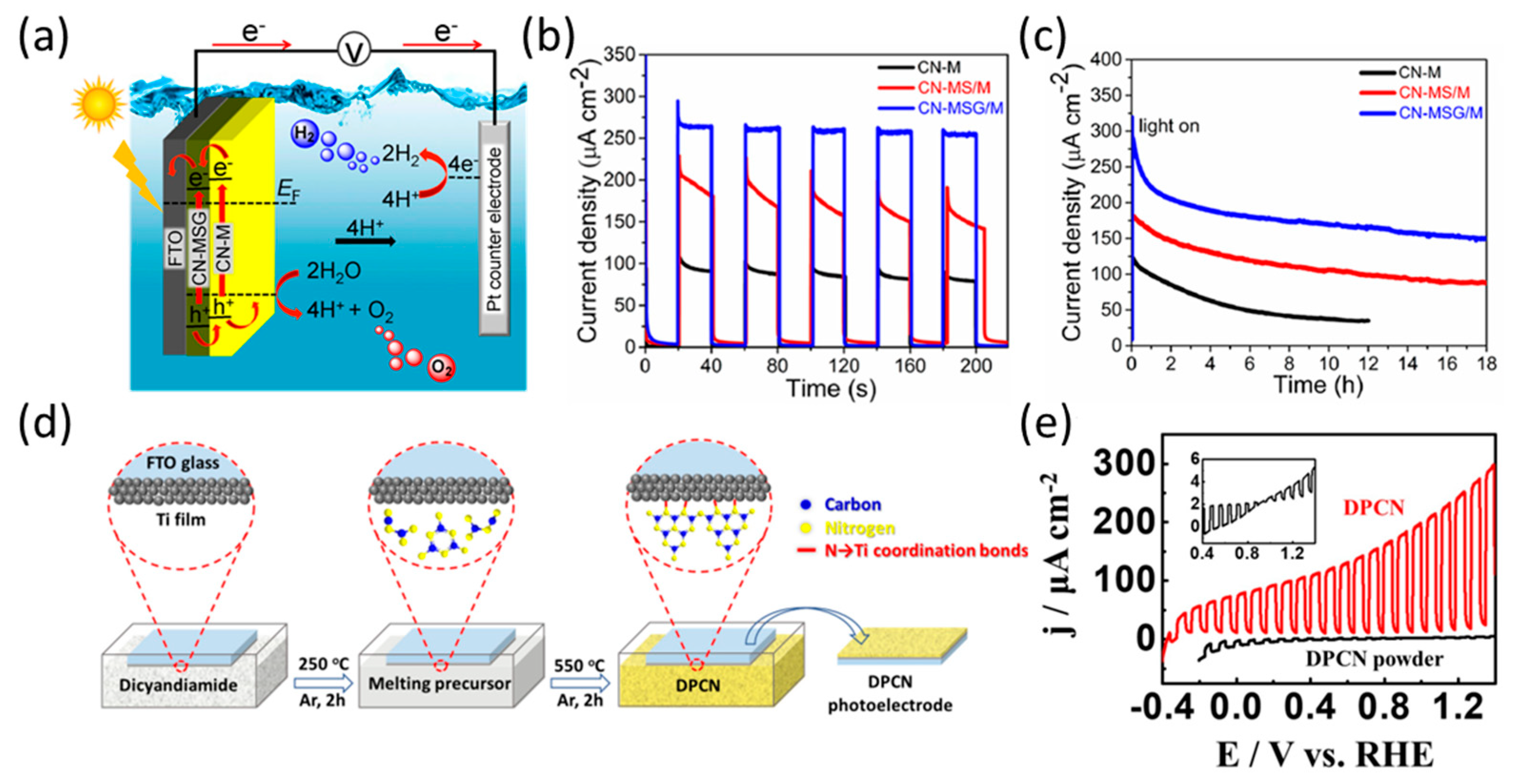
  60. Qin, J.; Barrio, J.; Peng, G.; Tzadikov, J.; Abisdris, L.; Volokh, M.; Shalom, M. Direct growth of uniform carbon nitride layers with extended optical absorption towards efficient water-splitting photoanodes. Nat. Commun. 2020, 11, 4701. [Google Scholar] [CrossRef]
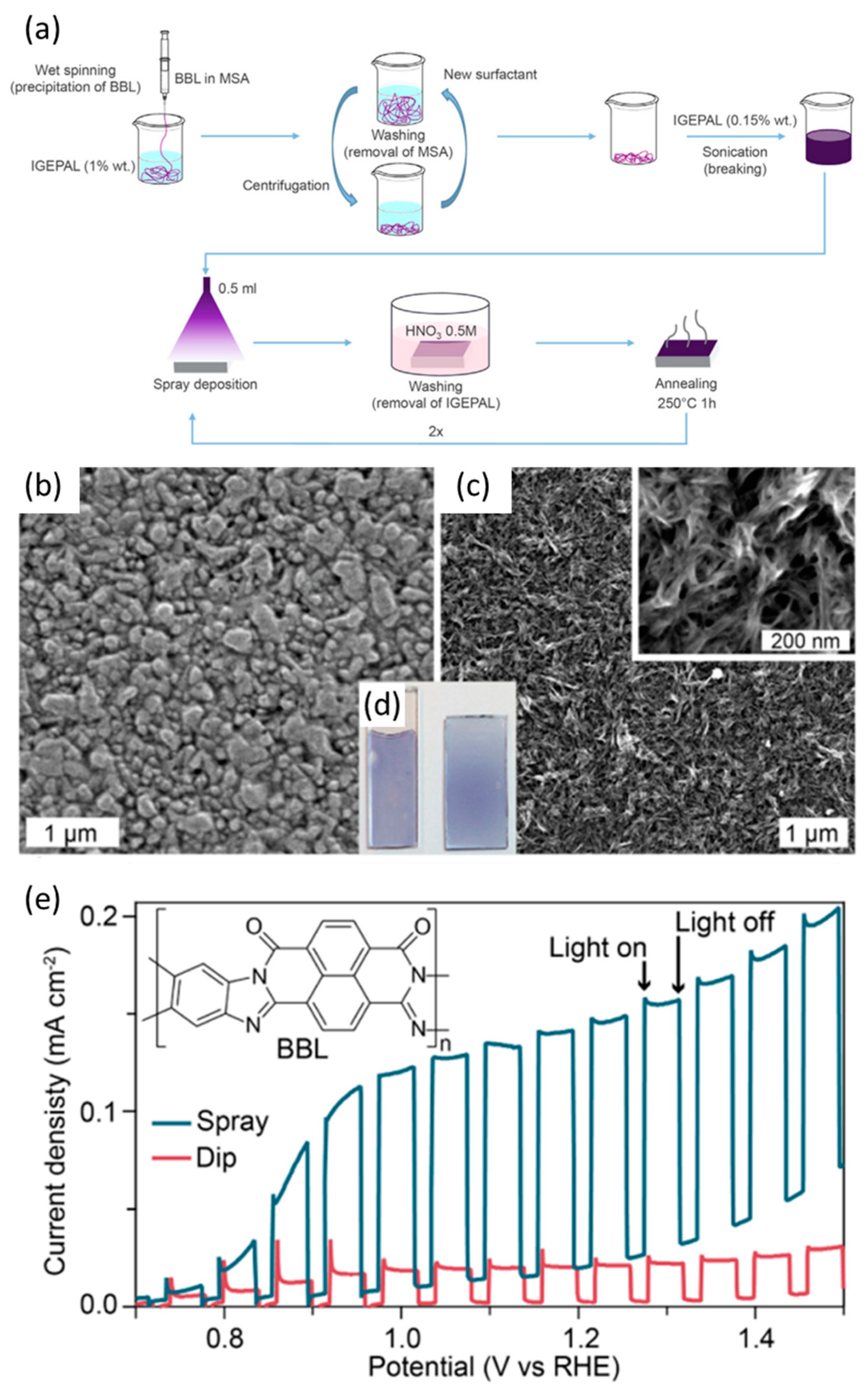
  61. Bornoz, P.; Prévot, M.S.; Yu, X.; Guijarro, N.; Sivula, K. Direct Light-Driven Water Oxidation by a Ladder-Type Conjugated Polymer Photoanode. J. Am. Chem. Soc. 2015, 137, 15338–15341. [Google Scholar] [CrossRef] [PubMed]
  62. Yoon, K.-Y.; Park, J.; Jung, M.; Ji, S.-G.; Lee, H.; Seo, J.H.; Kwak, M.-J.; Il Seok, S.; Lee, J.H.; Jang, J.-H. NiFeOx decorated Ge-hematite/perovskite for an efficient water splitting system. Nat. Commun. 2021, 12, 4309. [Google Scholar] [CrossRef] [PubMed]
  63. Reddy, D.A.; Kim, Y.; Shim, H.S.; Reddy, K.A.J.; Gopannagari, M.; Praveen Kumar, D.; Song, J.K.; Kim, T.K. Significant Improvements on BiVO4@CoPi Photoanode Solar Water Splitting Performance by Extending Visible-Light Harvesting Capacity and Charge Carrier Transportation. ACS Appl. Energy Mater. 2020, 3, 4474–4483. [Google Scholar] [CrossRef]
  64. Abe, T.; Nagai, K.; Kabutomori, S.; Kaneko, M.; Tajiri, A.; Norimatsu, T.J.A.C.I.E. An organic photoelectrode working in the water phase: Visible-light-induced dioxygen evolution by a perylene derivative/cobalt phthalocyanine bilayer. Angew. Chem. Int. Ed. 2006, 45, 2778–2781. [Google Scholar] [CrossRef]
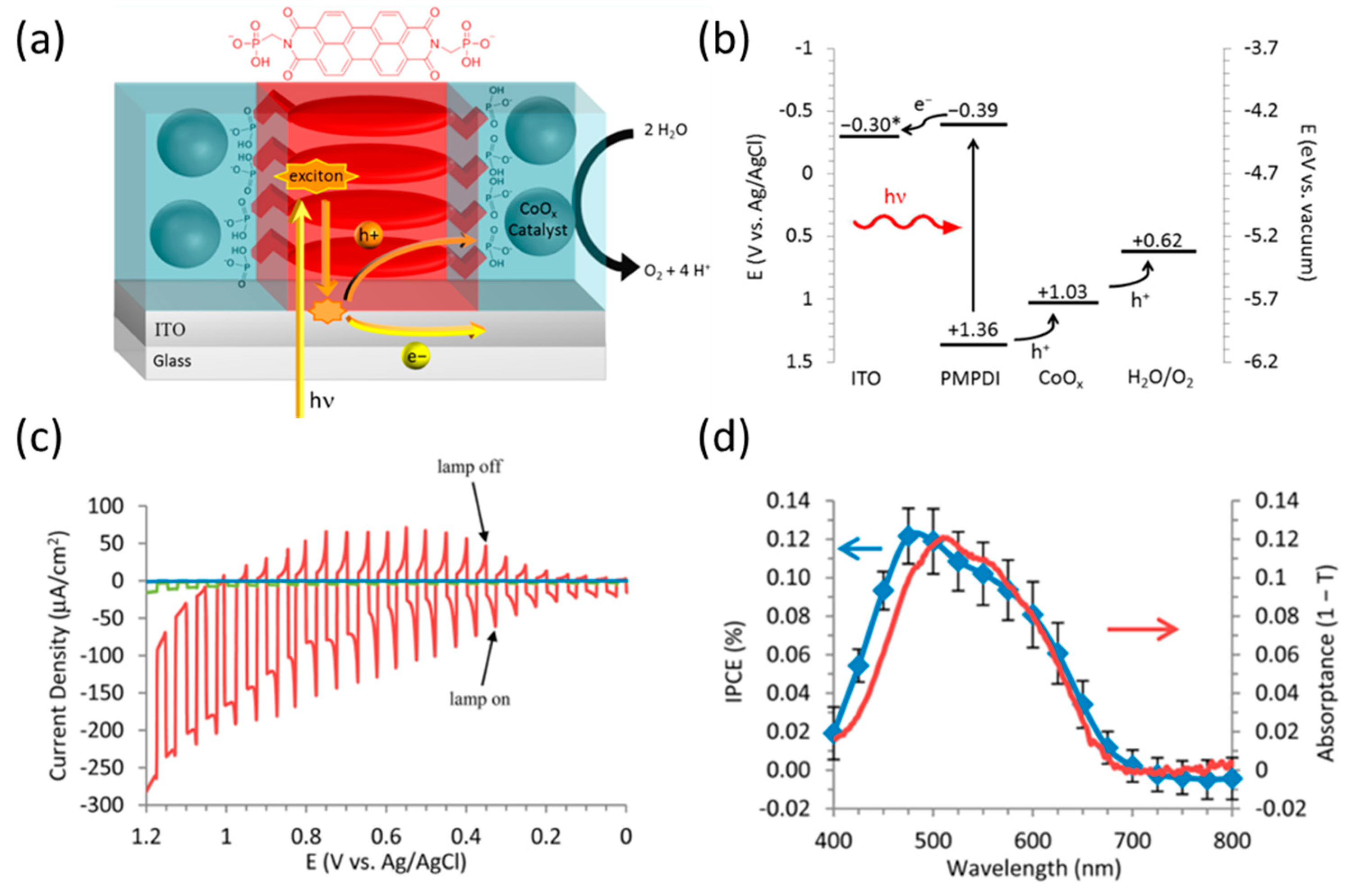
  65. Kirner, J.T.; Stracke, J.J.; Gregg, B.A.; Finke, R.G. Visible-Light-Assisted Photoelectrochemical Water Oxidation by Thin Films of a Phosphonate-Functionalized Perylene Diimide Plus CoOx Cocatalyst. ACS Appl. Mater. 2014, 6, 13367–13377. [Google Scholar] [CrossRef]
  66. Wang, L.; Yan, D.; Shaffer, D.W.; Ye, X.; Layne, B.H.; Concepcion, J.J.; Liu, M.; Nam, C.-Y. Improved Stability and Performance of Visible Photoelectrochemical Water Splitting on Solution-Processed Organic Semiconductor Thin Films by Ultrathin Metal Oxide Passivation. Chem. Mater. 2018, 30, 324–335. [Google Scholar] [CrossRef]
  67. Seo, Y.J.; Das, P.K.; Arunachalam, M.; Ahn, K.-S.; Ha, J.-S.; Kang, S.H. Drawing the distinguished graphite carbon nitride (g-C3N4) on SnO2 nanoflake film for solar water oxidation. Int. J. Hydrogen Energy 2020, 45, 22567–22575. [Google Scholar] [CrossRef]
  68. Karjule, N.; Barrio, J.; Xing, L.; Volokh, M.; Shalom, M. Highly Efficient Polymeric Carbon Nitride Photoanode with Excellent Electron Diffusion Length and Hole Extraction Properties. Nano Lett. 2020, 20, 4618–4624. [Google Scholar] [CrossRef]
  69. Fan, X.; Wang, Z.; Lin, T.; Du, D.; Xiao, M.; Chen, P.; Monny, S.A.; Huang, H.; Lyu, M.; Lu, M.; et al. Coordination Chemistry Engineered Polymeric Carbon Nitride Photoanode with Ultralow Onset Potential for Water Splitting. Angew. Chem. Int. Ed. 2022, 61, e202204407. [Google Scholar] [CrossRef]
  70. Li, G.; Zhu, R.; Yang, Y. Polymer solar cells. Nat. Photonics 2012, 6, 153–161. [Google Scholar] [CrossRef]
  71. Tang, C.W. Two-layer organic photovoltaic cell. Appl. Phys. Lett. 1986, 48, 183–185. [Google Scholar] [CrossRef]
  72. Athanasopoulos, S.; Hennebicq, E.; Beljonne, D.; Walker, A.B. Trap Limited Exciton Transport in Conjugated Polymers. J. Phys. Chem. C 2008, 112, 11532–11538. [Google Scholar] [CrossRef]
  73. Mikhnenko, O.V.; Kuik, M.; Lin, J.; van der Kaap, N.; Nguyen, T.-Q.; Blom, P.W.M. Trap-Limited Exciton Diffusion in Organic Semiconductors. Adv. Mater. 2014, 26, 1912–1917. [Google Scholar] [CrossRef]
  74. MacLeod, B.A.; Tremolet de Villers, B.J.; Schulz, P.; Ndione, P.F.; Kim, H.; Giordano, A.J.; Zhu, K.; Marder, S.R.; Graham, S.; Berry, J.J.; et al. Stability of inverted organic solar cells with ZnO contact layers deposited from precursor solutions. Energy Environ. Sci. 2015, 8, 592–601. [Google Scholar] [CrossRef]
  75. Irwin, M.D.; Buchholz, D.B.; Hains, A.W.; Chang, R.P.H.; Marks, T.J. p-Type semiconducting nickel oxide as an efficiency-enhancing anode interfacial layer in polymer bulk-heterojunction solar cells. Proc. Natl. Acad. Sci. USA 2008, 105, 2783–2787. [Google Scholar] [CrossRef]
  76. Gong, Y.; Dong, Y.; Zhao, B.; Yu, R.; Hu, S.; Tan, Z.a. Diverse applications of MoO3 for high performance organic photovoltaics: Fundamentals, processes and optimization strategies. J. Mater. Chem. A 2020, 8, 978–1009. [Google Scholar] [CrossRef]
  77. Kim, K.-D.; Lim, D.C.; Seo, H.O.; Lee, J.Y.; Seo, B.Y.; Lee, D.J.; Song, Y.; Cho, S.; Lim, J.-H.; Kim, Y.D. Enhanced performance of organic photovoltaics by TiO2-interlayer with precisely controlled thickness between ZnO electron collecting and active layers. Appl. Surf. Sci. 2013, 279, 380–383. [Google Scholar] [CrossRef]
  78. Peng, Y.; Yaacobi-Gross, N.; Perumal, A.K.; Faber, H.A.; Vourlias, G.; Patsalas, P.A.; Bradley, D.D.C.; He, Z.; Anthopoulos, T.D. Efficient organic solar cells using copper(I) iodide (CuI) hole transport layers. Appl. Phys. Lett. 2015, 106, 243302. [Google Scholar] [CrossRef]
  79. Park, Y.; Soon Choi, K.; Young Kim, S. Graphene oxide/PEDOT:PSS and reduced graphene oxide/PEDOT:PSS hole extraction layers in organic photovoltaic cells. Phys. Status Solidi A 2012, 209, 1363–1368. [Google Scholar] [CrossRef]
  80. Lee, B.; Jeong, S.; Cho, Y.; Jeong, M.; Lee, S.M.; Oh, J.; Yang, C. Highly Efficient Organic Photovoltaics Enhanced Using Organic Passivation Layer Vacuum Deposition. Adv. Funct. Mater. 2020, 30, 2005037. [Google Scholar] [CrossRef]
  81. Park, H.; Shi, Y.; Kong, J. Application of solvent modified PEDOT:PSS to graphene electrodes in organic solar cells. Nanoscale 2013, 5, 8934–8939. [Google Scholar] [CrossRef] [PubMed]
  82. Wadsworth, A.; Moser, M.; Marks, A.; Little, M.S.; Gasparini, N.; Brabec, C.J.; Baran, D.; McCulloch, I. Critical review of the molecular design progress in non-fullerene electron acceptors towards commercially viable organic solar cells. Chem. Soc. Rev. 2019, 48, 1596–1625. [Google Scholar] [CrossRef] [PubMed]
  83. Abe, T.; Nagai, K.; Sekimoto, K.; Tajiri, A.; Norimatsu, T. Novel characteristics at a fullerene/water interface in an organic bilayer photoelectrode of phthalocyanine/fullerene. Electrochem. Commun. 2005, 7, 1129–1132. [Google Scholar] [CrossRef]
  84. Abe, T.; Tobinai, S.; Nagai, K. Photocathode Kinetics of Phthalocyanine/Fullerene with Respect to the Base Electrode for the Bilayer Coating. Jpn. J. Appl. Phys. 2009, 48, 021503. [Google Scholar] [CrossRef]
  85. Ikezoi, K.; Chisaka, M.; Abe, T.J.I.J.E.S. Photocatalytic and photoelectrochemical production of hydrogen peroxide under acidic conditions in organic pn bilayer/bismuth vanadate system. Int. J. Electrochem. Sci. 2022, 17, 2. [Google Scholar]
  86. Sariciftci, N.S.; Smilowitz, L.; Heeger, A.J.; Wudl, F. Photoinduced Electron Transfer from a Conducting Polymer to Buckminsterfullerene. Science 1992, 258, 1474–1476. [Google Scholar] [CrossRef]
  87. Liu, T.; Troisi, A. What Makes Fullerene Acceptors Special as Electron Acceptors in Organic Solar Cells and How to Replace Them. Adv. Mater. 2013, 25, 1038–1041. [Google Scholar] [CrossRef]
  88. Lanzarini, E.; Antognazza, M.R.; Biso, M.; Ansaldo, A.; Laudato, L.; Bruno, P.; Metrangolo, P.; Resnati, G.; Ricci, D.; Lanzani, G. Polymer-Based Photocatalytic Hydrogen Generation. J. Phys. Chem. C 2012, 116, 10944–10949. [Google Scholar] [CrossRef]
  89. Chen, L.-M.; Hong, Z.; Li, G.; Yang, Y. Recent Progress in Polymer Solar Cells: Manipulation of Polymer:Fullerene Morphology and the Formation of Efficient Inverted Polymer Solar Cells. Adv. Mater. 2009, 21, 1434–1449. [Google Scholar] [CrossRef]
  90. Ma, W.; Yang, C.; Gong, X.; Lee, K.; Heeger, A.J. Thermally Stable, Efficient Polymer Solar Cells with Nanoscale Control of the Interpenetrating Network Morphology. Adv. Funct. Mater. 2005, 15, 1617–1622. [Google Scholar] [CrossRef]
  91. Shao, D.; Cheng, Y.; He, J.; Feng, D.; Zheng, L.; Zheng, L.; Zhang, X.; Xu, J.; Wang, W.; Wang, W.; et al. A Spatially Separated Organic–Inorganic Hybrid Photoelectrochemical Cell for Unassisted Overall Water Splitting. ACS Catal. 2017, 7, 5308–5315. [Google Scholar] [CrossRef]
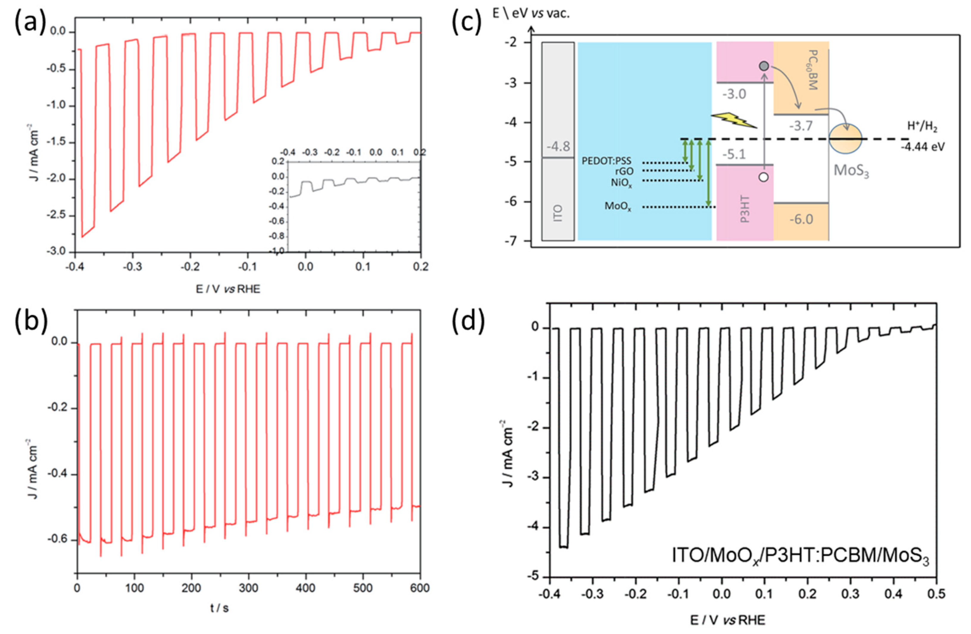
  92. Bourgeteau, T.; Tondelier, D.; Geffroy, B.; Brisse, R.; Laberty-Robert, C.; Campidelli, S.; de Bettignies, R.; Artero, V.; Palacin, S.; Jousselme, B. A H2-evolving photocathode based on direct sensitization of MoS3 with an organic photovoltaic cell. Energy Environ. Sci. 2013, 6, 2706–2713. [Google Scholar] [CrossRef]
  93. Bourgeteau, T.; Tondelier, D.; Geffroy, B.; Brisse, R.; Campidelli, S.; Cornut, R.; Jousselme, B. All solution-processed organic photocathodes with increased efficiency and stability via the tuning of the hole-extracting layer. J. Mater. Chem. A 2016, 4, 4831–4839. [Google Scholar] [CrossRef]
  94. Haro, M.; Solis, C.; Molina, G.; Otero, L.; Bisquert, J.; Gimenez, S.; Guerrero, A. Toward Stable Solar Hydrogen Generation Using Organic Photoelectrochemical Cells. J. Phys. Chem. C 2015, 119, 6488–6494. [Google Scholar] [CrossRef]
  95. Belarb, E.; Blas-Ferrando, V.M.; Haro, M.; Maghraoui-Meherzi, H.; Gimenez, S. Electropolymerized polyaniline: A promising hole selective contact in organic photoelectrochemical cells. Chem. Eng. Sci. 2016, 154, 143–149. [Google Scholar] [CrossRef]
  96. Bellani, S.; Najafi, L.; Martín-García, B.; Ansaldo, A.; Del Rio Castillo, A.E.; Prato, M.; Moreels, I.; Bonaccorso, F. Graphene-Based Hole-Selective Layers for High-Efficiency, Solution-Processed, Large-Area, Flexible, Hydrogen-Evolving Organic Photocathodes. J. Phys. Chem. C 2017, 121, 21887–21903. [Google Scholar] [CrossRef]
  97. Fumagalli, F.; Bellani, S.; Schreier, M.; Leonardi, S.; Rojas, H.C.; Ghadirzadeh, A.; Tullii, G.; Savoini, A.; Marra, G.; Meda, L.; et al. Hybrid organic–inorganic H2-evolving photocathodes: Understanding the route towards high performance organic photoelectrochemical water splitting. J. Mater. Chem. A 2016, 4, 2178–2187. [Google Scholar] [CrossRef]
  98. Mezzetti, A.; Fumagalli, F.; Alfano, A.; Iadicicco, D.; Antognazza, M.R.; di Fonzo, F. Stable hybrid organic/inorganic photocathodes for hydrogen evolution with amorphous WO3 hole selective contacts. Faraday Discuss. 2017, 198, 433–448. [Google Scholar] [CrossRef]
  99. Bellani, S.; Najafi, L.; Capasso, A.; Del Rio Castillo, A.E.; Antognazza, M.R.; Bonaccorso, F. Few-layer MoS2 flakes as a hole-selective layer for solution-processed hybrid organic hydrogen-evolving photocathodes. J. Mater. Chem. A 2017, 5, 4384–4396. [Google Scholar] [CrossRef]
  100. Rojas, H.C.; Bellani, S.; Fumagalli, F.; Tullii, G.; Leonardi, S.; Mayer, M.T.; Schreier, M.; Grätzel, M.; Lanzani, G.; Di Fonzo, F.; et al. Polymer-based photocathodes with a solution-processable cuprous iodide anode layer and a polyethyleneimine protective coating. Energy Environ. Sci. 2016, 9, 3710–3723. [Google Scholar] [CrossRef]
  101. Haro, M.; Solis, C.; Blas-Ferrando, V.M.; Margeat, O.; Dhkil, S.B.; Videlot-Ackermann, C.; Ackermann, J.; Di Fonzo, F.; Guerrero, A.; Gimenez, S. Direct Hydrogen Evolution from Saline Water Reduction at Neutral pH using Organic Photocathodes. ChemSusChem 2016, 9, 3062–3066. [Google Scholar] [CrossRef] [PubMed]
  102. Steier, L.; Bellani, S.; Rojas, H.C.; Pan, L.; Laitinen, M.; Sajavaara, T.; Di Fonzo, F.; Grätzel, M.; Antognazza, M.R.; Mayer, M.T. Stabilizing organic photocathodes by low-temperature atomic layer deposition of TiO2. Sustain. Energy Fuels 2017, 1, 1915–1920. [Google Scholar] [CrossRef]
  103. Rojas, H.C.; Bellani, S.; Sarduy, E.A.; Fumagalli, F.; Mayer, M.T.; Schreier, M.; Grätzel, M.; Di Fonzo, F.; Antognazza, M.R. All Solution-Processed, Hybrid Organic–Inorganic Photocathode for Hydrogen Evolution. ACS Omega 2017, 2, 3424–3431. [Google Scholar] [CrossRef] [PubMed]
  104. Ghadirzadeh, A.; Fumagalli, F.; Mezzetti, A.; Bellani, S.; Meda, L.; Antognazza, M.R.; Di Fonzo, F. A Three-Dimensional Architecture for Hydrogen-Evolving, Host/Guest, Hybrid Organic/Inorganic Photocathodes Based on Nanolamellar MoO3 Scaffolds. ChemPhotoChem 2018, 2, 283–292. [Google Scholar] [CrossRef]
  105. Bourgeteau, T.; Tondelier, D.; Geffroy, B.; Brisse, R.; Cornut, R.; Artero, V.; Jousselme, B. Enhancing the Performances of P3HT:PCBM–MoS3-Based H2-Evolving Photocathodes with Interfacial Layers. ACS Appl. Mater. 2015, 7, 16395–16403. [Google Scholar] [CrossRef]
  106. Morozan, A.; Bourgeteau, T.; Tondelier, D.; Geffroy, B.; Jousselme, B.; Artero, V. Noble metal-free hydrogen-evolving photocathodes based on small molecule organic semiconductors. Nanotechnology 2016, 27, 355401. [Google Scholar] [CrossRef]
  107. Liu, Q.; Toudert, J.; Liu, F.; Mantilla-Perez, P.; Bajo, M.M.; Russell, T.P.; Martorell, J. Circumventing UV Light Induced Nanomorphology Disorder to Achieve Long Lifetime PTB7-Th:PCBM Based Solar Cells. Adv. Energy Mater. 2017, 7, 1701201. [Google Scholar] [CrossRef]
  108. Guo, Y.; Li, Y.; Awartani, O.; Zhao, J.; Han, H.; Ade, H.; Zhao, D.; Yan, H. A Vinylene-Bridged Perylenediimide-Based Polymeric Acceptor Enabling Efficient All-Polymer Solar Cells Processed under Ambient Conditions. Adv. Mater. 2016, 28, 8483–8489. [Google Scholar] [CrossRef]
  109. Yao, L.; Guijarro, N.; Boudoire, F.; Liu, Y.; Rahmanudin, A.; Wells, R.A.; Sekar, A.; Cho, H.-H.; Yum, J.-H.; Le Formal, F.; et al. Establishing Stability in Organic Semiconductor Photocathodes for Solar Hydrogen Production. J. Am. Chem. Soc. 2020, 142, 7795–7802. [Google Scholar] [CrossRef]
  110. Wu, Y.; Liu, D.; Zhuang, H.; Le, J.; Kuang, Y. High-performance bulk heterojunction-based photocathode with facile architecture for photoelectrochemical water splitting. Chin. Chem. Lett. 2023, 34, 107480. [Google Scholar] [CrossRef]
  111. Seo, S.; Lee, J.-H.; Kim, Y.; Kim, S.; Yoon, C.J.; Choi, H.; Lee, S.; Lee, K.; Kim, H.; Lee, S. A long-term stable organic semiconductor photocathode-based photoelectrochemical module system for hydrogen production. J. Mater. Chem. A 2022, 10, 13247–13253. [Google Scholar] [CrossRef]
  112. Cha, H.; Wu, J.; Wadsworth, A.; Nagitta, J.; Limbu, S.; Pont, S.; Li, Z.; Searle, J.; Wyatt, M.F.; Baran, D.; et al. An Efficient, “Burn in” Free Organic Solar Cell Employing a Nonfullerene Electron Acceptor. Adv. Mater. 2017, 29, 1701156. [Google Scholar] [CrossRef]
  113. Liu, G.; Chen, C.; Ji, H.; Ma, W.; Zhao, J. Photo-electrochemical water splitting system with three-layer n-type organic semiconductor film as photoanode under visible irradiation. Sci. China Chem. 2012, 55, 1953–1958. [Google Scholar] [CrossRef]
  114. Cho, H.-H.; Yao, L.; Yum, J.-H.; Liu, Y.; Boudoire, F.; Wells, R.A.; Guijarro, N.; Sekar, A.; Sivula, K. A semiconducting polymer bulk heterojunction photoanode for solar water oxidation. Nat. Catal. 2021, 4, 431–438. [Google Scholar] [CrossRef]
  115. Kang, T.E.; Cho, H.-H.; Kim, H.j.; Lee, W.; Kang, H.; Kim, B.J. Importance of Optimal Composition in Random Terpolymer-Based Polymer Solar Cells. Macromolecules 2013, 46, 6806–6813. [Google Scholar] [CrossRef]
  116. Cho, H.-H.; Kim, S.; Kim, T.; Sree, V.G.; Jin, S.-H.; Kim, F.S.; Kim, B.J. Design of Cyanovinylene-Containing Polymer Acceptors with Large Dipole Moment Change for Efficient Charge Generation in High-Performance All-Polymer Solar Cells. Adv. Energy Mater. 2018, 8, 1701436. [Google Scholar] [CrossRef]
  117. Gao, J.; Xu, C.-Q.; Hung, S.-F.; Liu, W.; Cai, W.; Zeng, Z.; Jia, C.; Chen, H.M.; Xiao, H.; Li, J.; et al. Breaking Long-Range Order in Iridium Oxide by Alkali Ion for Efficient Water Oxidation. J. Am. Chem. Soc. 2019, 141, 3014–3023. [Google Scholar] [CrossRef]
  118. Sekar, A.; Moreno-Naranjo, J.M.; Liu, Y.; Yum, J.-H.; Darwich, B.P.; Cho, H.-H.; Guijarro, N.; Yao, L.; Sivula, K. Bulk Heterojunction Organic Semiconductor Photoanodes: Tuning Energy Levels to Optimize Electron Injection. ACS Appl. Mater. 2022, 14, 8191–8198. [Google Scholar] [CrossRef]
  119. Zhang, R.; Sun, X.; Zheng, L.; Diao, L.; Chen, F.; Li, Y.; Wang, S.; Wang, Y.; Wang, W.; Lu, F.; et al. Organic Photocathode Supported by Copper Nanosheets Array for Overall Water Splitting. Chem. Eur. J. 2022, 28, e202103495. [Google Scholar] [CrossRef]
  120. Wang, B.; Fu, Y.; Yan, C.; Zhang, R.; Yang, Q.; Han, Y.; Xie, Z. Insight into the Role of PC71BM on Enhancing the Photovoltaic Performance of Ternary Organic Solar Cells. Front. Chem. 2018, 6, 198. [Google Scholar] [CrossRef]
  121. Ye, S.; Shi, W.; Liu, Y.; Li, D.; Yin, H.; Chi, H.; Luo, Y.; Ta, N.; Fan, F.; Wang, X.; et al. Unassisted Photoelectrochemical Cell with Multimediator Modulation for Solar Water Splitting Exceeding 4% Solar-to-Hydrogen Efficiency. J. Am. Chem. Soc. 2021, 143, 12499–12508. [Google Scholar] [CrossRef] [PubMed]
  122. Alfano, A.; Mezzetti, A.; Fumagalli, F.; Tao, C.; Rovera, E.; Petrozza, A.; Di Fonzo, F. Photoelectrochemical water splitting by hybrid organic-inorganic systems: Setting the path from 2% to 20% solar-to-hydrogen conversion efficiency. iScience 2021, 24, 102463. [Google Scholar] [CrossRef] [PubMed]
  123. Zhang, Y.; Lv, H.; Zhang, Z.; Wang, L.; Wu, X.; Xu, H. Stable Unbiased Photo-Electrochemical Overall Water Splitting Exceeding 3% Efficiency via Covalent Triazine Framework/Metal Oxide Hybrid Photoelectrodes. Adv. Mater. 2021, 33, 2008264. [Google Scholar] [CrossRef] [PubMed]
  124. Yao, L.; Liu, Y.; Cho, H.-H.; Xia, M.; Sekar, A.; Primera Darwich, B.; Wells, R.A.; Yum, J.-H.; Ren, D.; Grätzel, M.; et al. A hybrid bulk-heterojunction photoanode for direct solar-to-chemical conversion. Energy Environ. Sci. 2021, 14, 3141–3151. [Google Scholar] [CrossRef]
  125. Zhang, D.; Cho, H.-H.; Yum, J.-H.; Mensi, M.; Sivula, K. An Organic Semiconductor Photoelectrochemical Tandem Cell for Solar Water Splitting. Adv. Energy Mater. 2022, 12, 2202363. [Google Scholar] [CrossRef]
  126. Mase, K.; Yoneda, M.; Yamada, Y.; Fukuzumi, S. Seawater usable for production and consumption of hydrogen peroxide as a solar fuel. Nat. Commun. 2016, 7, 11470. [Google Scholar] [CrossRef]
  127. Ko, M.; Pham, L.T.M.; Sa, Y.J.; Woo, J.; Nguyen, T.V.T.; Kim, J.H.; Oh, D.; Sharma, P.; Ryu, J.; Shin, T.J.; et al. Unassisted solar lignin valorisation using a compartmented photo-electro-biochemical cell. Nat. Commun. 2019, 10, 5123. [Google Scholar] [CrossRef]
  128. Mehrotra, R.; Oh, D.; Jang, J.-W. Unassisted selective solar hydrogen peroxide production by an oxidised buckypaper-integrated perovskite photocathode. Nat. Commun. 2021, 12, 6644. [Google Scholar] [CrossRef]
  129. Song, J.; Yu, J.M.; Ahn, J.H.; Cho, H.; Oh, J.; Kim, Y.S.; Kim, J.; Ko, M.; Lee, S.-H.; Shin, T.J.; et al. Selective, Stable, Bias-Free, and Efficient Solar Hydrogen Peroxide Production on Inorganic Layered Materials. Adv. Funct. Mater. 2022, 32, 2110412. [Google Scholar] [CrossRef]
Figure 1. (a) Illustration of the employed poly(1,3,5-triethynylbenzene) (PTEB) nanofibers and structure of molecules on substrate. (b) Current density-potential curves of the PTEB photocathode. (c) Comparison of the UV-Vis absorption spectra of PTEB, PDET, and PTEB1.3-co-PDET1. Inset image shows the molecular structure of PTEB1.3-co-PDET1. (d) Band diagram of the PTEB1.3-co-PDET1 compared with PTEB. (e) Transient photocurrent density vs. time of PTEB and PTEB1.3-co-PDET1 photocathode at 0 V vs. RHE [52]. Copyright 2018, Nature Publishing Group.
Catalysts 13 00814 g001
Figure 2. (a) Molecular structures of COFs for PEC H2 evolution. (b) LUMO/HOMO positions. (c) Linear sweep voltammetry (LSV) curves of TTA-TTB and TAPB-TTB COF [54]. Copyright 2021, Wiley.
Catalysts 13 00814 g002
Figure 3. (a) Illustration of the melamine film fabrication. (b) LSV curves in 1 M KOH, (c) 0.1 M NaH2PO4 (pH 7), and 0.5 M H2SO4 electrolytes of CN film [59]. Copyright 2018, Wiley. (d) Synthetic process of CNT film. (e) LSV curves of CNT electrode in 0.1 M KOH with and without light. (f) Photocurrent density vs. time curves of CNT electrodes at 1.23 V vs. RHE in 0.1 M KOH and in 0.1 M KOH containing 10% (v/v) TEOA [60]. Copyright 2020, Nature Publishing Group.
Catalysts 13 00814 g003
Figure 4. (a) Illustration of the dip-coating method used to fabricate the poly[benzimidazobenzophenanthroline] (BBL) photoanode. (b) Scanning electron microscope (SEM) top-view image of optimized dip-coated and (c) Sprayed films, with (d) Corresponding optical images of the BBL films. (e) LSV curves of a sprayed-coated film and a dip-coated film in a sacrificial electrolyte (0.5 M Na2SO3, pH 7) under chopped light illumination [61]. Copyright 2015, American Chemical Society.
Catalysts 13 00814 g004
Figure 5. (a) Schematic of the N,N′-bis(phosphonomethyl)-3,4,9,10-perylenediimide (PMPDI) photocathode structure and the role of each compound. (b) Band diagram for the ITO/PMPDI/CoOx system. * The actual potential of ITO in most experiments in this study is that applied via potentiostat vs. Ag/AgCl. (c) Photocurrent transients vs. applied potential for ITO/PMPDI/CoOx (red), ITO/PMPDI (green). (d) Comparison of the average photon-to-current conversion efficiency (IPCE) and standard deviation (blue) using a two-electrode configuration and the absorptance spectrum (red) of a dry PMPDI film [65]. Copyright 2014, American Chemical Society.
Catalysts 13 00814 g005
Figure 6. (a) Schematic energy band diagram depicting the band alignment between the [6,6]-phenyl-C71-butyric acid methyl ester (PC71BM) thin film and ZnO passivation layer. Inset image shows the molecular structure of PC71BM. (b) Average photocurrent density measured during the first PEC scan cycle with respect to the ZnO passivation thickness at 1.95 V vs. RHE (top) and 1.23 V vs. RHE (bottom). (c) LSV curves of PC71BM photoanodes with 1.26 nm of ZnO passivation (orange) and without passivation layer (blue). (d) Durability measurements of PC71BM photoanodes with 1.44 nm ZnO passivation (red) and without passivation layer (blue) [66]. Copyright 2018, American Chemical Society.
Catalysts 13 00814 g006
Figure 7. (a) Illustration of the band diagram of the overall PEC system featuring a CN-based photocathode. (b) Photocurrent density of CN electrodes at 1.23 V vs. RHE in 0.1 M KOH. (c) Photocurrent density of CN electrodes at 1.23 V vs. RHE in a 0.1 M KOH electrolyte during 18 h of continuous 1 sun illumination [68]. Copyright 2020, American Chemical Society. (d) Schematic illustration of the procedure for Ti-induced growth of polymeric CN film. (e) LSV curves of the DPCN and the DPCN powder photoelectrodes in a 0.5 M H2SO4 electrolyte [69]. Copyright 2022, Wiley.
Catalysts 13 00814 g007
Figure 8. (a) LSV curves with chopped visible light for an ITO/P3HT:PCBM/MoS3 photocathode in 0.5 M H2SO4. (b) Chronoamperometry (CA) curve at 0 V vs. RHE in 0.5 M H2SO4 with chopped visible light for the same ITO/P3HT:PCBM/MoS3 photocathode. (c) Energy band diagram of an ITO/HTL/P3HT:PCBM/MoS3 photocathode for HER with different HTLs (PEDOT:PSS, rGO, NiOx, and MoOx). (d) LSV curves of P3HT:PCBM photocathode with MoOx as a HTLs [93]. Copyright 2016, Royal Society of Chemistry.
Catalysts 13 00814 g008
Figure 9. (a) Device architecture of the optimized organic PEC cell and energy diagram of the device, along with literature values measured under vacuum conditions. Inset images show the molecular structure of P3HT and PEDOT:PSS. (b) LSV curves of ITO/x-PEDOT/BHJ, ITO/x-PEDOT/BHJ/Pt, ITO/Pt, ITO/x-PEDOT/BHJ/TiOx/Pt (50 nm), and ITO/x-PEDOT/BHJ/TiOx/Pt (140 nm) in 0.1 M Na2SO4 (pH 2) under chopped illumination. (c,d) Normalized CA measurements for the glass/ITO/x-PEDOT:PSS/P3HT:PCBM/TiOx/Pt configuration. (c) Highest photocurrent devices with a thin layer of TiOx/Pt (40 nm) measured at 0.15 V vs. RHE. (d) Most stable photocathode with a thick layer of TiOx/Pt (150 nm) measured at 0 V vs. RHE [94]. Copyright 2015, American Chemical Society.
Catalysts 13 00814 g009
Figure 10. (a) Cross-sectional SEM image of the hybrid organic/inorganic photocathode. (b) Energy band diagram illustrating the materials assembled in the hybrid photocathode. (c) Comparison of hybrid photocathodes of the full device (blue) and the device lacking the TiO2 layer (green). (d) High-resolution SEM image showing Pt delamination and folded fragments. (e) LSV scan under chopped light of a photocathode protected with an overlayer of polyethyleneimine (PEI) 0.1% (pink) compared to the device without the overlayer (blue). (f) H2 detection during CA measurement from a hybrid photocathode protected with an overlayer of PEI 0.1% [100]. Copyright 2016, Royal Society of Chemistry.
Catalysts 13 00814 g010
Figure 11. (a) Chemical structures of PTB7-Th and PDI-V, as well as the energy levels of each layer in a bulk heterojunction (BHJ) organic photocathode with a schematic image. (b) Schematic image of RuO2 deposited bulk heterojunction (BHJ) organic photocathode. (c) LSV curves of the FTO/MoO3/PTB7-Th:PDI-V/RuO2 photocathode under 1 sun illumination in an acidic electrolyte (pH 1). (d) Continuous illumination durability measurement of the FTO/MoO3/PTB7-Th:PDI-V/RuO2 photocathode at 0 V vs. RHE in a pH 1 electrolyte [109]. Copyright 2020, American Chemical Society.
Catalysts 13 00814 g011
Figure 12. (a) Schematic representation of each layer and device architecture and molecular structure of EH-IDTBR. (b) LSV curves of organic photocathodes in 0.5 M H2SO4. (c) CA measurements at 0 V vs. RHE. (d) CA measurements of the optimized Pt/Ti/Ag/OS photocathode for 30 h at 0 V vs. RHE. (e) Repetitive LSV curves of the Pt/Ti/Ag/OS photocathode for 10 cycles [111]. Copyright 2022, Royal Society of Chemistry.
Catalysts 13 00814 g012
Figure 13. (a) Molecular structures of PM6 and Y6. (b) Schematic of the device architecture. (c) Energy levels of the Y6:PM6/PM6 photoanode. (d) LSV curves of the Y6:PM6/PM6 and the Y6:PM6 photoanode in a 0.1 M KOH electrolyte under 1 sun illumination. (e) Normalized CA curves at 1.23 V vs. RHE. The inset shows the oxygen evolution on the surface of the Y6:PM6/PM6 photoanode. (f) Negative charge as a function of the applied bias, obtained by integration of the negative transient current [42]. Copyright 2022, Wiley.
Catalysts 13 00814 g013
Figure 14. (a) LSV curve of PBDB-T:ITIC-based OPVs under AM 1.5 G illumination. (b) Schematic image of the device architecture. (c) LSV curves of optimized LDH/Ni/eu@nfOP and Ni/eu@nfOP in a 1 M NaOH electrolyte. (d) Half solar-to-hydrogen conversion efficiency (Half-STH) value of LDH/Nieu@nfOP measured in a two-electrode system. (e) Comparison of CA measurements of LDH/Ni/eu@nfOP, Ni/eu@nfOP, and nfOP. (f) Comparison of normalized CA curves of LDH/Ni/eu@nfOP under AM 1.5 G illumination and visible light. (g) Overall schematic of the PBDB-T:ITIC-based organic photoanode configuration. (h) Previously reported half-STH value and photocurrent density at 1.23 V vs. RHE of photoanodes [43]. Copyright 2020, Nature Publishing Group.
Catalysts 13 00814 g014
Figure 15. (a) LSV curves of different ternary BHJ photocathodes based on PBDB-T:ITIC:PC71BM (PIP) in a 0.1 M H2SO4 electrolyte (pH 1). (b) UV-Vis spectra of BiVO4 and PIP as light-harvesting semiconductors. (c) Schematic representation of a PEC cell with a Co4O4/pGO/BiVO4/SnOx photoanode (front) wired to the Pt/TiOx/PIP/CuOx photocathode (behind). (d) LSV curves of a two-electrode configuration in 0.2 M potassium phosphate buffer (pH 7) [121]. Copyright 2021, American Chemical Society. (e) Schematic image of a PV-PEC tandem configuration and energy band diagram and interconnections of the system elements. (f) LSV curves of the three tandem systems under current matching, showing the expected working performance and STH efficiency (top), and the actual performance and STH value of the tandem stack during operation [122]. Copyright 2021, CellPress.
Catalysts 13 00814 g015
Figure 16. (a) LSV curve of CPN:SnO2 photoanode in 1 M iodide electrolyte (pH 1) with varying SnO2 nanoparticle thickness. (b) Schematic of the side-by-side configuration for unassisted solar HI splitting with an all-organic semiconductor-based PEC cell with different layers of the photocathode and photoanode. (c) Two-electrode current measurement without applied bias obtained in a 1 M HI electrolyte [124]. Copyright 2021, Royal Society of Chemistry. (d) Schematic representation of a tandem cell with an FTO/SAM/BHJ-1/RuO2 photocathode for water reduction and an FTO/mZnO/BHJ-3/PTAA/Li-IrO2 photoanode for water oxidation. (e) LSV curves of the FTO/SAM/BHJ-1/RuO2 photocathode and FTO/mZnO/BHJ-3/PTAA/Li-IrO2 photoanode (behind photocathode). (f) Photocurrent and solar-to-hydrogen (STH) efficiency of the tandem cell in a 0.1 M NaBi buffer (pH 9). [125]. Copyright 2022, Wiley.
Catalysts 13 00814 g016
Figure 17. (a) Schematic representation of the two-compartment PEC H2O2 production system with Co-containing MgAl layered double hydroxide (LDH) and BHJ organic photoanode. (b) Schematic image of 2m-LDH/Ni/eu@nfOP. (c) LSV curves of the 2m-LDH/Ni/eu@nfOP, LDH/Ni/eu@nfOP, and rutile TiO2 photoanode in a 0.1 M KOH electrolyte. (d) Concentration of H2O2 generated per unit area of each photoanode in the bias-free PEC system. (e) Solar-to-chemical conversion efficiencies (SCC, bar) and conversion rates (dots) of (10−3 Co) MgAl LDH with 2m-LDH/Ni/eu@nfOP (pink) and rutile TiO2 (green) [129]. Copyright 2022, Wiley.
Catalysts 13 00814 g017
Disclaimer/Publisher’s Note: The statements, opinions and data contained in all publications are solely those of the individual author(s) and contributor(s) and not of MDPI and/or the editor(s). MDPI and/or the editor(s) disclaim responsibility for any injury to people or property resulting from any ideas, methods, instructions or products referred to in the content.

