Article

Exploring Simultaneous Upgrading and Purification of Biomass−Gasified Gases Using Plasma Catalysis

1
Key Laboratory of Renewable Energy, CAS, Guangdong Provincial Key Laboratory of New and Renewable Energy Research and Development, Guangzhou Institute of Energy Conversion, Chinese Academy of Sciences, Guangzhou 510640, China
2
University of Chinese Academy of Sciences, Beijing 100049, China
3
School of Energy Science and Engineering, Central South University, Changsha 410083, China
*
Author to whom correspondence should be addressed.
Catalysts 2023, 13(4), 686; https://doi.org/10.3390/catal13040686
Submission received: 7 March 2023 / Revised: 28 March 2023 / Accepted: 30 March 2023 / Published: 31 March 2023
(This article belongs to the Section Biomass Catalysis)

Abstract

:
Tar and substantial CH4 and CO2 are contained in gasified fuels, which pose an obstacle to direct chemical synthesis, and this is a predominant challenge for biomass gasification technology. Herein, a packed−bed dielectric barrier discharge (DBD) reactor was built for simultaneous CH4 dry reforming and tar removal with a La−Ni/γ−Al2O3 catalyst. The interaction between CH4 dry reforming and tar removal in plasma catalysis was investigated. The results indicated that plasma catalysis can achieve high−efficiency simultaneous tar removal and CH4 dry reforming, as indicated by the reactants’ conversion (14% increase for CCH4 and CCO2 at 450 °C in the presence of tar and a 37% increase for the tar removal rate at 360 °C when CH4 and CO2 were introduced), and the mechanism for mutual promotion of CH4 dry reforming and tar removal was elucidated through catalyst characterization results. In addition, a possible reaction mechanism for tar removal via plasma catalysis was proposed. These findings provide valuable insights for simultaneous upgrading and purification of gases generated by biomass gasification.

1. Introduction

The continuously−increasing depletion of fossil fuels and the growing threat of global warming are driving the development of carbon−neutral biomass energy utilization technology [1,2,3]. Gasification, which involves partial oxidation of the carbon contained in biomass by controlling the oxidant amount and gasifying agent, is considered a promising and sustainable thermochemical conversion procedure for biomass utilization. Gasification enables high−efficiency conversion of biomass into valuable syngas, mainly containing H2, CO and CH4, and it provides great flexibility for the generation of heat and electricity or syntheses of chemical products and value−added byproducts [4,5]. However, gasification syngas inevitably contains non−directly utilized gases, such as CH4 and CO2, both of which contribute significantly to global warming [6]. In addition, the presence of tars produced from the gasification process is also a major challenge for most syngas applications. The tars in the producer gas cause scaling, blocking and corrosion of downstream equipment, limiting the use of syngas for industrial applications [7,8]. Thus, simultaneous effective CH4–CO2 conversion/reforming and tar removal from raw fuel gas are of great importance for the gasification process.
CH4–CO2 reforming, described as dry reforming of methane (DRM) (Equation (1)), is an effective channel for the utilization of greenhouse gases (GHGs) as carbon sources [9,10]. In addition, DRM has been recommended as a promising way to generate valuable syngas with a H2/CO molar ratio equal to unity; syngas with this composition can be converted into value−added chemicals or used in chemical processes such as Fischer–Tropsch synthesis [11] and methanol synthesis [12].
CH4 + CO2 → 2CO + 2H2 △H0298K= + 247 kJ/mol
Plasma technologies have been regarded as attractive research topics due to their superior performance in terms of significant activation ability and purification ability and they have shown potential for application in CH4–CO2 reforming and tar processing [13,14,15,16,17]. Plasma technologies are classified into thermal and non−thermal plasmas, of which non−thermal plasmas (NTPs) produced through dielectric barrier discharge (DBD) are the more favourable due to their simple geometrical configuration, stability, reproducibility, steady operation and easy management [18,19]. A DBD reactor generates energetic and high−density electrons, which are accelerated by an applied electric field towards the positive electrode and collide with gas molecules in the discharge zone, inducing ionisation, excitation and dissociation [20,21]. Although DBD offers distinct advantages for use in unfavourable reactions at low temperatures [22], the high energy consumption and low selectivity may restrict its application [23,24]. In recent years, there has been an increasing amount of literature on the introduction of heterogeneous catalysts to DBD reactors, which has led to excellent synergistic effects in DRM and tar removal processes. The combination of DBD and catalysts can achieve high conversion and selectivity for the targeted products [25]. Heterogeneous catalysts, such as Ni/γ−Al2O3 [26], BaTiO3 [27], Ni−Co/γ−Al2O3 [28], M/γ−Al2O3 (M=Ni, Co, Cu and Mn) [29], Ni/(sic) −Al2O3−MgO [30] and La−Ni/γ−Al2O3 [31], coupled with DBD for DRM have been widely studied and related experimental results have demonstrated that DBD catalysis exhibits a synergistic effect through catalyst surface discharge and micro−discharge [32]. Several investigations of tar removal via DBD have shown its superior performance, significant activation ability and purification ability, high resistance to carbon deposition and good product distribution [33]. Liu et al. [34] found that coupling DBD and Ni/γ−Al2O3 significantly enhanced the toluene conversion, hydrogen yield and energy efficiency in a hybrid plasma process. In the plasma treatment process, different carrier compositions have a significant impact on the tar removal [35]. Nair et al. [36] researched the effects of different gas compounds on naphthalene removal in a pulsed corona discharge reactor. They found that the main removal mechanism under a biogas atmosphere involved CO2 decomposition that produced CO and O radicals. Wnukowski and Jamroz [37] found that the addition of CO2 or H2 with N2 provided the optimal removal efficiency of 97–98%, while the addition of CH4 decreased the efficiency to 62% due to benzene reformation. Although extensive research has been carried out on the dry reforming of CH4 and tar removal through plasma–catalytic processes, simultaneous CH4–CO2 reforming and tar removal in a DBD–catalytic process has not been studied to date.
Herein, this work carries out a DBD–catalytic process for simultaneous effective CH4–CO2 reforming and tar removal. La−Ni/γ−Al2O3 catalysts possessing high activity and selectivity for both DRM and tar removal have been developed [31]. CO2, CH4 and a tar model compound (benzene) were added simultaneously to a plasma–catalytic reactor to better understand their interactions; experiments on tar removal under N2 atmosphere and CH4 dry reforming without tar addition were also studied. The physicochemical properties of the fresh and spent catalysts were characterized by XRD, N2 physisorption, FTIR, XPS, SEM, TEM, Raman spectroscopy and TGA. Additionally, the liquid products collected after the reaction were analysed by GC–MS. All these experimental studies led to a deeper understanding of the interactions between DRM and tar removal. We aim to develop a strategy to achieve simultaneous effective CH4–CO2 reforming and tar removal in a DBD catalytic process, providing basic data and guidance for the simultaneous upgrading and purification of the gases derived from biomass gasification.

2. Results

2.1. Characterization of the Fresh Catalysts

The La−Ni/γ−Al2O3 catalyst, calcined at 600 °C, was characterized by XRD and the results of the XRD analysis are presented in Figure S1. The La−Ni/γ−Al2O3 catalyst exhibited obvious diffraction patterns with peaks at 2 θ = 37.4, 39.7, 45.8, 60.4 and 67.3°, which corresponded to γ−Al2O3 (PDF#04−0880) with NiO (PDF#47−1049) peaks at 2 θ = 37.2, 43.3, 62.9, 75.4 and 79.4°. However, no diffraction peaks related to La were detected, which may be attributed to highly dispersed nanosized La2O3 promoters with crystal sizes smaller than the XRD detection limit, as confirmed by other studies [38].
Microscopic analysis is widely used for the characterization of Ni−based catalysts and provides useful information regarding the morphological structures of the surfaces and interiors of solid samples. Figure 1a shows the HRTEM image of the fresh La−Ni/γ−Al2O3 catalyst. La2O3 (100), NiO (111), Ni (111) and γ−Al2O3 (311) planes are distinguished by the corresponding lattice fringes at distances of 0.348, 0.241, 0.203 and 0.24 nm, respectively. In addition, energy−dispersive X−ray spectroscopy (EDX) elemental maps of Al, Ni and La for the La−Ni/γ−Al2O3 catalyst are shown in Figure 1b. The above elements can be observed in the catalyst and Ni−based particles are fully dispersed with uniform distribution of La−based particles over the bulk of the catalyst, although aggregation occurs in some areas around the edges, demonstrating the successful preparation of the catalysts.

2.2. Interaction between Dry Reforming of CH4 and Benzene Removal

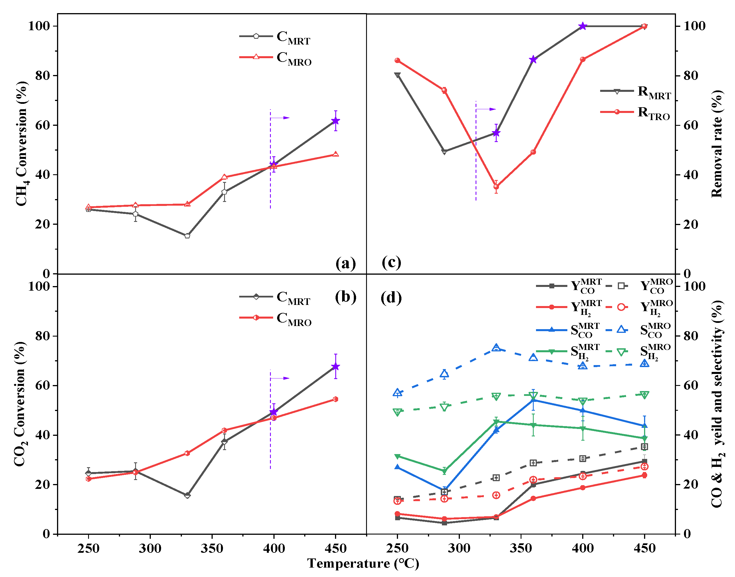
In the plasma–catalytic process, dry reforming of CH4 and benzene removal were studied simultaneously because interactions between the two processes were hypothesized to exist. To further understand the effect of tar addition on DRM and of CH4 and CO2 introduction on tar removal, CH4–CO2 reforming reactions with and without tar introduction and tar removal were carried out under N2 or a gas mixture of CH4, CO2 and N2 at various temperatures (MRT: CH4 dry reforming with tar addition, MRO: CH4 dry reforming only, TRO: tar removal only), with the results shown in Figure 2. For CH4–CO2 reforming in the presence of tar (MRT), CCH4 and CCO2 decreased first with increasing temperature, reached the lowest value at 330 °C and then increased significantly; CH4–CO2 reforming in the absence of tar (MRO) showed that CCH4 and CCO2 monotonically and gradually increased with increasing temperature. The former behaviour suggested that CH4–CO2 reforming and tar removal in the low−temperature zone (250–330 °C) mainly depended on gas−phase reactions excited by plasma and the discharge intensity may have dropped with increasing temperature [2,39]. In the high−temperature regime (330–450 °C), CH4–CO2 reforming is a strongly endothermic reaction, which could be enhanced with increasing reaction temperature. Moreover, the catalyst interacted with plasma to form a synergy significantly enhanced by high temperature, thus greatly improving the reforming performance [40,41]. CCH4 reached maxima of 68% and 54% at 450 °C for two different cases: MRT and MRO, respectively. Significantly, the tar removal results were similar to the CH4–CO2 reforming results achieved under MRT; that is, the tar removal rate decreased at low temperatures and significantly improved at high temperatures.
For the interaction between CH4–CO2 reforming and tar removal, the results showed that the addition of tar significantly changed the CH4–CO2 reforming process, which was divided into two stages. At 288–400 °C, the CCH4 and CCO2 values for MRT were lower than the conversion achieved with MRO. However, upon increasing the temperature to 400–450 °C, the addition of benzene effectively improved the CH4–CO2 reforming performance: CCH4 increased from 48.2% to 61.8% (~14% increase) and CCO2 increased from 54.5% to 67.7% (~13% increase). Interestingly, a similar situation was observed for tar removal. The Rtar for MRT was lower than the value obtained by TRO in the low−temperature range (250–320 °C); when the temperature reached 320–450 °C, the presence of CH4 and CO2 significantly improved the tar removal effect and the maximum value was approximately 37% at 360 °C. There was a mutual promotion effect between CH4 dry reforming and tar removal at high temperatures.
Although CH4 and CO2 exhibited high conversion rates at high temperatures with tar addition, the yield and selectivity for H2 and CO were significantly reduced by tar addition (Figure 2d); this may indicate that the pollution of the catalyst was mainly caused by two factors. First, there was a competition between aromatic compounds and CH4/CO2 gases for active sites, which led to fewer catalytic conversion opportunities for DRM. Free radicals and the active components were generated from CH4 and CO2 activated by plasma, which may recombine with aromatic compounds to give low yield and selectivity for H2 and CO; additionally, the generation of H2 involved benzene decomposition, thus leading to the low yield for H2. Second, deposition of carbon generated by aromatic ring cracking on the catalyst active sites affected the performance of the catalyst and its ability to selectively catalyse CH4–CO2 reforming [42]. From the above experimental results, there was a phenomenon worth exploring under MRT experimental conditions, as shown in Figure 2e. When the temperature was increased from 250 °C to 330 °C, the reactants’ (CH4, CO2, tar) conversion decreased, while the CO and H2 selectivity increased from ~27% to ~42% and ~32% to ~45%, respectively; as the temperature was further increased to 450 °C, the reactants’ conversion increased significantly, while H2 selectivity showed a decrease from ~45% to ~38%. Wang et al. [2] similarly observed that the reactants’ conversion first decreased and then increased with increasing temperature. Their further studies found that the mean electron energy of plasma decreased with increasing temperature and low−energy electrons were unable to break the molecular bonds of the reactants, resulting in lower products yield. They concluded that the synergistic effect of plasma catalysis was dominant at low temperature (250 °C), while the catalyst played a leading role at high temperature (550 °C) rather than the plasma. Wang et al. [39] observed that the increase in temperature negatively affected the dielectric coefficient of the medium, leading to a reduction in discharge strength. In the plasma–catalytic process at 330 °C, the lowest catalytic activity revealed an unsatisfactory plasma–catalyst synergy at 330 °C. High products selectivity implied that 330 °C was the trigger temperature for catalyst activity. However, the selectivity decreased when the temperature was increased to 450 °C. To further understand the catalytic behaviour of the reaction process, the fresh and spent catalysts were characterised. Figure S2 shows the TEM diagrams and the corresponding particle size distributions of the catalysts. The results showed that the particle size distribution at 330 °C remained almost constant compared to the fresh catalyst, but there was a small amount of particle sintering; a large amount of particle sintering occurred at 450 °C and the catalyst particles tended to agglomerate into larger particles, resulting in a decrease in the distribution of active sites, which was not conducive to mass transfer [43]. Figure S3b−e shows high−resolution C 1s XPS data for the spent catalysts and the results of peak deconvolution, with the relative contents of all the peaks of the spent catalysts listed in Table S1. The broad peak was deconvoluted into the peaks for graphitic carbon (C−C peak, at 284.8 eV), carbon bound to oxygen (C−O from hydroxyl or phenol at 286.54 eV and C=O from carboxyl at 288.86 eV) and the shakeup transition of aromatic carbons (π–π* transition, at 290.92 eV) [44,45]. For the MRT experiment conducted at 330 °C, the relative content of aromatic carbon (290.92 eV) reached 10.1%, considerably higher than the value of 2.8% achieved at 450 °C; this corresponded to the experimental results presented in Figure 2c, indicating that there were more aromatic compounds adsorbing to the catalyst surface. Moreover, the sample acquired under MRT at 330 °C exhibited a remarkable O relative content (66.5%), which was higher than the value obtained at 450 °C, which may be attributed to the high selectivity of the catalyst at 330 °C.
According to the results shown in Figure 2f, the H2/CO molar ratios achieved by MRO were lower than 1 over the entire temperature range, which may be attributed to the reverse water gas shift reaction (RWGS, Equation (2)). It is noteworthy that the ratios obtained at low temperatures were higher than those obtained at high temperatures, mainly because the CH4 decomposition reaction, Equation (3), was favoured at low temperatures, while the carbon gasification reaction, Equation (4), was accelerated at high temperatures. Compared with MRO, the H2/CO molar ratios for MRT increased significantly at low temperatures while they were nearly constant at high temperatures. In the DRM reaction, the adsorption and dissociation of CH4 typically occurred on metal active sites, while CO2 showed a preference for adsorbing at the metal–support interfacial sites [46]. In addition, Table S2 shows the H2 molar flow from different reactions (MRT, MRO, TRO) at 250~330 °C. It can be seen that the ratios of H2 molar flow (MRO’s/TRO’s) at different temperatures were close to 10:1, indirectly indicating that H2 production under MRT was mainly from the CH4 cracking reaction, while the tar cracking reaction contributed little. Thus, higher H2/CO ratios at low temperatures may reveal that the addition of benzene aggravates the competitive adsorption through the occupation of the metal–support interfacial sites, which may result in a lower CO yield.
CO2 + H2 → CO + H2O △H0298K= + 41.2 kJ/mol
CH4 → C + 2H2 △H0298K= + 74.6 kJ/mol
C + CO2 → 2CO △H0298K= + 172.5 kJ/mol
Dry reforming of CH4 and tar removal at 450 °C were significantly mutually promoting over the plasma–catalytic process: CCH4 and CCO2 were increased by ~13% with the presence of tar and the tar was completely removed when CH4 and CO2 were introduced. To further understand the mutual promotion effect, the physicochemical properties of the spent catalysts after 2 h of the MRO, TRO and MRT reactions at 450 °C were characterized by TGA, Raman, FTIR, XPS, N2−physisorption, SEM and TEM techniques. This section discusses the effect of tar addition on CH4–CO2 reforming and the effect of CH4 and CO2 introduction on tar removal.
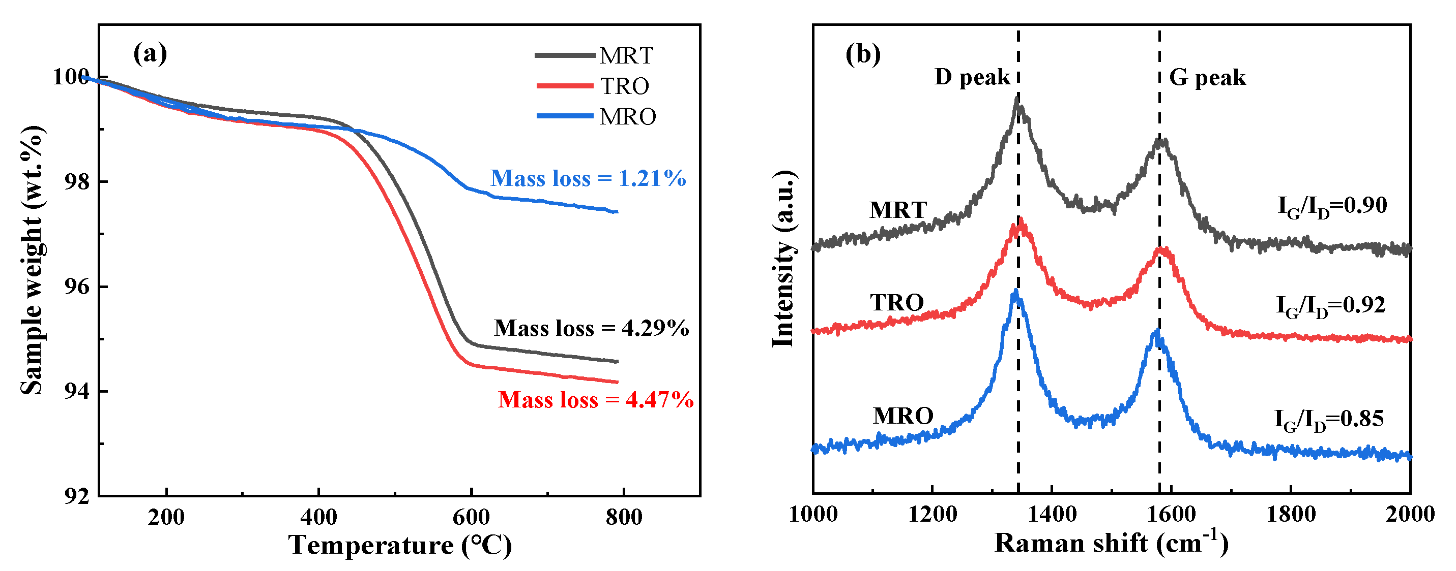
For the effect of tar addition on dry reforming of CH4, the TGA profiles for the spent catalysts are shown in Figure 3a. After the introduction of benzene, the carbon content of the catalyst increased from 1.21% to 4.29%, which may significantly increase the risk of excessive carbon deposits on the active sites, hindering the adsorption of CH4 and CO2 on activated Ni/La metal particles. Figure 3b shows the Raman spectra for the spent catalysts. Two peaks located at 1340 and 1580 cm−1 are observed in the Raman spectrum, corresponding to the D and G bands of carbon, respectively [47]. The D and G bands are due to the vibrations of sp3 disordered carbon and the vibrations of the completely graphitized sp2 structure, respectively [48]. The ratio of G−band intensity and D−band intensity (IG/ID) indicated graphitization of the carbon species. A higher IG/ID value implies a greater degree of graphitization on the catalyst surface [49]. Figure 3b indicates that both disordered carbon and graphitized carbon were formed during the DRM reaction. The catalyst obtained from MRO exhibited the minimum IG/ID ratio, indicating that more defects were generated in the amorphous carbon, which may be beneficial for the adsorption and activation of reactants.
The FTIR spectra of the spent catalysts are shown in Figure S3a. According to the literature [50,51], the bands between 3429 and 3422 cm−1 are attributed to stretching vibrations of hydroxyl (O−H) groups. The weak peaks located at 2919 cm−1 represented C−H stretching vibrations for the cycloalkanes. A peak for C=C stretching vibrations appeared at 1600 cm−1, which was due to the presence of olefins and aromatic rings [52]. Notably, the hydroxyl (O−H) vibrations were evident for the catalysts obtained from MRT and MRO, mainly due to the combination of H radicals and O radicals obtained from CO2 and CO. A weak hydroxyl (O−H) vibrational peak was found for the TRO catalyst, mainly because of the adsorption of moisture from the air. Further illustration from the side showed that the hydroxyl (O−H) vibrational peaks for MRO and MRT were not from moisture.
As observed from the relative contents of the functional groups (Table S1), the C−C peak percentage for MRO was 27.4% and increased to 48.5% with tar addition, which was consistent with the results of the TGA. Notably, the relative contents of O (C−O and C=O) for MRO dropped from 70.3% to 48.6% (~21.7% decrease) when tar was added, further suggesting that the presence of benzene weakened the adsorption of CO2 or oxygen−reactive species on the catalyst surface. More oxygen−active species were present in the gas phase and involved in the reaction of benzene derivatives. Therefore, it could be concluded that there was a bi−channel reaction path for CH4−CO2 reforming. First, CH4 and CO2 adsorbed on the catalyst surface were dissociated and excited by the plasma, inducing the formation of activated molecules and active oxygen species, which may react with carbon deposits or benzene derivatives. Second, CH4 and CO2 were activated directly in the gas phase by plasma, generating radicals that collide with benzene ring macromolecules or recombine with other reactant fragments. Although this was a faster reaction rate than the single−channel reaction pathway of MRO to improve CH4 and CO2 conversion, it came at the expense of H2 and CO yield.
For the effect of CH4 and CO2 introduction on tar removal, as shown in the TGA profiles, the ~4.29% mass loss measured for the MRT process was lower than that for the TRO, suggesting that the introduction of CH4 and CO2 inhibited carbon deposition and released the active sites of the catalyst. In addition, from the Raman spectra results, the highest IG/ID ratio was exhibited by TRO, revealing that the presence of CH4 and CO2 mitigated graphitization and prevented catalyst deactivation due to severe graphitization. The hydroxyl (O−H) vibrational peak seen in the FTIR spectra was hardly found for the TRO catalyst but was remarkable after CH4 and CO2 were introduced; this indicated enhanced oxidation reactions in carbonaceous species, a claim that was supported by the TGA data. Additionally, the relative contents of O (48.6% for MRT > 30.4% for TRO) were consistent with the FTIR data, further confirming the beneficial effects obtained by the introduction of CH4 and CO2. It should be noted that the existence of O in TRO was due to the inevitable oxidation of the sample upon exposure to air during preparation. The general trend (68.3% for TRO > 48.5% for MRT) for the C−C peaks from graphitic carbon was consistent with the results of the Raman analysis shown in Figure 3a.
As shown in Table S3, the La−Ni/γ−Al2O3 catalyst exhibited a smaller specific surface area (97.445 m2·g−1) than its unpromoted counterpart (99.114 m2·g−1). The slightly decreased surface area indicated that the La nanoparticles were most likely well−dispersed on Al2O3 [53]. The BET specific surface area, total pore volume and average pore size of the spent catalysts were slightly lower compared with those of the fresh catalysts, indicating some partial blockage of the pores caused by the carbon deposits. Figure S4a shows that the fresh Ni/γ−Al2O3 and the La−Ni/γ−Al2O3 catalysts exhibited similar Type IV N2 adsorption–desorption isotherms with typical H1 hysteresis loops, indicating that the addition of La did not change the mesoporous structure of the Al2O3 support. Ma et al. [53] found a similar result. In addition, the spent catalysts obtained under different reaction conditions were also analysed, exhibiting similar results (Figure S4b). This result demonstrated well−developed mesopores, despite such severe reaction conditions (simultaneous reactions with ~35 W DBD power at ~450 °C for 2 h). Figure S4c,d shows that the BJH pore width distributions for fresh and spent catalysts were concentrated within the range of 2–20 nm and the largest mesopore size was ~9 nm, i.e., in the low mesoporous range. Notably, Figure S4c shows that the number of centrally distributed pores for the La−Ni/γ−Al2O3 catalyst decreased slightly compared with those of the Ni/γ−Al2O3 catalyst. This was probably due to La particle modifications occurring during the impregnation step.
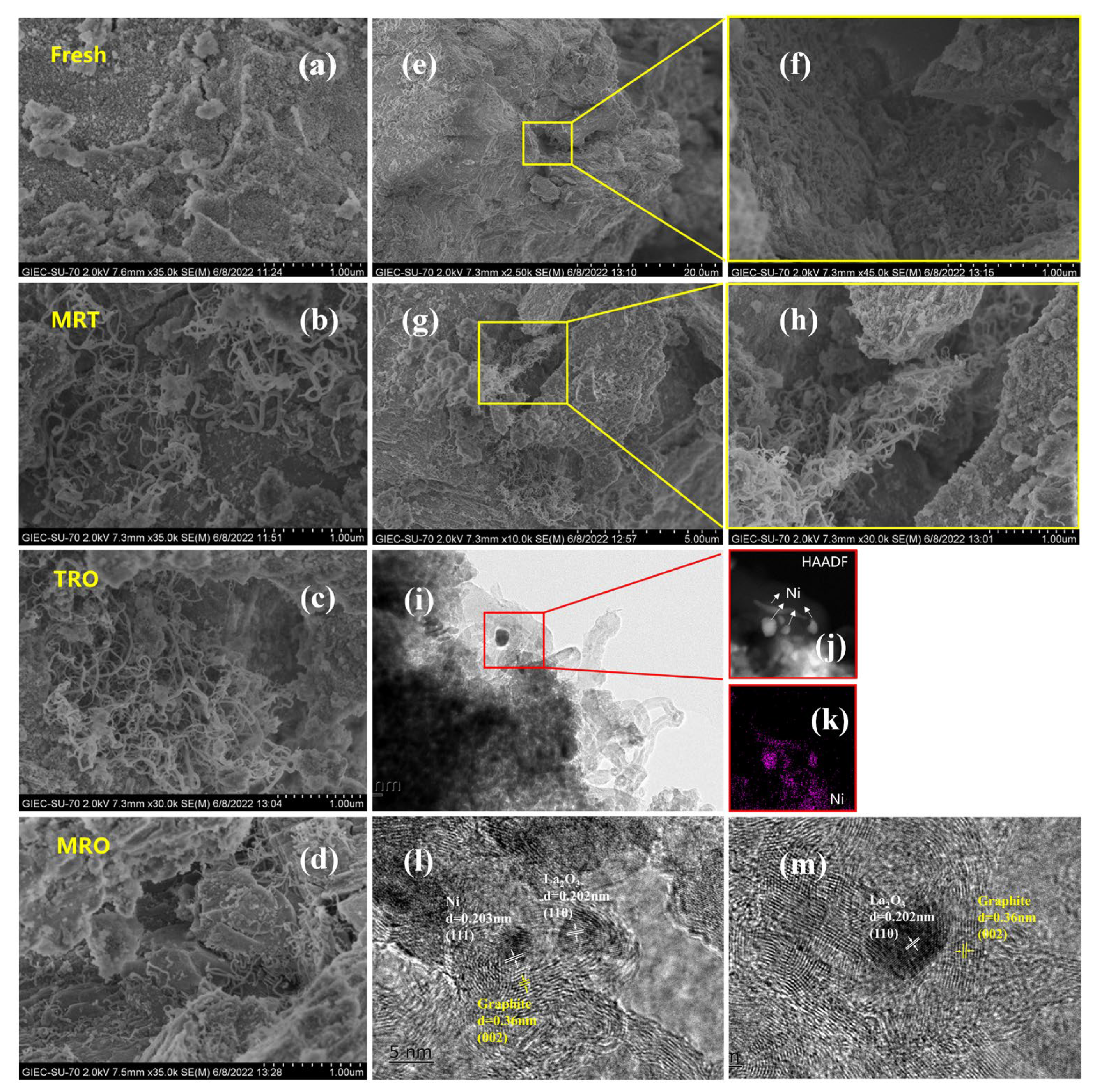
The SEM images of the fresh and spent catalysts (Figure 4a–h) show that the fresh catalyst exhibited spherical nanoparticles and that the spent catalyst surfaces were covered with filamentous carbon nanotubes. Together with the Raman analysis (Figure 3a), the presence of this filamentous carbon may indicate the high degree of graphitization [54]. Zhang et al. [55] investigated the performance of pure lanthanum nickelate (LNO) under plasma–DRM reaction. They found that the nanofibrous carbon deposition observed in the SEM image can be ascribed to the temperature rise and improved conversion for the catalyst [56]. Significantly, compared with the catalysts from MRT and MRO, abundant filamentous carbon was observed from the TRO process. Combined with Raman and TGA characterization data, this revealed that the filamentous carbon was mainly due to benzene decomposition; additionally, it may result in catalyst breakdown and blocking of the active sites via growth in the channels and pores on the catalyst surface, as observed in Figure 4e–h [57]. Figure 4i–k shows the TEM and HAADF images and EDX elemental maps of the spent catalyst for TRO. The Ni metal sites were covered by filamentous carbon nanotubes, causing the separation of Ni from the support and suggesting that carbon was formed at the Ni–support/promoter interface [58]; this confirmed that the addition of benzene aggravated competitive adsorption through occupation of the metal–support interfacial sites. It is important to note that a few hollow filaments were observed in Figure 4i. Snoeck et al. [59] reported similar observations and suggested that hollow filaments were formed with a high carbon nucleation rate. A similar phenomenon was found in other studies, suggesting the occurrence of the tip−growth mechanism on the Ni sites [60,61].
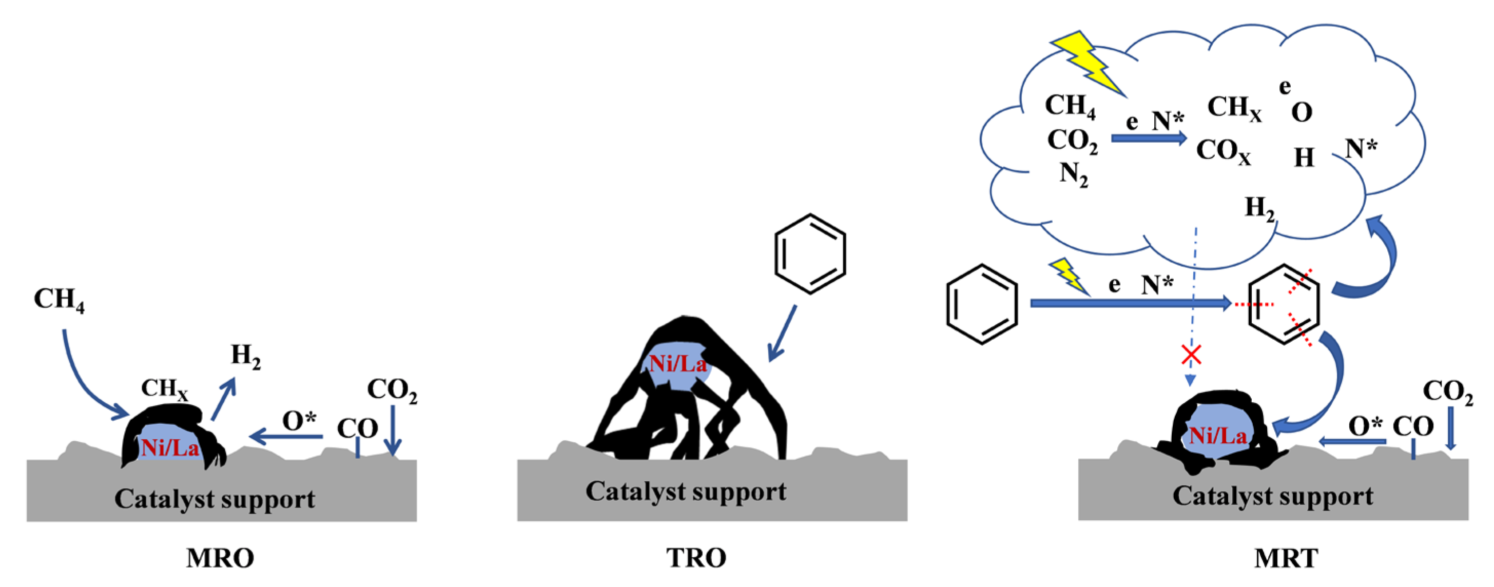
Figure 4d shows that the catalyst obtained under MRO exhibits strong nanoparticle aggregation and encapsulated graphitic carbon on the particle surface. In fact, relative to filamentous carbon, encapsulated graphitic carbon was the major cause of catalyst deactivation [62], because it could encapsulate the Ni active sites, making Ni inaccessible to the reactants. Wu et al. [63] found that the activation of CH4 preferentially reacted on the exposed active Ni metal surface. Thus, the encapsulated graphitic carbon most likely was generated by the activation and decomposition of CH4. Furthermore, Figure 4l,m shows the FFT–HRTEM images and phase identification for the spent catalyst obtained from the MRO process. From the FFT–HRTEM images, Ni and La2O3 were identified with the interplanar distances of 0.203 nm and 0.202 nm for the (111) and (110) lattice planes, respectively. It is worth noting that the presence of La in the catalysts mainly existed in the form of La2O3 before and after the reaction. Xu et al. [64] concluded that the La−O bond is very stable and unable to be reduced below 900 °C. In addition, the HRTEM image indicated the presence of a phase derived from graphitic carbon with an interplanar distance of 0.36 nm for the (002) lattice plane, indicating that the formation of encapsulated graphitic carbon occurred to the same extent for both La2O3 and Ni, which revealed that La2O3 was active for reactants in DRM and promoted the carbon generation reactions (CH4 cleavage or CO disproportionation). Some studies have shown that the basic nature of La2O3 significantly facilitated the adsorption of CO2 and the breaking of C=O bonds during DRM [65]. Figure S3f,g shows La 3d spectra and Ni 2p spectra for the spent catalyst obtained under MRO, from which it was found that the valence state of La was +3 and its main forms were La2O3 and La2(CO3)3 at 834.8 [66] and 835.5 eV, respectively. The satellite peak of La2(CO3)3 was at 839.11 eV and the ∆E between the satellite peak and La 3d5/2 peak was ~3.5 eV, which was the characteristic feature of the La3+ in the state of La2(CO3)3 [67]. The formation of La2(CO3)3 was attributed to the interaction between La2O3 and CO2 [68]. In addition, ~852.3, ~853.6, ~855.3 and ~856.2 eV correspond to Ni0 [53], Ni2+ (NiO) [53], Ni2+ (Ni(OH)2) [69] and Ni2+ (NiAl2O4) [67], respectively, of which the spinel peak was the strongest. A sharp spinel peak indicated the strong Ni−Al interaction formation; most of the Ni0 converted to Ni2+ due to the presence of CO2 in the reaction atmosphere. There was a peak at ~850.22 eV related to La 3d3/2 region, which was at an overlap between La and Ni peaks. For the catalyst obtained from MRT (Figure 4b), no encapsulated graphitic carbon was observed on spherical nanoparticles and slightly filamentous carbon scattered on the catalyst surface was observed. This phenomenon can be attributed to a mutual promotion effect between CH4–CO2 reforming and benzene removal. First, the O involved in the CO2 decomposition reduced the extent of filamentous carbon formation. Second, the benzene fragments were dissociated and converted into viable molecules through plasma catalysis and reacted with CHX, efficiently inhibiting the formation of encapsulated graphitic carbon. The relevant reaction mechanism is shown in Figure 5.

2.3. Reaction Mechanism Analysis

To reveal the possible reaction pathways and mechanisms for benzene destruction in the plasma catalytic process, the collected liquid byproducts and their structures are listed in Figure S5 and Table S4.
Studies of simultaneous CH4 dry reforming and benzene removal in the plasma reactor are complex due to the formation of free radicals, active molecules and ions [70]. A proposed reaction mechanism was based on the detection of liquid byproducts and the most thermodynamically favourable reactions [71]. The GC–MS analysis results shown in Figure S5 and Table S4 reveal the effects of pure N2 and the gas mixture (N2, CH4 and CO2) on the liquid phase byproduct distribution produced during tar removal. The distribution of byproducts from the gas mixture was similar to that of the pure N2 atmosphere and mainly included aromatic hydrocarbons, aliphatic hydrocarbons and oxygen−containing compounds. The presence of aliphatic hydrocarbons proved the operation of a ring−opening reaction involving benzene and an intermediate of benzene. After the electron impact−induced dissociation of N2 in the reaction system, excited nitrogen molecules N2* were generated initially (Equation (5)). The destruction of benzene was caused by direct attack of energetic electrons and N2*. The chemical binding energies determine the order in which different chemical bonds are destroyed. The C−H binding energy of the methyl group on the benzene ring is 3.7 eV, the C−H binding energy on the aromatic ring is 4.3 eV, the C−C binding energy between the aromatic ring and methyl group is 4.4 eV, the C−C binding energy on the aromatic ring is 5.0–5.3 eV, the binding energy of C=C is 5.5 eV and the average energy of electrons generated by ionization of macromolecules after energetic electron bombardment by plasma ranges from 1–10 eV, which provides a good dissociation and activation environment for the whole reaction system; thus, it becomes easier to realize chemical reactions that are difficult to achieve under normal conditions. In the plasma reaction, there are two main destructive ways to remove benzene: (a) benzene is directly attacked by energetic electrons and undergoes ring opening or (b) the benzene ring is bombarded by energetic electrons and N2* to form phenyl, which reacts with active species to form new aromatic compounds.
N2 + e → N2* + e
Possible reaction pathways for benzene reforming under a N2 atmosphere are shown in Figure 6a. After bombardment by energetic electrons and N2*, benzene is first converted to phenyl because the dissociation energy of the C−H bond is the smallest in the benzene molecule [72]. Therefore, cracking of benzene can occur through this path to generate phenyl and then phenyl recombines with a methyl radical to form toluene. Toluene is the most abundant liquid−phase byproduct after benzene, which indicates that it is on the main path of forming liquid−phase byproducts. The generated toluene can also be used as a raw material for the formation of other liquid−phase byproducts, such as ethylbenzene and trans decahydronaphthalene. In addition, the C−C bond on the benzene ring can also be dissociated by energetic electrons, resulting in the formation of the HC=CH biradical and cyclobutadiene. The biradical HC=CH finally forms ethylene and cyclobutadiene can be used as a raw material for the production of naphthalene. However, no naphthalene peak was detected via GC–MS, indicating that in this reaction system full of energetic electrons, naphthalene finally generated trans−decahydronaphthalene through hydrogen reduction. The biradical HC=CH, produced by the dissociation of a C−C bond from the benzene ring, can be used as the raw material for the production of styrene. In addition, energetic electrons may also promote complete decomposition of benzene rings and intermediate compounds of benzene to produce methyl radicals and linear hydrocarbons, which was confirmed by the detection of n−heptane and n−decane via GC–MS.
A possible reaction pathway for reforming benzene under a gas mixture is shown in Figure 6b. CH4 and CO2 gas molecules collide with energetic electrons and N2* to form CHX, H, O, CO and H2 free radicals or active molecules (Equations (6)–(11)), which increases the concentration of active substances in the reaction system and greatly improves the chance of reactions between active components and other reactants. CO2 dissociates under the action of energetic electrons and introduces O active species [73]. According to the GC–MS results, unlike benzene reforming under a N2 atmosphere, benzene removal under a gas mixture produces the oxygen−containing compound 2−butyl acrylate, which indicates that after ionization in the discharge area, O radicals participated in the reaction and the oxygen active particles obtained from collisions of energetic electrons with CO2 molecules were recombined with the cracked fragments from benzene. In addition, the concentrations of toluene, ethylbenzene and styrene in the liquid phase byproducts obtained under the gas mixture were higher than those seen for the pure N2 atmosphere, which can be explained by the increased concentrations of methyl and H radicals produced under the gas mixture. The concentration of benzene was lower than that seen in the pure N2 atmosphere because benzene is more likely to be destroyed or reconstituted under the gas mixture than under the pure N2 atmosphere.
CH4 + e/ N2* → CH3 + H + e/N2
CH4 + e/ N2* → CH2 + H2 + e/N2
CH4 + e/ N2* → CH + H + H2 + e/N2
CH4 + e/ N2* → C + 2H2 + e/N2
CO2 + e/ N2* → CO + O + e/N2
CO2 + CH4 → 2CO + 2H2

3. Materials and Methods

3.1. Catalyst Preparation

The 2%La−10%Ni/γ−Al2O3 catalyst was prepared by an equal−volume impregnation method. The appropriate weight of γ−Al2O3 (160–200 items) was added to the metal precursor solution (Ni(NO3)2·6H2O and La(NO3)2·6H2O) and impregnated for 24 h. The above solution was dried at 105 °C until most of the water evaporated. Then, the obtained samples were calcined at 600 °C for 4 h in air atmosphere.

3.2. Experimental Setup

The experiments were carried out in a coaxial DBD reactor (Figure S6). The dielectric barrier discharge (DBD) plasma reactor was composed of a cylindrical aluminium tube (i.d.: 20 mm, o.d.: 25.8 mm) wrapped with stainless steel mesh in the middle of the tube. A stainless−steel bar (diameter 14 mm), which served as the inner electrode, was placed along the axis of the tube and a layer of steel mesh (thickness 2 mm, diameter 20 mm) was fixed at the bottom of the bar as a reaction bed support. The plasma was generated in the annular space between the coaxial cylindrical tubes. The corresponding discharge distance was 3 mm and the discharge volume was 16.02 mL. During the experiments, the La−Ni/γ−Al2O3 catalyst was placed in the discharge space.
The reaction temperature was controlled by a temperature controller and measured with a K−type thermocouple during the experiments. Before the reactions, the catalyst was reduced by pure hydrogen at 600 °C for 2 h. The DBD reactor was powered by an AC high−voltage power supply (Nanjing Suman Plasma Technology Co., CTP−2000K, Nanjing, China) with a peak voltage of 30 kV and a frequency of 5–20 kHz. In this research, the average input power and the frequency were 35 W and 7 kHz, respectively. The high voltage applied to the DBD was measured with a high voltage probe (Tektronix, p6015a, Beaverton, OR, USA). A capacitor (0.1 μF) was connected between the outer electrode of the reactor and the grounding electrode and all electrical signals were recorded with a digital oscilloscope (Tektronix, DPO2024B, Beaverton, OR, USA). The V−Q Lissajous method was used to determine the ability to discharge the reactor and then calculate the discharge power by multiplying the area of Lissajous by the frequency.
In the experiments, the gases (99.999% purity) were provided by high−pressure cylinders with the flow rates controlled by a mass flow controller (Beijing Seven Star Huachuang Flowmeter Co., D07, Beijing, China). Benzene vapour (9000 ppmv) was introduced into the reactor by using a nitrogen carrier gas that had flowed through a benzene−containing bubbler, which was placed in a water bath at a temperature of 40 °C. The heating belt was wrapped along the gas pipeline to ensure vaporisation of the benzene. The benzene, carried by the nitrogen stream and carrier gas (N2:CO2:CH4 = 2:1:1), was fully mixed with the gas stream in the mixing chamber before feeding into the DBD reactor. The total flow rate and the concentration of benzene were kept at 300 mL/min (based on room temperature and atmospheric pressure) and 9000 ppmv (29.6 g/m3), respectively. At the outlet, the gas stream passed through an absorption bottle placed in an ice water bath and the flow rate was determined by a soap film flow meter. Unless otherwise stated, the tar discussed in this work is the tar model compound benzene.

3.3. Method of Analysis and Definition of Parameters

The composition of the produced gas was analysed with a gas chromatograph (GC, Shimadzu Corporation, GC−2014, Kyoto, Japan) equipped with a flame ionization detector (FID) for analyses of C1–C4 hydrocarbons and a thermal conductivity detector (TCD) used to analyse H2, CO, CO2 and CH4. During the experimental process, the exhaust gas was introduced to an absorption bottle filled with 75 mL of hexane, which was placed in an ice water bath to collect the liquid products. The liquid products were analysed with an off−line gas chromatography–mass spectrometry system (GC–MS, Thermo Fisher Scientific (China) Co., Trace 1300−ISQ, Shanghai, China) equipped with a DB−5 capillary column. The exhaust gas was collected after running the DBD for 20 min when the reaction reached a stable situation.
For the CH4 dry reforming reaction, the conversion rates for CH4 and CO2 were defined as
C C H 4 % =   moles   of   C H 4   converted   m m o l / s   moles   of   C H 4   input   m m o l / s × 100 % ,
C C O 2 % =   moles   of   C O 2   converted   m m o l / s   moles   of   C O 2   input   m m o l / s × 100 %   ,
The selectivity, S, and yield, Y, of the products can be calculated as
S H 2 % =   moles   of   H 2   produced   m m o l / s 2 ×   moles   of   C H 4   converted   m m o l / s + 3 ×   moles   of   C 6 H 6   converted   m m o l / s × 100 % ,
S C O % =   moles   of   C O   produced   m m o l / s   moles   of   C O 2   converted   +   moles   of   C H 4   converted   + 6 ×   moles   of   C 6 H 6   converted   × 100 % ,
Y H 2 % =   moles   of   H 2   produced   m m o l / s 2 ×   moles   of   C H 4   input   m m o l / s + 3 × m o l e s   of   C 6 H 6   input   m m o l / s × 100 %   ,
Y C O % =   moles   of   C O   produced   m m o l / s   moles   of   C O 2   input   +   moles   of   C H 4   input   + 6 ×   moles   of   C 6 H 6   input   × 100 % ,
The H2/CO molar ratio was defined as
H 2 C O =   moles   of   H 2   produced   m m o l / s   moles   of   C O   produced   m m o l / s ,
The tar removal efficiency was calculated as follows:
R t a r % =   amount   of   benzene   converted   g / m i n   amount   of   benzene   input   g / m i n × 100 % .

4. Conclusions

There was a certain mutual promotion effect operating between CH4–CO2 reforming and tar removal in the high−temperature range, as indicated by reactant conversion (~13% increase for CCH4 and CCO2 at 450 °C in the presence of tar and a ~37% increase for the tar removal rate at 360 °C when CH4 and CO2 were introduced). Strictly speaking, the reinforcing effect of CH4 dry reforming was only understood to be the effectiveness of CH4 and CO2 conversion. The mutual promotion effect between CH4 dry reforming and tar removal can be classified into two aspects:
  • For CH4–CO2 reforming, the addition of benzene affected the physicochemical properties of the catalyst surface. The excessive graphitic carbon caused encapsulation of the active sites or coverage of the defective sites, which weakened the adsorption of CO2 and CH4. In addition, the addition of benzene increased the gas−phase reaction density by generating ring−opening products and benzene radicals via the plasma action, which reacted or recombined with the active components (CHX, H, H2, CO, O) that originated from CH4 and CO2.
  • For tar removal, the introduction of CH4 and CO2 improved the catalyst surface activity by increasing the concentration of reactive oxygen species on the catalyst surface, which in turn increased the resistance of the catalyst to graphitization and carbon deposits. This further enhanced the oxidation of carbonaceous species on the catalyst surface and facilitated the cracking of benzene to gas phase products (CO, CO2) via indirect or direct reaction pathways. On the other hand, the introduction of CH4 and CO2 may increase the amount of H, O, H2 and COX in the gas phase by plasma action, facilitating benzene reforming and ring−opening reactions; for example, benzene radicals recombine with CHX to form other aromatic compounds (e.g., toluene, ethylbenzene and styrene).
Finally, although several reasons for the mutual promotion of tar removal and CH4 dry reforming have been summarized, there is still some work that needs to be further investigated. For example, the effects of benzene, CH4 and CO2 on the plasma system, such as changes in the discharge morphology or discharge patterns due to changes in the electrical conductivity, have not yet been investigated and will be carried out in future work.

Supplementary Materials

The following supporting information can be downloaded at https://www.mdpi.com/article/10.3390/catal13040686/s1: Figure S1. XRD analyses of the La−Ni/γ−Al2O3 catalyst calcined at 600 °C; Figure S2. TEM analysis and particle size distributions for fresh catalyst and spent catalysts after 2 h reaction at 330 °C and 450 °C; Figure S3. (a) FTIR spectra, (b−e) C 1 s spectra and relative contents of functional groups for spent catalysts under different conditions, and (f) La 3d spectra and (g) Ni 2p spectra for spent catalyst under MRO at 450 °C; Figure S4. (a, b) N2 adsorption−desorption isotherms and (c, d) BJH pore width distributions for fresh and spent catalysts; Figure S5. GC–MS spectrogram of benzene removal under a gas mixture (N2, CH4 and CO2) atmosphere and a pure N2 atmosphere; Figure S6. Schematic diagram of the experimental setup; Table S1. Relative contents of the peaks of the spent catalysts; Table S2. H2 molar flow from plasma−coupled catalytic processes; Table S3. Catalyst characterization data; Table S4. Main products identified in the liquid sample by GC–MS.

Author Contributions

Conceptualization, B.X., L.L., W.Y. and H.Z.; Methodology, W.H.; Software, W.H. and B.X.; Validation, B.X.; Formal analysis, W.H., B.X., L.L. and H.L.; Investigation, B.X., L.L., W.Y. and H.L.; Resources, J.X.; Data curation, W.H.; Writing—original draft preparation, W.H.; Writing—review and editing, B.X., H.Z. and J.X.; Visualization, W.H.; Supervision, J.X., X.Y. and C.W.; Project administration, J.X. and X.Y.; Funding acquisition, B.X., J.X. and X.Y. All authors have read and agreed to the published version of the manuscript.

Funding

This research was funded by the National Key R&D Program of China (Grant No. 2019YFB1503902), the National Natural Science Foundation of China (Grant No. 52106282), the Strategic Priority Research Program of Chinese Academy of Sciences (Grant No. XDA21060600), the Science and Technology Program of Guangzhou (Grant No. 202002030126 and Grant No. 202102020292) and the High−tech Industrialization Project of Science and Technology Cooperation between Jilin Province and Chinese Academy of Sciences (Grant No. 2021SYHZ0014).

Data Availability Statement

The data are included in the article or Supplementary Materials.

Conflicts of Interest

The authors declare no conflict of interest.

References

  1. Molino, A.; Chianese, S.; Musmarra, D. Biomass gasification technology: The state of the art overview. J. Energy Chem. 2016, 25, 10–25. [Google Scholar] [CrossRef]
  2. Wang, W.T.; Ma, Y.; Chen, G.X.; Quan, C.; Yanik, J.; Gao, N.B.; Tu, X. Enhanced hydrogen production using a tandem biomass pyrolysis and plasma reforming process. Fuel Process. Technol. 2022, 234, 107333. [Google Scholar] [CrossRef]
  3. Sutton, D.; Kelleher, B.; Ross, J.R.H. Review of literature on catalysts for biomass gasification. Fuel Process. Technol. 2001, 73, 155–173. [Google Scholar] [CrossRef]
  4. Heidenreich, S.; Foscolo, P.U. New concepts in biomass gasification. Prog. Energy Combust. Sci. 2015, 46, 72–95. [Google Scholar] [CrossRef]
  5. Lopez, G.; Artetxe, M.; Amutio, M.; Alvarez, J.; Bilbao, J.; Olazar, M. Recent advances in the gasification of waste plastics. A critical overview. Renew. Sust. Energy Rev. 2018, 82, 576–596. [Google Scholar] [CrossRef]
  6. Owgi, A.H.K.; Jalil, A.A.; Hussain, I.; Hambali, H.U.; Nabgan, W. Enhancing resistance of carbon deposition and reaction stability over nickel loaded fibrous silica-alumina (Ni/FSA) for dry reforming of methane. Int. J. Hydrogen Energy 2022, 47, 42250–42265. [Google Scholar] [CrossRef]
  7. Li, C.; Suzuki, K. Tar property, analysis, reforming mechanism and model for biomass gasification—An overview. Renew Sust Energy Rev. 2009, 13, 594–604. [Google Scholar] [CrossRef]
  8. Ren, J.; Cao, J.P.; Zhao, X.Y.; Liu, Y.L. Fundamentals and applications of char in biomass tar reforming. Fuel Process. Technol. 2021, 216, 106782. [Google Scholar] [CrossRef]
  9. Ashcroft, A.T.; Cheetham, A.K.; Green, M. Partial oxidation of methane to synthesis gas using carbon dioxide. Nature 1991, 352, 225–226. [Google Scholar] [CrossRef]
  10. Wang, Y.; Yao, L.; Wang, S.H.; Mao, D.H.; Hu, C.W. Low-temperature catalytic CO2 dry reforming of methane on Ni-based catalysts: A review. Fuel Process. Technol. 2018, 169, 199–206. [Google Scholar] [CrossRef]
  11. Pakhare, D.; Spivey, J. A review of dry (CO2) reforming of methane over noble metal catalysts. Chem. Soc. Rev. 2014, 43, 7813–7837. [Google Scholar] [CrossRef]
  12. Nielsen, N.D.; Thrane, J.; Jensen, A.D.; Christensen, J.M. Bifunctional synergy in CO hydrogenation to methanol with supported Cu. Catal. Lett. 2020, 150, 1427–1433. [Google Scholar] [CrossRef]
  13. Diao, Y.; Zhang, X.; Liu, Y.; Chen, B.; Wu, G.; Shi, C. Plasma-assisted dry reforming of methane over Mo2C-Ni/Al2O3 catalysts: Effects of β-Mo2C promoter. Appl. Catal. B 2022, 301, 120779. [Google Scholar] [CrossRef]
  14. Abiev, R.S.; Sladkovskiy, D.A.; Semikin, K.V.; Murzin, D.Y.; Rebrov, E.V. Non-Thermal Plasma for Process and Energy Intensification in Dry Reforming of Methane. Catalysts 2020, 10, 1358. [Google Scholar] [CrossRef]
  15. Liu, Y.; Song, J.; Diao, X.; Liu, L.; Sun, Y. Removal of tar derived from biomass gasification via synergy of non-thermal plasma and catalysis. Sci. Total Environ. 2020, 721, 137671. [Google Scholar] [CrossRef] [PubMed]
  16. Cimerman, R.; Cibikova, M.; Satrapinskyy, L.; Hensel, K. The Effect of Packing Material Properties on Tars Removal by Plasma Catalysis. Catalysts 2020, 10, 1476. [Google Scholar] [CrossRef]
  17. Kong, X.; Zhang, H.; Li, X.; Xu, R.; Mubeen, I.; Li, L.; Yan, J. Destruction of Toluene, Naphthalene and Phenanthrene as Model Tar Compounds in a Modified Rotating Gliding Arc Discharge Reactor. Catalysts 2019, 9, 19. [Google Scholar] [CrossRef] [Green Version]
  18. Chung, W.-C.; Chang, M.-B. Dry reforming of methane by combined spark discharge with a ferroelectric. Energy Convers. Manage. 2016, 124, 305–314. [Google Scholar] [CrossRef] [Green Version]
  19. Li, S.; Dang, X.; Yu, X.; Abbas, G.; Zhang, Q.; Cao, L. The application of dielectric barrier discharge non-thermal plasma in VOCs abatement: A review. Chem. Eng. J. 2020, 388, 124275. [Google Scholar] [CrossRef]
  20. Eliasson, B.; Liu, C.-j.; Kogelschatz, U. Direct conversion of methane and carbon dioxide to higher hydrocarbons using catalytic dielectric-barrier discharges with zeolites. Ind. Eng. Chem. Res. 2000, 39, 1221–1227. [Google Scholar] [CrossRef]
  21. Tang, Y.; Zhuo, J.K.; Cui, W.; Li, S.Q.; Yao, Q. Enhancing ignition and inhibiting extinction of methane diffusion flame by in situ fuel processing using dielectric-barrier-discharge plasma. Fuel Process. Technol. 2019, 194, 106128. [Google Scholar] [CrossRef]
  22. Wang, L.; Yi, Y.; Wu, C.; Guo, H.; Tu, X. One-step reforming of CO2 and CH4 into high-value liquid chemicals and fuels at room temperature by plasma-driven catalysis. Angew. Chem. Int. Ed. 2017, 56, 13679–13683. [Google Scholar] [CrossRef] [PubMed] [Green Version]
  23. Goujard, V.; Tatibouët, J.-M.; Batiot-Dupeyrat, C. Use of a non-thermal plasma for the production of synthesis gas from biogas. Appl. Catal. A 2009, 353, 228–235. [Google Scholar] [CrossRef]
  24. Ray, D.; Manoj Kumar Reddy, P.; Challapalli, S. Glass beads packed DBD-plasma assisted dry reforming of methane. Top. Catal. 2017, 60, 869–878. [Google Scholar] [CrossRef]
  25. Chung, W.-C.; Chang, M.-B. Review of catalysis and plasma performance on dry reforming of CH4 and possible synergistic effects. Renew Sust Energy Rev. 2016, 62, 13–31. [Google Scholar] [CrossRef]
  26. Mei, D.H.; Liu, S.Y.; Tu, X. CO2 reforming with methane for syngas production using a dielectric barrier discharge plasma coupled with Ni/γ-Al2O3 catalysts: Process optimization through response surface methodology. J. CO2 Util. 2017, 21, 314–326. [Google Scholar] [CrossRef]
  27. Mei, D.; Zhu, X.; He, Y.-L.; Yan, J.D.; Tu, X. Plasma-assisted conversion of CO2 in a dielectric barrier discharge reactor: Understanding the effect of packing materials. Plasma Sources Sci. Technol. 2014, 24, 015011. [Google Scholar] [CrossRef] [Green Version]
  28. Rahemi, N.; Haghighi, M.; Babaluo, A.A.; Jafari, M.F.; Estifaee, P. Plasma assisted synthesis and physicochemical characterizations of Ni–Co/Al2O3 nanocatalyst used in dry reforming of methane. Plasma Chem. Plasma Process. 2013, 33, 663–680. [Google Scholar] [CrossRef]
  29. Zeng, Y.; Zhu, X.; Mei, D.; Ashford, B.; Tu, X. Plasma-catalytic dry reforming of methane over γ-Al2O3 supported metal catalysts. Catal. Today 2015, 256, 80–87. [Google Scholar] [CrossRef]
  30. Khoja, A.H.; Tahir, M.; Amin, N.A.S. Cold plasma dielectric barrier discharge reactor for dry reforming of methane over Ni/(sic)-Al2O3-MgO nanocomposite. Fuel Process. Technol. 2018, 178, 166–179. [Google Scholar] [CrossRef]
  31. Saleem, F.; Rehman, A.; Abbas, A.; Hussain Khoja, A.; Ahmad, F.; Liu, L.; Zhang, K.; Harvey, A. A comparison of the decomposition of biomass gasification tar compound in CO, CO2, H2 and N2 carrier gases using non-thermal plasma. J. Energy Inst. 2021, 97, 161–168. [Google Scholar] [CrossRef]
  32. Liu, J.-L.; Li, X.-S.; Zhu, X.; Li, K.; Shi, C.; Zhu, A.-M. Renewable and high-concentration syngas production from oxidative reforming of simulated biogas with low energy cost in a plasma shade. Chem. Eng. J. 2013, 234, 240–246. [Google Scholar] [CrossRef]
  33. Liu, L.; Wang, Q.; Ahmad, S.; Yang, X.; Ji, M.; Sun, Y. Steam reforming of toluene as model biomass tar to H2-rich syngas in a DBD plasma-catalytic system. J. Energy Inst. 2018, 91, 927–939. [Google Scholar] [CrossRef]
  34. Liu, S.Y.; Mei, D.H.; Nahil, M.A.; Gadkari, S.; Gu, S.; Williams, P.T.; Tu, X. Hybrid plasma-catalytic steam reforming of toluene as a biomass tar model compound over Ni/Al2O3 catalysts. Fuel Process. Technol. 2017, 166, 269–275. [Google Scholar] [CrossRef]
  35. Xu, B.; Xie, J.; Yin, X.; Liu, H.; Sun, C.; Wu, C. Mechanisms of Toluene Removal in Relation to the Main Components of Biosyngas in a Catalytic Nonthermal Plasma Process. Energy Fuels 2019, 33, 4287–4301. [Google Scholar] [CrossRef]
  36. Nair, S.A.; Pemen, A.J.M.; Yan, K.; Van Heesch, E.J.M.; Ptasinski, K.J.; Drinkenburg, A.A.H. Chemical processes in tar removal from biomass derived fuel gas by pulsed corona discharges. Plasma Chem. Plasma Process. 2003, 23, 665–680. [Google Scholar] [CrossRef]
  37. Wnukowski, M.; Jamróz, P. Microwave plasma treatment of simulated biomass syngas: Interactions between the permanent syngas compounds and their influence on the model tar compound conversion. Fuel Process. Technol. 2018, 173, 229–242. [Google Scholar] [CrossRef]
  38. Kondrat, S.A.; Smith, P.J.; Lu, L.; Bartley, J.K.; Taylor, S.H.; Spencer, M.S.; Kelly, G.J.; Park, C.W.; Kiely, C.J.; Hutchings, G.J. Preparation of a highly active ternary Cu-Zn-Al oxide methanol synthesis catalyst by supercritical CO2 anti-solvent precipitation. Catal. Today 2018, 317, 12–20. [Google Scholar] [CrossRef]
  39. Wang, Q.; Yan, B.H.; Jin, Y.; Cheng, Y. Dry Reforming of Methane in a Dielectric Barrier Discharge Reactor with Ni/Al2O3 Catalyst: Interaction of Catalyst and Plasma. Energy Fuels 2009, 23, 4196–4201. [Google Scholar] [CrossRef]
  40. Xu, B.; Xie, J.; Yuan, H.; Yin, X.; Wu, C. Experimental study on benzene removal of fuel gas in a packed-bed dielectric barrier discharge reactor. J. Fuel Chem. Technol. 2019, 47, 493–503. [Google Scholar]
  41. Blackbeard, T.; Demidyuk, V.; Hill, S.L.; Whitehead, J.C. The effect of temperature on the plasma-catalytic destruction of propane and propene: A comparison with thermal catalysis. Plasma Chem. Plasma Process. 2009, 29, 411–419. [Google Scholar] [CrossRef]
  42. Pan, W.; Meng, J.; Gu, T.; Zhang, Q.; Zhang, J.; Wang, X.; Bu, C.; Liu, C.; Xie, H.; Piao, G. Plasma-catalytic steam reforming of benzene as a tar model compound over Ni-HAP and Ni-gamma Al2O3 catalysts: Insights into the importance of steam and catalyst support. Fuel 2023, 339, 127327. [Google Scholar] [CrossRef]
  43. Wang, J.; Zhang, G.; Li, G.; Liu, J.; Wang, Y.; Xu, Y.; Lyu, Y. Understanding structure-activity relationships of the highly active and stable La promoted Co/WC-AC catalyst for methane dry reforming. Int. J. Hydrogen Energy 2022, 47, 7823–7835. [Google Scholar] [CrossRef]
  44. Lu, Z.; Chen, G.; Siahrostami, S.; Chen, Z.; Liu, K.; Xie, J.; Liao, L.; Wu, T.; Lin, D.; Liu, Y. High-efficiency oxygen reduction to hydrogen peroxide catalysed by oxidized carbon materials. Nat. Catal. 2018, 1, 156–162. [Google Scholar] [CrossRef]
  45. Smith, M.; Scudiero, L.; Espinal, J.; McEwen, J.-S.; Garcia-Perez, M. Improving the deconvolution and interpretation of XPS spectra from chars by ab initio calculations. Carbon 2016, 110, 155–171. [Google Scholar] [CrossRef] [Green Version]
  46. Rostrup-Nielsen, J.R.; Sehested, J.; Norskov, J.K. Hydrogen and synthesis gas by steam- and CO2 reforming. In Advances in Catalysis; Gates, B.C., Knozinger, H., Eds.; 2002; Volume 47, pp. 65–139. [Google Scholar] [CrossRef]
  47. Li, W.; Gao, Y.; Chen, W.; Tang, P.; Li, W.; Shi, Z.; Su, D.; Wang, J.; Ma, D. Catalytic epoxidation reaction over N-containing sp2 carbon catalysts. Acs Catal. 2014, 4, 1261–1266. [Google Scholar] [CrossRef]
  48. Zhang, X.; Xu, Y.; Zhang, G.; Wu, C.; Liu, J.; Lv, Y. Nitrogen-doped porous carbons derived from sustainable biomass via a facile post-treatment nitrogen doping strategy: Efficient CO2 capture and DRM. Int. J. Hydrogen Energy 2022, 47, 24388–24397. [Google Scholar] [CrossRef]
  49. Moussa, S.O.; Panchakarla, L.S.; Ho, M.Q.; El-Shall, M.S. Graphene-supported, iron-based nanoparticles for catalytic production of liquid hydrocarbons from synthesis gas: The role of the graphene support in comparison with carbon nanotubes. ACS Catal. 2014, 4, 535–545. [Google Scholar] [CrossRef]
  50. Shafeeyan, M.S.; Daud, W.M.A.W.; Houshmand, A.; Arami-Niya, A. Ammonia modification of activated carbon to enhance carbon dioxide adsorption: Effect of pre-oxidation. Appl. Surf. Sci. 2011, 257, 3936–3942. [Google Scholar] [CrossRef]
  51. Zhang, K.; He, Y.; Wang, Z.; Huang, T.; Li, Q.; Kumar, S.; Cen, K. Multi-stage semi-coke activation for the removal of SO2 and NO. Fuel 2017, 210, 738–747. [Google Scholar] [CrossRef]
  52. Zhang, L.; Yao, Z.; Zhao, L.; Li, Z.; Yi, W.; Kang, K.; Jia, J. Synthesis and characterization of different activated biochar catalysts for removal of biomass pyrolysis tar. Energy 2021, 232, 120927. [Google Scholar] [CrossRef]
  53. Ma, Y.; Su, Z.; Tang, N.; Chen, S.; Wang, W.; Yuan, J.; Cao, Z.; He, H.; Cong, Y. Styrene hydrogenation over Ni–La/Al2O3 catalysts: The impact of added La on active metal dispersion. Chem. Phys. Lett. 2021, 775, 138604. [Google Scholar] [CrossRef]
  54. Cichy, M.; Pańczyk, M.; Słowik, G.; Zawadzki, W.; Borowiecki, T. Ni–Re alloy catalysts on Al2O3 for methane dry reforming. Int. J. Hydrogen Energy 2022, 47, 16528–16543. [Google Scholar] [CrossRef]
  55. Zhang, M.M.; Gao, Y.B.; Mao, Y.P.; Wang, W.L.; Sun, J.; Song, Z.L.; Sun, J.; Zhao, X.Q. Enhanced dry reforming of methane by microwave-mediated confined catalysis over Ni-La/AC catalyst. Chem. Eng. J. 2023, 451, 138616. [Google Scholar] [CrossRef]
  56. Zhang, F.S.; Song, Z.L.; Zhu, J.Z.; Liu, L.; Sun, J.; Zhao, X.Q.; Mao, Y.P.; Wang, W.L. Process of CH4-CO2 reforming over Fe/SiC catalyst under microwave irradiation. Sci. Total Environ. 2018, 639, 1148–1155. [Google Scholar] [CrossRef]
  57. Gao, N.B.; Salisu, J.; Quan, C.; Williams, P. Modified nickel-based catalysts for improved steam reforming of biomass tar: A critical review. Renew. Sustain. Energy Rev. 2021, 145, 111023. [Google Scholar] [CrossRef]
  58. Ochoa, A.; Bilbao, J.; Gayubo, A.G.; Castano, P. Coke formation and deactivation during catalytic reforming of biomass and waste pyrolysis products: A review. Renew. Sustain. Energy Rev. 2020, 119, 109600. [Google Scholar] [CrossRef]
  59. Snoeck, J.W.; Froment, G.F.; Fowles, M. Filamentous carbon formation and gasification: Thermodynamics, driving force, nucleation, and steady-state growth. J. Catal. 1997, 169, 240–249. [Google Scholar] [CrossRef]
  60. Chatla, A.; Abu-Rub, F.; Prakash, A.V.; Ibrahim, G.; Elbashir, N.O. Highly stable and coke-resistant Zn-modified Ni-Mg-Al hydrotalcite derived catalyst for dry reforming of methane: Synergistic effect of Ni and Zn. Fuel 2022, 308, 122042. [Google Scholar] [CrossRef]
  61. Challiwala, M.S.; Choudhury, H.A.; Wang, D.; El-Halwagi, M.M.; Weitz, E.; Elbashir, N.O. A novel CO2 utilization technology for the synergistic co-production of multi-walled carbon nanotubes and syngas. Sci Rep-UK 2021, 11, 1–8. [Google Scholar] [CrossRef]
  62. Zhang, G.J.; Liu, J.W.; Xu, Y.; Sun, Y.H. A review of CH4-CO2 reforming to synthesis gas over Ni-based catalysts in recent years (2010-2017). Int. J. Hydrogen Energy 2018, 43, 15030–15054. [Google Scholar] [CrossRef]
  63. Wu, L.; Xie, X.; Ren, H.; Gao, X. A short review on nickel-based catalysts in dry reforming of methane: Influences of oxygen defects on anti-coking property. Mater. Today Proc. 2021, 42, 153–160. [Google Scholar] [CrossRef]
  64. Xu, L.; Liu, W.; Zhang, X.; Tao, L.; Xia, L.; Xu, X.; Song, J.; Zhou, W.; Fang, X.; Wang, X. Ni/La2O3 Catalysts for Dry Reforming of Methane: Insights into the Factors Improving the Catalytic Performance. ChemCatChem 2019, 11, 2887–2899. [Google Scholar] [CrossRef]
  65. Ayodele, B.V.; Khan, M.R.; Lam, S.S.; Cheng, C.K. Production of CO-rich hydrogen from methane dry reforming over lanthania-supported cobalt catalyst: Kinetic and mechanistic studies. Int. J. Hydrogen Energy 2016, 41, 4603–4615. [Google Scholar] [CrossRef] [Green Version]
  66. Uwamino, Y.; Ishizuka, T.; Yamatera, H. X-ray photoelectron spectroscopy of rare-earth compounds. J. Electron. Spectrosc. Relat. Phenom. 1984, 34, 67–78. [Google Scholar] [CrossRef]
  67. Yang, R.; Zhang, Z.; Wu, J.; Li, X.; Wang, L. Hydrotreating performance of La-modified Ni/Al2O3 catalysts prepared by hydrothermal impregnation method. Kinet. Catal. 2015, 56, 222–225. [Google Scholar] [CrossRef]
  68. Xu, L.; Wang, F.; Chen, M.; Nie, D.; Lian, X.; Lu, Z.; Chen, H.; Zhang, K.; Ge, P. CO2 methanation over rare earth doped Ni based mesoporous catalysts with intensified low-temperature activity. Int. J. Hydrogen Energy 2017, 42, 15523–15539. [Google Scholar] [CrossRef]
  69. Shalvoy, R.B.; Reucroft, P.J.; Davis, B.H. Characterization of coprecipitated nickel on silica methanation catalysts by X-ray photoelectron spectroscopy. J. Catal. 1979, 56, 336–348. [Google Scholar] [CrossRef]
  70. Liu, L.; Wang, Q.; Song, J.; Ahmad, S.; Yang, X.; Sun, Y. Plasma-assisted catalytic reforming of toluene to hydrogen rich syngas. Catal. Sci. Technol. 2017, 7, 4216–4231. [Google Scholar] [CrossRef]
  71. Liu, L.; Wang, Q.; Song, J.; Yang, X.; Sun, Y. Dry reforming of model biomass pyrolysis products to syngas by dielectric barrier discharge plasma. Int. J. Hydrogen Energy 2018, 43, 10281–10293. [Google Scholar] [CrossRef]
  72. Darwent, B.d. Bond dissociation energies in simple molecules. In National Standard Reference Data System; National Institute of Standards: Gaithersburg, MA, USA, 1970. [Google Scholar]
  73. Zhang, K.; Harvey, A.P. CO2 decomposition to CO in the presence of up to 50% O-2 using a non-thermal plasma at atmospheric temperature and pressure. Chem. Eng. J. 2021, 405, 126625. [Google Scholar] [CrossRef]
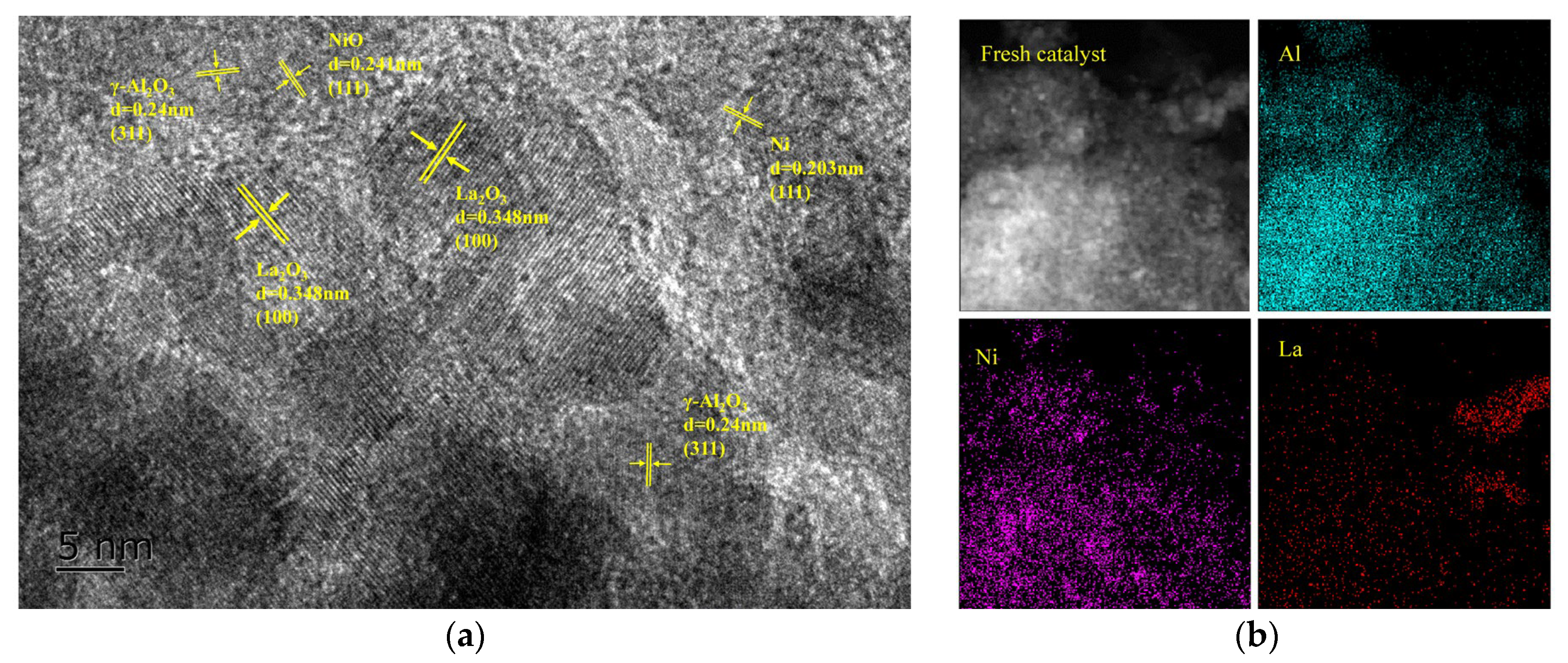
Figure 1. (a) HRTEM image and (b) EDX elemental maps for the fresh La−Ni/γ−Al2O3 catalyst.
Catalysts 13 00686 g001
Figure 2. (a,b) CH4 and CO2 conversion, (d) H2 and CO yield and selectivity and (f) H2/CO of CH4 dry reforming in the absence and presence of tar model compounds, and (c) tar removal rate under N2 and a gas mixture (N2, CO2 and CH4) at different temperatures; (e) CH4, CO2 conversion and H2, CO selectivity of CH4 dry reforming in the presence of tar at 250 °C, 330 °C and 450 °C. (Discharge power: 35 W, N2/CO2/CH4 ratio:2:1:1, total flow rate: 300 mL/min, tar concentration: 29.6 g/m3, catalyst: 2%La−10%Ni/γ−Al2O3.)
Catalysts 13 00686 g002aCatalysts 13 00686 g002b
Figure 3. (a) TGA analyses and (b) Raman spectra of spent catalysts.
Catalysts 13 00686 g003
Figure 4. SEM images of (a) fresh catalyst and the solid carbon deposition on the spent catalysts obtained from the (b) MRT, (c) TRO and (d) MRO processes and (eh) carbon fibres blocking the channels on the catalyst surface; (i) TEM image, (j) HAADF image and (k) EDX elemental map for Ni in the spent catalyst under TRO process and (l,m) HRTEM images of the spent catalyst from MRO. (Benzene content: 29.6 g/Nm3, discharge power: 35 W, reaction time: 2 h, temperature: 450 °C.)
Catalysts 13 00686 g004
Figure 5. Reaction mechanism of the catalytic process.
Catalysts 13 00686 g005
Figure 6. Proposed reaction mechanism for benzene reforming under (a) a pure N2 atmosphere and (b) a gas mixture (N2, CH4 and CO2) atmosphere over a La−Ni/γ−Al2O3 catalyst in the DBD plasma reactor.
Catalysts 13 00686 g006
Disclaimer/Publisher’s Note: The statements, opinions and data contained in all publications are solely those of the individual author(s) and contributor(s) and not of MDPI and/or the editor(s). MDPI and/or the editor(s) disclaim responsibility for any injury to people or property resulting from any ideas, methods, instructions or products referred to in the content.