Article

Synthesis and Analysis of In2CdO4/Y2SmSbO7 Nanocomposite for the Photocatalytic Degradation of Rhodamine B within Dye Wastewater under Visible Light Irradiation

1
School of Physics, Changchun Normal University, Changchun 130032, China
2
State Key Laboratory of Pollution Control and Resource Reuse, School of the Environment, Nanjing University, Nanjing 210093, China
*
Authors to whom correspondence should be addressed.
Catalysts 2023, 13(3), 608; https://doi.org/10.3390/catal13030608
Submission received: 1 July 2022 / Revised: 10 March 2023 / Accepted: 13 March 2023 / Published: 17 March 2023

Abstract

:
A new photocatalyst In2CdO4 was prepared by a solid phase sintering synthesis method at high temperature for the first time in this paper. The In2CdO4/Y2SmSbO7 heterojunction (IYH) catalyst was prepared by the solvent thermal method for the first time. The Y2SmSbO7 compound crystallized in the pyrochlore-type architecture and cubelike crystal system, and the space group of Y2SmSbO7 was Fd3m and the crystal cell parameters of Y2SmSbO7 was 9.51349 Å. The band gap width of Y2SmSbO7 was 2.63 eV. In2CdO4 crystallized with a body centered tetragonal lattice structure which was a tetragonal crystal system with a space group of I41/amd. The band gap width of In2CdO4 was 2.70 eV. After 110 minutes of visible light irradiation (VLGI-110min) with IYH as the photocatalyst, the removal rate (RR) of rhodamine B (RhB) concentration was 100% and the total organic carbon (TOC) concentration RR was 99.71%. The power mechanics invariable k toward RhB consistency and visible light irradiation (VLGI) time with IYH as the photocatalyzer reached 0.03073 min−1. The power mechanics invariable k which was involved with TOC reached 0.03621 min−1. After VLGI-110min, the RR of RhB with IYH as the photocatalyzer was 1.094, 1.174 or 1.740 times higher than that with In2CdO4, Y2SmSbO7 or N-doping TiO2 (N-TO) as the photocatalyzer, respectively. The results showed that the photocatalytic activity of IYH was the highest compared with In2CdO4, Y2SmSbO7, or N-TO. With appending a trapping agent, the oxidative capability for degrading RhB, which ranged from strong to weak among three oxidative radical groups, was as follows: hydroxyl radicals > superoxide anion > holes. This work provided a scientific basis for the research which resulted in prosperous development of efficient heterojunction compound catalysts.

1. Introduction

Industrial sewage from fabric and yarn dyeing was one of the major environmental polluters and could not be efficaciously eliminated after the conventional treatments. During the past decades, global concerns about the discharged wastewater from textile industries which usually contained a large amount of various dyes, had been intensified. Dyes and pigments were widely used in various industries such as the textile, leather, ceramic, cosmetic and food processing industries. The majority of these dyes were chemically stable, less adapted to biological treatment and were toxic to the environment due to their resistance to aerobic degradation and formation of carcinogenic aromatic amines during anaerobic degradation. Therefore, decomposition and removal of these pollutants from wastewater were necessary steps before the wastewater was discharged into aquatic ecosystems [1]. However, most textile dyes were photolytically stable and refractory towards chemical oxidation [2,3] and these characteristics rendered them resistant towards decomposition by conventional biochemical and physicochemical methods, such as adsorption on activated carbon, coagulation by a chemical agent or reverse osmosis which was applied to such effluents [4,5]. Rhodamine B (RhB), one of the most common xanthene dyes, has been universally used in many commercial manufacture processes and biotechnology applications, for instance in paper dyeing, dye laser production, fluorescence microscopy, flow cytometry and ELISA [6,7]. However, in recent years, RhB was not permitted to be used in foods and toiletries because it had been found to be potentially toxic and carcinogenic [8,9]. Therefore, an efficient method for degrading RhB needed to be urgently proposed. Chemical oxidation processes such as ozonation was effective for the decolorization of organic dyes. However, the use of such oxidants was limited due to the formation of possibly toxic non-degradable by-products. Therefore, beside the decolorization of polluted water, it was important to mineralize the by-products which could be generated during the treatment process because some of those by-products might be more toxic and carcinogenic than the initial pollutant. Hence, it was necessary that the mineralization rate of toxic organic pollutants in wastewater ought to reach the maximum standard for preventing the untreated wastewater from being discharged into aquatic ecosystems [1].
Recently, in order to overcome these limitations and to meet the need for environmentally friendly methods that would not produce residual toxic by-products, advanced oxidation processes (AOPs) have been widely considered. AOPs were recognized as a powerful and effective method for the degradation and mineralization of a wide range of recalcitrant organic contaminants which could not be eliminated by conventional treatment techniques in wastewater. These methods involved the in situ generation of active, unstable and non-selective oxidizing species like hydroxyl radicals (•OH) that could oxidize most of the durable organic contaminants in polluted water [1]. Among the rest, photodegradation by a photocatalyst was considered to be a promising technology because of the low cost and high environmental benefits. Photocatalysis was well reported in the literature for organic pollutant degradation in water environments under visible light irradiation and UV light irradiation. Aziz et al. (2019) used a photocatalytic down membrane reactor to study the degradation pathway of the pharmaceutical drugs diclofenac and ibuprofen in aqueous solution. The experimental results showed that the low mineralization rate of both drugs went through photocatalytic reactions with low-chain carboxylic acids such as formic acid, acetic acid, oxalic acid, acetic acid, malic acid and succinate which were regarded as the main by-products. Thus, the degradation pathways of diclofenac and ibuprofen were proposed [10]. In our work, we also found that the organic dyes such as RhB in the wastewater could also be effectively degraded by the use of a photocatalyst.
Light-activated semiconductor-based photocatalysis represents the most promising green and eco-friendly technique for wastewater treatment [11,12]. It has received a lot of attention due to its high efficiency, low-cost and outstanding stability [10]. Electrons (e) and holes (h+) which migrated to the surface of the photocatalyst [13,14,15,16,17,18] were generated under light irradiation. As a result, redox reactions were induced and the reactive free radical groups such as superoxide radical (O2−), singlet oxygen (1O2), hydroxyl radical (OH•), hydroperoxyl radical (HOO•) and hydroperoxide (H2O2) were formed.
Reactive oxygen species with high oxidative and reductive activity could easily degrade organic pollutant molecules and inorganic pollutant molecules. Although many significant advances have been made in photocatalysis, two major bottlenecks have limited the practical applications of pristine photocatalysts under solar light. First, several pure photocatalysts with wide band gaps could only be activated using ultraviolet light [19,20,21,22,23,24,25], which accounts for less than 5% of the sunlight spectrum. Second, photoproduced e and photoproduced h+ pairs which derived from a single semiconductor photocatalyst were generally easily recombined and, as a result, the light quantum efficiencies and the photocatalytic efficiencies were reduced [25,26,27,28]. For the purpose of improving the catalytic activity of the photocatalysts, element doping [29,30,31,32,33], semiconductor coupling, and dye sensitization [33,34,35,36,37] were investigated. Semiconductor coupling is one of the most popular research hotspots for photocatalysis since it allowed for the introduction of heterojunction systems which could effectively improve the separation of e and h+ [38,39,40,41,42,43,44].
In a previously published report, graphitic carbon nitride (g-C3N4), an organic layered with a two-dimensional metal-free catalyst, is constituted by a π-conjugated system. As a metal-free photocatalyst, the narrow bandgap energy (Eg) of g-C3N4 (~2.7 eV) resulted in a strong response to the visible light wavelength of 460 nm. However, low photocatalytic efficiency occurred in the single-phase g-C3N4 because of its high recombination rate of electron–hole (e-h+) pairs, lack of surface redox-active sites, and disordered structure/defects. Therefor Saravanakumar et al. (2021) have rationally obtained a new ternary-symmetrical dual-z-type LaFeO3/g-C3N4/BiFeO3 (LCB) heterojunction nanometer composite by using a wet chemical process. This double Z-scheme photocatalyst showed outstanding photocatalytic performance for ciprofloxacin (CIP) degradation compared to g-C3N4, LaFeO3, BiFeO3 and their binary nanocomposites. The enhanced photocatalytic activities were primarily derived from the improved of light absorption capability, effective spatial separation and prolonged charge carrier lifetime in the double Z-scheme system. In particular, the scavenger tests and electron spin resonance spectra demonstrated that •O2− and •OH are the primary oxidative radical species in the photocatalytic systems and confirmed the formation of the double Z-scheme structure. This study may provide new insights into the design and synthesis of highly efficient double Z-scheme photocatalysts for environmental decontamination [45]. Additionally, Saravanakumar et al. (2018) previously reported a novel visible-light-driven Ag/CdO photocatalyst, fabricated for the first time via a one-pot hydrothermal method and further applied for the photodegradation of two important exemplar water contaminants, malachite green and acid orange 7. In their experimental work, they found that (5%) of the Ag/CdO nanocomposites showed strong photocatalytic activity and pointed out this result was attributed to the synergistic effect between Ag and CdO. Ag NPs mainly acted as an electron trap site, which could reduce the recombination of the electron-hole and induce visible light absorption. The preparation of heterojunction has also been an effective strategy because it can increase the photo-responsive range and improve the charge separation efficiency of the photocatalyst [46].
According to the previous reports, serial A2B2O7 compounds could be better photocatalysts [39,40,41,42,43]. For example, some scientists have prepared Bi2MNbO7 (M = Al3+, In3+, Fe3+, Sm3+) via the sol–gel route, and the results showed that the Bi2FeNbO7 compound family possesses momentous light catalyst activity. The Bi2FeNbO7 prepared using the sol–gel (400 °C) reaction accelerator had high light catalyst activity in the degradation of methylene blue in dye wastewater [44].
In this article, a series of experiments with In2CdO4/Y2SmSbO7 heterojunction (IYH) as the photocatalyst for the degradation of RhB were designed for the first time. IYH was compared to the previously reported composites for the degradation of RhB which is an emblematic organic pollutant. Wang et al. found that the degradation of RhB in aqueous solution by swirling jet-induced cavitation combined with H2O2 was investigated. It was found that there was an obvious synergetic effect between hydrodynamic cavitation and H2O2 for the degradation of RhB, while it was found that the degradation of RhB was strongly dependent on the medium’s pH value. The removal of RhB increased with the decrease in medium pH value. When the pH was 10.0, the residual concentration of RhB was 3.56 mg L−1 and the removal ratio was only 64.4% after 180 min treatment. However, the residual concentration was 0.08 mg L−1 or 0.11 mg L−1 at a pH value of 2.0 or 3.0, respectively. It could be found that swirling jet-induced cavitation combined with H2O2 showed the highest RhB degradation rate [44,45,46,47,48,49,50]. However, although this improved the degradation rate of RhB, the results were not ideal. Therefore, the new photocatalyst which was studied in this paper possesses higher degradation efficiency in the degradation process of RhB, which made our work more meaningful, reflecting the advantages of the new photocatalyst IYH.
In this investigation, our aim was to prepare a new type of heterogenous junction (HJ) photocatalyst which could remove RhB from dye wastewater under VLGI. The innovative aspect of our work was that a new type of Y2SmSbO7 catalyst and IYH photocatalyst were synthesized by a high-temperature, solid-phase sintering synthesis method for the first time. Additionally, we obtained Y2SmSbO7 or IYH that was a visible-light-responsive photocatalyst with higher photocatalytic activity for effectively removing RhB. The removal of organic pollutants from dye wastewater using IYH photocatalyst was more efficient and safer.

2. Result and Discussion

2.1. X-Ray Diffractometer (XRD) Analysis

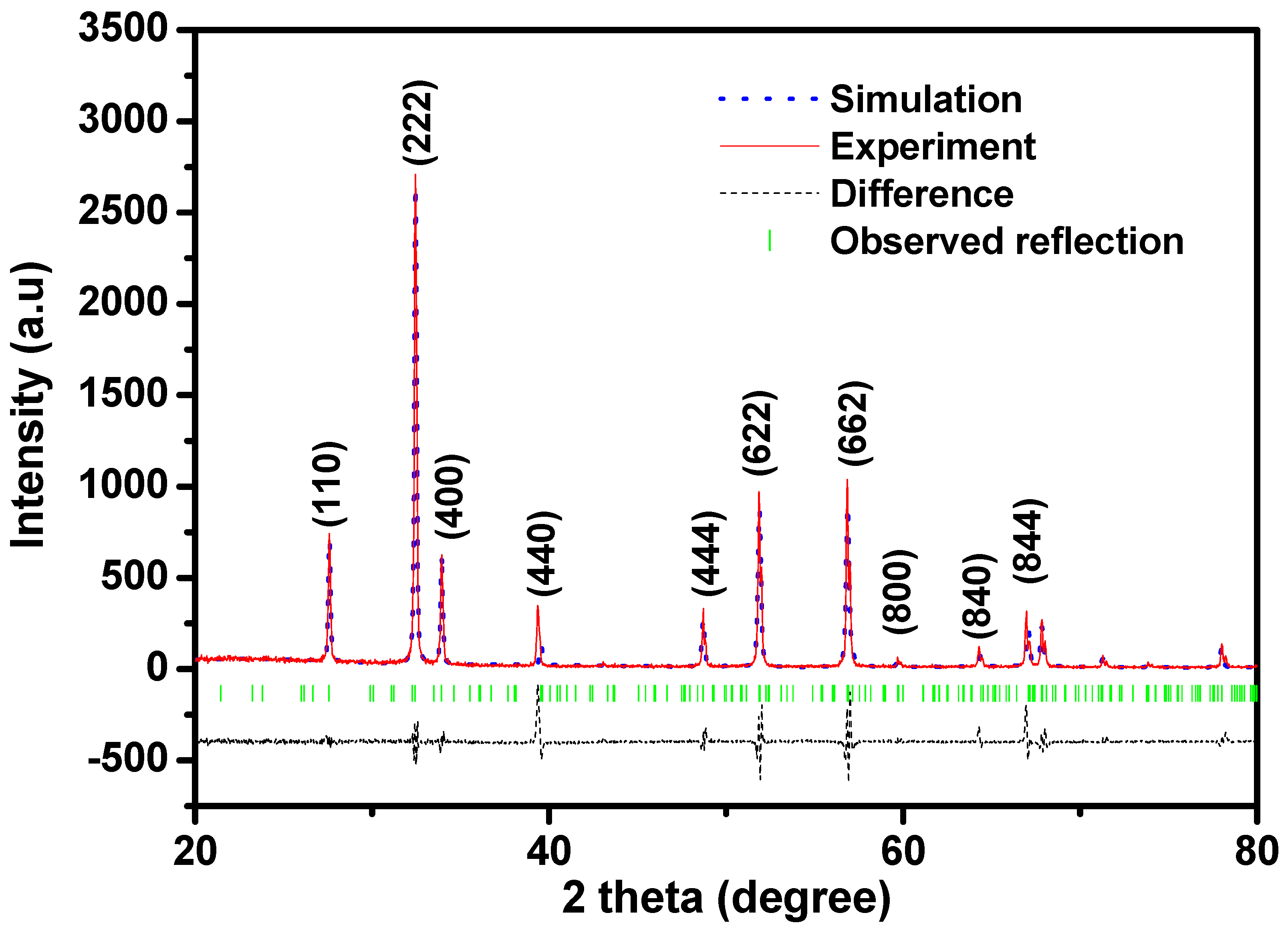
Figure 1 shows the X-Ray powder diffraction (XRD) pattern of Y2SmSbO7. The Materials Studio software was applied to obtain the quantitative data based on Rietveld analysis. The results showed that Y2SmSbO7 was a single phase and the lattice parameters of the new type of photocatalyst Y2SmSbO7 was 9.51349 Å. At the same time, the ultimate refinement result for Y2SmSbO7 showed that there was a good consistency between the observed strength and the surveyed strength of the pyrrhite structure, which was a cubelike crystal system with a interspace group of Fd3m (O atoms were included in the mold). Moreover, the total indices of the crystallographic plane for Y2SmSbO7 could be successfully indexed according to the Rietveld analysis results which were derived from the XRD pattern of Y2SmSbO7. Table 1 shows the atom co-ordinates and architecture parameters of Y2SmSbO7. We can conclude from Figure 1 that Y2SmSbO7 crystallized into a pyrochlore-type structure which possessed a crystal system and space group of Fd3m. Based on the results of the Rietveld refinement, the RP =15.30% with space group Fd3m was obtained for Y2SmSbO7.
It should be noted that the x co-ordinate of the O (1) atom could be regarded as an index of the change of the transistorization architecture by the pyrochlore-type A2B2O7 compounds (cubic, space group Fd3m) and was equivalent to 0.375 when the six A-O (1) bond distances were equal to that of the two A-O (2) bond distances [51]. Therefore, information about the deformation of the MO6 (M = Fe3+ and Sb5+) octahedra could be obtained from the x value [49]. The x value was shifted by x = 0.375 [49], and therefore the deformation of the MO6 (M = Fe3+ and Sb5+) octahedra was visible in the crystalloid architecture of Y2SmSbO7. Electric charge disassociation was demanded for photocatalytic degradation (PCD) of RhB under VLGI to avert regroupment of the photo-induced electrons and photo-induced cavities. Inoue [52] and Kudo [53] had shown that the partial deformation of the MO6 octahedra which was gained from several photocatalyzers, for instance, BaTi4O9 and Sr2M207 (M = Nb5+ and Ta5+), was very important for averting the electric charge regroupment and contributed to increased photocatalytic activity. Therefore, the distortion of the MO6 (M = Fe3+ and Sb5+) octahedra in the crystal structure of Y2SmSbO7 may also enhance the photocatalytic activity. Y2SmSbO7 included a three-dimensional (3D) meshwork architecture of corner-sharing MO6 (M = Fe3+ and Sb5+) octahedra. The MO6 (M = Fe3+ and Sb5+) octahedra were connected into catena by Y3+ ions. Two kinds of Y-O bond distances coexisted: the six Y-O (1) bond distances of 2.614 Å were visibly longer than that of the two Y-O (2) bond distances of 2.183 Å. The six M-O (1) (M = Sm3+ and Sb5+) bond distances were 1.97635 Å and the M-O (2) bond distances were 4.459 Å. The M-O-M (M = Sm3+ and Sb5+) bond angles (BDA) were 138.732° in the crystal structure of Y2SmSbO7. The Y-M-Y (M = Sm3+ and Sb5+) BDA were 134.500° in the crystal structure of Y2SmSbO7. The Y-M-O (M = Sm3+ and Sb5+) BDA were 134.803° in the crystal structure of Y2SmSbO7. The research on its luminescence characteristics showed that the closer the M-O-M bond angle was to 180°, the more the excitation state was nonlocalized [51]. It revealed that the angles between the corner sharing MO6 (M = Sm3+ and Sb5+) octahedra, for instance, the M-O-M BDA for Y2SmSbO7 was significant for affecting the photocatalyst activity of Y2SmSbO7. If the M-O-M BDA was close to 180 degrees, the mobility of the photo-induced electrons and photo-induced cavities would be large [51]. The mobilities of the photo-induced electrons and photo-induced holes affected the probability of electrons and cavities to reach reaction sites on the catalyzer skin layer which, in the end, led to the influence on the photocatalytic activity [51].
In addition, the Sb–O–Sb bond angle of Y2SmSbO7 was larger, and thus, the photocatalytic activity of the Y2SmSbO7 catalyst was improved. As to Y2SmSbO7, Y is a 4p-block rare-earth (RE) metallic element, Sm is a 4f-block metallic element, and Sb is a 5p-block metallic element. Based on above analysis, the impact of retrograding RhB under VLGI with Y2SmSbO7 as the photocatalyst could be chiefly credited to its crystal structure and electronic structure.
Figure 2 shows the XRD pattern of In2CdO4. The Materials Studio software was used to obtain the quantitative data based on the Rietveld analysis. The results (Figure 2) showed that In2CdO4 was a single phase and the lattice parameters of the new type of photocatalyst In2CdO4 was a = 14.9443 nm, b = 14.9443 nm, c = 9.9394 nm, α = 90°, β = 90°, and γ = 90°. At the same time, the ultimate refinement result for In2CdO4 showed that there was a good consistency between the observed strength and the surveyed strength of the body-centered tetragonal lattice structure, which was a tetragonal crystal system with a space group of I41/amd (O atoms are included in the mold). Moreover, the total indices of the crystallographic plane for In2CdO4 could be successfully indexed according to the Rietveld analysis results which were derived from the XRD pattern of In2CdO4. We can conclude from Figure 2 that In2CdO4 crystallized into body-centered tetragonal structure which possessed a tetragonal crystal system and space group of I41/amd. Based on the results of the Rietveld refinement, a RP = 15.30% with space group I41/amd was obtained for In2CdO4. Other impurities was not detected in Figure 2.
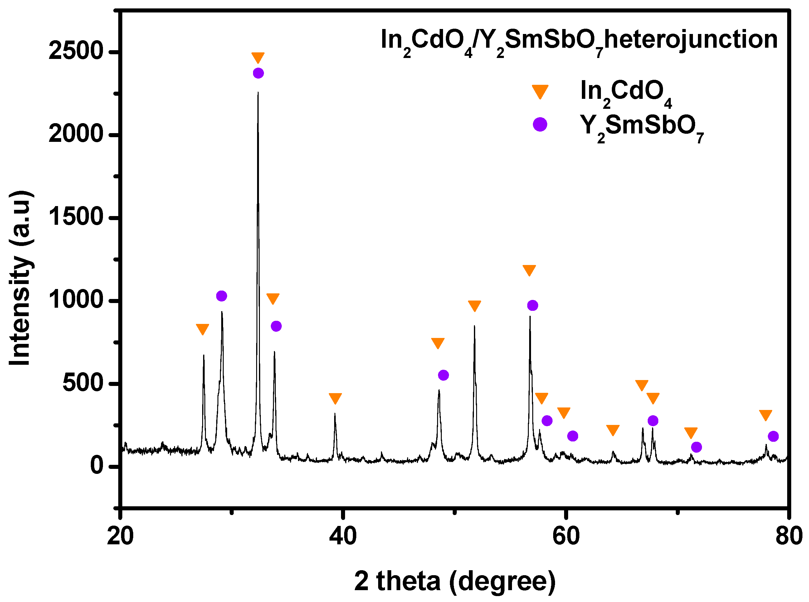
Figure 3 shows the XRD diffraction pattern of the In2CdO4/Y2SmSbO7 HJ photocatalyzer. From Figure 3, the presence of the pure single crystal photocatalyzer In2CdO4 and single-phase photocatalyzer Y2SmSbO7 could be seen. The indices of crystallographic plane of every diffraction peak of In2CdO4 and every diffraction peak of Y2SmSbO7 was resoundingly labeled and the impurities were not detected in Figure 3. Figure 3 also showed that the XRD image of the In2CdO4/Y2SmSbO7 HJ had a single phase with perfect crystallinity and the defects were not found inside the crystal. Thus, the photo-induced electrons and the photo-induced holes which were generated during the photocatalytic reaction, did not aggregate and compound at the defects inside the crystal catalyst. Thereby we should prolong the service life of the photo-induced electrons and photo-induced cavities and improve the catalytic activity of the photocatalyst.

2.2. UV-Vis Diffuse Reflectance Spectra

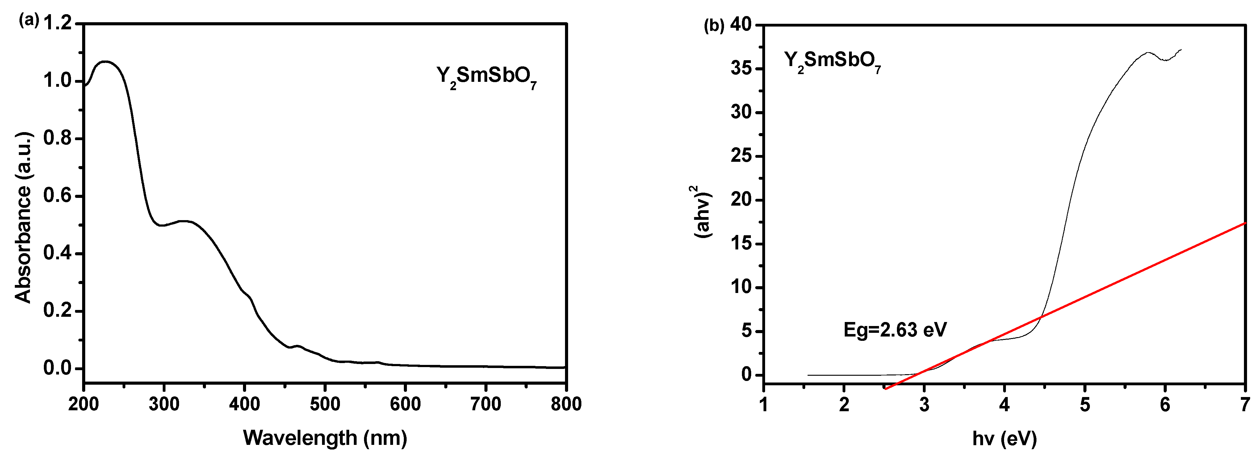
The absorption spectrum of the Y2SmSbO7 sample is shown listed in Figure 4a,b. The absorption edge of this new photocatalyst Y2SmSbO7 was discovered to be at 458 nm which was in the visible range of the optical spectrum. The band-gap energy (B-GE) of the crystalline semi-conductors could be calculated using the point of crossing between the photon energy axis and the line calculated from the linear section of the absorption edge of the so-called Kubelka–Munk function (1) (called re-emission function) [54,55].
[ 1 R d ( h ν ) ] 2 2 R d ( h ν ) = α ( h ν ) S
where S is the dispersion factor, R d is the spread reflection, and α is the delegated absorbability modulus of radialization.
The optic absorbability near the energy band edge of a crystalline semiconductor conforms to Equation (2) [56,57]:
A h ν = A ( h ν E g ) n
Here, A, α , E g , and ν represent the ratable numeric constant, absorbability modulus, band gap, and light frequency, respectively. In this equation, n determines the properties of the transitions in the semiconductors. E g and n could be determined using the lower row process: (1) draw ln ( α h ν ) versus ln ( h ν E g ) assuming an approximate value of E g ; (2) infer the value of n based on the rate of grade in the Figure; (3) draw ( α h ν ) 1 n and h ν to refine the value of E g and extrapolating the graph to ( α h ν ) 1 n =0. According to the above method, the E g value of Y2SmSbO7 was calculated to be 2.63 eV. The estimated value of n was about 2 and indirectly allowed the optical transition of Y2SmSbO7. Figure 5a,b shows the UV-Vis diffuse reflectance spectrum of In2CdO4. In light of above the sequences and Figure 5a,b, the value of E g for In2CdO4 was calculated to be 2.70 eV. The estimated value of n was about 0.5, which directly allowed the optical lambda transition of In2CdO4.
The absorption spectra of the IYH specimen are ranked in Figure 6a,b. The B-GE of Y2SmSbO7 was 2.63 eV, the B-GE of In2CdO4 was 2.70 eV, the B-GE of IYH was 2.28 eV [58], and the B-GE of co-doping ZnO was 2.39 eV [59]. All the B-GE of these three chemical compounds (CMPDs) were less than 2.87 eV, which implied that these three catalyzer possessed visible light response properties and held blastissimo latent energy for displaying high photocatalyst activity under VLGI.

2.3. Property Characterization of In2CdO4/Y2SmSbO7 Heterojunction Photocatalyst

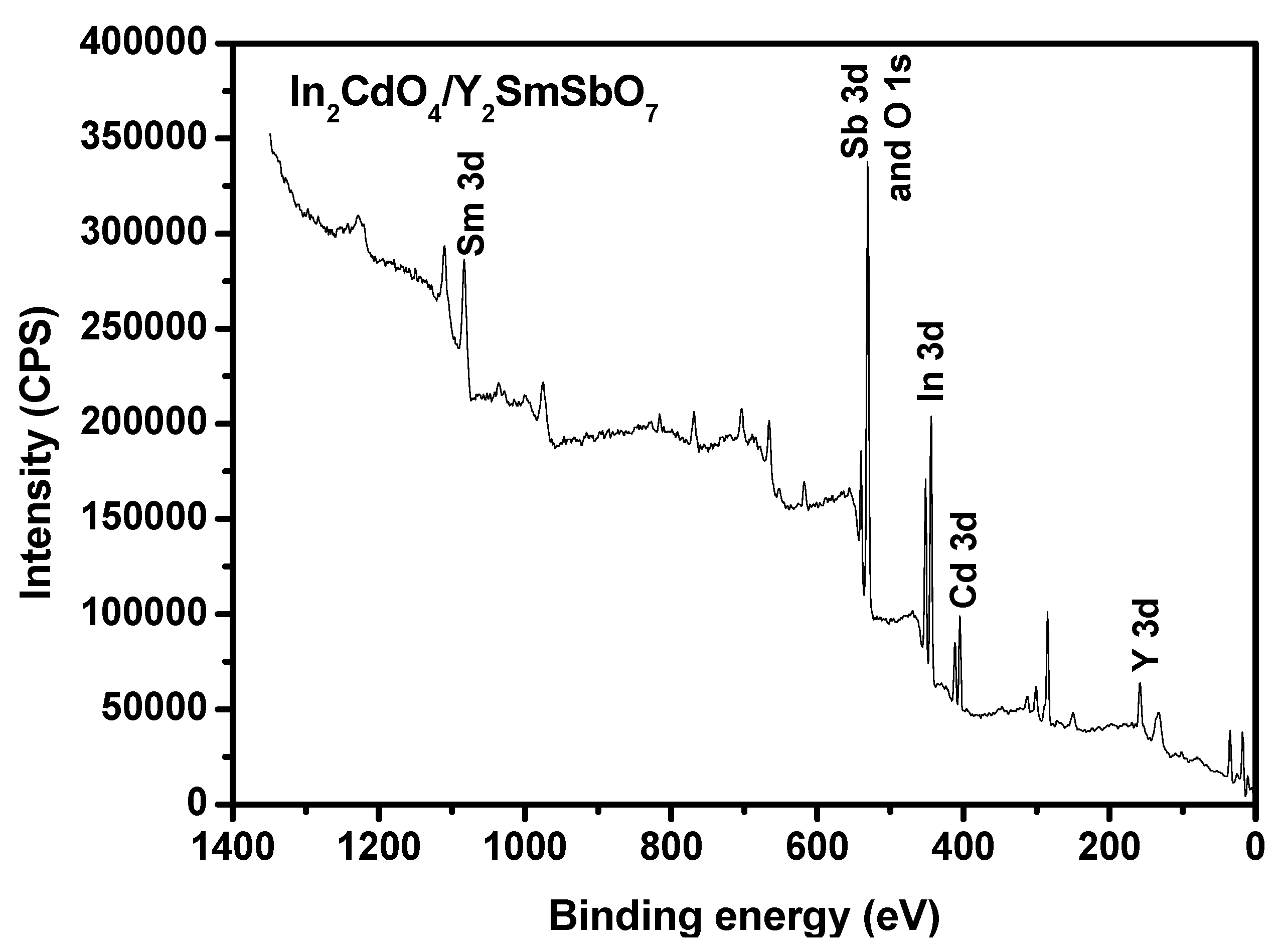
To obtain the skin layer chemical constitution and the quantivalency ungerade states u of each constituent of IYHP, the X-ray photoelectron spectrum (XPS) was measured. Figure 7 shows the XPS investigation spectra of IYHP. Figure 8 shows the XPS spectra of O2−, In3+, Cd2+, Y3+, Sm3+ and Sb5+ which were derived from IYHP. In light of the XPS full spectrum which is shown in Figure 7, the synthesized IYHP included the elements of O, In and Gd. In light of the XPS analysis effects which are exhibited in Figure 7 and Figure 8, the oxidation state of O, In, and Cd ion was −2, +3 and +2, respectively. Due to the analysis results, it could be summarized that the chemical formula of the new CMPD was In2CdO4/Y2SmSbO7. It could be seen from Figure 8 that multifarious elemental apices with unique binding energies were obtained. In Figure 8, the O1s peak of O was situated at 529.90 eV. The In3d3/2 and In3d5/2 peak of In was situated at 451.70 eV and 445.40 eV, respectively. The Cd3d5/2 peak of Cd was situated at 411.50 eV. Thus, Figure 7 and Figure 8 exposed the existence of indium (In3d3/2 and In3d5/2), cadmium (Cd3d5/2), and oxygen (O1s) within the prepared specimen. The skin layer elemental analysis results showed that the media atomic rate of In:Cd:O was 198:99:397. The atomic ratio of In:Cd:O and Y:Sm:Sb:O in the IYHP sample was 1.97:1.00:3.96 and 1.98:0.99:1.00:6.95, respectively.
Obviously, neither shoulders nor widening in the XPS apices of IYHP were observed, which meant that the as-prepared compound for IYHP was pure phase.
Figure S1 displays the XPS survey spectrum of the In2CdO4. As illustrated in Figure S1, the full XPS spectrum of In2CdO4 revealed that the synthesized In2CdO4 consisted of the elements of In, O and Cd. As to In2CdO4, the oxidation state of In, Cd or O ion was +3, +2 or −2. The C element came from hydrocarbons used in the testing.
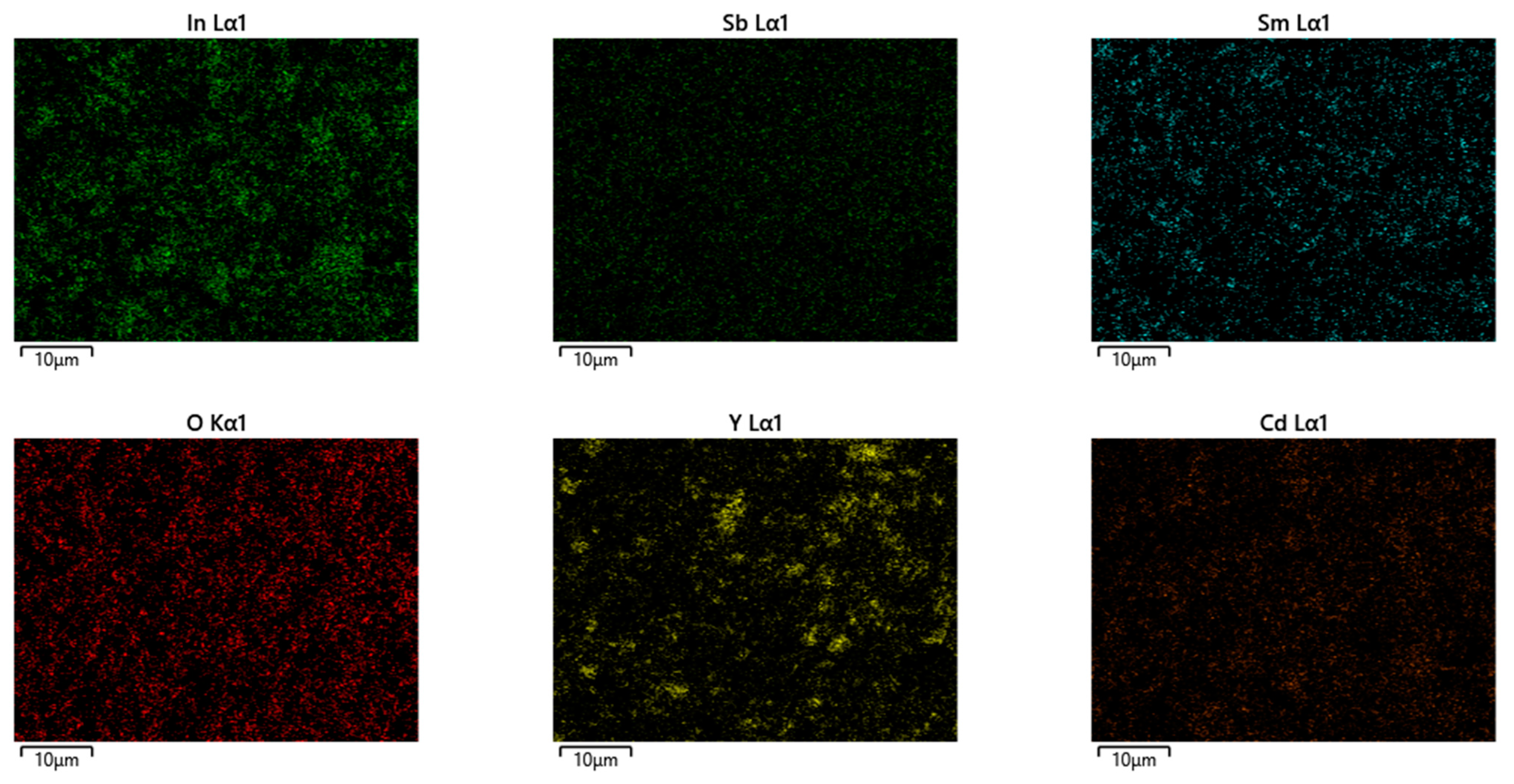
Figure 9 shows the TEM image of In2CdO4 and the selected area’s electron diffraction pattern of In2CdO4. It could be found from Figure 9 that the mean particle size was 297 nm for In2CdO4. Figure 9 clearly shows that In2CdO4 crystallized with a body-centered tetragonal lattice structure which possessed a tetragonal crystal system and space group of I4/amd, and the lattice parameters for In2CdO4 were proved to be a = 14.9443 nm, b = 14.9443 nm, and c = 9.9394 nm. According to the calculation results from Figure 9, the main diffraction peaks which were the same as those which were derived from Figure 2 for In2CdO4 could be found. Figure 10 shows the TEM image of In2CdO4/Y2SmSbO7. Figure 11 shows the EDS elemental mapping of IYHP (In, Cd, O from In2CdO4 and Y, Sm, Sb, O from Y2SmSbO7). It could be predicated from Figure 11 that IYHP contained indium, cadmium, yttrium, samarium, stibonium, and oxygen.
Figure S2 shows the SEM photograph of In2CdO4. The SEM-EDS analysis results which are shown in Figure S2 revealed that there were no other elements in the In2CdO4. Figure S3 shows the EDS elemental mapping of In2CdO4. In2CdO4 contained indium, cadmium, and oxygen.
Figure S4 shows the EDS elemental mapping of Y2SmSbO7. Y2SmSbO7 contained yttrium, samarium, stibonium, and oxygen.
Figure S5 shows the SEM photograph of N-doped TiO2. The SEM-EDS analysis results which are shown in Figure S5 revealed that there were no other elements in the N-doped TiO2. Figure S6 shows the EDS elemental mapping of N-doped TiO2. N-doped TiO2 contained nitrogen, titanium, and oxygen.
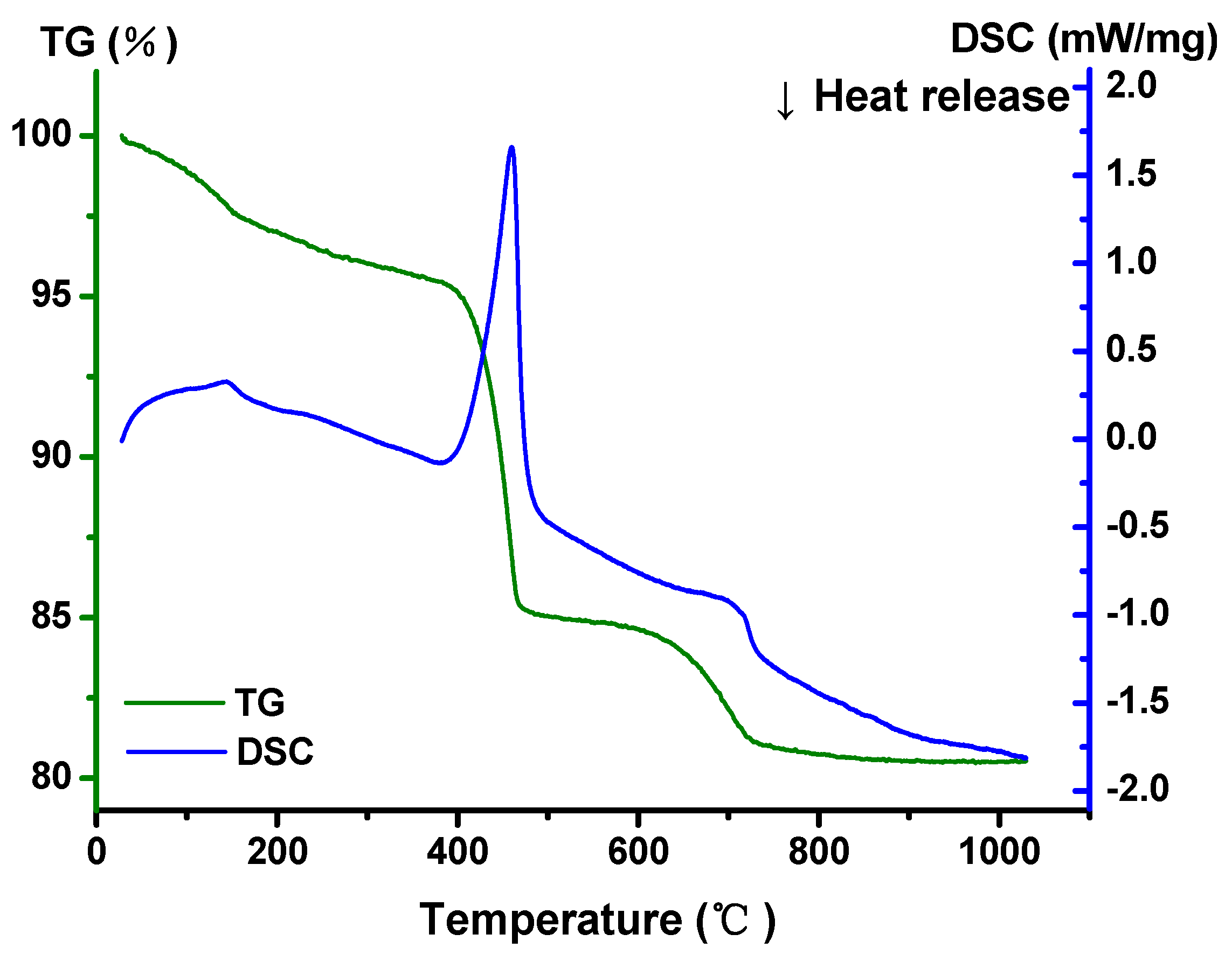
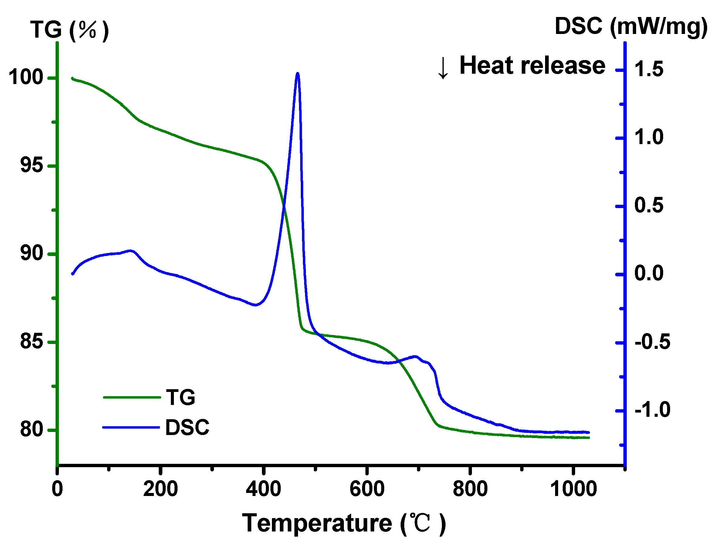
Figure 12 shows the TG-DSC-DTA of Y2SmSbO7. It could be seen from Figure 12 that the thermal weight curve was obviously lost at 440 °C, and there was a significant prominent heat absorption peak, which meant that the high-purity In2O3 and CdO powder materials had an obvious absorption peak at 440 °C because it contained crystalline water. We also found from Figure 13 that there was a prominent endothermic peak at 700 °C, and thus the new phase Y2SmSbO7 was formed at 700 °C. Similarly, it could be seen from Figure 13 that a new phase of In2CdO4 was formed at 720 °C.

2.4. Photocatalytic Activity

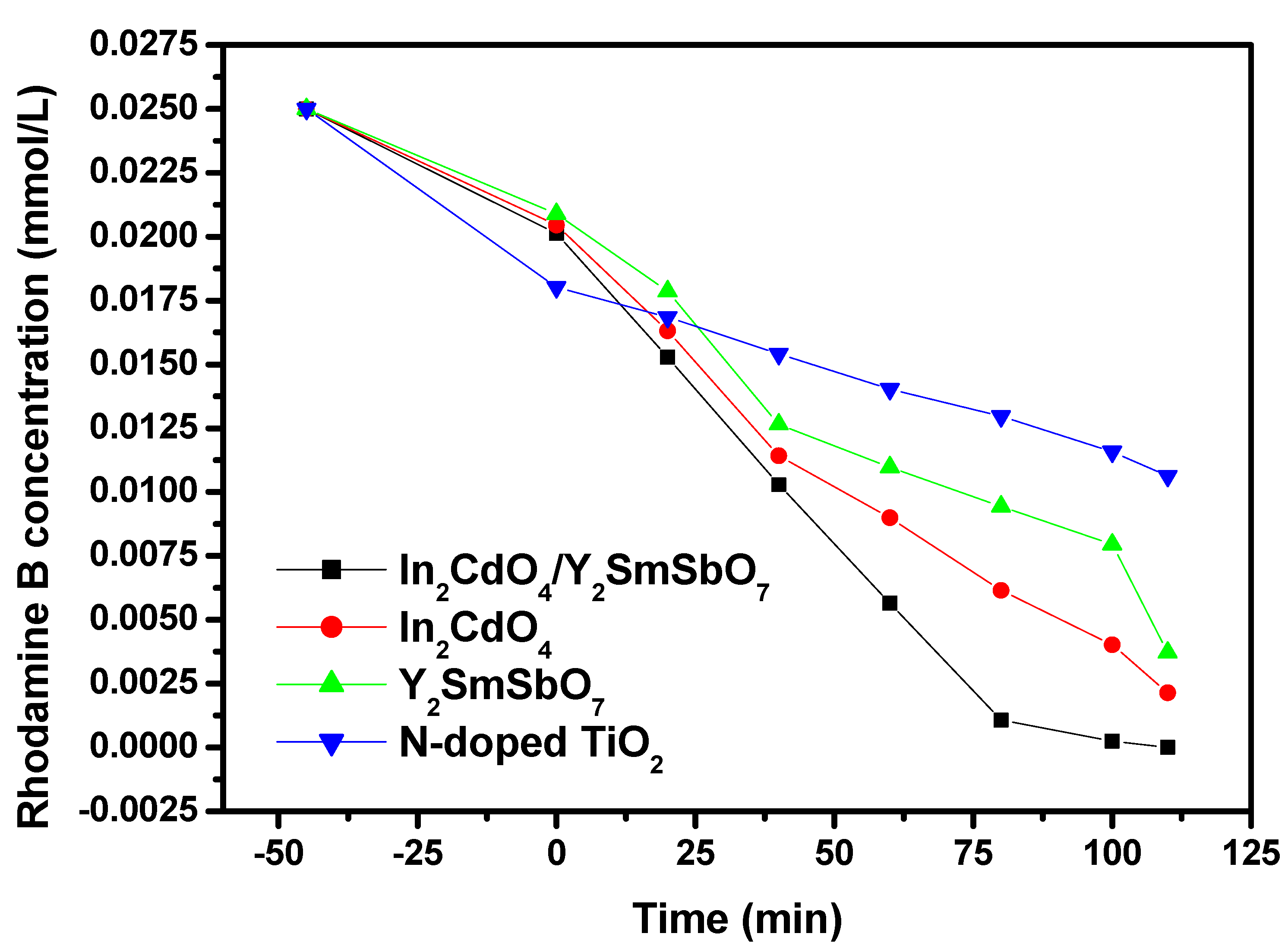
Figure 14 shows the concentration change curve of RhB during the PCD of RhB with IYH, In2CdO4, Y2SmSbO7, or N-TO as the photocatalyzer under VLGI. As could be seen from Figure 14, we first adsorbed RhB in the dark with IYH, In2CdO4, Y2SmSbO7, or N-TO as the photocatalyzer.
As could be seen from Figure 14, when IYH, In2CdO4, Y2SmSbO7, or N-TO was used as the photocatalyst to degrade RhB, the concentration of RhB in the drug wastewater increasingly decreased with increasing VLGI time. The effects shown in Figure 14 indicate that the RR of RhB within the dye wastewater reached 100% and the velocity of the reaction was 3.79 × 10⁻⁹ mol/L/s and the photonic efficiency (PE) was 0.03073% with IYHP as the catalyzer after 110 min of VLGI (VLGI-110min). Additionally, all the other experiments also used 110 min of VLGI. When In2CdO4 was used as the photocatalyst, the RR of RhB reached 91.44% and the rate of reaction was 3.46 × 10⁻⁹ mol/L/s and the PE was 0.0152%. The RR of RhB within the dye wastewater reached 85.16% and the rate of the reaction was 3.23 mol/L/s and the PE was 0.01078% with BiTiSbO6 as photocatalyst. Additionally, the RR of RhB reached 57.48% and the velocity of the reaction was 2.18 × 10⁻⁹ mol/L/s and the PE was 0.00514% with N-TO as the photocatalyst.
Moreover, we could summarize from above effects that the photodegradation efficiency (PGE) of RhB by IYHP was the highest, meanwhile, the PGE of RhB with In2CdO4 as the photocatalyzer was higher than that with Y2SmSbO7 or N-TO, and ultimately, the PGE of RhB with Y2SmSbO7 as the photocatalyzer was higher than that with N-TO, indicating that the visible light photocatalyst activity of IYHP was higher compared to that of In2CdO4, Y2SmSbO7, or N-TO. The above effects showed that the RR of RhB with IYHP was 1.094, 1.174, and 1.740 times higher than that with In2CdO4, Y2SmSbO7, or N-TO as the photocatalyzer after VLGI-110min.
The size of the photocatalyst particle morphology would affect the specific surface area of the photocatalyst. The larger specific surface area of the catalyst, the more active sites on the catalyst surface, and thus the photocatalytic activity would be stronger. When IYH was used as the catalyst, the removal rate of RhB reached 100% after VLGI-110min. The aim of this research work was to develop visible-light-responsive nano materials with low price, high catalytic activity, and full use of the 43% visible light in the solar spectrum. Ultimately, the toxic organic pollutants from pharmaceutical wastewater could be thoroughly purified and removed; meanwhile, a healthier, safer, cleaner, and pollution-free water environment could be obtained.
Figure S7 shows the error bar of the concentration change curves of rhodamine B during PCD of rhodamine B with the In2CdO4/Y2SmSbO7 nanocomposite as the photocatalyzer. Figure S8 shows the error bar of the concentration change curves of rhodamine B during PCD of rhodamine B with the In2CdO4 nanocomposite as the photocatalyzer. Figure S9 shows the error bar of the concentration change curves of rhodamine B during PCD of rhodamine B with the Y2SmSbO7 nanocomposite as the photocatalyzer. Figure S10 shows the error bar of the concentration change curves of rhodamine B during PCD of rhodamine B with the N-doped TiO2 nanocomposite as the photocatalyzer.
Figure 15 shows the concentration change curves of total organic carbon (TOC) during PCD of RhB within dye wastewater with IYH, In2CdO4, Y2SmSbO7, or N-TO as the photocatalyzer under VLGI. The concentration of RhB decreased with increasing VLGI time. As can be seen from Figure 15, the RR of TOC within the dye wastewater reached 99.71%, 87.02%, 82.23%, or 55.3% after VLGI-110min when IYHP, In2CdO4, Y2SmSbO7, or N-TO was used for degrading RhB, respectively. To sum up, the above effects on the RR of TOC during the degradation of RhB using IYHP was higher than that using In2CdO4, Y2SmSbO7, or N-TO. Above results also indicated that the RR of TOC during RhB degradation using In2CdO4 was much higher than that using Y2SmSbO7 or N-TO, which signified that IYHP had the highest mineralization percentage during RhB degradation compared with In2CdO4, Y2SmSbO7, or N-TO.
Figure S11 shows the error bar of the concentration change curves of TOC during PCD of rhodamine B in dye wastewater with the In2CdO4/Y2SmSbO7 nanocomposite as the photocatalyzer. Figure S12 shows the error bar of the concentration change curves of TOC during PCD of rhodamine B in dye wastewater with the In2CdO4 nanomaterial as the photocatalyzer. Figure S13 shows the error bar of the concentration change curves of TOC during PCD of rhodamine B in dye wastewater with the Y2SmSbO7 nanomaterial as the photocatalyzer. Figure S14 shows the error bar of the concentration change curves of TOC during PCD of rhodamine B in dye wastewater with the N-doped TiO2 nanomaterial as the photocatalyzer.
Figure 16 shows the first-order kinetics plots of PCD for RhB under VLGI with IYH, In2CdO4, Y2SmSbO7, or N-TO as the photocatalyzer. As can be seen from Figure 16, the power mechanics invariable k which was obtained from the dynamical line between RhB concentration and VLGI time using IYH, In2CdO4, Y2SmSbO7, or N-TO as the photocatalyzer reached 0.03073, 0.0152, 0.01078, or 0.00514 min−1, respectively. Additionally, the kinetic numeric constant k which came from the dynamic curve of the TOC concentration reached 0.03621, 0.01289, 0.00982, or 0.00465 min−1 with IYH, In2CdO4, Y2SmSbO7, or N-TO as the photocatalyzer. The fact that the value of KTOC for degrading RhB was lower than the value of KC for degrading RhB using the same catalyzer illustrates that the photodegradation intermediates of RhB might appear in the PCD of RhB under VLGI. Meanwhile, in contrast to the other three photocatalysts, IYHP had a higher mineralization workpiece ratio for RhB retrogradation.
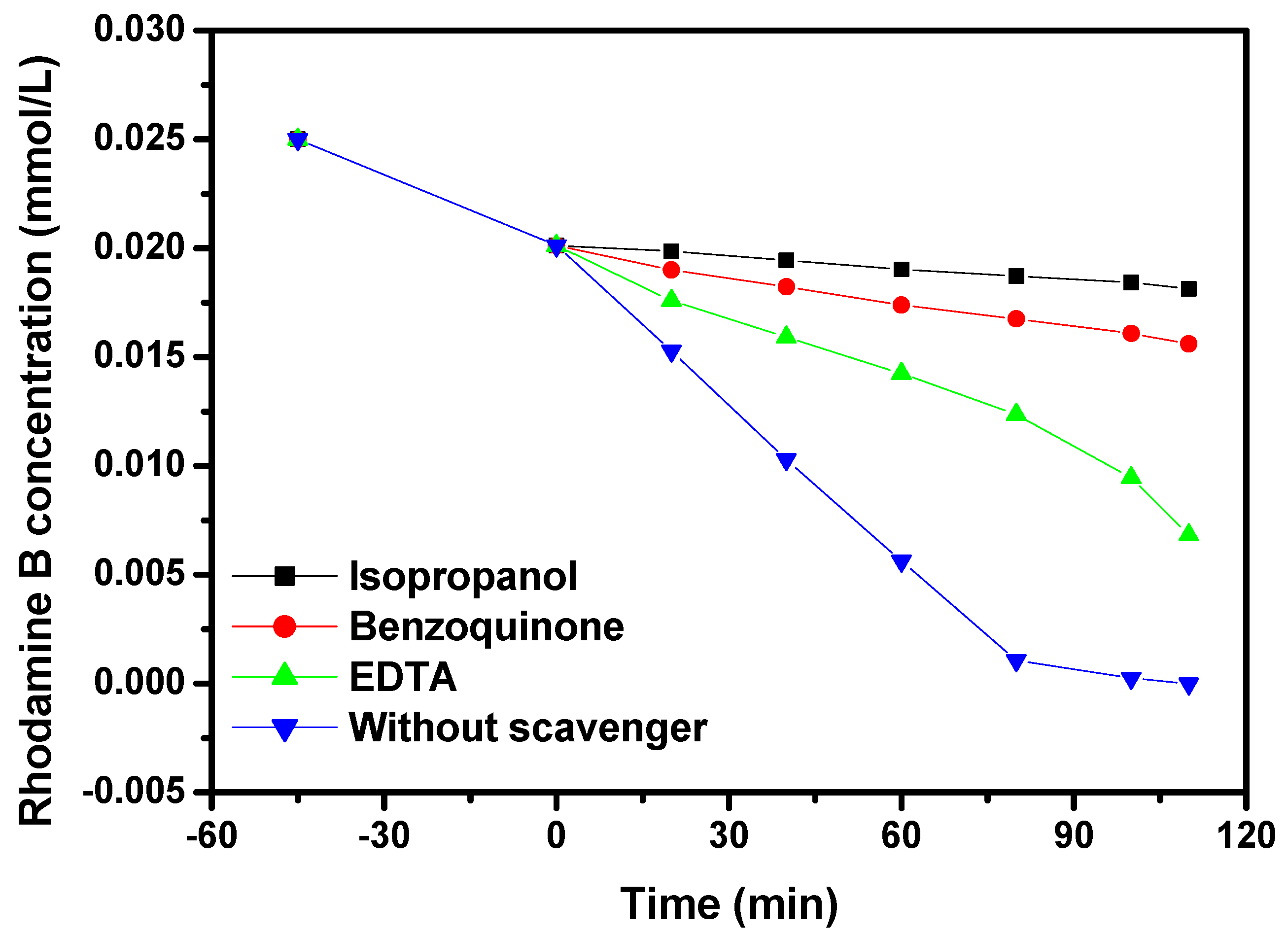
Figure 17 presents the impact of different free radical scavengers (FRSs), for instance, benzoquinone (BQ), isopropanol (IPA), or ethylenediamine tetraacetic acid (EDTA), on the RR of RhB using IYH as the photocatalyzer under VLGI. At the start of the photocatalytic experiment, different FRSs were added to the RhB solution for determining the active species in the retrogradation process of RhB. We used isopropanol (IPA) to capture hydroxyl radicals (•OH); benzoquinone (BQ) was used to capture superoxide anions (•O2); and ethylenediaminetetraacetic acid (EDTA) was used to capture holes (h+). The IPA, BQ, and EDTA concentrations were 0.15 mmol/L, and the added amount of IPA, BQ, and EDTA was 1 mL. As for the selection of free radical scavenger concentration, five concentrations of 0.05 mmol/L, 0.1 mmol/L, 0.15 mmol/L, 0.2 mmol/L, and 0.25 mmol/L of free radical scavengers were used to participate in the reaction. According to the experimental results, the concentration of capture agent was used as the abscissa and [99.16%—C] was used as the ordinate and ultimately, five corresponding curves were obtained. In the term [100%—C], 100% is the removal rate of RhB at 110 min in the blank experiment, and C is the removal rate of RhB after adding the corresponding concentration of capture agent for 110 min. At this time, the curve had a maximum value, which meant that the corresponding radicals were completely captured by the capture agent. At this time, the highest point was determined as the concentration of the free radical scavenger which was required in the experiment.
As shown in Figure 17, when IPA, BQ, or EDTA was added into the RhB solution, the RR of RhB decreased by 72.56%, 62.44%, or 27.28%, respectively, compared with the RR of RhB from the control group. Thus, this demonstrated that •OH, h+, and •O2 were all active free radicals in the process of RhB retrogradation. It could be seen from Figure 11 that •OH in the RhB solution played a leading position when RhB was degraded using IYH as the photocatalyzer under VLGI. In the experiment with the added capture agent, the hydroxyl radical possessed maximal oxidation removal ability for removing RhB within the dye wastewater compared with superoxide anions or holes. The oxidation removal ability for degrading RhB from high to low among the three oxidation radicals was as follows: hydroxyl radical > superoxide anion > holes.
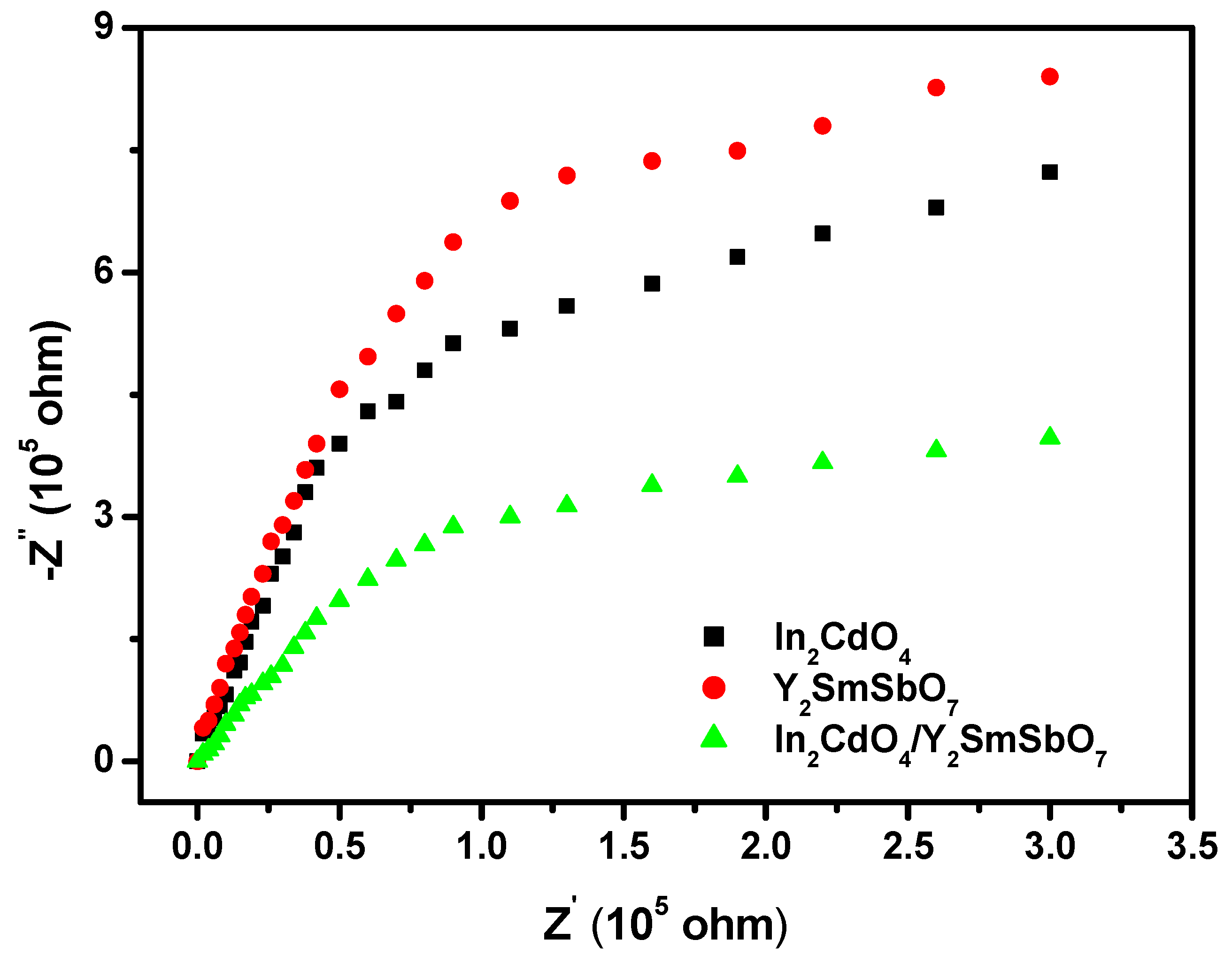
Nyquist impedance plot measurements is another significant qualitative method which showed the photo-induced electron and photo-induced hole transfer process of the prepared photocatalysts at solid/electrolyte interfaces [60,61]. The smaller the arc radius (ARs) was, the higher the transport efficiency of the photocatalyst was. Figure 18 shows the corresponding Nyquist impedance plots of the prepared IYHP, In2CdO4, or Y2SmSbO7 photocatalyzers. In Figure 18 the diameters of the ARs were distinct and were in the order Y2SmSbO7 > In2CdO4 > IYHP. These effects indicated that the prepared IYHP presented a more efficient disassociation of photo-induced electrons and photo-induced holes and faster interfacial charge transfer capability. After 110 min of VLGI, the removal rate of RhB by IYH, In2CdO4, or Y2SmSbO7 was 100%, 91.44%, or 85.16%, respectively, which was also consistent with the results of the curvature radius of the catalysts in the electrochemical impedance experiment. Therefore, it could be concluded that the smaller curvature radius of the catalyst, the higher the removal rate of RhB and catalytic activity of the catalyst.
In addition, with the In2CdO4/Y2SmSbO7 heterojunction as the photocatalyst for degradation of RhB, a series of experiments were designed and compared with the previously reported composites for degradation of RhB in order to reflect the novelty of IYH. Guo et al. studied the synthesis of Fe2O3 nanoparticles which were doped with In2O3. This work aimed to design a kind of photocatalyst based on Fe2O3 nanoparticles which were doped with In2O3 and above nanocomposite was used to degrade RhB. The degradation performance of above prepared catalyst for RhB was explored under different conditions including the doped amount of In2O3, photocatalyst dosage, H2O2 content and pH value. The degradation efficiency reached 94% under optimal conditions [62]. However, although above nanocomposite improved the degradation rate of RhB, the results were not ideal. Therefore, the new catalyst In2CdO4/Y2SmSbO7 heterojunction which was studied in this paper had a higher degradation efficiency during the degradation process of RhB, ultimately, our experimental results made this work more meaningful and reflected the advantages of the new In2CdO4/Y2SmSbO7 heterojunction catalyst.
Table S1 shows the comparison of In2CdO4/Y2SmSbO7 with the other photocatalysts.

2.5. Analysis of Possible Degradation Mechanisms

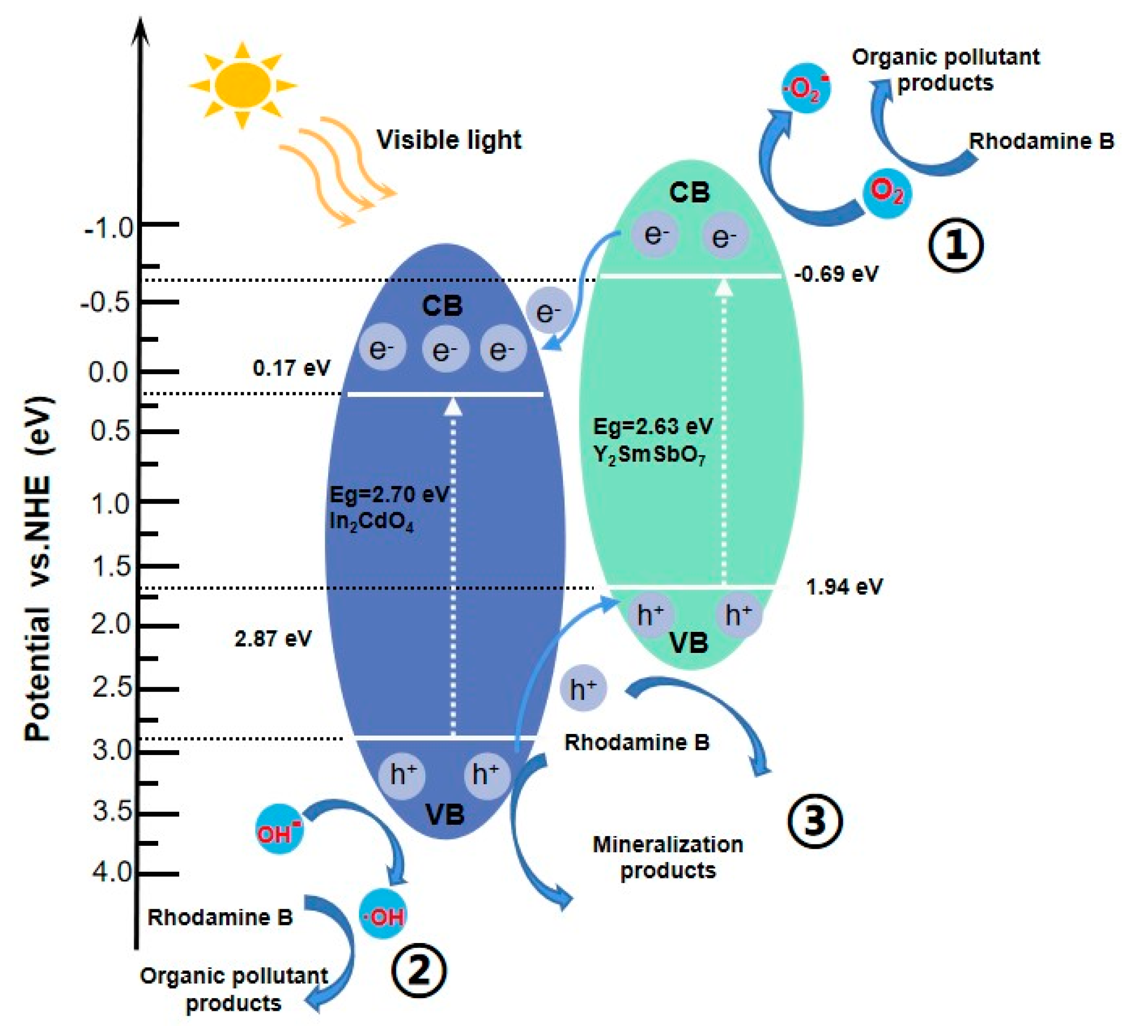
Figure 19 shows the potential PCD mechanism of RhB with the In2CdO4/Y2SmSbO7 nanocomposite as the photocatalyzer under VLI. The potentials of the VB and CB for a semi-conductor catalyzer could be calculated using Formulas (3) and (4) [63]:
ECB = XEe − 0.5Eg
EVB = ECB + Eg
where, Eg is the band gap of the semi-conductor, X is the electronegativity of the semi-conductor, and Ee is the energy of free electrons on the hydrogen scale (about 4.5 eV). According to above formulas, the VB potential or the CB potential for Y2SmSbO7 were estimated to be 1.94 eV or −0.69 eV, respectively. Additionally, for In2CdO4, the VB potential and CB potential were estimated to be 2.87 eV and 0.17 eV, respectively. Both Y2SmSbO7 and In2CdO4 could absorb visible light and internally generated electron–hole pairs when the In2CdO4/Y2SmSbO7 nanocomposite was irradiated with visible light. Owing to the redox potential position of the CB of Y2SmSbO7 (−0.69 eV) being more subtractive than that of In2CdO4 (0.17 eV), the photo-induced electrons on the CB of Y2SmSbO7 could migrate to the CB of In2CdO4. Additionally, the redox potential position of the VB of In2CdO4 (2.87 eV) was more non-negative than that of Y2SmSbO7 (1.94 eV), and therefore the photo-induced holes on the VB of In2CdO4 could migrate to the VB of Y2SmSbO7.
Therefore, combining Y2SmSbO7 and In2CdO4 to realize a new HJ nanocomposite could significantly lessen the recombination rate of photo-induced electrons and photo-induced holes, reduce the essential resistance, extend the service life of photo-induced electrons and photo-induced holes, and improve the interface charge migration efficiency [64]. Therefore, more oxidative radicals such as •OH or •O2 could be produced to increase the removal efficiency of RhB. Furthermore, the CB potential of Y2SmSbO7 was −0.69 eV which was more subtractive than that of O2/•O2 (−0.33 V), indicating that the electrons within the CB of Y2SmSbO7 could absorb oxygen to produce •O2 which could degrade RhB (as shown in path 1 of Figure 19). At the same time, the VB potential of In2CdO4 was 2.87 eV which was more positive than that of OH/•OH (2.38 V), indicating that the holes in the VB of In2CdO4 could oxidize H2O or OH into •OH for degrading RhB, which was shown as path 2 in Figure 19. Ultimately, the photo-induced holes in the VB of Y2SmSbO7 or In2CdO4 could directly oxidize RhB and degrade RhB owing to the high oxidizing ability of the holes which was shown as path 3 in Figure 19. In conclusion, the In2CdO4/Y2SmSbO7 nanocomposite had good photocatalytic activity for the degradation of RhB, which was mainly owing to the efficient separation efficiency of electrons and holes which were induced by the In2CdO4/Y2SmSbO7 nanocomposite.
For the purpose of studying the retrogradation mechanism of RhB, the intermediary products which were generated during the retrogradation process of RhB were checked by LC–MS. The intermediate products which were obtained during PCD of RhB were identified as N-ethyl-Nʹ-ethylrhodamine (m/z = 387), rhodamine (m/z = 331), N-ethylrhodamine (m/z = 359), 3-nitrobenzoic acid (m/z = 167), 3-hydroxybenzoic acid (m/z = 138), acid phthalic anhydride (m/z = 148), ethanedioic acid (m/z = 90), phthalandione (m/z = 166), propandioic acid (m/z = 104), butanedioic acid (m/z = 118), glutaric acid (m/z = 132), hexane diacid (m/z = 146), maleic resin, and terephthalic. According to above intermediate products, we could draw a conclusion that the photodegradation process of RhB was N-demethylation and the destruction of the conjugated structure, indicating that chromophore cleavage, ring opening, and mineralization occurred during RhB degradation. Finally, RhB was transformed into micromolecule organic compounds which were combined with other organic active groups to transform into CO2 and water. We used an atomic absorption spectrophotometer to examine the leaching elements after treatment within aqueous solution. As a result, we did not observe or detect any poisonous leaching elements such as cadmium or antimony after treatment. Thus, the final products in our experiments were non-toxic to the environment.
Our reaction system was composed of the In2CdO4/Y2SmSbO7 heterojunction and visible light. This reaction system was mainly used for the efficient removal of toxic and non-biodegradable pollutants within dye wastewater and pharmaceutical wastewater. Moreover, this reaction system would not cause secondary pollution of the environment and showed a very broad and promising prospect without limitations.

3. Experimental Section

3.1. Materials and Reagents

Ethylenediaminetetraacetic acid (EDTA, C10H16N2O8, purity = 99.5%) and isopropyl alcohol (IPA, C3H8O, purity ≥ 99.7%) were analytical grade. P-benzoquinone (BQ, C6H4O2, purity ≥ 98.0%) was chemical grade. The above chemical reagents were purchased from Sinopharm Group Chemical Reagent Co., Ltd. (Shanghai, China). Absolute ethanol (C2H5OH, purity ≥ 99.5%) conformed to American Chemical Society Specifications and was obtained from Aladdin Group Chemical Reagent Co., Ltd. (Shanghai, China). RhB (C28H31ClN2O3, purity ≥ 99.0%) was gas chromatography grade and was purchased from Tianjin Bodi Chemical Co., Ltd., Tianjin, China, as the model material. Ultra-pure water (18.25 MU cm) was used from start to finish in this work.

3.2. Preparation Method of In2CdO4

The newly fashioned photocatalyzer In2CdO4 was compounded by the high-temperature, solid-state sintering method. In2O3 and CdO (Sinopharm Group Chemical Reagent Co., Ltd., Shanghai, China) with purity of 99.99% were used as rough stock without further purification. All powders (n(In2O3):n(CdO) 2:1) were synthesized after drying at 200 °C for 4 h. In order to prepare In2CdO4, the precursor was stoichiometrically blended, then pushed into a small column and fitted into an alumina crucible (Shenyang Crucible Co., LTD, Shenyang, China). After scorifying at 400 °C for 2 h, the raw materials and the small columns were taken out of the electric stove. The compounded materials were ground and then fitted into an electric furnace (KSL 1700X, Hefei Kejing Materials Technology Co., Ltd., Hefei, China). Finally, calcination was carried out in an electric smelter at 1100 °C for 36 h.
A mixture of 0.30 mol/L In(NO3)3·5H2O and 0.15 mol/L Cd(NO3)2 were compounded and stirred continuously for 20 h. The solution was transferred to an autoclave lined with polytetrafluoroethylene and heated at 200 °C for 15 h. Subsequently, the obtained powder was scorified at 800 °C for 10 h in a tube furnace at a velocity of 8 °C/min under an atmosphere of N2. Finally, In2CdO4 powder was also obtained by the hydrothermal synthesis method.

3.3. Preparation Method of Y2SmSbO7

The newly fashioned photocatalyzer Y2SmSbO7 was compounded the by high-temperature, solid-state sintering method. Y2O3, Sm2O3, and Sb2O5 (Sinopharm Group Chemical Reagent Co., Ltd., Shanghai, China) with purities of 99.99% were used as rough stock without further purification. All powders (n(Y2O3):n( Sm2O3):n(Sb2O5) = 1:2:1) were synthesized after drying at 200 °C for 2 h. In order to prepare Y2SmSbO7, the precursor was stoichiometrically blended, then pushed into a small column and fitted into an alumina crucible (Shenyang Crucible Co., Ltd., Shenyang, China). After scorifying at 400 °C for 4 h, the raw material and small cylinder were removed from the electric furnace. The compounded materials were ground and then fitted into an electric furnace (KSL 1700X, Hefei Kejing Materials Technology Co., Ltd., Hefei, China). Finally, calcination was carried out in an electric smelter at 1010 °C for 25 h.
A mixture of 0.15 mol/L Y(NO3)3·5H2O, 0.15 mol/L Sm(NO3)3 · 6H2O, and 0.15 mol/L SbCl5 were compounded and stirred continuously for 20 h. The solution was transferred into a Teflon-lined autoclave and was scorified at 200 °C for 15 h. Them, the powder was scorified at 780 °C for 10 h in a tube furnace at a velocity of 8 °C/min under an atmosphere of N2. Thus, the Y2SmSbO7 powder was finally obtained.

3.4. Synthesis of N-Doping TiO2

A Nitrogen-doped titania (N-doping TiO2) catalyst was prepared by the sol–gel method with tetrabutyl titanate as a precursor and ethanol as solvent. The procedure was as follows: firstly, 17 mL tetrabutyl titanate and 40 mL absolute ethyl alcohol were combined to produce solution A; 40 mL absolute ethyl alcohol, 10 mL glacial acetic acid, and 5 mL double distilled water were blended to produce solution B; then, solution A was added dropwise into solution B under vigorous magnetic stirring, producing a transparent colloidal suspension. Then, aqua ammonia with an N/Ti ratio of 8 mol% was fitted into the transparent colloidal soliquid under magnetic stirring condition for 1 h. Dry xerogel was then generated after 2 days of aging. The xerogels were ground into powder, calcined at 500 degrees for 2 h, then ground into powder and screened by a vibrating screen to obtain the N-TO powder.

3.5. Synthesis of In2CdO4/Y2SmSbO7 Heterojunction Photocatalyst

The maximal calcination temperature of In2CdO4 which was prepared by the solid-state sintering method was 1100 °C and the insulated time was 36 h. The maximal calcination temperature of Y2SmSbO7 which was prepared by the solid-state sintering method was 1010 °C and the insulated time was 25 h. The highest calcination temperature of Y2SmSbO7 which was prepared by the hydrothermal synthesis method was 780 °C and the insulated time was 10 h. The maximal calcination temperature of In2CdO4 which was prepared by the hydrothermal synthesis method was 800 °C and the insulated time was 10 h. One aspect to consider is that the higher the maximal calcination temperature was, the greater the power energy consumption was, which would reduce and consume the service life of the furnace instrument. On the other hand, the longer insulated time and the higher maximal sintering temperature would cause larger particle sizes for Y2SmSbO7 or In2CdO4, which reduces the specific surface area of Y2SmSbO7 or In2CdO4 and their photocatalyst activity. For the purpose of increasing the photocatalyst activity, reducing energy consumption, and increasing the instrument life of the high-temperature calciner, we used the hydrothermal synthesis method for preparing Y2SmSbO7 and In2CdO4 in the process of preparing the HJ.
Y2SmSbO7 and In2CdO4 were prepared by the hydrothermal synthesis method, which mainly used the dissolution recrystallization mechanism to dissolve Er (NO3)3·5H2O, Fe(NO3)3, SbCl5, Bi(NO3)3·5H2O, and TiCl4 in hydrothermal medium; then, the above materials entered the solution in the form of ion groups and molecular groups. Strong convection which was caused by the temperature difference in the autoclave would prompt these ions and molecules to transport to the growth area which has a seed crystal, and ultimately, the saturated solution was formed and crystallized.
First, 0.30 mol/L In(NO3)3·5H2O and 0.15 mol/L Cd(NO3)2 were compounded and stirred continuously for 20 h. The above solution was transferred into a Teflon-lined autoclave and was scorified at 200 °C for 15 h. Then, the obtained powder was scorified at 800 °C for 10 h in a tube furnace at a velocity of 8 °C/min under an atmosphere of N2. In2CdO4 powder was finally obtained. Second, 0.15 mol/L Y(NO3)3·5H2O and 0.15 mol/L Sm(NO3)3 · 6H2O, 0.15 mol/L SbCl5 were mixed and stirred continuously for 20 h. The above solution was transferred into a Teflon-lined autoclave and was heated at 200 °C for 15 h. Then, the obtained powder was calcined at 780 °C for 10 h in a tube furnace at a velocity of 8 °C/min under an atmosphere of N2. Thus, the Y2SmSbO7 powder was finally obtained.
The prepared Y2SmSbO7 and In2CdO4 powders were prepared by the solvothermal method. The powders of Y2SmSbO7 or In2CdO4 were dissolved in octanol organic solvent in an autoclave. At this time, under liquid phase and supercritical conditions, the reactants would be dispersed in the solution and become more active. Therefore, the reactants were dissolved and dispersed; meanwhile, the reaction occurred, and the product was synthesized slowly.
A handy solvothermal method [65] was used for synthesizing a new IYHP in this paper. IYHP was prepared by compounding 525.36 mg of In2CdO4 with 30 wt% (974.64 mg) of Y2SmSbO7 in 300 mL of octanol (C8H18O) and then dispersed in an ultrasonic bath for 1 h. Then, it was tepefied and channeled back at 140 °C for 2 h under acute whisking conditions to increase the adhesion of In2CdO4 onto the surface of Y2SmSbO7 nanoparticles to form IYHP. After cooling to room temperature, the product was obtained by centrifugation and rinsed several times with a mixture of n-hexane/ethanol. The purified powder was dried in a vacuum oven at 60 °C for 6 h and stored in a dryer until further use. Finally, IYHP was successfully prepared.

3.6. Characterization

In this article, X-ray diffractometer (XRD), transmission electron microscope (TEM), X-ray photoelectron spectrograph (XPS), and UV-Vis diffuse reflectance spectrophotometer (DRS) were used for resolving the anatomical characteristics of pure-phase Y2SmSbO7 and pure-phase In2CdO4 which were prepared by power mechanics controlment and elevated temperature solid phase fritting methods. Furthermore, the removal rate (RR) of RhB under VLGI with pure-phase Y2SmSbO7, pure-phase In2CdO4, N-doping TiO2 (N-TO), or IYH as the photocatalyst was detected.
The pure crystals of the prepared patterns were analyzed by an X-ray diffractometer (XRD, Shimadzu, XRD-6000, Cu Kα radiation, λ = 1.54184 Å, sampling pitch of 0.02°, preset time of 0.3 s step−1, Kyoto, Japan). The morphology and microstructure of the prepared patterns were characterized using a scanning electron microscope (SEM, FEI, Quanta 250) and the elementary composition was captured by energy dispersive spectroscopy (EDS). Diffuse reflectance spectrum of the prepared sample was obtained using an UV-Vis spectrophotometer (UV-Vis DRS, Shimadzu, UV-3600, Kyoto, Japan). The surface chemical composition and states of the prepared sample were analyzed by an X-ray photoelectron spectrograph (XPS, PHI 5000 VersaProbe, UlVAC-PHI, Maoqi city, Japan) with an Al-kα X-ray source.

3.7. Photoelectrochemical Experiments

The electrochemical impedance spectroscopy (EIS) experiment was performed using a CHI660D electrochemical station (Chenhua Instruments Co., Ltd., Shanghai, China) with a standard three-electrode set-up. The three electrodes consisted of a working electrode (as-prepared catalysts), counter electrode (platinum plate), and reference electrode (Ag/AgCl electrode). The electrolyte was a Na2SO4 aqueous solution (0.5 mol/L). The light source for the experiment was a 500 W Xe lamp with an UV cut-off filter. The preparation of the working electrode was as follows: we put the pattern (0.03 g) and chitosan (0.01 g) in dimethylformamide (0.45 mL) and then we used an ultrasonic treatment for an hour to obtain a uniform suspension solution. Whereafter, the solutions were trickled onto an indium tin oxide (ITO) conducting glass (10 mm × 20 mm). Finally, the working electrode was dried at 80 °C for 10 min.

3.8. Experimental Setup and Procedure

The experiments were performed in a photocatalytic reactor (XPA-7, Xujiang Electromechanical Plant, Nanjing, China) and the temperature of the reaction system was 20 °C which was controlled by circulating cooling water. Simulated sunlight irradiation was provided by a 500 W xenon lamp with a 420 nm cut-off filter. There were 12 identical quartz tubes among which the volume of a single reaction solution was 40 mL, and the total reaction volume for the pharmaceutical wastewater was 480 mL. The dosage of Er2FeSbO7, BiTiSbO7, or EBHP was 0.75 g/L and the concentration of RhB was 0.025 mmol/L. The amount of ENR was the residual amount after biodegradation of the pharmaceutical wastewater which contained 1.0 mmol/L RhB (Taihu Lake, Wuxi, China). During the reaction, 3 mL of the suspension was withdrawn periodically, whereafter filtration (0.22 μm PES polyethersulfone filter membrane) was used to remove the catalyst; finally, the residual concentration of RhB in the solution was determined by a UV–visible spectrophotometer (UV-2550, Shimadzu Corporation, Kyoto, Japan). The absorption wavelength (detecting wavelength) of RhB was 276 nm. The standard absorbance curve of RhB at different concentrations was accomplished under ultraviolet light irradiation in the region of 220–320 nm with the ultraviolet–visible spectrophotometer. The relationship between the concentration of RhB and the absorbance value at 276 nm was calculated. The absorbance of RhB in the solution was measured at the absorption wavelength of 276 nm, and the calibration line of RhB was drawn and a linear regression method was used for the quantification of RhB. Prior to VLGI, the suspension which contained the photocatalyzer and RhB was magnetically stirred in darkness for 45 min to ensure the establishment of an adsorption/desorption equilibrium between the photocatalyzer, RhB, and atmospheric oxygen. During visible light illumination, the suspension was stirred at 500 rpm.
The mineralization experimental data of RhB within the reaction solution were measured by using a TOC analyzer (TOC-5000 A, shimadzu Corporation, Kyoto, Japan). In order to examine the concentration of TOC during PCD of RhB, potassium acid phthalate (KHC8H4O4) or anhydrous sodium carbonate was used as a standard reagent. Standard solutions of potassium acid phthalate with a known carbon concentration (in the range of 0–100 mg/L) were prepared for calibration purposes. Six samples which contained 45 mL of the reaction solution were used for measuring the TOC concentration every time.
The identification and measurement of RhB and its intermediate retrogradation products were carried out by liquid chromatography–mass spectrometry (LC-MS, Thermo Quest LCQ Duo, Thermo Fisher Scientific Corporation, Waltham, MA, USA. Beta Basic-C18 HPLC column: 150 × 2.1 mm, ID of 5 μm, Thermo Fisher Scientific Corporation, Waltham, MA, USA). Here, 20 μL of solution, which was obtained after the photocatalytic reaction, was automatically injected into the LC–MS system. The mobile phase contained 60% methanol and 40% ultrapure water, and the flow velocity was 0.2 mL/min. The MS conditions included an electrospray ionization interface, capillary temperature of 27 °C with a voltage of 19.00 V, spray voltage of 5000 V, and a constant sheath gas flow velocity. The spectrum was acquired in the negative ion scan mode and the m/z range swept from 50 to 600.
For the purpose of measuring the photon intensity of incident light, the filter which was 7 cm in length and 5 cm in width was chosen to be irradiated by incident single-wavelength of visible light at 420 nm. According to the formula of υ = c/λ and hv which represents the energy of a photon, Avogadro constant NA, Planck constant h, photonic frequency υ, incident light wave length λ, and light velocity c were used to obtain the mole number of the total photons or the reactive photons which passed through the total area of the filter per unit time. By regulating the distance between the photoreactor and the xenon arc lamp, the incident photon flux on the photoreactor was changed [66].
The incident photon flux Io measured using a radiometer (Model FZ-A, Photoelectric Instrument Factory Beijing Normal University, Beijing, China) was determined to be 4.76 × 10⁻⁶ Einstein L−1 s−1 under VLGI (wavelength range of 400–700 nm). The incident photon flux on the photoreactor was changed by regulating the distance between the photoreactor and the Xe arc lamp [67,68,69,70,71].
The photonic efficiency was calculated with the following Equation (5):
ϕ = R/Io
where ϕ is the photonic efficiency (%), and R is the retrogradation velocity of ENR (mol L−1 s−1), and Io is the incident photon flux (Einstein L−1 s−1).

4. Conclusions

In2CdO4 was prepared by a solid-state method. For the first time, IYHP was prepared by a facile solvothermal method. The photophysical properties of the single-phase In2CdO4 and IYHP were investigated and confirmed using TEM, XRD, UV-Vis DRS, and XPS tests. The main conclusion showed that the Y2SmSbO7 compound was a pure phase which crystallized in a pyrochlore architecture that belonged to a cubic crystal system with the space group Fd3m. In2CdO4 crystallized in a body centered tetragonal lattice structure which was a tetragonal crystal system with a space group of I41/amd. IYHP was proven to be an efficient photocatalyst for removing RhB from wastewater. After VLGI-110min, the RR of RhB or total organic carbon reached 100% or 99.71% with IYH as the photocatalyst, respectively. The RR of RhB with IYH as the photocatalyst was 1.094, 1.174, or 1.740 times higher than that with In2CdO4, Y2SmSbO7, or with N-TO as the catalyzer, respectively. Therefore, it could be concluded that using IYH as the photocatalyst might be a potent method for treating pharmaceutical wastewater which is polluted by RhB. Finally, the intermediary products which were generated during the retrogradation process of RhB were detected.

Supplementary Materials

The following supporting information can be downloaded at: https://www.mdpi.com/article/10.3390/catal13030608/s1, Figure S1: XPS survey spectrum of the In2CdO4; Figure S2: SEM photograph of In2CdO4; Figure S3: EDS elemental mapping of In2CdO4 ( O, Cd, In from In2CdO4 ); Figure S4: EDS spectrum of Y2SmSbO7; Figure S5: SEM photograph of N-doped TiO2; Figure S6: EDS elemental mapping of N-doped TiO2 (N, O, Ti from N-doped TiO2); Figure S7: Error bar of concentration change curves of rhodamine B during PCD of rhodamine B with In2CdO4/Y2SmSbO7 nanocomposite as photocatalyzer; Figure S8: Error bar of concentration change curves of rhodamine B during PCD of rhodamine B with In2CdO4 nanocomposite as photocatalyzer; Figure S9: Error bar of concentration change curves of rhodamine B during PCD of rhodamine B with Y2SmSbO7 nanocomposite as photocatalyzer; Figure S10: Error bar of concentration change curves of rhodamine B during PCD of rhodamine B with N-doped TiO2 nanocomposite as photocatalyzer; Figure S11: Error bar of concentration change curves of TOC during PCD of rhodamine B in dye waste water with In2CdO4/Y2SmSbO7 nanocomposite as photocatalyzer; Figure S12: Error bar of concentration change curves of TOC during PCD of rhodamine B in dye waste water with In2CdO4 nanocomposite as photocatalyzer; Figure S13: Error bar of concentration change curves of TOC during PCD of rhodamine B in dye waste water with Y2SmSbO7 nanocomposite as photocatalyzer; Figure S14: Error bar of concentration change curves of TOC during PCD of rhodamine B in dye waste water with N-doped TiO2 nanocomposite as photocatalyzer; Table S1: Summary in comparison Table.

Author Contributions

Conceptualization, J.L.; methodology, J.L., W.L. and B.N.; software, J.L., G.Y. and W.L.; validation, J.L., B.M., W.L. and G.Y.; formal analysis, J.L., W.L., G.Y. and B.N.; investigation, J.L., B.M. and B.N.; resources, J.L.; data curation, J.L., W.L. and B.M.; writing—original draft preparation, J.L., W.L., G.Y. and B.N.; writing—review and editing, J.L.; visualization, J.L. and G.Y.; supervision, J.L.; project administration, J.L. and G.Y.; funding acquisition, J.L.; All authors have read and agreed to the published version of the manuscript.

Funding

This study was supported by the Project Funded by the Scientific and Technical Innovation Leading Personnel and Team Foundation for Middle-aged and Young Scientists of the Science and Technology Bureau of the Jilin Province of China (Grant No. 20200301033RQ), by the Free Exploring Key Item of the Natural Science Foundation of the Science and Technology Bureau of the Jilin Province of China (Grant No. YDZJ202101ZYTS161), by the Industrial Technology Research and Development Fund of the Jilin Province Capital Development Fund on Budget in 2021 of the Jilin Province Development and Reform Commission of China (Grant No. 2021C037-1), by the Innovational and Enterprising Talents of the Department of Human Resource and Social Security of the Jilin Province of China (Grant No. 2020033), by the Suzhou City 2021-Forward-Looking Applied Research Project of Suzhou Science and Technology Bureau (Grant No. SYG202003), by the Scientific Research Initiating Foundation for Advanced Doctors of Changchun Normal University.

Data Availability Statement

Not applicable.

Conflicts of Interest

The authors declare no conflict of interest.

References

  1. Aziz, K.H.H.; Mahyar, A.; Miessner, H.; Mueller, S.; Kalass, D.; Moeller, D.; Khorshid, I.; Rashid, M.A.M. Application of a planar falling fifilm reactor for decomposition and mineralization of methylene blue in the aqueous media via ozonation, Fenton, photocatalysis and non-thermal plasma: A comparative study. Process. Saf. Environ. 2018, 113, 319–329. [Google Scholar] [CrossRef]
  2. Arslan, I.; Balcioglu, I.A. Degradation of Remazol Black B dye and its simulated dye bath wastewater by advanced oxidation processes of heterogeneous and homogeneous media. Color Technol. 2001, 117, 38–42. [Google Scholar] [CrossRef]
  3. Young, L.; Yu, J. Ligninase-catalysed decolorization of synthetic dyes. Water Res. 1997, 31, 1187–1193. [Google Scholar] [CrossRef]
  4. Daneshvar, N.; Ashassi-Sorkhabi, H.; Tizpar, A. Decolorization of orange II by electro-coagulation method. Sep. Purif. Technol. 2003, 31, 153–162. [Google Scholar] [CrossRef]
  5. He, X.H.; Kai, T.H.; Ding, P. Heterojunction photocatalysts for degradation of the tetracycline antibiotic: A review. Environ. Chem. Lett. 2021, 19, 4563–4601. [Google Scholar] [CrossRef]
  6. Ma, Y.S.; Chang, C.N.; Chao, C.R. Decolorization of Rhodamine B by a Photo-Fenton process: Effect of System Parameters and Kinetic Study. Int. J. Environ. Res. 2012, 1, 73–80. [Google Scholar]
  7. Soares, E.T.; Lansarin, M.A.; Moro, C.C. A Study of Process Variables for the Photocatalytic Degradation of Rhodamine B. Braz. J. Chem. Eng. 2007, 24, 29–36. [Google Scholar] [CrossRef]
  8. Li, J.; Li, L.; Zheng, L.; Xian, Y.; Jin, L. Photoelectrocatalytic Degradation of Rhodamine B using Ti/TiO2 Electrode Prepared by Laser Calcination Method. Electrochim. Acta 2006, 51, 4942–4949. [Google Scholar] [CrossRef]
  9. Shang, J.; Zhang, Y.; Zhu, T.; Wang, Q.; Song, H. The Promoted Photoelectrocatalytic Degradation of Rhodamine B over TiO2 Thin Film under the Half-wave Pulsed Direct Current. Appl. Catal. B Environ. 2011, 102, 464–469. [Google Scholar] [CrossRef]
  10. Niu, J.F.; Maharana, D.; Xu, J.L.; Chai, Z.; Bao, Y.P. A High Activity of Ti/Sn02-Sb Electrode in the Electrochemical Degradation of 2, 4-Dichlorophenol in Aqueous Solution. Environ. Sci. 2013, 25, 1424–1430. [Google Scholar] [CrossRef]
  11. Wang, J.; Cui, Y.; Wang, D. Design of hollow nanostructures for energy storage, conversion and production. Adv. Mater. 2019, 31, 1801993. [Google Scholar] [CrossRef] [PubMed]
  12. Aziz, K.H.H.; Omer, K.M.; Mahyar, A.; Miessner, H.; Mueller, S.; Moeller, D. Application of Photocatalytic Falling Film Reactor to Elucidate the Degradation Pathways of Pharmaceutical Diclofenac and Ibuprofen in Aqueous Solutions. Coatings 2019, 9, 465. [Google Scholar] [CrossRef] [Green Version]
  13. Bouyarmane, H.; El Bekkali, C.; Labrag, J.; Es-saidi, I.; Bouhnik, O.; Abdelmoumen, H.; Laghzizil, A.; Nunzi, J.M.; Robert, D. Photocatalytic degradation of emerging antibiotic pollutants in waters by TiO2/Hydroxyapatite nanocomposite materials. Surf. Interfaces. 2021, 24, 101155. [Google Scholar] [CrossRef]
  14. Huang, P.Q.; Luan, J.F. Synthesis of a GaOOH/ZnBiTaO5 heterojunction photocatalyst with enhanced photocatalytic performance toward enrofloxacin. Rsc. Adv. 2020, 10, 4286–4292. [Google Scholar] [CrossRef] [Green Version]
  15. Saeed, M.; ul Haq, A.; Muneer, M.; Ahmad, A.; Bokhari, T.H.; Sadiq, Q. Synthesis and characterization of Bi2O3 and Ag-Bi2O3 and evaluation of their photocatalytic activities towards photodegradation of crystal violet dye. Phys. Scr. 2021, 96, 125707. [Google Scholar] [CrossRef]
  16. Wang, W.; Zhang, J.; Chen, T.Y.; Sun, J.; Ma, X.L.; Wang, Y.J.; Wang, J.H.; Xie, Z.L. Preparation of TiO2-modified Biochar and its Characteristics of Photo-catalysis Degradation for enrofloxacin. Sci. Rep. 2020, 10, 6588. [Google Scholar] [CrossRef] [Green Version]
  17. Fink, L.; Dror, I.; Berkowitz, B. Enrofloxacin oxidative degradation facilitated by metal oxide nanoparticles. Chemosphere 2012, 86, 144–149. [Google Scholar] [CrossRef]
  18. Raees, A.; Jamal, M.A.; Ahmed, I.; Silanpaa, M.; Algarni, T.S. Synthesis and Characterization of CeO2/CuO Nanocomposites for Photocatalytic Degradation of Methylene Blue in Visible Light. Coatings 2021, 11, 305. [Google Scholar] [CrossRef]
  19. Davenport, C.L.M.; Boston, R.C.; Richardson, D.W. Effects of enrofloxacin and magnesium deficiency on matrix metabolism in equine articular cartilage. Am. J. Vet. Res. 2001, 62, 160–166. [Google Scholar] [CrossRef]
  20. Chen, Z.G.; Chen, X.L.; Di, J.; Liu, Y.L.; Yin, S.; Xia, J.X.; Li, H.M. Graphene-like boron nitride modified bismuth phosphate materials for boosting photocatalytic degradation of enrofloxacin. J. Colloid Interf. Sci. 2017, 492, 51–60. [Google Scholar] [CrossRef]
  21. Guo, Q.; Zhou, C.Y.; Ma, Z.B.; Yang, X.M. Fundamentals of TiO2 Photocatalysis: Concepts, Mechanisms, and Challenges. Adv. Mater. 2019, 31, 1901997. [Google Scholar] [CrossRef] [PubMed]
  22. Xu, H.; Xu, Y.G.; Li, H.M.; Xia, J.X.; Xiong, J.; Yin, S.; Huang, C.J.; Wan, H.L. Synthesis, characterization and photocatalytic property of AgBr/BiPO4 heterojunction photocatalyst. Dalton T 2012, 41, 3387–3394. [Google Scholar] [CrossRef] [PubMed]
  23. Nishikawa, M.; Yuto, S.; Hasegawa, T.; Shiroishi, W.; Honghao, H.; Nakabayashi, Y.; Nosaka, Y.; Saito, N. Compositing effects of CuBi2O4 on visible-light responsive photocatalysts. Mater. Sci. Semicond. Process. 2017, 57, 12–17. [Google Scholar] [CrossRef]
  24. Su, Y.H.; Chen, P.; Wang, F.L.; Zhang, Q.X.; Chen, T.S.; Wang, Y.F.; Yao, K.; Lv, W.Y.; Liu, G.G. Decoration of TiO2/g-C3N4 Z-scheme by carbon dots as a novel photocatalyst with improved visible-light photocatalytic performance for the degradation of enrofloxacin. Rsc. Adv. 2017, 7, 34096–34103. [Google Scholar] [CrossRef] [Green Version]
  25. Chen, J.; Zhan, J.; Zhang, Y.M.; Tang, Y.W. Construction of a novel ZnCo2O4/Bi2O3 heterojunction photocatalyst with enhanced visible light photocatalytic activity. Chin. Chem. Lett. 2019, 30, 735–738. [Google Scholar] [CrossRef]
  26. Tang, B.; Chen, H.Q.; Peng, H.P.; Wang, Z.W.; Huang, W.Q. Graphene Modified TiO2 Composite Photocatalysts: Mechanism, Progress and Perspective. NanomaterIals 2018, 8, 105. [Google Scholar] [CrossRef] [Green Version]
  27. Luan, J.F.; Shen, Y.; Li, Y.Y.; Paz, Y. The Structural, Photocatalytic Property Characterization and Enhanced Photocatalytic Activities of Novel Photocatalysts Bi2GaSbO7 and Bi2InSbO7 during Visible Light Irradiation. Materials 2016, 9, 801. [Google Scholar] [CrossRef] [Green Version]
  28. Kahng, S.; Yoo, H.; Kim, J.H. Recent advances in earth-abundant photocatalyst materials for solar H-2 production. Adv. Powder Technol. 2020, 31, 11–28. [Google Scholar] [CrossRef]
  29. Hebeish, A.A.; Abdelhady, M.M.; Youssef, A.M. TiO2 nanowire and TiO2 nanowire doped Ag-PVP nanocomposite for antimicrobial and self-cleaning cotton textile. Carbohyd. Polym. 2013, 91, 549–559. [Google Scholar] [CrossRef]
  30. Chen, J.; Wu, X.J.; Yin, L.; Li, B.; Hong, X.; Fan, Z.; Chen, B.; Xue, C.; Zhang, H. One-pot synthesis of CdS nanocrystals hybridized with single-layer transition-metal dichalcogenide nanosheets for efficient photocatalytic hydrogen evolution. Angew. ChemInt. Ed. Engl. 2015, 54, 1210–1214. [Google Scholar] [CrossRef]
  31. Zhang, Z.; Li, A.; Cao, S.W.; Bosman, M.; Li, S.; Xue, C. Direct evidence of plasmon enhancement on photocatalytic hydrogen generation over Au/Pt-decorated TiO2 nanofibers. Nanoscale 2014, 6, 5217–5222. [Google Scholar] [CrossRef] [PubMed]
  32. Wang, X.; Xu, Q.; Li, M.; Shen, S.; Wang, Y.; Feng, Z.; Shi, J.; Han, H.; Li, C. Photocatalytic overall water splitting promoted by an alpha-beta phase junction on Ga2O3. Angew. Chem. Int. 2012, 51, 13089–13092. [Google Scholar] [CrossRef] [PubMed]
  33. Huang, J.G.; Zhao, X.G.; Zheng, M.Y.; Li, S.; Wang, Y.; Liu, X.J. Preparation of N-doped TiO2 by oxidizing TiN and its application on phenol degradation. Water Sci. Technol. 2013, 68, 934–939. [Google Scholar] [CrossRef] [PubMed]
  34. Zhang, N.; Shi, J.; Mao, S.S.; Guo, L. Co3O4 quantum dots: Reverse micelle synthesis and visible-light-driven photocatalytic overall water splitting. Chem. Commun. 2014, 50, 2002–2004. [Google Scholar] [CrossRef] [PubMed]
  35. Pan, L.; Wang, S.; Zou, J.J.; Huang, Z.F.; Wang, L.; Zhang, X. Ti3+-defected and V-doped TiO2 quantum dots loaded on MCM-41. Chem. Commun. 2014, 50, 988–990. [Google Scholar] [CrossRef] [PubMed]
  36. Li, Z.; Ding, D.; Ning, C. P-Type hydrogen sensing with Al-and V-doped TiO2 nanostructures. Nanoscale Res. Lett. 2013, 8, 25. [Google Scholar] [CrossRef] [Green Version]
  37. Li, H.; Zhang, X.; Huo, Y.; Zhu, J. Supercritical preparation of a highly active S-doped TiO2 photocatalyst for methylene blue mineralization. Environ. Sci. Technol. 2007, 41, 4410–4414. [Google Scholar] [CrossRef]
  38. Zhang, W.J.; Ma, Z.; Du, L.; Li, H. Role of PEG4000 in sol-gel synthesis of Sm2Ti2O7 photocatalyst for enhanced activity. J. Alloys Compd. 2017, 704, 26–31. [Google Scholar] [CrossRef]
  39. Kanhere, P.; Shenai, P.; Chakraborty, S.; Ahuja, R.; Zheng, J.; Chen, Z. Mono- and co-doped NaTaO3 for visible light photocatalysis. Phys. Chem. Chem. Phys. 2014, 16, 16085–16094. [Google Scholar] [CrossRef] [Green Version]
  40. Daskalaki, V.M.; Antoniadou, M.; Li Puma, G.; Kondarides, D.I.; Lianos, P. Solar light-responsive Pt/CdS/TiO2 photocatalysts for hydrogen production and simultaneous degradation of inorganic or organic sacrificial agents in wastewater. Environ. Sci. Technol. 2010, 44, 7200–7205. [Google Scholar] [CrossRef]
  41. Wang, S.X.; Li, W.; Wang, S.; Jiang, J.M.; Chen, Z.H. Synthesis of well-defined hierarchical porous La2Zr2O7 monoliths via non-alkoxidesolegel process accompanied by phase separation. Micropor. Mesopor. Mat. 2016, 221, 32–39. [Google Scholar] [CrossRef]
  42. Xu, X.X.; Lu, T.T.; Liu, X.X.; Wang, X.L. Chemical-Bond-Mediated p-n Heterojunction Photocatalyst Constructed from Coordination Polymer Nanoparticles and a Conducting Copolymer: Visible-Light Active and Highly Efficient. Chem.-Eur. J. 2015, 21, 17430–17436. [Google Scholar] [CrossRef] [PubMed]
  43. Swain, G.; Sultana, S.; Parida, K. One-Pot-Architectured Au-Nanodot-Promoted MoS2/ZnIn2S4: A Novel p−n Heterojunction Photocatalyst for Enhanced Hydrogen Production and Phenol Degradation. Inorg. Chem. 2019, 58, 9941–9955. [Google Scholar] [CrossRef] [PubMed]
  44. Liao, X.L.; Li, T.T.; Ren, H.T.; Mao, Z.Y.; Zhang, X.F.; Lin, J.H.; Lou, C.W. Enhanced photocatalytic performance through the ferroelectric synergistic effect of p-n heterojunction BiFeO3/TiO2 under visible-light irradiation. Ceram. Int. 2021, 47, 10786–10795. [Google Scholar] [CrossRef]
  45. Luan, J.F.; Zhao, W.; Feng, J.W.; Cai, H.L.; Zheng, Z.; Pan, B.C.; Wu, X.S.; Zou, Z.G.; Li, Y.M. Structural, photophysical and photocatalytic properties of novel Bi2AlVO7. J. Hazard. Mater. 2009, 164, 781–789. [Google Scholar] [CrossRef] [PubMed]
  46. Saravanakumar, K.; Park, C.M. Rational design of a novel LaFeO3/g-C3N4/BiFeO3 double Z-scheme structure: Photocatalytic performance for antibiotic degradation and mechanistic insight. Chem. Eng. J. 2021, 423, 130076. [Google Scholar] [CrossRef]
  47. Saravanakumar, k.; Muthuraj, V.; Jeyaraj, M. The design of novel visible light driven Ag/CdO as smart nanocomposite for photodegradation of different dye contaminants. Spectrochim. Acta. A 2018, 188, 291–300. [Google Scholar] [CrossRef]
  48. Zhang, B.Y.; Dewasurendra, S.; Zhang, F.X. Blue and red up-conversion light emission in TM-doped A(2)B(2)O(7) oxides. Mater. Lett. 2016, 170, 53–57. [Google Scholar] [CrossRef] [Green Version]
  49. Srivastava, A.M.; Camardello, S.J.; Comanzo, H.A.; Trevisani, M.; Bettinelli, M. Optical spectroscopy of Pr3+ in the weberite, NaGdSb2O7: High covalence of Pr3+-O2- bonding. J. Lumin. 2014, 148, 262–266. [Google Scholar] [CrossRef]
  50. Garza-Tovar, L.L.; Torres-Martinez, L.M.; Rodriguez, D.B.; Gomez, R.; del Angel, G. Photocatalytic degradation of methylene blue on Bi2MNbO7 (M = Al, Fe, In, Sm) sol–gel catalysts. J. Mol. Catal. A-Chem. 2006, 247, 283–290. [Google Scholar] [CrossRef]
  51. Luan, J.F.; Cai, H.L.; Zheng, S.R.; Hao, X.P.; Luan, G.Y.; Wu, X.S.; Zou, Z.G. Structural and photocatalytic properties of novel Bi2GaVO7. Mater. Chem. Phys. 2007, 104, 119–124. [Google Scholar] [CrossRef]
  52. Luan, J.F.; Pan, B.C.; Paz, Y.; Li, Y.M.; Wu, X.S.; Zou, Z.G. Structural, photophysical and photocatalytic properties of new Bi2SbVO7 under visible light irradiation. Phys. Chem. Chem. Phys. 2009, 11, 6289–6298. [Google Scholar] [CrossRef] [PubMed]
  53. Zou, Z.G.; Ye, J.H.; Arakawa, H. Photophysical and photocatalytic properties of InMO4 (M = Nb5+, Ta5+) under visible light irradiation. Mater. Res. Bull. 2001, 36, 1185–1193. [Google Scholar] [CrossRef]
  54. Luan, J.F.; Tan, W.C. Preparation, Photophysical and Photocatalytic Property Characterization of Sm2FeSbO7 during Visible Light Irradiation. Chinese. J. Inorg. Chem. 2018, 34, 1950–1965. [Google Scholar]
  55. Li, K.; Ji, M.X.; Chen, R.; Jiang, Q.; Xia, J.X.; Li, H.M. Construction of nitrogen and phosphorus co-doped graphene quantum dots/Bi5O7I composites for accelerated charge separation and enhanced photocatalytic degradation performance. Chinese J. Catal. 2020, 41, 1230–1239. [Google Scholar] [CrossRef]
  56. Xiao, M.; Wang, Z.; Lyu, M.; Luo, B.; Wang, S.; Liu, G.; Wang, L. Hollow nanostructures for photocatalysis: Advantages and challenges. Adv. Mater. 2019, 31, 1801369. [Google Scholar] [CrossRef]
  57. Wang, J.H.; Zou, Z.G.; Ye, J.H. Synthesis, Structure and Photocatalytic Property of a New Hydrogen Evolving Photocatalyst Bi2InTaO7. Mater. Sci. Forum 2003, 423–425, 485–490. [Google Scholar] [CrossRef]
  58. Kohno, M.; Ogura, S.; Sato, K.; Inoue, Y. Properties of photocatalysts with tunnel structures: Formation of a surface lattice O radical by the UV irradiation of BaTi4O9 with a pentagonal-prism tunnel structure. Chem. Phys. Lett. 1997, 267, 72–76. [Google Scholar] [CrossRef]
  59. Kudo, A.; Kato, H.; Nakagawa, S. Water Splitting into H2 and O2 on New Sr2M2O7 (M = Nb and Ta) Photocatalysts with Layered Perovskite Structures: Factors Affecting the Photocatalytic Activity. J. Phys. Chem. B 2000, 104, 571–575. [Google Scholar] [CrossRef]
  60. Nowak, M.; Kauch, B.; Szperlich, P. Determination of energy band gap of nanocrystalline SbSI. Rev. Sci. Instrum. 2009, 80, 046107. [Google Scholar] [CrossRef]
  61. Zhou, F.; Kang, K.; Maxisch, T.; Ceder, G.; Morgan, D. The electronic structure and band gap of LiFePO4 and LiMnPO4. Solid State Commun. 2004, 132, 181–186. [Google Scholar] [CrossRef] [Green Version]
  62. Tauc, J.; Grigorov, R.; Vancu, A. Optical properties and electronic structure of amorphous germanium. Phys. Status Solidi. 1966, 15, 627–637. [Google Scholar] [CrossRef]
  63. Guo, N.; Liu, H.Y.; Fu, Y.; Hu, J.S. Preparation of Fe2O3 nanoparticles doped with In2O3 and photocatalytic degradation property for rhodamine B. Optik 2020, 201, 163537. [Google Scholar] [CrossRef]
  64. Butler, M.A. Photoelectrolysis with YFeO3 electrodes. J. Appl. Phys. 1977, 48, 1914–1920. [Google Scholar] [CrossRef]
  65. Cui, B.Y.; Cui, H.T.; Li, Z.R.; Dong, H.Y.; Li, X.; Zhao, L.F.; Wang, J.W. Novel Bi3O5I2 hollow microsphere and its enhanced photocatalytic activity. Catalysts 2019, 9, 709. [Google Scholar] [CrossRef] [Green Version]
  66. Vallejo, W.; Cantillo, A.; Salazar, B.; Diaz-Uribe, C.; Ramos, W.; Romero, E.; Hurtado, M. Comparative study of ZnO thin films doped with transition metals (Cu and Co) for methylene blue photodegradation under visible irradiation. Catalysts 2020, 10, 528. [Google Scholar] [CrossRef]
  67. Deonikar, V.G.; Patil, S.S.; Tamboli, M.S.; Ambekar, J.D.; Kulkarni, M.V.; Panmand, R.P.; Umarji, G.G.; Shinde, M.D.; Rane, S.B.; Munirathnam, N.R.; et al. Growth study of hierarchical Ag3PO4/LaCO3OH heterostructures. Phys. Chem. Chem. Phys. 2017, 19, 20541–20550. [Google Scholar] [CrossRef]
  68. Patil, S.S.; Tamboli, M.S.; Deonikar, V.G.; Umarji, G.G.; Ambekar, J.D.; Kulkarni, M.V.; Kolekar, S.S.; Kale, B.B.; Patil, D.R. Magnetically separable Ag3PO4/NiFe2O4 composites with enhanced photocatalytic activity. Dalton T 2015, 44, 20426–20434. [Google Scholar] [CrossRef]
  69. Jiang, L.B.; Yuan, X.Z.; Zeng, G.M.; Liang, J.; Chen, X.H.; Yu, H.B.; Wang, H.; Wu, Z.B.; Zhang, J.; Xiong, T. In-situ synthesis of direct solid-state dual Z-scheme WO3/g-C3N4/Bi2O3 photocatalyst for the degradation of refractory pollutant. Appl. Catal. B 2018, 227, 376–385. [Google Scholar] [CrossRef]
  70. Cao, W.; Jiang, C.Y.; Chen, C.; Zhou, H.F.; Wang, Y.P. A novel Z-scheme CdS/Bi4O5Br2 heterostructure with mechanism analysis: Enhanced photocatalytic performance. J. Alloys Compd. 2021, 861, 158554. [Google Scholar] [CrossRef]
  71. Zhuang, Y.; Zhou, M.; Gu, J.; Li, X. Spectrophotometric and high performance liquid chromatographic methods for sensitive determination of bisphenol A. Spectrochim. Acta A 2013, 122, 153–157. [Google Scholar] [CrossRef] [PubMed]
Figure 1. X−ray powder diffraction (XRD) patterns and Rietveld refinements of Y2SmSbO7 (red dotted line represents experimental XRD data of Y2SmSbO7; blue solid line represents simulated XRD data of Y2SmSbO7; black solid line represents the difference between experimental and simulated XRD data of Y2SmSbO7; green vertical line represents observed reflection positions).
Catalysts 13 00608 g001
Figure 2. X−ray powder diffraction (XRD) patterns and Rietveld refinements of In2CdO4 (red solid line represents experimental XRD data of In2CdO4; blue dotted line represents simulated XRD data of In2CdO4; black dotted line represents the difference between experimental and simulated XRD data of In2CdO4; green vertical line represents observed reflection positions).
Catalysts 13 00608 g002
Figure 3. The X−ray diffraction spectrum of In2CdO4/Y2SmSbO7 heterojunction.
Catalysts 13 00608 g003
Figure 4. (a) UV−Vis diffuse reflectance spectra of Y2SmSbO7; (b) plot of (αhν)2 versus for Y2SmSbO7.
Catalysts 13 00608 g004
Figure 5. (a) UV−Vis diffuse reflectance spectra of In2CdO4; (b) plot of (αhν)2 versus for In2CdO4.
Catalysts 13 00608 g005
Figure 6. (a) UV−Vis diffuse reflectance spectra of In2CdO4/Y2SmSbO7 heterojunction; (b) plot of (αhν)1/2 versus for In2CdO4/Y2SmSbO7 heterojunction.
Catalysts 13 00608 g006
Figure 7. XPS survey spectrum of the In2CdO4/Y2SmSbO7 heterojunction.
Catalysts 13 00608 g007
Figure 8. (a) XPS spectra of O2- which originated from the In2CdO4/Y2SmSbO7 heterojunction; (b) XPS spectra of In3+ which originated from the In2CdO4/Y2SmSbO7 heterojunction; (c) XPS spectra of Cd2+ which originated from the In2CdO4/Y2SmSbO7 heterojunction; (d) XPS spectra of Sm3+ which originated from the In2CdO4/Y2SmSbO7 heterojunction; (e) XPS spectra of Sb5+ which originated from the In2CdO4/Y2SmSbO7 heterojunction; (f) XPS spectra of Y3+ which originated from the In2CdO4/Y2SmSbO7 heterojunction.
Catalysts 13 00608 g008
Figure 9. TEM image of In2CdO4 (a) and a selected area’s electron diffraction pattern of In2CdO4 (b).
Catalysts 13 00608 g009
Figure 10. TEM image of In2CdO4/Y2SmSbO7 heterojunction.
Catalysts 13 00608 g010
Figure 11. EDS elemental mapping of In2CdO4/Y2SmSbO7 heterojunction (In, Cd, O from In2CdO4 and Y, Sm, Sb, O from Y2SmSbO7).
Catalysts 13 00608 g011
Figure 12. TG-DSC-DTA data of Y2SmSbO7.
Catalysts 13 00608 g012
Figure 13. TG-DSC-DTA data of In2CdO4.
Catalysts 13 00608 g013
Figure 14. Concentration change curves of rhodamine B during PCD of rhodamine B with In2CdO4/Y2SmSbO7 nanocomposite, In2CdO4, Y2SmSbO7, or N-TO as the photocatalyzer under visible light irradiation.
Catalysts 13 00608 g014
Figure 15. Concentration change curves of TOC during PCD of rhodamine B in dye wastewater with In2CdO4/Y2SmSbO7 nanocomposite, In2CdO4, Y2SmSbO7, or N-TO as the photocatalyzer under visible light irradiation.
Catalysts 13 00608 g015
Figure 16. (a) Observed single-order kinetics plots for the PCD of rhodamine B with In2CdO4/Y2SmSbO7 nanocomposite, In2CdO4, Y2SmSbO7, or N-TO as the photocatalyzer under VLI. (b) Observed single-order kinetic plots for TOC during PCD of rhodamine B in dye wastewater with In2CdO4/Y2SmSbO7 nanocomposite, In2CdO4, Y2SmSbO7, or N-TO as the photocatalyzer under visible light irradiation.
Catalysts 13 00608 g016
Figure 17. Effect of different radical scavengers such as benzoquinone (BQ), isopropanol (IPA), or ethylenediamine tetraacetic acid (EDTA) on removal efficiency of rhodamine B with In2CdO4/Y2SmSbO7 nanocomposite as photocatalyzer.
Catalysts 13 00608 g017
Figure 18. Nyquist impedance plots of In2CdO4/Y2SmSbO7 nanocomposite, In2CdO4, or Y2SmSbO7 as photocatalyst.
Catalysts 13 00608 g018
Figure 19. Possible PCD mechanism of RhB with In2CdO4/Y2SmSbO7 nanocomposite as photocatalyzer under visible light irradiation.
Catalysts 13 00608 g019
Table 1. Structural parameters of Y2SmSbO7 prepared by solid reaction process.
AtomxyzOccupation
Factor
Y0001
Sm0.50.50.50.5
Sb0.50.50.50.5
O (1)−0.1850.1250.1251
O (2)0.1250.1250.1251
Disclaimer/Publisher’s Note: The statements, opinions and data contained in all publications are solely those of the individual author(s) and contributor(s) and not of MDPI and/or the editor(s). MDPI and/or the editor(s) disclaim responsibility for any injury to people or property resulting from any ideas, methods, instructions or products referred to in the content.