Abstract
This work reports an innovative approach to the fabrication of free-standing thin films of multiwalled carbon nanotubes (MWCNTs)/graphene oxide (GO) nanohybrids by using dimethyl formamide (DMF) and n-hexane as a solvent–antisolvent system for the growth of thin films of MWCNTs/GO nanohybrids. The synthesis of the GO was carried out by using the modified Hummers method, while the synthesis of MWCNTs/GO nanohybrids was done by the intermixing of the carboxylic acid functionalized MWCNT and GO using the solution-mixing method. The growth of the thin film of MWCNTs/GO nanohybrids was done by obeying the surface-tension-driven phenomena which occur mainly due to the coalescence of bubbles due to the solvent–antisolvent interfacial tension. Furthermore, density functional theory (DFT)-based first-principles simulations were performed to understand the structural, electronic, and capacitive aspects of MWCNT/GO nanohybrids. The computational results demonstrated excellent quantum capacitance in the MWCNT/GO nanohybrid electrodes. Inspired by the computational results, the same process elaborated above has also been employed to develop binder-free supercapacitor devices utilizing the MWCNT/GO nanohybrid as an electrode material. The electrochemical performance of this electrode in 1 M aqueous H2SO4 demonstrates a good energy density of 21.63 WhKg−1 at a current density of 0.5 Ag−1, with a high specific capacitance of 369.01 F/g at the scan rate of 2 mVs−1 and excellent cyclic stability of 97% for 5000 charge–discharge cycles.
1. Introduction
The demand for sustainable and long-life energy devices for various electrical and electronic gadgets has grown drastically in recent decades. To fulfill the ever-increasing demand for portable electronic gadgets, considerable technological improvement has been formulated for the miniaturization of electronic devices [1,2]. The continuous process and practice of reducing the size of electronic devices has also pressurized energy devices to miniaturize their size to comply with the contemporary situation. Usually, the energy storage system of a modern electronic device consists of a battery and a supercapacitor to provide a good power backup for driving multitasking circuits. On the other hand, electric vehicles demand high power backup along with a fast charging–discharging process, where the extensive use of supercapacitors (SCs) comes into the picture. SCs can provide instant energy backup within a very short duration to perform quick actions that require high power density in a variety of applications [3,4,5]. Additionally, the ultrahigh charging–discharging cyclic stability of SCs also gives them an extraordinary advantage to use them as an energy storage device for durable energy backup systems. However, SCs are still suffering from a series of drawbacks, such as relatively low energy density, high discharge rate, and high cost of manufacturing. To overcome these aspects, various techniques have been adopted, which include the synthesis of new active layer materials and the search for new and appropriate electrolytes, separators, and efficient electrode systems for the SCs. Especially, the preparation of electrodes plays a very important role in determining the performance of SCs [6,7]. The preparation of a thin-film electrode (TFE) is one such alternative that can be utilized for better performance in SCs. TFEs consist of a few nanometers to hundreds of micrometers thickness of the active layer. The smaller thickness of TFEs enables greater electrolyte wettability and quicker ion transportation even if the charge storage takes place either chemically or electrostatically. Based on the configuration, TFEs can be classified into two categories: free-standing thin films and thin films of active layer materials attached to a flat current collector. However, free-standing thin-film-based TFEs with a thickness of > 2 µm are always preferred to fabricate good flexible solid-state SCs [8]. The choice of active layer materials for TFEs also plays a vital role, as they store the energy either in the form of electric double-layer capacitance (EDLCs) or pseudo-capacitance. Carbon-based materials are widely preferred, due to their high surface area and EDLC-based energy storage mechanism. Especially, nanoscale carbon materials such as graphene and multiwalled carbon nanotubes (MWCNTs) have gained extensive attention from researchers due to their high electrical conductivity, high surface area, high charge carrier mobility, light weight, and structural flexibility [9]. Generally, TFEs based on graphene and MWCNTs are fabricated via the bottom-up direct growth method or the indirect assembly-from-small-building-block method. In general, the manufacturing of thin films with thickness < 20 nm is done by the bottom-up approach, while the indirect growth method is employed to fabricate thin films with thickness < 10 µm. The indirect growth method is a more convenient method, which can fabricate thin films of graphene and MWCNTs by using already-available graphene and MWCNTs. Thin films of the graphene and MWCNTs ranging from 10 nm to 10 µm are generally fabricated by using drop casting [10,11], spin coating [12], printing [13,14], and electrostatic adsorption [15,16] methods.
Kanar et al. reported the drop-casting of graphene oxide (GO) dispersed on a flexible substrate to fabricate a GO thin film of 10 µm thickness [11]. The GO film thus obtained on the flexible substrate was reduced by using the laser-scribing method to get an excellent electrical conductivity of 1739 S/m and a large specific surface area of 1520 m2/g. These thin films also exhibited a high areal capacitance of 3.67 mF/cm2 at 1 Ag−1, a volumetric capacitance of 0.46 F cm−3, and high capacitance retention of 96.5% after 10,000 cycles. Recently, the vacuum-based filtration method has been employed elsewhere to fabricate free-standing thin films of graphene and graphene-based nanohybrids [13,17,18,19,20]. The method of vacuum filtration gives the advantage that it is possible to adjust the thickness of the film by controlling the concentration and volume of the dispersion. Zhou et al. reported flexible ionogel-based micro-supercapacitors (MSCs) with electrochemically prepared fluorine-doped graphene, where free-standing thin films of the fluorine (F)-doped graphene were prepared using the vacuum filtration method [17]. The MSCs thus fabricated exhibited a high energy density of 56 mWhcm−3 and a very high capacitance retention of nearly 93% after 5000 cycles. The other fabrication techniques for TFEs include laser, extrusion, electrodeposition, and lithography-based 3D printing technologies [21,22]. In addition to graphene-based TFEs, carbon nanotubes (CNTs) are also used to fabricate thin-film SCs. It is worth noting that most of the methods used for the fabrication of TFEs can also be employed for the fabrication of thin films of CNTs; however, harsh environmental conditions for the growth of the CNTs pose a hurdle to develop cost-effective systems. Hence, to enjoy the benefits of both graphene and CNTs, nanohybrids of graphene and CNTs have been developed for efficient and sustainable SCs. Wang et al. reported graphene oxide/polypyrrole/multiwalled carbon nanotube nanohybrid SCs with a high capacitance of 406.7 F/g at a current density of 0.5 A/g and a capacitance retention of 92% after 1000 cycles [23]. Mao et al. demonstrated MSCs based on reduced GO/multiwalled carbon nanotube-based flexible electrodes and reported a good capacitance of 6.47 mWhcm−3 with stability retention of 88.6% after 10,000 cycles [24]. However, all these MSCs demand high instrumentation costs for fabrication; hence, a facile method for the preparation of thin films of the MWCNT/GO nanohybrids is reported here.
This work reports a facile technique for the preparation of large-area thin films of carbon nanohybrids by using the solvent–antisolvent approach, with TLC silica plates being a film uplifter from the media composing the droplets of thin films. The coalescence of these droplets forms thin films of the MWCNT/GO nanohybrids. Furthermore, these thin films, deposited over the graphite sheet without the use of binders, are employed as the electrode material of the supercapacitor. The electrochemical performance of MWCNTs/GO nanohybrids with 1 M aqueous H2SO4 is studied in this work. Thus, the present process not only elaborates a binder-free route for the fabrication of the supercapacitor electrodes but also a nanohybrid-based thin film for its potential applicability in various applications.
2. Result and Discussion
The fabrication of the thin films of MWCNTs/GO nanohybrid was started with the synthesis of graphene oxide (GO) using a modified Hummer method. The graphene oxide sheets thus obtained were analyzed with help of Raman spectroscopy. The Raman spectra of the GO sheets depicted two prominent peaks corresponding to the D and G bands in the range of 1365 cm−1 and 1576 cm−1, respectively (Figure 1a). The D band represents the degree of disorder in the sp2 carbon atoms of the individual graphite layers due to the oxidation process, while the G band depicts the E2g vibration mode corresponding to the degree of graphitization. Further, an additional band also appears at 2367 cm−1, while another broad band also appears at 2815 cm−1, which represents the presence of few-layer graphene oxide sheets. Similarly, the Raman spectra of MWCNT showed three major bands at 1314 cm−1, 1546 cm−1, and 2645 cm−1, corresponding to the D band, G band, and 2D band. The D band shows the disordered carbon skeleton of MWCNTs, while the G band shows the in-plane vibration of the carbon–carbon bond. The 2D band shows the overtone of the D band. Another peak at 867 cm−1 showed the C-H vibration of MWCNT (Figure 1b). Thereafter, the synthesis process of the MWCNTs/GO nanohybrid was started with carboxylic functionalization of the MWCNTs using aqua regia. The introduction of –COOH groups increased the degree of disorder within the skeleton of the MWCNTs, as evident from the Raman spectrum, which shows the considerable shifting of peaks in the MWCNT-COOH material (Figure 1c) in comparison to pristine MWCNTs. In addition to this, several other peaks are also observed at 2340 cm−1, 2645 cm−1, 2918 cm−1, and 2872 cm−1, corresponding to the separation of layers due to the internal functionalization of MWCNTs, overtone of the D band, and C-H vibrations, respectively.
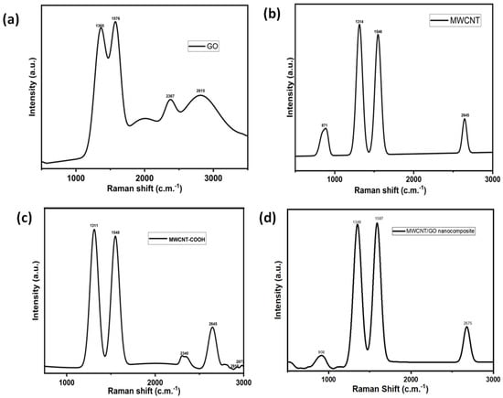
Figure 1.
Raman spectra of (a) GO, (b) MWCNT, (c) MWCNT−COOH, and (d) the MWCNT/GO nanohybrid.
On the other hand, the Raman spectrum of the MWCNT/GO nanohybrid shows peaks at 908 cm−1, 1349 cm−1, 1587 cm−1,, and 2675 cm−1, respectively (Figure 1d). The peak at 1349 cm−1 shows overlapping peaks with GO and MWCNT, causing a significant rise in the D band of the MWCNT/GO nanohybrid in comparison to GO. This might be a result of the excessive carboxylic acid groups introduced during the treatment of MWCNT with aqua regia to increase the compatibility between MWCNT and GO. Moreover, a significant shifting of the G band to 1587 cm−1 was also observed in the MWCNT/GO nanohybrid, indicating an increased degree of graphitization due to the strong pi–pi interaction between the MWCNT and GO. The 2D peak at 2675 cm−1 indicates the formation of a few layers of MWCNT/GO nanohybrid. The presence of various oxygen-containing groups within the graphene oxide and carboxylic acid groups within the MWCNT can be visualized by the FT-IR spectrum as shown in the Figure 2a,b. The FT-IR spectrum of the GO showed characteristic peaks of alkoxy C-O stretching, epoxy -C-O, aromatic C=C, C=O of carbonyl, C-H and –OH at 1080 cm−1, 1410 cm−1, 1625 cm−1, 1785 cm−1, 2960 cm−1, and 3425 cm−1, respectively. On the other hand, the IR spectrum of the acid-functionalized MWCNT shows C=O stretching around 1740 cm−1, corresponding to the carboxylic acid groups on the nanotubes’ surface. The large IR band at 3400 cm−1 and the weak peak at 1632 cm−1 are attributed to asymmetric bending and scissoring vibrations, respectively, due to the trace amount of water present in the KBr pellet used for the measurement.
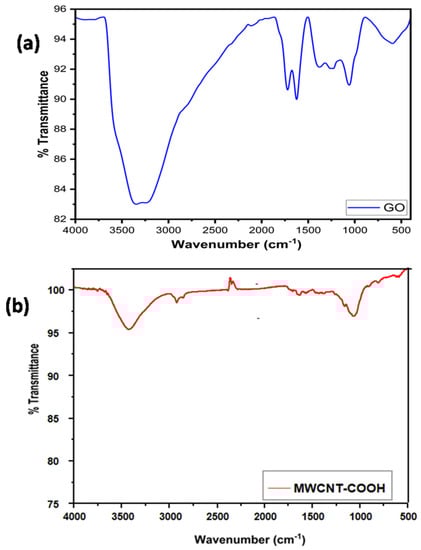
Figure 2.
FT−IR spectra of (a) GO, (b) MWCNT−COOH.
Further, to analyze the surface morphology and thickness of the GO sheets, scanning electron microscopy (SEM) and transmission electron microscopy (TEM) were performed. Figure 3a shows the SEM images of the synthesized GO at a magnification of 1 µm, while Figure 3b shows the hill stack plot corresponding to the surface roughness morphology of the GO sheets. The SEM image of GO depicts stacks of GO sheets with the presence of edge defects as shown by the hill stack plot.
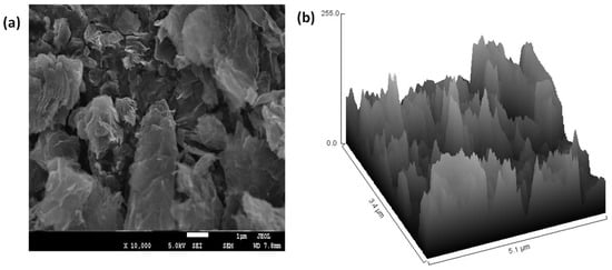
Figure 3.
(a) SEM image of GO, (b) Hill stack plot from the SEM image of GO.
Further, as it is difficult to analyze the thickness of the GO sheets from SEM analysis, TEM analysis was performed to analyze the surface thickness of the GO sheets. Figure 4a depicts the TEM image of the GO sheets at a magnification of 50 nm, which shows the uniform morphology of the GO sheets with an average thickness of 2–3 nm (Figure 4b). Further, the hill stack plot from the TEM image depicts the presence of grain boundaries and edge defects within the GO sheets (Figure 4c).
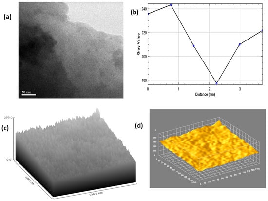
Figure 4.
(a) TEM image of GO, (b) Plot profile diagram from the TEM image of GO, (c) Hill stack plot from the TEM image of GO, (d) 3D surface plot from the TEM image of GO.
The 3D surface morphology of the GO sheets from the TEM image depicts the presence of a 2–3-layer thick flat rough surface with non-uniform particle size and depicts the high degree of exfoliation during the modified Hummers oxidation process (Figure 4d). Both the SEM image and TEM image depict the presence of edge defects and grain boundaries due to the presence of oxygenated groups, which present favorable conditions for the MWCNTs to react with GO to form the MWCNT/GO nanohybrid. This can be seen from the SEM image of MWCNT/GO, where the presence of the MWCNTs is depicted over the matrix of the GO (Figure 5a). Furthermore, the shape index image from the TEM image of MWCNTs/GO demonstrates the distribution of the MWCNTs over the GO matrix, where MWCNTs cover almost every area of the GO sheet, thereby maintaining a good network within the matrix of the GO sheet (Figure 5b).
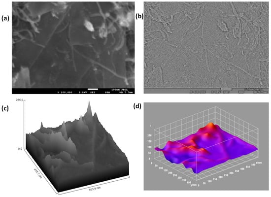
Figure 5.
(a) SEM image of the MWCNT/GO nanohybrid, (b) Shape index plot from the SEM image of the MWCNT/GO nanohybrid, (c) Hill stack plot from the SEM image of the MWCNT/GO nanohybrid, (d) 3D surface plot from the SEM image of the MWCNT/GO nanohybrid.
Furthermore, the hill stack plot from the SEM image of the MWCNT/GO nanohybrid depicts the distribution of MWCNTs over the GO plane, thereby providing a high degree of surface roughness, which increases its super-capacitive properties (Figure 5c). This can also be seen from the 3D surface image (Figure 5d), where MWCNTs are visible in the crest form with the color of a higher wavelength, while the GO sheets are visible in the trough form with the color of a lower wavelength. Both the MWCNTs and the GO sheet thus developed a favorable network to provide high capacitive properties.
One of the regions shows multilayer films of the MWCNT/GO nanohybrid, while the other region shows few-layer films of the nanohybrid. However, it is very important to understand how graphene nanosheets and CNTs make a perfect network to use as a suitable electrode material in thin form for supercapacitor applications. Hence, to understand the interactions between the graphene nanosheets and the CNTs of the synthesized hybrid, we have performed density functional theory (DFT)-based first-principles simulations. A graphene nanosheet and a CNT of similar chirality (4,0) have been fitted into a supercell of 5.98 Å*9.84 Å*4.26 Å size with periodicity ensured in all the three directions. Though the synthesized samples contain multi-walled CNTs, we considered single-walled CNTs in our simulations to reduce the computational cost. The simulations were performed using the DFT code as implemented in Synopsys-Quantum ATK [25]. The exchange-correlation interaction energy of electrons is defined using the local density approximation (LDA) function. The localized double-zeta polarized (DZP) basis sets were employed to describe the valence electrons, and a density mesh cutoff of 75 Hartree was utilized. The structural relaxations of the supercells were performed using a 5*3*6 Monkhorst–Pack grid of K-points, whereas the density of states (DOS) calculations were performed at a higher K-points of 10*6*12 for better accuracy. The structural relaxations (optimizations) were performed using the limited memory Broyden–Fletcher–Goldfarb–Shanno (L-BFGS) algorithm to achieve force and stress tolerance levels of 0.05 eV/Å and 0.1 GPa, respectively.
The simulations were performed for three cases, as shown in Figure 6. In case-1 the pristine versions of graphene and CNT are made to interact with each other, in case-2 the defective graphene sheet is made to interact with pristine CNT, and in case-3 the pristine graphene sheet is made to interact with defective CNT. Here, the defect is created by removing one carbon atom from the material, which is generally referred to as a single-vacancy defect. This kind of defect presents dangling bonds in the material, to enhance its sensitivity towards others. Though several other cases are also possible, we considered only three cases for representative purposes and to demonstrate the point. The interaction strength is estimated using the binding energy (EB) expression given below,
where ECNT, EGraphene, and ECNT + Graphene refer to the energies of the CNT, graphene sheet, and CNT interacting with the graphene sheet, respectively. The calculated binding energies (EB) are mentioned against each interaction case in Figure 6, where a higher binding energy signifies a strong interaction. From case-1, the interaction between the pristine graphene sheet and pristine CNT is very poor, with weak Van der Waals interactions, and resulted in a low binding energy of 1.46 eV. The pristine versions of graphene and CNT exhibit high chemical stability and do not easily bond with others, owing to the inherent aromaticity caused by the delocalization of the π-cloud. As a result, the graphene sheet and CNT do not participate in bonding with each other. In contrast, in case-2 and case-3, the graphene sheet and the CNT are subjected to vacancy defects (disorders), respectively, to disturb the aromaticity and to create dangling bonds. Case-2 and case-3 exhibited strong chemisorption, with high binding energies of 6.01 eV and 3.68 eV, respectively. This implies that the synthesized hybrid has a high number of defects (disorders) through which the graphene and CNTs are bound to each other via chemisorption. The presence of a high number of disorders in the synthesized hybrid was confirmed with help of Raman spectra. To further assess the influence of these defects (disorders) on the electronic and capacitive properties, we have extracted the electronic density of states (DOS) and quantum capacitance of the hybrids shown in case-2 and case-3 of Figure 6.
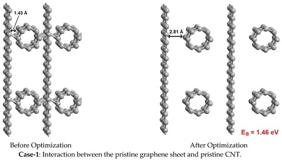
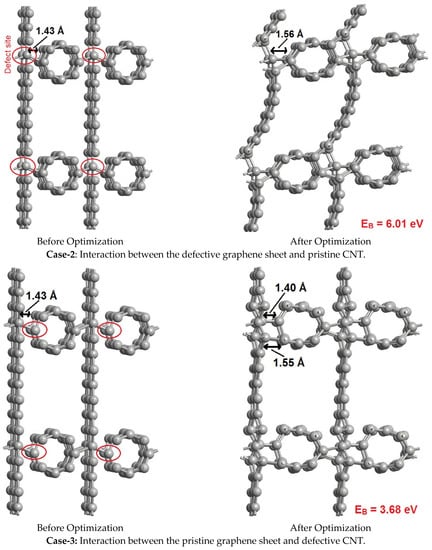
Figure 6.
Interactions between pristine as well as defective graphene sheets and CNT.
Besides the hybrid, the DOS profiles were extracted for the pristine graphene sheet and pristine CNT, which were used to design the hybrid, to verify the accuracy of the method. From Figure 7, the DOS profile of pristine graphene shows a perfect zero band gap with a Dirac cone structure located at the Fermi level. This confirms the accuracy of the utilized method. The DOS profiles of the hybrids show various defect-induced states along the energies of the valance and conduction bands. To understand the impact of these defect-induced states on the capacitive performance of supercapacitor electrodes, we have computed the quantum capacitance of these hybrids from their DOS profiles using MATLAB programming [26].
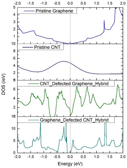
Figure 7.
Density−of−states (DOS) profiles of the pristine graphene sheet, pristine CNT, defective graphene + pristine CNT hybrid, and pristine graphene + defective CNT hybrid.
The quantum capacitance (CQ), which depends on the DOS (D(E)), is given by [27,28],
where
Here, K is Boltzmann’s constant, T is temperature, E is energy, e is the elementary charge (1.6*10−19 Coulombs), and V is the applied electrode voltage. The quantum capacitances are plotted in Figure 8 over a voltage range of −0.6 V to 0.6 V as standard practice, which is the typical electrochemical window of aqueous electrolyte. Both the representative hybrids exhibited very high quantum capacitances over the electrochemical window. The defective graphene + pristine CNT hybrid exhibited a peak quantum capacitance of 85.72 μF/cm2 at 0.4 V, whereas the pristine graphene + defective CNT hybrid exhibited a peak quantum capacitance of 69.04 μF/cm2 at −0.4 V. These quantum capacitances are several times higher than the quantum capacitance offered by a pristine graphene sheet, as reported elsewhere [29]. Moreover, the hybrids show high quantum capacitances on the positive as well as negative sides of the bias window, inferring their suitability for the design of high-performance symmetric supercapacitors.
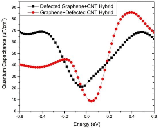
Figure 8.
Quantum capacitance (CQ) of the defective graphene + pristine CNT hybrid and the pristine graphene + defective CNT hybrid electrodes.
Electrochemical Performance
Cyclic voltammetry (CV) analysis based on the two-electrode system was performed to understand the electrochemical behavior of the device at different scan rates: 2 mVs−1, 5 mVs−1, 10 mVs−1, 20 mVs−1, 50 mVs−1, 100 mVs−1, and 200 mVs−1 (Figure 9a). The obtained CV plot shows the traditional double-layer pattern of the device, which may be attributed to the fine coating of the material over the surface of current collectors. A fine coating of the materials has increased the ionic transportation around the surface of the electrode materials which is directly proportional to the conductivity of the ions. Thus, the fine coating is the major reason behind the double-layer pattern of these electrodes. However, to ensure the theoretical evaluation, we have calculated the specific capacitance of thin electrode devices at different scan rates, and the values are shown in Table 1.
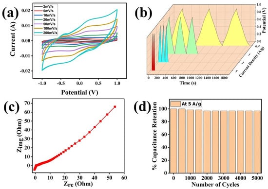
Figure 9.
(a) Cyclic voltammetry of the thin-film electrode, (b) GCD plot of the thin−film electrode, (c) EIS plot of the thin−film electrode, (d) Specific capacitance retention of the thin−film electrode.

Table 1.
Specific capacitance calculated using CV plots of the thin electrode device.
Equation (4), depicted below, has been used for the calculation of specific capacitance (Cs) from CV plots [30].
Here, A represents the integrated absolute area of the CV plot, m is the mass coated onto electrodes in mg, K is the scan rate in mVs−1, and V is the voltage at which the CV test was performed.
Our calculations show the tremendous potential of the thin electrode-based devices, with a maximum specific capacitance of 369.01 Fg−1 observed at a 2 mVs−1 scan rate (Table 1). Moreover, the specific capacitance remained ~79 Fg−1 at a very high scan rate of 200 mVs−1, which may be due to the slowness of electrolytic ions moving towards the holes in the electrode material at higher scan rates [31].
Next, galvanic charge–discharge (GCD) analysis was performed to evaluate the charging–discharging behaviors of the device. Here, GCD analysis was performed at different current densities of 0.5 Ag−1, 1 Ag−1, 2 Ag−1, and 5 Ag−1 over a wide potential range, i.e., 0–1 V (Figure 9b). The GCD plot is specifically used for the evaluation of the charging behavior of any energy storage device and can also be used to evaluate the cycle life of the fabricated device along with specific capacitance. Thus, we have used Equation (2) for the calculation of specific capacitance from the GCD data; moreover, the cyclic stability of the device has also been analyzed (Figure 9b,d, Table 2).
Table 2.
Specific capacitance evaluated using GCD plots.
The triangular symmetry of each GCD plot predicts good capacitive behavior for the device, which further supports the CV data. The specific capacitance from GCD was evaluated using Equation (5) [21]:
Here, i is the current, m is the mass coated onto the electrodes, and Δt/Δ represents the linear slope of the discharge curve. The highest specific capacitance estimated from the GCD data is 155.75 Fg−1 at a current density of 0.5 Ag−1, which has been tabulated in Table 2 along with other values.
Additionally, the fabricated device shows an excellent energy density (ED) of 21.63 Whkg−1 at a current density of 0.5 Ag−1, which has been tabulated in Table 3 along with other values. Energy density (ED) values were calculated using the formula shown in Equation (6).
Table 3.
The energy and power densities for different current densities.
Here, Cs denotes the specific capacitance and V is the voltage.
Additionally, the power densities (PD) were also calculated using Equation (7), and the values are tabulated in Table 3.
Here, ED represents the energy density and Δt is the time consumed.
Furthermore, electrochemical impedance spectroscopy was performed to evaluate the impedance of the device. Impedance is a relative measure of resistance in the DC circuit. Figure 9c shows the Nyquist plot, which is plotted between the imaginary impedance and the real impedance of the device. The slight steepness at the beginning of the Nyquist plot in low-frequency regions predicts the good capacitive potential of the material. However, the anomalous behavior of the curve at a higher frequency range may be attributed to the high impedance value of the material [22]. The specific capacitance was also calculated using EIS data which, was found to be about 240.9 Fg−1 at the frequency range of 0.01 Hz to 106 Hz using Equation (8).
Here, Cs is the specific capacitance, f is the initial frequency of the applied signal, Z″ is the imaginary part, and Z′ is the real part of the impedance. Finally, the cyclic stability of the fabricated device was tested for up to 5000 cycles at a current density of 5 Ag−1, which is depicted in Figure 9d. The device shows an excellent cycle retention of more than 97% even after 5000 cycles of charging and discharging. The electrochemical performance testing of this thin-film electrode shows its superior suitability for supercapacitor devices, supported by its high specific capacitance and high energy as well as power densities.
3. Material and Methods
3.1. Materials
All the materials were used as received. MWCNT and expanded graphite powders were purchased from Sigma Aldrich. KMnO4, H2SO4, HCl, HNO3, NaNO3, DMF, n-hexane, and H2O2 were purchased from Himedia.
3.2. Synthesis of Graphene Oxide (GO)
Synthesis of the graphene oxide (GO) was done by adopting the procedure of the modified Hummer method [31]. Briefly, graphite was taken as the precursor material, and KMnO4 in the presence of concentrated H2SO4 was taken as an oxidizing agent for the oxidation of the graphite sheets. A total of 2 g of graphite, 12 g of KMnO4, and 6 g of NaNO3 were taken in a 500 mL beaker container, then 125 mL of H2SO4 was added slowly into the beaker with the help of glass rod and stirred continuously for five hours in an ice-water environment. Later, 1000 mL of distilled water was poured into the reaction system and stirred again for 1 h, until a brown color was seen in the reaction system. Finally, 12 mL of H2O2 was added to the reaction system to quench the reaction followed by washing with distilled water to remove the ionic impurities present within the system and to maintain a pH of 7, via a centrifugation process.
3.3. Synthesis of MWCNT/GO Nanohybrids
Synthesis of the MWCNTs/GO nanohybrid was done by intermixing the functionalized MWCNT and GO via the solution-mixing method. Firstly, MWCNTs were functionalized with the carboxylic acid group by treating MWCNT with aqua regia as reported in the literature [32]. Briefly, 0.5 g of MWCNTs were treated with 125 mL of 6 M aqua regia and sonicated for 15 min followed by refluxing for 6 hr. Thereafter, the solution of MWCNTs was filtered through suction filtrate with 0.2 µm filter paper and, subsequently, the black residue thus obtained was dried inside the oven at 100 °C. Thus obtained functionalized MWCNTs (f-MWCNTs) were added to 50 mL of diluted GO (dispersed in distilled water), with the mass ratio of 1:3 (f-MWCNTs: GO), to achieve maximum dispersibility [19] and then sonicated for 8 hr. The resulting solution mixture is our MWCNTs/GO nanohybrid.
3.4. Thin Film Preparation of MWCNT/GO Nanohybrids
After the preparation of the MWCNT/GO nanohybrid, the fabrication of thin films of the MWCNT/GO nanohybrid was done by using the solvent–antisolvent technique for supercapacitor application (Figure 10). Initially, the dispersion of the MWCNT/GO nanohybrid was done using a mixture of n-hexane and DMF through an ultrasonication process at 45 Khz. In this dispersion, DMF acts as a solvating agent for the MWCNT/GO nanohybrid, while n-hexane acts as an anti-solvating agent that separates the layers of the MWCNT/GO nanohybrid. Therefore, a partial conical separation was also seen at the interface of the solvent and antisolvent system. However, on shaking off the existing interfacial media, several bubbles of the individual nanohybrid were seen, with the most favorable coordination number of six. These nanohybrid bubbles, on coalescence at the water surface, yield thin layers of MWCNT/GO nanohybrid. When a dispersed solution of MWCNT/GO nanohybrid is put over an azeotropic mixture/antisolvent, the formation of films takes place, due to the high repulsion force during the phase transfer; i.e., as soon as the dispersed nanohybrid meets the two different phases of water and hexane, the nanohybrid aligns itself in such a way to minimize the cohesive forces and minimize the surface energy. This results in the self-alignment of the nanohybrid to form a uniform film.
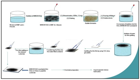
Figure 10.
Schematic scheme for the preparation of MWCNT/GO nanohybrid thin films on a glass substrate via the solvent-antisolvent technique.
To further explain the formation of thin films, the nanohybrid is dispersed in an aprotic solvent, i.e., either in DMSO or DMF, uniformly. When this mixture meets a mixture of water and hexane, the aprotic solvent from the dispersed nanohybrid solution shows a very high affinity for water and leaves behind the nanohybrid in an unbounded manner. The strong van der Waal forces are then activated quickly among the nanohybrids, forcing them into self-alignment, forming thin films to minimize the surface energy. The film spreads over as large an area as possible due to this phenomenon. However, the layer formed over the water surface depends upon several factors, such as the ratio of water to n-hexane, ultrasonication time, frequency, and shaking of the interfacial media. It was observed during the experiment that an equimolar ratio of DMF and n-hexane with an ultrasonication time of 15 min at 45 kHz and vigorous shaking for 2 min gives the best results. Further, TLC silica gel plates F254 were used to extract the layer thus fabricated over the surface of the water. Here, the capillary action and high affinity of n-hexane for the silica plates induce the driving force needed for the uplifting of the thin film layer. Later, the hexane splits out from the surface of the silica plate when it encounters water (Figure 11), then the thin film is uplifted in the desired substrate (glass or graphite). In the present case, graphite was taken as the substrate, as the supercapacitor device was fabricated by taking graphite as the substrate for the electrode, while a glass-based substrate was used to check the homogeneity of the fabricated material under the optical microscope.
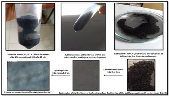
Figure 11.
The process diagram for the dispersion and thin film formation of the MWCNT/GO nanohybrid.
The uplifted thin film of MWCNT/GO over the glass substrate was investigated with the help of optical microscopy. The results obtained from the optical microscopy show two different regions of layer formation (Figure 12).
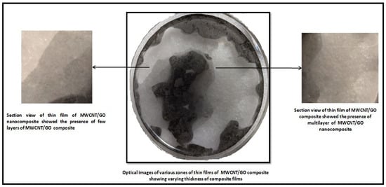
Figure 12.
Optical image of the thin film of MWCNT/GO nanohybrid with a section view of the varying thickness of the film.
3.5. Physico-Chemical Characterization
The characterization of the thus-prepared MWCNT/GO nanohybrid was mainly investigated by Raman spectroscopy using a Renishaw Raman Microscope with a spectral wavelength of 532 nm and FT-IR spectra (using Perkin Elmer, spectra-2, Waltham, MA, USA) to understand the functional behavior of the nanohybrid. Optical microscopy was used to analyze the morphology of the layered structure of MWCNT/GO nanohybrids.
3.6. Preparation of Electrodes and Electrochemical Analysis
The thin films of MWCNTs/GO nanohybrids were used to fabricate a binder-free supercapacitor. Two electrodes of 1 × 1 cm2 area were prepared using a graphite sheet having a thickness of 2.5 mm, which was used as a substrate for the uplifting of the MWCNTs/GO thin films. First, one of the graphite substrates was held tightly with the help of a pointed tweezer and dipped inside the water-based system at an angle of 180°, as shown in Figure 1. The graphite substrate was used in this case instead of glass. The graphite sheet was then slowly uplifted with an inclination angle that varied from 180° to 90° until a homogeneous sheet of MWCNTs/GO was overlapped over the graphite sheet. Then, the graphite sheet with MWCNTs/GO was dried at 60 °C inside an oven for 1 hr. Finally, the dried MWCNT/GO deposited graphite substrates (~1 mg per electrode) were used for the fabrication of the supercapacitors, where 1 M H2SO4 was used as the electrolyte for the whole process by using Whatman filter (pore size 0.45 µm) paper as the separator.
The supercapacitor behavior of the thin films of the MWCNTs/GO nanohybrid was analyzed via the two-electrode system of an electrochemical station (Metrohm Autolab, Utrecht, Netherlands). Cyclic voltammetry (CV) analysis was performed for the fabricated thin-film electrodes at scan rates of 2 mVs−1 to 200 mVs−1 at the potential window of −1 V to 1.0 V by using a 1 M H2SO4 electrolyte system. Impedance spectroscopy was performed at 10 mHz and the galvanostatic charging–discharging measurements were carried out on the potential window of 0–1 V at the current densities of 0.5, 1, 2, and 5 Ag−1. Again, the specific capacitance of the MWCNT/GO nanohybrid-based device was calculated by using CV, electrochemical impedance spectroscopy (EIS), and galvanostatic charge–discharge charge (GCD) techniques [33].
4. Conclusions
The present work reports a facile method for the synthesis of MWCNT/GO nanohybrid thin films for energy storage applications. A solvent–antisolvent technique was utilized in this method for the fabrication of electrodes. Further, the process turns out to be a cost-effective technique, as the solvent used during the process could be recycled several times. Density functional theory (DFT)-based computational investigations demonstrated the enhanced quantum capacitance of the MWCNT/GO nanohybrid. Inspired by the computational results, the MWCNT/GO nanohybrid thin films were used to fabricate binder-free supercapacitor devices. The electrochemical performance of the MWCNTs/GO nanohybrid with 1 M aqueous H2SO4 electrolyte demonstrates an excellent energy density of 21.63 WhKg−1 on a 249.5 WKg−1 power density at a current density of 0.5 Ag−1 and a high specific capacitance of 369.01 F/g−1 at a scan rate of 2 mVs−1. Furthermore, the fabricated device showed excellent stability of more than 97% capacitance retention over 5000 charge-discharge cycles, which enhances the value of the thus-fabricated thin film and device in practical supercapacitor applications. Therefore, the present work showcases the potential of the solvent–antisolvent technique for the fabrication of lightweight and binder-free thin film electrode-based supercapacitors.
Author Contributions
Conceptualization, S.P.; data curation, S.P., M.P. and G.T.; formal analysis, M.K., G.T. and S.D.; funding acquisition, N.G.S.; investigation, S.P., B.S., P.S.D., A.S. and N.G.S.; methodology, S.P. and M.P.; resources, N.G.S.; software, B.S. and A.S.; supervision, N.G.S.; validation, M.K., B.S., P.S.D. and S.R.; visualization, A.S., S.R. and N.G.S.; writing—original draft, S.P.; writing—review and editing, S.P., M.P. and S.R. All authors have read and agreed to the published version of the manuscript.
Funding
This research was funded by NMHS, GBPHIED, Kosi Katarmal, Almora, grant number [GBPNI/NMHS-2019-20/MG] and DST INSPIRE Division, New Delhi, India, grant number (IF180347).
Data Availability Statement
The data that support the findings of this study are available on reasonable request from the corresponding author.
Acknowledgments
The authors acknowledge DST-INSPIRE Division New Delhi, India, and NMHS, GBPHIED, Kosi Katarmal, Almora for providing the necessary support for the work.
Conflicts of Interest
The authors declare no conflict of interest.
References
- Dubal, D.; Ayyad, O.; Ruiz, V.; Gomez-Romero, P. Hybrid energy storage: The merging of battery and supercapacitor chemistries. Chem. Soc. Rev. 2015, 44, 1777–1790. [Google Scholar] [CrossRef] [PubMed]
- Kyeremateng, N.; Brousse, T.; Pech, D. Microsupercapacitors as miniaturized energy-storage components for on-chip electronics. Nat. Nanotechnol. 2017, 12, 7–15. [Google Scholar] [CrossRef] [PubMed]
- Miller, J.; Simon, P. Electrochemical capacitors for energy management. Sci. Mag. 2008, 321, 651–652. [Google Scholar] [CrossRef] [PubMed]
- Lu, X.; Yu, M.; Wang, G.; Tong, Y.; Li, Y. Flexible solid-state supercapacitors: Design, fabrication and applications. Energy Environ. Sci. 2014, 7, 2160–2181. [Google Scholar] [CrossRef]
- Yu, M.; Lin, D.; Feng, H.; Zeng, Y.; Tong, Y.; Lu, X. Boosting the energy density of carbon-based aqueous supercapacitors by optimizing the surface charge. Angew. Chem. 2017, 129, 5546–5551. [Google Scholar] [CrossRef]
- Wang, F.; Wu, X.; Yuan, X.; Liu, Z.; Zhang, Y.; Fu, L.; Zhu, Y.; Zhou, Q.; Wu, Y.; Huang, W. Latest advances in supercapacitors: From new electrode materials to novel device designs. Chem. Soc. Rev. 2017, 46, 6816–6854. [Google Scholar] [CrossRef]
- Wang, G.; Zhang, L.; Zhang, J. A review of electrode materials for electrochemical supercapacitors. Chem. Soc. Rev. 2012, 41, 797–828. [Google Scholar] [CrossRef]
- Li, H.; Hou, Y.; Wang, F.; Lohe, M.; Zhuang, X.; Niu, L.; Feng, X. Flexible all-solid-state supercapacitors with high volumetric capacitances boosted by solution processable MXene and electrochemically exfoliated graphene. Adv. Energy Mater. 2017, 7, 1601847. [Google Scholar] [CrossRef]
- Park, S.; Ruoff, R. Chemical methods for the production of graphenes. Nat. Nanotechnol. 2009, 4, 217–224. [Google Scholar] [CrossRef]
- El-Kady, M.; Kaner, R. Scalable fabrication of high-power graphene micro-supercapacitors for flexible and on-chip energy storage. Nat. Commun. 2013, 4, 1475. [Google Scholar] [CrossRef]
- El-Kady, M.; Strong, V.; Dubin, S.; Kaner, R. Laser scribing of high-performance and flexible graphene-based electrochemical capacitors. Science 2012, 335, 1326–1330. [Google Scholar] [CrossRef] [PubMed]
- Wu, Z.; Parvez, K.; Feng, X.; Müllen, K. Graphene-based in-plane micro-supercapacitors with high power and energy densities. Nat. Commun. 2013, 4, 2487. [Google Scholar] [CrossRef] [PubMed]
- Wu, Z.; Liu, Z.; Parvez, K.; Feng, X.; Müllen, K. Ultrathin printable graphene supercapacitors with AC line-filtering performance. Adv. Mater. 2015, 27, 3669–3675. [Google Scholar] [CrossRef] [PubMed]
- Liu, Z.; Wu, Z.; Yang, S.; Dong, R.; Feng, X.; Müllen, K. Ultraflexible in-plane micro-supercapacitors by direct printing of solution-processable electrochemically exfoliated graphene. Adv. Mater. 2016, 28, 2217–2222. [Google Scholar] [CrossRef] [PubMed]
- Yoo, J.; Balakrishnan, K.; Huang, J.; Meunier, V.; Sumpter, B.; Srivastava, A.; Conway, M.; Reddy, A.M.; Yu, J.; Vajtai, R. Ultrathin planar graphene supercapacitors. Nano Lett. 2011, 11, 1423–1427. [Google Scholar] [CrossRef]
- Wu, Z.; Parvez, K.; Winter, A.; Vieker, H.; Liu, X.; Han, S.; Turchanin, A.; Feng, X.; Müllen, K. Layer-by-layer assembled heteroatom-doped graphene films with ultrahigh volumetric capacitance and rate capability for micro-supercapacitors. Adv. Mater. 2014, 26, 4552–4558. [Google Scholar] [CrossRef]
- Zhou, F.; Huang, H.; Xiao, C.; Zheng, S.; Shi, X.; Qin, J.; Fu, Q.; Bao, X.; Feng, X.; Mu, K. Electrochemically scalable production of fluorine-modified graphene for flexible and high-energy ionogel-based microsupercapacitors. J. Am. Chem. Soc. 2018, 140, 8198–8205. [Google Scholar] [CrossRef]
- Weng, Z.; Su, Y.; Wang, D.; Li, F.; Du, J.; Cheng, H. Graphene–cellulose paper flexible supercapacitors. Adv. Energy Mater. 2011, 1, 917–922. [Google Scholar] [CrossRef]
- Zhang, L.; Zhao, X.; Stoller, M.; Zhu, Y.; Ji, H.; Murali, S.; Wu, Y.; Perales, S.; Clevenger, B.; Ruoff, R. Highly conductive and porous activated reduced graphene oxide films for high-power supercapacitors. Nano Lett. 2012, 12, 1806–1812. [Google Scholar] [CrossRef]
- Wu, Z.-S.; Yang, S.; Zhang, L.; Wagner, J.; Feng, X.; Müllen, K. Binder-free activated graphene compact films for all-solid-state micro-supercapacitors with high areal and volumetric capacitances. Energy Storage Mater. 2015, 1, 119–126. [Google Scholar] [CrossRef]
- Zhu, C.; Liu, T.; Qian, F.; Chen, W.; Chandrasekaran, S.; Yao, B.; Song, Y.; Duoss, E.; Kuntz, J.; Spadaccini, C. 3D printed functional nanomaterials for electrochemical energy storage. Nano Today 2017, 15, 107–120. [Google Scholar] [CrossRef]
- Zhang, F.; Wei, M.; Viswanathan, V.; Swart, B.; Shao, Y.; Wu, G.; Zhou, C. 3D printing technologies for electrochemical energy storage. Nano Energy 2017, 40, 418–431. [Google Scholar] [CrossRef]
- Wang, B.; Qiu, J.; Feng, H.; Sakai, E. Preparation of graphene oxide/polypyrrole/multi-walled carbon nanotube nanohybrid and its application in supercapacitors. Electrochim. Acta 2015, 151, 230–239. [Google Scholar] [CrossRef]
- Mao, X.; Xu, J.; He, X.; Yang, W.; Yang, Y.; Xu, L.; Zhao, Y.; Zhou, Y. All-solid-state flexible microsupercapacitors based on reduced graphene oxide/multi-walled carbon nanotube composite electrodes. Appl. Surf. Sci. 2018, 435, 1228–1236. [Google Scholar] [CrossRef]
- QuantumATK, Synopsys QuantumWise A/S. Available online: https://www.synopsys.com/silicon/quantumatk.html (accessed on 1 January 2023).
- MATLAB, The MathWorks Inc. Available online: https://www.mathworks.com (accessed on 1 January 2023).
- Srivastava, A.; SanthiBhushan, B. Trade-off between quantum capacitance and thermodynamic stability of defected graphene: An implication for supercapacitor electrodes. Appl. Nanosci. 2018, 8, 637–644. [Google Scholar] [CrossRef]
- Pandey, S.; Karakoti, M.; Surana, K.; Dhapola, P.; SanthiBhushan, B.; Ganguly, S.; Singh, P.; Abbas, A.; Srivastava, A.; Sahoo, N. Graphene nanosheets derived from plastic waste for the application of DSSCs and supercapacitors. Sci. Rep. 2021, 11, 1–17. [Google Scholar] [CrossRef]
- Ponomarenko, L.; Yang, R.; Gorbachev, R.; Blake, P.; Mayorov, A.; Novoselov, K.; Katsnelson, M.; Geim, A. Density of states and zero Landau level probed through capacitance of graphene. Phys. Rev. Lett. 2010, 105, 136801. [Google Scholar] [CrossRef]
- Pandey, S.; Karakoti, M.; Chaudhary, N.; Gupta, S.; Kumar, A.; Dhali, S.; Patra, A.; Singh, R.; Sahoo, N. Single Step Blending of PEDOT: PSS/SPGO Nanocomposite via low temperature solid phase addition of graphene oxide for effective hole transport layer in organic solar cells. J. Nanosci. Nanotechnol. 2020, 20, 3888–3895. [Google Scholar] [CrossRef]
- Pathak, M.; Tatrari, G.; Karakoti, M.; Pandey, S.; Sahu, P.; Saha, B.; Sahoo, N. Few layer graphene nanosheets from kinnow peel waste for high-performance supercapacitors: A comparative study with three different electrolytes. J. Energy Storage 2022, 55, 105729. [Google Scholar] [CrossRef]
- Matiyani, M.; Pathak, M.; Bohra, B.; Sahoo, N. Noncovalent Functionalization of Carbon Nanotubes, Handbook of Carbon Nanotubes; Springer: Berlin/Heidelberg, Germany, 2021; pp. 1–28. [Google Scholar]
- Pandey, G.; Rastogi, A. Graphene-Based All-Solid-State Supercapacitor with Ionic Liquid Gel Polymer Electrolyte. MRS Online Proc. Libr. Symp. O – Next-Gener. Energy Storage Mater. Syst. 2012, 1440. [Google Scholar]
Disclaimer/Publisher’s Note: The statements, opinions and data contained in all publications are solely those of the individual author(s) and contributor(s) and not of MDPI and/or the editor(s). MDPI and/or the editor(s) disclaim responsibility for any injury to people or property resulting from any ideas, methods, instructions or products referred to in the content. |
© 2023 by the authors. Licensee MDPI, Basel, Switzerland. This article is an open access article distributed under the terms and conditions of the Creative Commons Attribution (CC BY) license (https://creativecommons.org/licenses/by/4.0/).