Abstract
This study presents the results of electrochemical investigations on Hydrogen and Oxygen Evolution Reactions (HER and OER), conducted on commercially available carbon fibres and nickel-coated carbon fibres modified using nanoscale NiFe alloy particles in 0.1 M of NaOH solution. The obtained results demonstrated enhanced catalytic activity of the NiFe-modified fibre materials, with approximately 14,700% and 25% improvement in the OER and HER activity (respectively), as compared to unmodified electrodes. The catalytic properties were evaluated by means of electrochemical impedance spectroscopy, Tafel polarisation and cyclic, and linear voltammetry techniques. The deposited particles’ distribution and quantities present on the investigated materials were analysed using Scanning Electron Microscopy (SEM) and Energy-Dispersive X-ray spectroscopy (EDX) methods. These findings provided valuable insights into the electrochemical, catalytic performance of NiFe-modified carbon fibre/nickel-coated carbon fibre materials, simultaneously highlighting their potential application as catalyst materials for electrodes in industrial-scale water electrolysers.
1. Introduction
As the world faces an energy crisis and serious challenges associated with climate change, researchers continue searching for new solutions and alternatives in order to replace conventional fossil fuels [1,2,3]. Hydrogen’s high energy density makes it a promising alternative fuel solution. Moreover, its combustion results in the formation of just water molecules, which is accompanied by energy release in the form of heat (Equation (1)). Unfortunately, a significant portion (95%) of hydrogen is currently produced by means of methods that rely on fossil fuels (methane, coal, and oil), through steam methane reforming or coal gasification, leading to significant carbon dioxide emissions. This type of hydrogen is commonly known as “gray hydrogen”. On the other hand, water electrolysis (e.g., realised via PEM: proton exchange membrane or AWE: alkaline water electrolysis process) combined with renewable energy sources (e.g., solar, wind or water) enables hydrogen production to become emission-free, where such generated H2 is called “green hydrogen” [4,5,6].
2H2 + O2→ 2H2O + Q
Due to the acidic environment prevailing inside the PEM electrolyser cell, these systems could only utilise catalysts that are highly stable (corrosion-resistant) at low pH values, i.e., predominantly composed of very costly, semi-noble, and noble metal particles. In contrast, the alkaline (AWE) systems enable the utilisation of cheaper and more available transition elements, such as Fe, Ni, Co, Cu, etc. However, these metals are generally less catalytic towards either of the discussed gas evolution reactions than those of noble/semi-noble nature. This necessitated a search for new materials that could lower hydrogen production costs by reducing the overall energy consumption for the water electrolysis process [7,8,9,10]. Current AWE scientific activities are primarily focused on the investigation of the catalytic performance of different forms of Ni, Fe, and Co elements. Of particular interest are materials derived from their respective oxides and hydroxides, as well as various alloy compositions containing these elements. Thus, their chemical compositions and synthesis methods are being continuously analysed and are subject to ongoing discussions within the scientific community [11,12,13,14,15,16,17,18,19,20].
Recently, special attention has been given to NiFe-LDH (NiFe Layered Double Hydroxide)-based materials, which exhibit superior catalytic properties and achieve high current densities towards the HER and OER reactions. Additionally, notable materials, such as NiSn, NiCoSn, NiCu, MoS, NiAg, and CoP demonstrate similar catalytic properties to Pt in the context of the HER [11,20,21,22,23,24]. Furthermore, when analysing the OER catalysts, it is worthwhile (besides the NiFe alloy) to consider materials such as CoP, NiCoO, and NiCo-LDH, which also demonstrate promising catalytic properties [14,17,18].
This work aims to shed light on the behaviour of NiFe catalysts on commercially available carbon fibre (CF) and nickel-coated carbon fibre (NiCCF) materials, and serves as a preliminary investigation for further studies, enabling the practical implementation of NiFe alloys in industrial-scale electrolysers. The authors’ decision to combine Ni-coated carbon fibres (or carbon fibres) with NiFe alloy was inspired by the potential of leveraging the inherent electrochemical properties of both materials. While NiCCF and CF offer robust and conductive support materials, NiFe alloy particles further enhance their catalytic (HER, OER) activities. It should also be stressed here that the current work takes direct advantage of a number of previously published articles from this laboratory on the HER behaviour of CF and NiCCF tow catalyst materials (see Refs. [25,26,27,28,29]). Specifically, the CF (NiCCF) and NiFe catalyst combination aims to address the challenges associated with single-material systems and seeks to optimize the performance of both the HER and OER reactions under alkaline conditions.
2. Results and Discussion
2.1. SEM/EDX Characterisation of CF, NiCCF, NiFe/CF and NiFe/NiCCF Electrodes
Figure 1a–c and Figure 2a–c show that the structures of the deposited NiFe alloy were of somewhat non-regular and discontinuous structure based on the base material’s surface. The grain size of the deposited alloy fluctuated between 40–60 nm with visible agglomerates of NiFe particles reaching sizes up to 150 nm. NiFe alloy content in the NiFe/CF samples was ca. 10 wt.% (assessed by a weighing method and the SEM coupled with EDX spectroscopy evaluations). The weighing method showed the same results for the NiFe/NiCCF sample, as for the NiFe/CF specimen. For the SEM/EDX analysis, notable discrepancies were observed in the percentage composition of individual elements (see Table 1). The above could be attributed to the presence of a homogeneous nickel coating, which impairs the accessibility of carbon during the SEM/EDX examination. The total composition and arrangement of elements of the NiFe/CF, NiCCF, and NiFe/NiCCF electrodes is shown in Table 1 and Figure 1 and Figure 2.
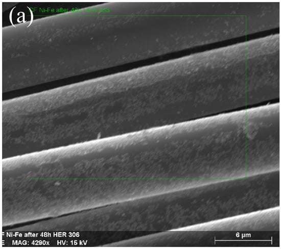
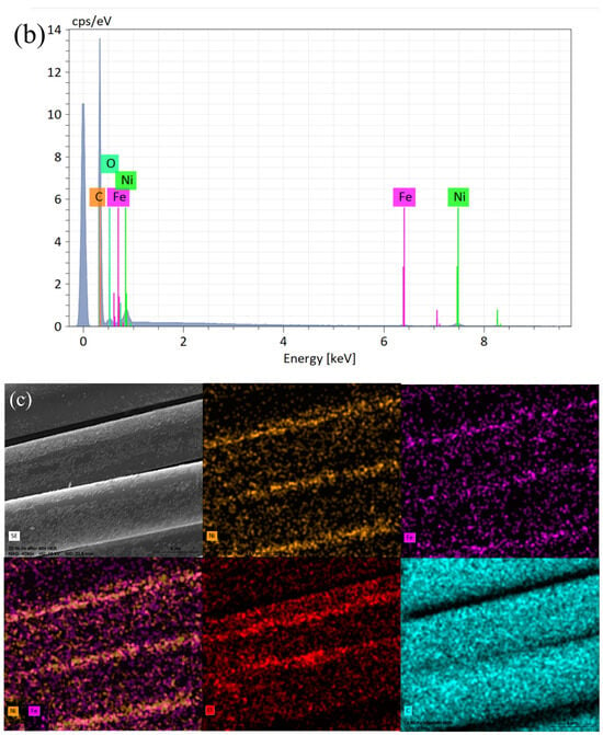
Figure 1.
SEM micrograph pictures of NiFe/CF (a), taken at 4290× magnification with EDX pattern (b) and EDX elemental mappings (c).
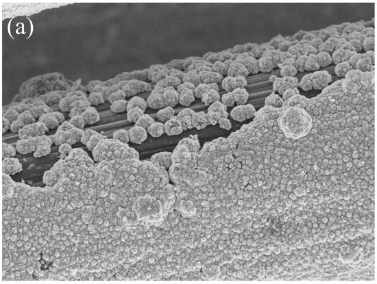
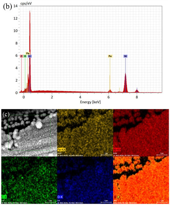
Figure 2.
SEM micrograph pictures of NiFe/NiCCF (a), taken at 50,000× magnification with EDX pattern (b) and EDX elemental mappings (c).

Table 1.
EDX-derived (for an acceleration voltage of 15 kV) chemical composition of surface elements for NiFe/CF, NiCCF, and NiFe/NiCCF samples.
2.2. Electrochemical Characterisation
2.2.1. Cyclic Voltammetry
The cyclic voltammetry (CV) graphs present a comparison of electrochemical behaviour for all examined electrodes (CF, NiCCF, NiFe/CF, and NiFe/NiCCF) in 0.1 M NaOH solution (three sweeps were carried out over the potential span of −1.0–1.8 V vs. RHE with a scan-rate of 50 mV s−1—the last cycles are presented) in Figure 3a,b. The deposition of NiFe alloy on the surfaces of CF and NiCCF materials resulted in a significant enhancement of the HER and OER catalysis. Additionally, the recorded cyclic voltammograms for the NiFe/CF electrodes exhibited two anodic (A, B) and three cathodic (C, D, E) peaks (see marked peaks in Figure 3: A (0–700 mV), B (1400–1700 mV), C (1000–1500 mV), D (350–700 mV) and E (−100–300 mV)). Peak A corresponds to the oxidation of iron (Equations (2)–(4)) and nickel (Equations (5)–(7), where α-Ni(OH)2 ageing is applied; see Bode cycle diagram in Figure 12 of Ref. [30] for more details) along with the corresponding reduction peaks D (Fe3+/Fe2+) and E [Fe2+/Fe0 and Ni(OH)2/Ni0]. On the other hand, peak B is related to the formation of β-NiOOH oxyhydroxide phase (Equation (8)); peak C corresponds to its reduction (β-NiOOH/β-Ni(OH)2) [31,32,33,34,35,36,37,38]. However, as no ageing was applied in this work to in situ formed nickel hydroxide, its significant portion would further be converted upon charging to form γ-NiOOH phase (Equation (9)). Hence, the recorded peaks B/C in Figure 3a most likely correspond to mixed features of β-NiOOH/β-Ni(OH)2 and γ-NiOOH/α-Ni(OH)2 transitions.
Fe0 → Fe2+ + 2e−
Fe0 + 2OH− → Fe(OH)2 + 2e−
Fe2++ 3OH− → Fe(OH)3 + e−
Ni0 + 2OH− → α-Ni(OH)2 + 2e−
α-Ni(OH)2 → β-Ni(OH)2
Ni0 + 2OH− → β-Ni(OH)2 + 2e−
β-Ni(OH)2 + OH− → β-NiOOH + H2O + e−
α-Ni(OH)2 + OH− → γ-NiOOH + H2O + e−
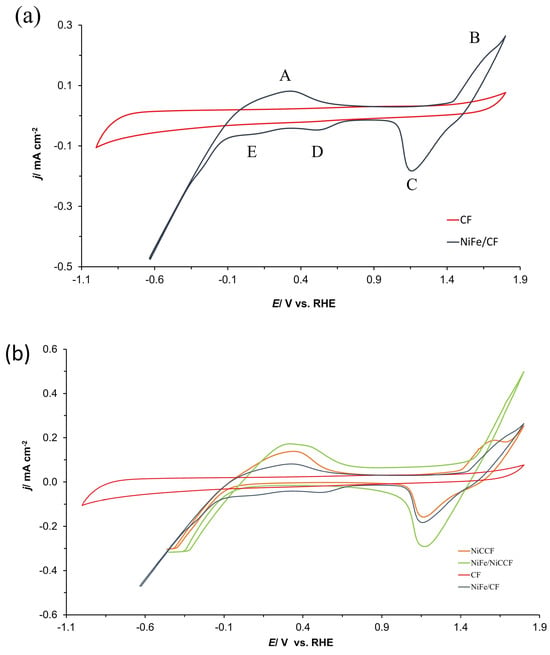
Figure 3.
Cyclic voltammogram curves of (a) CF and NiFe/CF; (b) CF, NiCCF, NiFe/CF, and NiFe/NiCCF electrodes in contact with 0.1 M NaOH medium, carried out at a scan-rate of 50 mV s−1 over the potential span from −1.0 to 1.8 V vs. RHE.
Figure 4 presents the cyclic voltammetry (CV) curves for all examined fibre-based electrodes. The comparison reveals noticeable differences among the samples. Specifically, as expected for the unmodified NiCCF electrode, no cathodic peaks (peaks D and E) corresponding to iron reduction are observed there. Additionally, it could be noticed that the current densities recorded on the NiFe/NiCCF electrode for peaks A and C are significantly higher than those obtained on the NiFe/CF sample. However, in the case of the NiFe/NiCCF sample, peak B is hardly visible. Most importantly, the presence of NiFe alloy significantly reduces overpotentials for the OER and HER processes. Furthermore, the NiFe (at 10 wt.%)/CF electrode exhibits similar OER/HER catalytic properties to those demonstrated by commercially manufactured NiCCF products, with an average Ni content at 45 wt.% (see Figure 3b and Table 2 below for more details and corresponding data in SF: Figure S2 and Table S1).
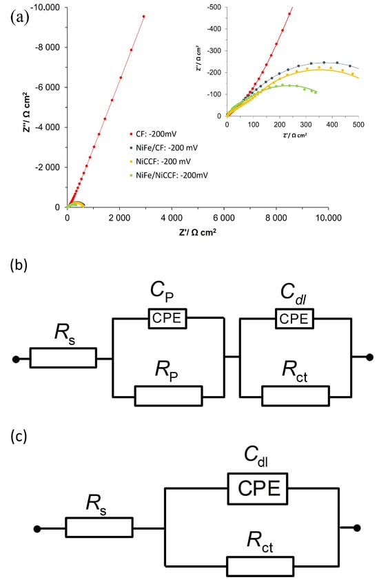
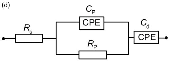
Figure 4.
(a) Electrochemical impedance Nyquist plots for the HER on CF, NiCCF, NiFe/CF, and NiFe/NiCCF electrode surfaces in contact with 0.1 M NaOH (at 293 K) for the potential of −200 mV vs. RHE; (b–d) equivalent circuits used to fit the above process, where Cp is the Faradaic pseudocapacitance, Rp is the Faradaic resistance and Cdl is the double-layer capacitance (both capacitance parameters are CPE: constant phase element−modified), jointly in series with an uncompensated solution resistance, Rs. The data derived from the equivalent circuits are represented by the solid lines.

Table 2.
Current densities for HER (η = 0.35 V) and OER (η = 0.57 V) recorded from CV curves.
2.2.2. A.c Impedance-HER
Figure 4a (and corresponding Figure S3) and Table 3 show the impedance spectroscopy results for modified electrodes and electrodes made of base materials, examined in 0.1 M NaOH. The electrochemical parameters, such as charge transfer resistance (Rct), porosity resistance for reaction intermediates (Rp), double-layer capacitance (Cdl), and pseudo-capacitance (Cp) parameters were obtained using two constant phase element (CPE)—modified Randles equivalent circuit model (Figure 4b–d). The impedance measurements of unmodified electrodes (CF) for potentials (from −100 to −600 mV vs. RHE) showed one depressed semicircle (associated with porosity response at high frequency) and linear part of the plot corresponding to CPE-modified capacitive response, recorded at medium and low frequencies. Then, between the potentials of −700 and −900 mV vs. RHE, a second semicircle corresponding to HER becomes visible on the EIS plot (medium and low frequencies). The Rp and Cp parameters presented for pure CF are mostly potentially independent as they could be associated with a response similar to the porous surface, simulated by the tow material [39]. In contrast, the Cdl parameter increased correspondingly from 83.8 to 214.3 µF cm−2 for the potentials of −100 and −900 mV. This phenomenon is probably associated with very poor catalytic properties and a strongly electrochemicaly non-uniform surface of the CF electrode; thus, increasing surface area becomes activated along with rising overpotential [39,40]. The Rct parameter (observed in the range of −700 to −900 mV) decreased from 19,156.8 to 1780.7 Ω cm2, respectively, which is characteristic of the kinetically controlled potential ranges.

Table 3.
Electrochemical parameters for the HER, obtained at as received CF, NiFe/CF, NiCCF, and NiFe/NiCCF electrodes in contact with 0.1 M NaOH supporting solution. The results obtained here were recorded by fitting the CPE-modified Randles equivalent circuit (the superscripts attached to potential value correspond to the model from Figure 4b–d) to the experimentally obtained impedance data (reproducibility usually below 10%, χ2 = 1.56 × 10⁻⁶ to 1.74 × 10⁻⁵).
The impedance Nyquist plots for the NiFe/CF electrodes showed two depressed semicircles in the potential range of −100 to −200 mV, where the high-frequency semicircle corresponds to the porosity of the electrode, and the low-frequency semicircle is related to the kinetics of the hydrogen evolution reaction. Notably, the presence of a semicircle connected to the HER process at lower overpotentials for modified electrodes suggests that these electrodes possess higher catalytic activity compared to the base CF electrode. The semicircle corresponding to Rp and Cp parameters was no longer visible for more negative potentials, as the CF tow material spread due to extended formation of H2 bubbles, thus losing its somewhat porous structure. The value of the Rct parameter was radically reduced—by about 160 times, as compared to the Rct values obtained for unmodified CF at the potential of −700 mV. Also, the NiFe modification caused the value of Cdl parameter to increase by 2.4 times for the same potential value. These results show that the presence of NiFe alloy significantly improves the CF material’s catalytic properties towards the HER. It is important to note that when focusing solely on the catalytic effect, independent of surface area changes, the enhancement of electrochemical performance is primarily driven by the catalytic properties of the NiFe alloy surface modifier (ca. 67 times, excluding the surface area augmentation).
Also, for the NiFe/CF electrode, increasing cathode overpotentials steadily caused the Rct parameter to be reduced from 1572.9 Ω cm2 to 120.7 Ω cm2 for the tested potential range. However, no significant changes were observed in the Cdl parameter values with rising cathode overpotentials. The fluctuation in the Cdl parameter values could be associated with the simultaneous blocking of the electrode surface by freshly formed H2 bubbles and “opening” of the CF tow material by these bubbles, thus leading to increased accessibility to the electrode’s surface area [29].
The EIS measurements for unmodified NiCCF resulted in two distinct semicircles in the potential range of −100 to −400 mV. The values of Rp and Cp parameters were independent of the applied potential and ranged between 130.1, 168.1 Ω cm2 and 91.3, and 161.7 µF cm−2, respectively. However, similarly to the EIS response for the NiFe/CF electrode, the Cp and Rp parameters were no longer visible at higher overpotentials. Similarly to the NiFe/CF catalyst material, the Rct parameter for the NiCCF electrode showed a decreasing trend with increasing overpotential, while the Cdl showed some unspecific fluctuations. Compared to the NiCCF electrode, the NiFe-modified CF catalyst exhibited considerably lower Rct parameter values, but primarily at significant cathodic overpotentials (Table 3).
The modification of the NiCCF electrode with NiFe alloy reduced the charge transfer resistance parameter by approximately 25% at the electrode potential of −100 mV. In contrast, the values of the Cdl parameter for the modified electrodes increased by approximately three times, as compared to unmodified ones. This suggests that the modification primarily influences the active surface area of the electrodes rather than its catalytic properties. Also, the behaviour of the Rct and the Cdl parameters for the NiFe-modified nickel-coated carbon fibre electrodes with rising overpotentials was similar to that observed for the unmodified ones; however, the recorded Cdl values for the former case were somewhat reduced, as compared to those derived for the latter ones.
The relationship of −log Rct and overpotential (η) for kinetically controlled reactions was selected here over the potential range −100 to −600 mV vs. RHE with 100 mV potential increments. The exchange current densities, j0, were calculated for the HER based on the Butler–Volmer equation and the relation between the j0 and the Rct parameter for the overpotential approaching 0 (see Equation (10) below) [26].
Such calculated j0 reached the values of 1.8 × 10⁻¹¹, 1.7 × 10⁻⁶, 1.4 × 10⁻⁶, and 1.7 × 10⁻⁶ A cm−2 for CF, NiFe/CF, NiCCF, and NiFe/NiCCF catalyst samples, respectively. The j0 values for the NiFe/CF, NiCCF, and NiFe/NiCCF electrodes showed comparable results, where the observed differences in the j0 values between the NiFe/CF and NiFe/NiCCF samples were indeed insignificant. This indicates that even with a lower catalyst (NiFe) loading, the samples achieved similar activities to that exhibited by the commercial product, which contains over four times as much Ni catalyst. The results presented in Table 4 (and corresponding Table S2) suggest that NiFe alloy deposited on carbon fibre is more cost-effective, compared to the same base material, but activated by noble metals. This conclusion can be drawn based on the comparable performance of NiFe to Pd- or Ru-modified carbon fibres (see Table 4 for details). Therefore, the utilisation of NiFe alloy provides a more economically viable alternative for diverse energy-related applications, including the oxidation of organic compounds, such as urea to serve as a more efficient and cost-effective anode option for the production of electrolytic hydrogen energy carrier, as compared to traditional water electrolysis strategies. Additionally, NiFe alloy could also serve as a superior active material for electrochemical supercapacitors. Its remarkable electrical conductivity and high surface area jointly contribute to efficient energy storage and charge/discharge characteristics, improving the supercapacitors’ overall performance and durability [41,42,43].

Table 4.
Exchange current densities for the HER (calculated based on the Butler–Volmer equation) in 0.1 M NaOH.
2.2.3. Tafel-HER
The Tafel polarisation plots recorded for CF, NiFe/CF, NiCCF, and NiFe/NiCCF electrodes are shown in Figure 5 (corresponding to Figure S4). The recorded cathodic slopes (bc) and exchange current densities for the HER are presented in Table 5. The potential range in which these parameters were measured was −50 to −200 mV for the NiFe/CF, NiCCF, and NiFe/NiCCF samples. However, as the onset of hydrogen evolution was observed at much more negative potentials on the CF sample, the potential range −700 to −900 mV/RHE was chosen for this electrode. This phenomenon was also reflected in the EIS results. The values of the Tafel-plot-derived j0 parameter are similar to those obtained by means of the Butler–Volmer equation-based method and demonstrate significantly improved catalytic properties after the NiFe electrode modification. Furthermore, these electrodes exhibited a more positive onset potential, as compared to the unmodified ones in Figure 6 (and related Figure S5). Furthermore, the obtained values of the exchange current density are comparable with the literature values presented in Table 4 and Table 5 (and corresponding Table S3).
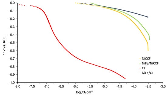
Figure 5.
Quasi-potentiostatic cathodic polarisation curves for the hydrogen evolution reaction (HER), obtained at CF, NiFe/CF, NiCCF, and NiFe/NiCCF electrodes in 0.1 M NaOH electrolyte. The polarisation curves were recorded at a scanning rate of 0.5 mVs− 1. The impedance-based solution resistance, iR, correction was also applied.
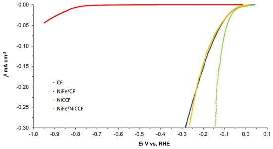
Figure 6.
Linear Sweep Voltammetry (LSV) curves of CF, NiFe/CF, NiCCF, and NiFe/NiCCF electrodes in 0.1 M NaOH solution, carried out with a scan rate of 0.5 mV s−1 for the HER (iR-corrected).
Then, for carbon-based electrodes, modified with 10 wt.% of NiFe alloy, the recorded j0 for the HER approached those typically derived for unmodified nickel electrodes [45]. Nevertheless, their catalytic efficiency towards the HER is about six times lower than that recorded for platinum electrodes. Interestingly, it is possible to find transition metal alloys that closely approach their HER parameters and the performance of platinum or even exhibit superior behaviour to the Pt (including one that is based on a NiFe catalyst [21,46]). This implies that the NiFe catalysts evaluated in this work may need to be optimised in order to enhance their HER performance.

Table 5.
HER kinetic parameters for the selected catalytic materials.
Table 5.
HER kinetic parameters for the selected catalytic materials.
| Material | bc [mV dec−1] | j0 [A cm−2] | Ref. | Electrolyte |
|---|---|---|---|---|
| CF | −108 | 3.1 × 10⁻¹³ | This work | 0.1 M NaOH |
| NiFe/CF | −62 | 1.7 × 10⁻⁶ | This work | 0.1 M NaOH |
| NiCCF | −63 | 1.5 × 10⁻⁶ | This work | 0.1 M NaOH |
| NiFe/NiCCF | −67 | 1.2 × 10⁻⁶ | This work | 0.1 M NaOH |
| NiFe/NiFoam | 157 | 1.7 × 10⁻⁵ | [46] | 1.0 M KOH |
| Ni | - | 2.3 × 10⁻⁶ | [45] | 0.1 M NaOH |
| Pt | −150 | 1.0 × 10⁻⁵ | [47] | 0.1 M NaOH |
| NiSn/Cu | −121 | 6.9 × 10⁻⁷ | [11] | 1.0 M KOH |
| NiCoSn/Cu | −122 | 1.2 × 10⁻⁵ | [11] | 1.0 M KOH |
| NiCu/C | −57 | 2.5 × 10⁻⁵ | [21] | 1.0 M KOH |
2.2.4. A.c. Impedance-OER
The impedance spectroscopy results for all examined electrode types are shown in Table 6. The OER behaviour presented in Figure 7 demonstrates that introducing modifications to the based carbon fibre electrodes resulted in considerably increasing the reactivity of the tested electrodes. The Rp and Cp parameters independently fluctuate in the span of the applied electrode potentials (also, see an explanation of the behaviour of these parameters in Section 2.2.2). The catalytic modification in the case of the CF electrode caused the recorded Rp value to decrease from 150.7 to 41.6 Ω cm2 (at the potential of 1400 mV), while the Cp value increased from 276.0 to 1982.0 µF cm−2 at the same electrode potential. On the other hand, the Rct and Cdl parameters’ values strongly depended on the applied potential. Specifically, the Rct parameter decreased along with increasing potential. In comparison, a decrease in the Cdl parameter upon the potential augmentation was slightly less pronounced (probably caused by a stronger blocking effect of O2 bubbles, compared to the tow “opening” effect, also see the explanation for the behaviour of this parameter given in Section 2.2.2). Additionally, the catalytic modification caused a decrease in the Rct parameter by approximately 147 times, while the Cdl parameter increased by approximately 13 times at the potential of 1600 mV. Similarly, as for the HER measurements, the catalytic properties of the CF electrodes were significantly enhanced by the presence of NiFe catalyst deposits (ca. 13 times) rather than an increase in the electrochemically active surface area of the composite material.

Table 6.
Electrochemical parameters for the OER, obtained at as received CF, NiFe/CF, NiCCF, and NiFe/NiCCF electrodes in contact with 0.1 M NaOH supporting solution. The results were recorded by fitting the CPE-modified Randles equivalent circuit (the superscripts attached to potential value correspond to the model from Figure 4b–d) to the experimentally obtained impedance data (reproducibility usually below 10%, χ2 = 1.31 × 10⁻⁶ to 5.37 × 10⁻⁶).
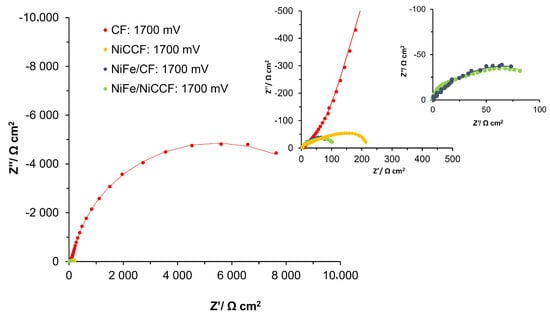
Figure 7.
Electrochemical Nyquist impedance plots for the OER on CF, NiCCF, NiFe/CF, and NiFe/NiCCF electrode surfaces in contact with 0.1 M NaOH solution (at 293 K) for the potential of 1700 mV vs. RHE.
In the case of the catalytic modifications based on the NiCCF electrode, there were no significant differences in the Rp and Cp parameters between the NiCCF and the NiFe/NiCCF samples. Although the values of these parameters were somewhat fluctuating regardless of the applied potential, their values generally decreased along with increasing electrode potential. This behaviour could most likely be attributed to a more pronounced “opening” effect of the tow material by freshly-formed O2 bubbles, again resulting in a loss of its somewhat porous nature.
Understandably, the Rct parameter for the NiCCF electrodes exhibited a significant decrease when modified with the NiFe alloy. At a potential of 1600 mV, the Rct value exhibited a reduction of approximately two times, indicating an improved catalytic effect of the NiFe alloy. However, it is noteworthy that the value of the Cdl parameter remained relatively unchanged at this potential, suggesting that the surface area of the NiCCF electrode did not experience significant alteration. These findings highlight the sole catalytic effect of the NiFe modification, independent of any notable changes in the surface area, as being a primary driver behind the observed enhancement of the electrochemical performance, observed at most examined potentials. For both types of electrodes, there is a noticeable decrease in the reaction resistance as the potential increases. Specifically, for the NiCCF electrodes, the resistance decreased from 1718.4 to 110.3 Ω cm2, while for the NiFe/NiCCF samples, it became reduced from 708.9 to 57.9 Ω cm2 in the potential range of 1500–1800 mV. The Cdl parameter, in this case, did not change significantly with the potential for the unmodified NiCCF electrodes, which is similar to the behaviour previously recorded for this parameter for the process of hydrogen evolution (see explanation in Section 2.2.2). However, for the NiFe/NiCCF sample, a radical decrease in the double-layer capacitance value with the rising electrode potential was observed, namely from 2339.0 to 168.7 µF cm−2 for the potential span 1500-1800 mV. This behaviour is significantly different from that of other electrodes, probably because the effect of blocking the carbon tow’s surface by the O2 bubbles was considerably more prominent than an enlargement of the electrochemically accessible surface area, obtained through the physical “opening” of the tow material. Furthermore, the effect of improved OER performance is also evident in the values of the j0 parameter obtained from the analysis of the Butler–Volmer equation, which came to 2.6 × 10⁻¹⁰, 9.4 × 10⁻⁸, 9.8 × 10⁻⁸ and 5.7 × 10⁻⁷ A cm−2 for the CF, NiFe/CF, NiCCF and NiFe/NiCCF samples, respectively.
2.2.5. Tafel-OER
Figure 8 (and corresponding Figure S7) shows the Tafel polarisation curves obtained for CF, NiFe/CF, NiCCF, and NiFe/NiCCF electrodes. The values of the anodic slope (ba) and the current density at an overpotential of 0.3 V (j(ŋ=0.3V)) for the OER are provided in Table 7 (and the corresponding Table S4). The potential range for which the linear part of the plots was determined is confined to the potential range: 1500–1600 mV. Figure 9 (and corresponding Figure S8) shows that the modified samples exhibited a lower OER onset potential than that of basic materials. The current densities and ba parameters obtained for the electrodes modified with NiFe were similar to those achieved by catalysts based on noble metals, such as platinum, ruthenium, and iridium. Additionally, it can be observed in Table 7 that apart from NiFe, there are various combinations of transition metals that can exhibit similar catalytic properties. This significantly increases the number of potential catalysts that could be utilised in this application. By exploring different metal combinations, there is a possibility to discover more efficient and cost-effective catalytic materials that meet specific requirements for the examined electrochemical processes.
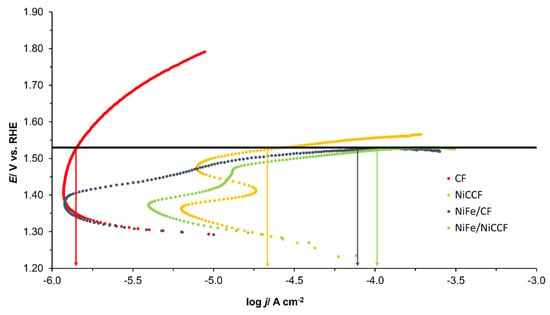
Figure 8.
Quasi-potentiostatic cathodic polarisation curves for the oxygen evolution reaction (OER) obtained for CF, NiFe/CF, NiCCF, and NiFe/NiCCF electrodes in 0.1 M NaOH solution. The polarisation curves were recorded at a scan rate of 0.5 mVs−1. The black line represents the overpotential of 300 mV. Arrows on the graph show the logarithm of the current density (log j) for each sample; the colour of the arrow matches the colour of the corresponding sample plot. The iR correction was applied to account for the solution resistance, based on the impedance measurements.
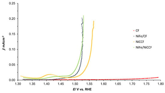
Figure 9.
Linear Sweep Voltammetry (LSV) curves of CF, NiFe/CF, NiCCF, and NiFe/NiCCF electrodes in 0.1 M NaOH solution, carried out with a scanning rate of 0.5 mV s−1 for OER (iR-corrected).
The current density values recorded on the examined materials at an anodic overpotential of 300 mV were similar to those achieved by bulk NiFe-LDH (Layered Double Hydroxide) materials [18]. While NiFe-modified CF and NiCCF electrodes did not exhibit as high current densities as certain other catalytic materials, such as IrO2 or CoP, they were simple to prepare and could readily be utilised for commercial purposes [17]. However, additional research may be necessary in order to optimize their catalytic capabilities, particularly with regard to the HER activity.
Please note that the respective overpotentials for all the examined fibre-based catalysts at the current density of 10 mA cm−2 are missing in Table 7 (also, see the results given in Figure 8 and Figure 9). However, it has to be noted that when the catalysts’ surface becomes readjusted to its electrochemically active part (see Table S4 in the supplementary information file), then the respected overpotential recorded at the current density of 10 mA cm−2 is as follows: 560, 290, 305, and 270 mV for CF, NiFe/CF, NiCCF, and NiFe/NiCCF, correspondingly. These results are in fact fully in line (or even somewhat superior to) with those presented in Table 7 (Table S4) for other NiFe-based catalysts.

Table 7.
OER kinetic parameters for the selected catalytic materials.
Table 7.
OER kinetic parameters for the selected catalytic materials.
| Material | Electrolyte | ba [mV dec−1] | j(ŋ=0.3V) [A cm−2] | η(j=10mAcm−2) [mV] | Ref. |
|---|---|---|---|---|---|
| CF | 0.1 M NaOH | 261 | 9.7 × 10⁻⁶ | - | This work |
| NiFe/CF | 0.1 M NaOH | 40 | 9.1 × 10⁻⁵ | - | This work |
| NiCCF | 0.1 M NaOH | 74 | 4.1 × 10⁻⁵ | - | This work |
| NiFe/NiCCF | 0.1 M NaOH | 60 | 1.7 × 10⁻⁴ | - | This work |
| RuO2/GC | 0.1 M NaOH | 44 | ~5.0 × 10⁻⁴ | - | [48] |
| Co3O4/GC | 0.1 M KOH | 69 | 5.9 × 10⁻⁶ | - | [49] |
| CoAl2O4/GC | 0.1 M KOH | 56 | 3.9 × 10⁻⁷ | - | [49] |
| ZnCo2O4/GC | 0.1 M KOH | 113 | 5.6 × 10⁻⁷ | - | [49] |
| Pt | 1.0 M KOH | 66 | 4.0 × 10⁻⁴ | - | [12] |
| Ni/Fe | 1.0 M NaOH | 38 | 3.3 × 10⁻⁵ | - | [16] |
| Co/Fe | 1.0 M NaOH | 46 | 1.2 × 10⁻⁵ | - | [16] |
| IrO2/GC | 1.0 M KOH | 76 | 3.9 × 10⁻³ | - | [17] |
| CoP/C | 1.0 M KOH | 71 | 5.0 × 10⁻³ | - | [17] |
| NiFe-LDH/GC | 1.0 M KOH | 35 | ~9.0 × 10⁻⁴ | 320 | [13] |
| Ni0.25Co0.75Ox | 1.0 M KOH | 36 | 7.9 × 10⁻⁵ | 377 | [14] |
| NiCo-LDH/GC | 1.0 M KOH | 41 | - | 335 | [18] |
| MnFe2O4/GC | 0.1 M KOH | 114 | - | 470 | [15] |
| NiFe2O4/GC | 0.1 M KOH | 98 | - | 440 | [15] |
In order to further assess the practical utilisation of our NiFe catalysts, we also conducted extended stability tests spanning 48 h. Figure S9 demonstrates a consistent electrochemical performance over time, with only minor variations over the recorded cell voltage for both HER and OER processes. The voltage jump observed in the graph is attributable to the temporary halt of the experiment for carrying out EIS measurements.
3. Materials and Methods
3.1. Solutions and Chemical Reagents
All solutions were prepared using a Spring 30 s ultra-pure water purification system from Hydrolab (with a resistivity of 18.2 MΩ cm). The 0.1 M NaOH supporting solution was prepared from sodium hydroxide pellets (99.9%, POCH, Gliwice, Poland). In addition, 0.5 M H2SO4 was made of sulphuric acid (98% Merck, Darmstadt, Germany) for charging a palladium reversible hydrogen electrode (RHE).
3.2. Electrodes and Electrochemical Cell
Electrochemical experiments were carried out in a typical electrochemical cell. The cell was made of Pyrex glass and contained three electrodes: carbon fibre (CF; Hexcel 12K AS4C, 12,000 single filaments of 7 μm diameter each) or nickel-coated carbon fibre (NiCCF; Toho-Tenax 12K50, 12,000 single filaments of about 7.5 μm diameter each and ca. 45 wt.% Ni)-based working electrode (WE), Pd RHE (Pd wire, 99.99% purity, 1.0 mm diameter, Sigma-Aldrich) as reference electrode (RE) and Pt counter electrode (CE; Pt wire, 99.99% purity, 1.0 mm diameter, Sigma-Aldrich). All electrodes were placed in separate compartments. In addition, before commencing experiments, atmospheric air was removed from the cell by bubbling with argon (Ar 5.0 grade, Eurogas Bombi, Dywity, Poland). Furthermore, argon gas flow was kept above the solutions throughout the experiments.
CF/NiCCF base electrodes were 1.5 cm long, with geometrical surface areas (GSA) of 39 cm2 for CF and 43 cm2 for NiCCF (based on the manufacturer-provided data). In the main manuscript, we reported electrochemical parameters based on the GSA of the CF or NiCCF base electrodes. However, in order to provide a more subtle understanding of the electrochemical behaviour, we also included additional results based on the electrochemically active surface area (ECSA) in the supplementary file (SF). The ECSA, estimated from the double-layer capacitance (Cdl), as shown in Figure S1, provides a more accurate measure of the active sites available for electrochemical reactions [50,51]. Nevertheless, it was observed that the parameters based on the ECSA seemed overly optimistic, possibly due to the specific conditions or assumptions made during ECSA estimation. Therefore, to maintain a conservative and broadly comparable approach, we have chosen to present the GSA-based results in the main manuscript. By reporting both the GSA- and ECSA-based parameters, we aim to give a comprehensive view of the electrochemical performance of our electrodes, thus allowing for a more in-depth interpretation and comparison of the obtained results. In order to remove a protective epoxy resin coating, the CF samples were heat-treated (at a low oxygen atmosphere for 4 h at 623 K), while the NiCCF samples were initially de-sized in acetone. Before running the experiments, the electrodes were oxidized in 0.1 M NaOH solution at an anodic current density of 0.3 mA cm−2 for 300 s. Catalyst electrodeposition was then performed according to the conditions and bath compositions presented in Table S5 (supplementary information file). Procedures for the preparation of laboratory equipment were as previously described in works by Pierożyński [26,27,29].
3.3. Experimental Methodology
All electrochemical measurements were performed at 293 K employing an AUTM 204 + FRA 32M Multi-Autolab potentiostat/galvanostat system. This work covers the employment of Tafel quasi-steady-state polarisation, electrochemical ac. impedance spectroscopy (EIS), and cycling voltammetry (CV) techniques. For EIS, the generator provided an output signal of a known amplitude of 5 mV, and the frequency range was typically swept between 1.0 × 10⁻⁵ and 0.5 × 10⁻¹ Hz. The instruments were controlled by Nova 2.1 software for Windows (Metrohm Autolab B.V., Opacz-Kolonia, Poland). Impedance data analysis was performed with ZView 2.9 software package (Windows, Scribner Associates, Inc. Berwyn, PA, USA), where the impedance spectra were fitted with a complex, non-linear, least-squares immittance fitting program, LEVM 6, written by J.R. Macdonald [52]. For CV measurements, three sweeps were carried out over the potential span of −1.0–1.8 V vs. RHE with a scanning rate of 50 mV s−1. Moreover, Tafel polarisation experiments (recorded at a scanning rate of 0.5 mV s−1) for the HER and OER experiments were conducted for all examined samples. Additionally, SEM/Energy-Dispersive X-ray (EDX) surface spectroscopy characterisation of all examined CF, NiCCF, and NiFe-modified CF, and NiCCF samples was carried out by means of Merlin FE-SEM microscope (Zeiss), equipped with Bruker XFlash 5010 EDX instrumentation (with 125 eV resolution).
4. Conclusions
In summary, the NiFe alloy deposited at a 10% by weight via NiFe electrodeposition on CF and NiCCF serves as a promising catalyst that could potentially be used as a material for practical electrodes in alkaline water electrolysers. The incorporation of the NiFe alloy into CF entities significantly reduced (160 times at a potential of −700 mV vs. RHE) the HER-associated charge transfer resistance along with nearly 150 times Rct reduction for the corresponding OER (at a potential of 1500 mV). Similarly, for NiCCF electrodes, the reduction in the charge transfer resistance was approximately 25% and 50% for the HER and OER, respectively. These findings highlight the effectiveness of the NiFe alloy in improving the electrochemical performance of both CF and NiCCF electrodes in alkaline water electrolysis applications.
Notably, when the recorded electrochemical parameters were normalised to the electrochemically active surface area (ECSA), the values appeared significantly higher than those obtained when normalised to the geometrical surface area (GSA). This could potentially point to an exceptionally high density of active sites on the electrode surface. However, given that these ECSA-normalised values seemed overly optimistic, we chose to employ a dual approach, reporting parameters based on both the GSA and ECSA data to offer a more balanced and comprehensive understanding of the catalyst performance.
Additionally, the recorded current density levels for both hydrogen and oxygen evolution reactions indicate that the NiFe alloy deposited on carbon-based materials could serve as a cost-effective and efficient alternative to noble metals and nickel-based materials that are currently used in commercial alkaline water electrolysers. Furthermore, the development of new catalysts based on transition metal alloys will enable further increase in the water electrolysis efficiency. However, in order to design a highly catalytic, Ni-based AWE stack system for optimised production of green hydrogen, further refining of catalyst composition along with additional electrochemistry work will be required.
Supplementary Materials
The following supporting information can be downloaded at: https://www.mdpi.com/article/10.3390/catal13121468/s1, Figures S1 to S9; Tables S1 to S5.
Author Contributions
Conceptualisation, M.K.; methodology, M.K.; formal analysis, M.K.; investigation, M.K.; data curation, M.K.; writing—original draft preparation, M.K.; writing—review and editing, T.M. and B.P.; supervision, T.M. and B.P. All authors have read and agreed to the published version of the manuscript.
Funding
This work has been primarily financed by the internal research grant no. 30.610.001-110, provided by The University of Warmia and Mazury in Olsztyn.
Data Availability Statement
Data supporting reported results will be available upon request.
Conflicts of Interest
The authors declare no conflict of interest.
References
- Yu, L.; Ren, Z. Systematic Study of the Influence of iR Compensation on Water Electrolysis. Mater. Today Phys. 2020, 14, 100253. [Google Scholar] [CrossRef]
- Yu, F.; Yu, L.; Mishra, I.K.; Yu, Y.; Ren, Z.F.; Zhou, H.Q. Recent Developments in Earth-Abundant and Non-Noble Electrocatalysts for Water Electrolysis. Mater. Today Phys. 2018, 7, 121–138. [Google Scholar] [CrossRef]
- Xiao, X.; Wang, X.; Li, B.; Jiang, X.; Zhang, Y.; Li, M.; Song, S.; Chen, S.; Wang, M.; Shen, Y.; et al. Regulating the Electronic Configuration of Ruthenium Nanoparticles via Coupling Cobalt Phosphide for Hydrogen Evolution in Alkaline Media. Mater. Today Phys. 2020, 12, 100182. [Google Scholar] [CrossRef]
- Chen, S.; Pei, C.; Gong, J. Insights into Interface Engineering in Steam Reforming Reactions for Hydrogen Production. Energy Environ. Sci. 2019, 12, 3473–3495. [Google Scholar] [CrossRef]
- Lagadec, M.F.; Grimaud, A. Water Electrolysers with Closed and Open Electrochemical Systems. Nat. Mater. 2020, 19, 1140–1150. [Google Scholar] [CrossRef]
- Da Silva Veras, T.; Mozer, T.S.; da Costa Rubim Messeder dos Santos, D.; da Silva César, A. Hydrogen: Trends, Production and Characterization of the Main Process Worldwide. Int. J. Hydrog. Energy 2017, 42, 2018–2033. [Google Scholar] [CrossRef]
- Yang, H.; Driess, M.; Menezes, P.W. Self-Supported Electrocatalysts for Practical Water Electrolysis. Adv. Energy Mater. 2021, 11, 2102074. [Google Scholar] [CrossRef]
- Shiva Kumar, S.; Himabindu, V. Hydrogen Production by PEM Water Electrolysis—A Review. Mater. Sci. Energy Technol. 2019, 2, 442–454. [Google Scholar] [CrossRef]
- Hall, D.E. Alkaline Water Electrolysis Anode Materials. J. Electrochem. Soc. 1985, 132, 41C. [Google Scholar] [CrossRef]
- Zhang, H.; Maijenburg, A.W.; Li, X.; Schweizer, S.L.; Wehrspohn, R.B. Bifunctional Heterostructured Transition Metal Phosphides for Efficient Electrochemical Water Splitting. Adv. Funct. Mater. 2020, 30, 2003261. [Google Scholar] [CrossRef]
- Vijayakumar, J.; Mohan, S.; Anand Kumar, S.; Suseendiran, S.R.; Pavithra, S. Electrodeposition of Ni–Co–Sn Alloy from Choline Chloride-Based Deep Eutectic Solvent and Characterization as Cathode for Hydrogen Evolution in Alkaline Solution. Int. J. Hydrog. Energy 2013, 38, 10208–10214. [Google Scholar] [CrossRef]
- Cui, X.; Zhang, B.; Zeng, C.; Guo, S. Elhe Oxygen Evolution Reaction on Passive Oxideoys toward Oxygen Evolution Reaction. MRS Commun. 2018, 8, 1230–1235. [Google Scholar] [CrossRef]
- Gong, M.; Li, Y.; Wang, H.; Liang, Y.; Wu, J.Z.; Zhou, J.; Wang, J.; Regier, T.; Wei, F.; Dai, H. An Advanced Ni–Fe Layered Double Hydroxide Electrocatalyst for Water Oxidation. J. Am. Chem. Soc. 2013, 135, 8452–8455. [Google Scholar] [CrossRef]
- Song, F.; Hu, X. Exfoliation of Layered Double Hydroxides for Enhanced Oxygen Evolution Catalysis. Nat. Commun. 2014, 5, 4477. [Google Scholar] [CrossRef]
- Li, M.; Xiong, Y.; Liu, X.; Bo, X.; Zhang, Y.; Han, C.; Guo, L. Facile Synthesis of Electrospun MFe2O4 (M = Co, Ni, Cu, Mn) Spinel Nanofibers with Excellent Electrocatalytic Properties for Oxygen Evolution and Hydrogen Peroxide Reduction. Nanoscale 2015, 7, 8920–8930. [Google Scholar] [CrossRef]
- Lyons, M.E.G.; Brandon, M.P. The Oxygen Evolution Reaction on Passive Oxide Covered Transition Metal Electrodes in Alkaline Solution. Part III—Iron. Int. J. Electrochem. Sci. 2008, 3, 1463–1503. [Google Scholar] [CrossRef]
- Chang, J.; Xiao, Y.; Xiao, M.; Ge, J.; Liu, C.; Xing, W. Surface Oxidized Cobalt-Phosphide Nanorods As an Advanced Oxygen Evolution Catalyst in Alkaline Solution. ACS Catal. 2015, 5, 6874–6878. [Google Scholar] [CrossRef]
- Suen, N.-T.; Hung, S.-F.; Quan, Q.; Zhang, N.; Xu, Y.-J.; Chen, H.M. Electrocatalysis for the Oxygen Evolution Reaction: Recent Development and Future Perspectives. Chem. Soc. Rev. 2017, 46, 337–365. [Google Scholar] [CrossRef]
- Zhang, K.; Zou, R. Advanced Transition Metal-Based OER Electrocatalysts: Current Status, Opportunities, and Challenges. Small 2021, 17, 2100129. [Google Scholar] [CrossRef]
- Zhang, X.-Y.; Yu, W.-L.; Zhao, J.; Dong, B.; Liu, C.-G.; Chai, Y.-M. Recent Development on Self-Supported Transition Metal-Based Catalysts for Water Electrolysis at Large Current Density. Appl. Mater. Today 2021, 22, 100913. [Google Scholar] [CrossRef]
- Gao, M.Y.; Yang, C.; Zhang, Q.B.; Yu, Y.W.; Hua, Y.X.; Li, Y.; Dong, P. Electrochemical Fabrication of Porous Ni-Cu Alloy Nanosheets with High Catalytic Activity for Hydrogen Evolution. Electrochim. Acta 2016, 215, 609–616. [Google Scholar] [CrossRef]
- Yu, X.; Wang, M.; Wang, Z.; Gong, X.; Guo, Z. 3D Multi-Structural Porous NiAg Films with Nanoarchitecture Walls: High Catalytic Activity and Stability for Hydrogen Evolution Reaction. Electrochim. Acta 2016, 211, 900–910. [Google Scholar] [CrossRef]
- Hota, P.; Bose, S.; Dinda, D.; Das, P.; Ghorai, U.K.; Bag, S.; Mondal, S.; Saha, S.K. Nickel-Doped Silver Sulfide: An Efficient Air-Stable Electrocatalyst for Hydrogen Evolution from Neutral Water. ACS Omega 2018, 3, 17070–17076. [Google Scholar] [CrossRef]
- Majee, R.; Kumar, A.; Das, T.; Chakraborty, S.; Bhattacharyya, S. Tweaking Nickel with Minimal Silver in a Heterogeneous Alloy of Decahedral Geometry to Deliver Platinum-like Hydrogen Evolution Activity. Angew. Chem. Int. Ed. 2020, 59, 2881–2889. [Google Scholar] [CrossRef]
- Pierozynski, B.; Smoczynski, L. Electrochemical Corrosion Behavior of Nickel-Coated Carbon Fiber Materials in Various Electrolytic Media. J. Electrochem. Soc. 2008, 155, C427. [Google Scholar] [CrossRef]
- Pierozynski, B.; Smoczynski, L. Kinetics of Hydrogen Evolution Reaction at Nickel-Coated Carbon Fiber Materials in 0.5 M H2SO4 and 0.1 M NaOH Solutions. J. Electrochem. Soc. 2009, 156, B1045. [Google Scholar] [CrossRef]
- Pierozynski, B. On the Hydrogen Evolution Reaction at Nickel-Coated Carbon Fibre in 30 Wt. % KOH Solution. Int. J. Electrochem. Sci. 2011, 6, 63–77. [Google Scholar] [CrossRef]
- Pierozynski, B.; Mikolajczyk, T.; Turemko, M.; Czerwosz, E.; Kozlowski, M. Hydrogen Evolution Reaction at Pd-Modified Carbon Fibre in 0.1 M NaOH. Int. J. Hydrog. Energy 2015, 40, 1795–1799. [Google Scholar] [CrossRef]
- Pierozynski, B. Hydrogen Evolution Reaction at Pd-Modified Carbon Fibre and Nickel-Coated Carbon Fibre Materials. Int. J. Hydrog. Energy 2013, 38, 7733–7740. [Google Scholar] [CrossRef]
- Doyle, R.; Godwin, I.; Brandon, M.; Lyons, M. Redox and Electrochemical Water Splitting Catalytic Properties of Hydrated Metal Oxide Modified Electrodes. Phys. Chem. Chem. Phys. PCCP 2013, 15, 13737–13783. [Google Scholar] [CrossRef]
- Díez-Pérez, I.; Gorostiza, P.; Sanz, F.; Müller, C. First Stages of Electrochemical Growth of the Passive Film on Iron. J. Electrochem. Soc. 2001, 148, B307. [Google Scholar] [CrossRef]
- Alsabet, M.; Grden, M.; Jerkiewicz, G. Electrochemical Growth of Surface Oxides on Nickel. Part 1: Formation of α-Ni(OH)2 in Relation to the Polarization Potential, Polarization Time, and Temperature. Electrocatalysis 2011, 2, 317–330. [Google Scholar] [CrossRef]
- Alsabet, M.; Grden, M.; Jerkiewicz, G. Electrochemical Growth of Surface Oxides on Nickel. Part 2: Formation of β-Ni(OH)2 and NiO in Relation to the Polarization Potential, Polarization Time, and Temperature. Electrocatalysis 2014, 5, 136–147. [Google Scholar] [CrossRef]
- Alsabet, M.; Grdeń, M.; Jerkiewicz, G. Electrochemical Growth of Surface Oxides on Nickel. Part 3: Formation of β-NiOOH in Relation to the Polarization Potential, Polarization Time, and Temperature. Electrocatalysis 2015, 6, 60–71. [Google Scholar] [CrossRef]
- Luo, H.; Su, H.; Dong, C.; Li, X. Passivation and Electrochemical Behavior of 316L Stainless Steel in Chlorinated Simulated Concrete Pore Solution. Appl. Surf. Sci. 2017, 400, 38–48. [Google Scholar] [CrossRef]
- Hahn, F.; Floner, D.; Beden, B.; Lamy, C. In Situ Investigation of the Behaviour of a Nickel Electrode in Alkaline Solution by Uv-Vis and Ir Reflectance Spectroscopies. Electrochim. Acta 1987, 32, 1631–1636. [Google Scholar] [CrossRef]
- Seyeux, A.; Maurice, V.; Klein, L.H.; Marcus, P. In Situ Scanning Tunnelling Microscopic Study of the Initial Stages of Growth and of the Structure of the Passive Film on Ni(111) in 1 mM NaOH(Aq). J. Solid State Electrochem. 2005, 9, 337–346. [Google Scholar] [CrossRef]
- van Drunen, J.; Barbosa, A.F.B.; Tremiliosi-Filho, G. The Formation of Surface Oxides on Nickel in Oxalate-Containing Alkaline Media. Electrocatalysis 2015, 6, 481–491. [Google Scholar] [CrossRef]
- Lasia, A. Electrochemical Impedance Spectroscopy and Its Applications; Springer: New York, NY, USA, 2014; ISBN 978-1-4614-8932-0. [Google Scholar]
- Mikolajczyk, T.; Pierozynski, B. Influence of Electrochemical Oxidation of Carbon Fibre on Cathodic Evolution of Hydrogen at Ru-Modified Carbon Fibre Material Studied in 0.1 M NaOH. Int. J. Electrochem. Sci. 2013, 8, 1182. [Google Scholar] [CrossRef]
- Yang, X.-L.; Lv, Y.-W.; Hu, J.; Zhao, J.-R.; Xu, G.-Y.; Hao, X.-Q.; Chen, P.; Yan, M.-Q. A Three-Dimensional Nanostructure of NiFe(OH)X Nanoparticles/Nickel Foam as an Efficient Electrocatalyst for Urea Oxidation. RSC Adv. 2021, 11, 17352–17359. [Google Scholar] [CrossRef]
- Babar, P.; Patil, K.; Lee, D.M.; Karade, V.; Gour, K.; Pawar, S.; Kim, J.H. Cost-Effective and Efficient Water and Urea Oxidation Catalysis Using Nickel-Iron Oxyhydroxide Nanosheets Synthesized by an Ultrafast Method. J. Colloid Interface Sci. 2021, 584, 760–769. [Google Scholar] [CrossRef]
- Ersoy Atalay, F.; Sener, M.; Kaya, H. High-Performance Supercapacitor Electrode Based on NiFe Nanowire Networks/PEDOT:PSS. Mater. Today Proc. 2020, 22, 172–179. [Google Scholar] [CrossRef]
- Pierożyński, B.; Mikołajczyk, T. Hydrogen Evolution Reaction at Ru-Modified Nickel-Coated Carbon Fibre in 0.1 M NaOH. Pol. J. Chem. Technol. 2015, 17, 18–22. [Google Scholar] [CrossRef]
- Zhou, Z.; Liu, Y.; Zhang, J.; Pang, H.; Zhu, G. Non-Precious Nickel-Based Catalysts for Hydrogen Oxidation Reaction in Alkaline Electrolyte. Electrochem. Commun. 2020, 121, 106871. [Google Scholar] [CrossRef]
- Wang, M.; Wang, J.-Q.; Xi, C.; Cheng, C.-Q.; Kuai, C.-G.; Zheng, X.-L.; Zhang, R.; Xie, Y.-M.; Dong, C.-K.; Chen, Y.-J.; et al. Valence-State Effect of Iridium Dopant in NiFe(OH)2 Catalyst for Hydrogen Evolution Reaction. Small 2021, 17, 2100203. [Google Scholar] [CrossRef]
- Zheng, Y.; Jiao, Y.; Vasileff, A.; Qiao, S.-Z. The Hydrogen Evolution Reaction in Alkaline Solution: From Theory, Single Crystal Models, to Practical Electrocatalysts. Angew. Chem. Int. Ed. 2018, 57, 7568–7579. [Google Scholar] [CrossRef]
- Reier, T.; Oezaslan, M.; Strasser, P. Electrocatalytic Oxygen Evolution Reaction (OER) on Ru, Ir, and Pt Catalysts: A Comparative Study of Nanoparticles and Bulk Materials. ACS Catal. 2012, 2, 1765–1772. [Google Scholar] [CrossRef]
- Wang, H.-Y.; Hung, S.-F.; Chen, H.-Y.; Chan, T.-S.; Chen, H.M.; Liu, B. In Operando Identification of Geometrical-Site-Dependent Water Oxidation Activity of Spinel Co3O4. Available online: https://pubs.acs.org/doi/pdf/10.1021/jacs.5b10525 (accessed on 12 June 2023).
- Connor, P.; Schuch, J.; Kaiser, B.; Jaegermann, W. The Determination of Electrochemical Active Surface Area and Specific Capacity Revisited for the System MnO x as an Oxygen Evolution Catalyst. Z. Für Phys. Chem. 2020, 234, 979–994. [Google Scholar] [CrossRef]
- Lasia, A. Mechanism and kinetics of the hydrogen evolution reaction. Int. J. Hydrog. Energy 2019, 44, 19484–19518. [Google Scholar] [CrossRef]
- Macdonald, J.R. Impedance Spectroscopy: Old Problems and New Developments. Electrochim. Acta 1990, 35, 1483–1492. [Google Scholar] [CrossRef]
Disclaimer/Publisher’s Note: The statements, opinions and data contained in all publications are solely those of the individual author(s) and contributor(s) and not of MDPI and/or the editor(s). MDPI and/or the editor(s) disclaim responsibility for any injury to people or property resulting from any ideas, methods, instructions or products referred to in the content. |
© 2023 by the authors. Licensee MDPI, Basel, Switzerland. This article is an open access article distributed under the terms and conditions of the Creative Commons Attribution (CC BY) license (https://creativecommons.org/licenses/by/4.0/).