Abstract
Proton exchange membrane (PEM) water electrolysis for hydrogen production has a high current density and overall efficiency, and is a very promising hydrogen production strategy. However, its application is limited by the high anodic overpotential for oxygen evolution and the instability of catalysts. Therefore, anodic catalysts with a high activity and durability under acidic conditions need further research. Herein, we first synthesized the key intermediate Ru@Ir core-shell structures by controlling nanocrystals, then loaded them onto a carbon support and calcined to obtain a RuO2@IrO2/C core-shell nanocatalyst with a size smaller than 5 nm, whose activity exceeded that of commercial RuO2 and commercial IrO2. After a 200 h stability test, the catalyst did not show significant performance degradation or structural degeneration. Finally, the prepared catalyst was assembled into a PEM electrolyzer showing the same results as the three-electrode tests, demonstrating its potential for practical applications and providing new insights for designing nanocatalysts suitable for industrialized PEM water electrolysis to produce hydrogen
1. Introduction
Proton exchange membrane (PEM) water electrolysis is regarded as an ideal strategy for efficiently generating green hydrogen. However, there are still significant challenges in developing oxygen evolution reaction (OER) catalysts that exhibit both a high activity and stability in acidic electrolytes [1,2,3,4,5,6]. At a low pH and high working potential of the anode, the application of most transition metals is limited [7,8,9,10,11]. Currently, iridium-based and ruthenium-based catalysts are considered the most promising materials. Generally, IrO2 exhibits a higher stability but poor activity under acidic conditions, which limits its large-scale application [12,13]. RuO2 shows a higher activity under acidic conditions. However, Ru4+ tends to be oxidized to RuO4, which dissolves in the electrolyte solution and leads to catalyst deactivation [14,15,16]. Therefore, it is urgent to develop catalysts that exhibit both a high activity and relatively high stability under acidic conditions.
To this end, researchers have synthesized various catalysts with different methods such as non-noble metal doping [9,17,18], alloying [19,20,21], morphology control [2,22,23], etc., to improve the performance and stability of catalysts. Ibchorkendorf et al. [12] prepared a corrosion-resistant metal oxide catalyst Ir0.1Ta0.9O2.45, which exhibited a good stability but unsatisfactory activity due to the low loading of active substances. The low-ruthenium oxide material (Cr0.6Ru0.4O2) prepared by Lin et al. [24] showed a significant oxygen evolution performance in acidic conditions. However, it only maintained stability for 10 h under 10 mA/cm2 constant current conditions in a 0.5 M H2SO4 solution. Therefore, when selecting OER catalysts in acidic electrolytes, we need to strike a balance between stability and activity and adopt suitable methods to effectively combine the two elements. Core-shell nanocatalysts are a promising type of material essentially consisting of atomic metal monolayers supported on metal core substrates. They can effectively induce charge redistribution of outer layer active sites through strong electronic interactions between the interior and exterior components [25,26]. The synergistic effect of the ligand effect and strain effect has been proven to enhance catalytic activity in extensive applications [27,28,29]. Therefore, the Ru@Ir core-shell nanostructures have tremendous potential to improve catalytic performance. Yang et al. [30] prepared an IrRux@Ir core-shell structure catalyst through the traditional sol-gel method. The overpotential at a current density of 10 mA cm−2 was 288 mV, and it was only stable for 24 h. Wang et al. [31] developed an Ir0.95Ru0.05/Ti self-supporting electrode with a good water electrolysis activity, but the stability is not ideal under long-term operation. Song et al. [32] prepared a highly active IrRu alloy through a simple co-precipitation method, but it was unable to operate stably for a long time and could only operate stably for 10 h at a current density of 10 mA cm−2. However, due to various influencing factors and complex modulation mechanisms [11], the application of Ru@Ir catalysts in acidic OER is still very limited.
In this work, we report a two-step strategy to synthesize low-size core-shell nanoparticles by first synthesizing the key intermediate Ru@Ir via nanocrystalline modulation, and then loading it onto carbon carriers and calcining it to obtain RuO2@IrO2/C core-shell-structured catalysts with the average size of the particles being only 3.44 nm. This catalyst demonstrated a good OER activity and stability, requiring an overpotential of only 257 mV to achieve a current density of 10 mA/cm2, and maintaining a good stability for 200 h. X-ray photoelectron spectroscopy (XPS) was utilized to analyze the changes in surface properties, X-ray diffraction (XRD) to examine the crystal structure, and high-angle annular dark-field scanning transmission electron microscopy (HAADF-STEM) along with high-resolution transmission electron microscopy (HRTEM) to characterize the particle size and morphology. Finally, the prepared catalysts were tested in PEM electrolyzer cells, providing valuable insights into the design of anodic catalysts suitable for industrial applications of PEM water electrolysis.
2. Results and Discussion
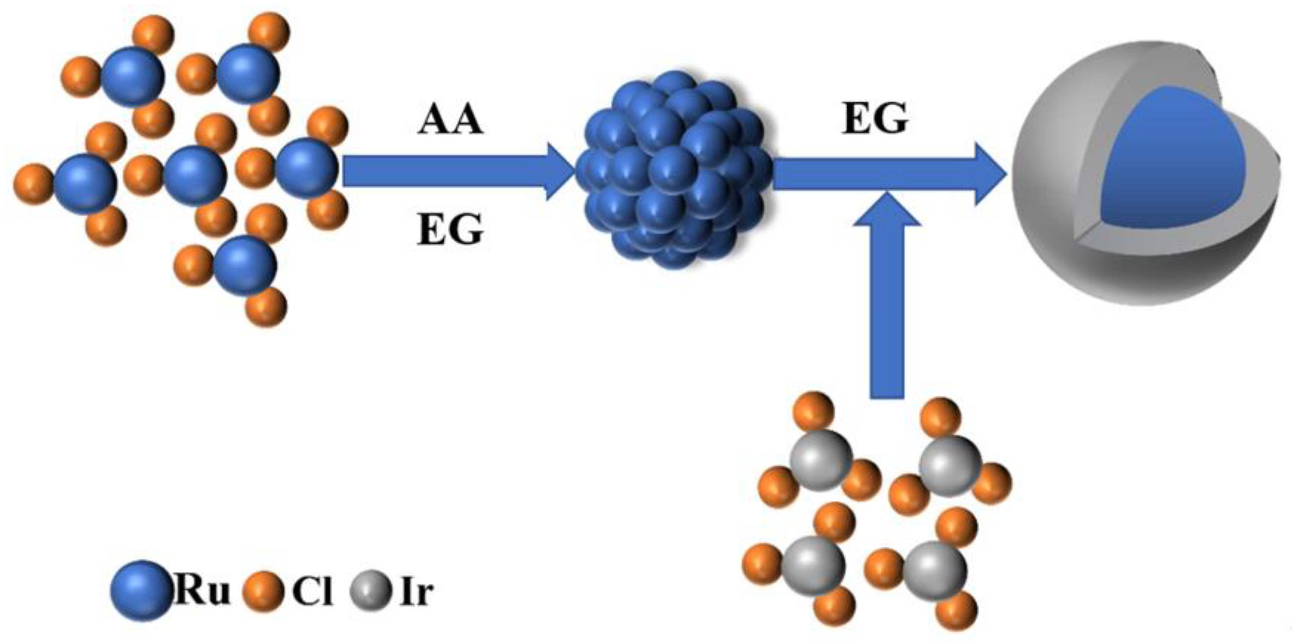
To prepare the RuO2@IrO2/C core-shell catalyst, we developed a two-step synthesis process. First, ascorbic acid (AA, the same below) was used as a weak reducing agent to control the growth of Ru cores, and then Ir precursors were added to synthesize the key intermediate Ru@Ir core-shell nanoparticles. Figure 1 shows the flow of Ru@Ir core-shell nanoparticles intermediates’ regulated synthesis. Finally, the Ru@Ir core-shell structure nanoparticles are loaded onto the carbon support and calcined to obtain a small-sized RuO2@IrO2/C nano-core-shell structure catalyst. The type of carbon carrier used is EC600, which has superconducting properties and excellent stability. The addition of AA changed the reduction rate and promoted the growth of Ru core particles. The optimized AA addition amount was 20 mg (Figures S1 and S2), and the molar ratio of Ru:Ir was 2:1 (Figures S3–S5), which was determined through rigorous performance optimization.
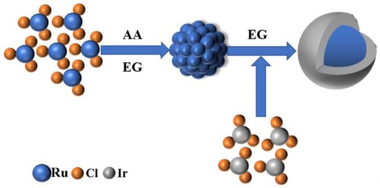
Figure 1.
Ru@Ir Schematic diagram of intermediate regulation synthesis.
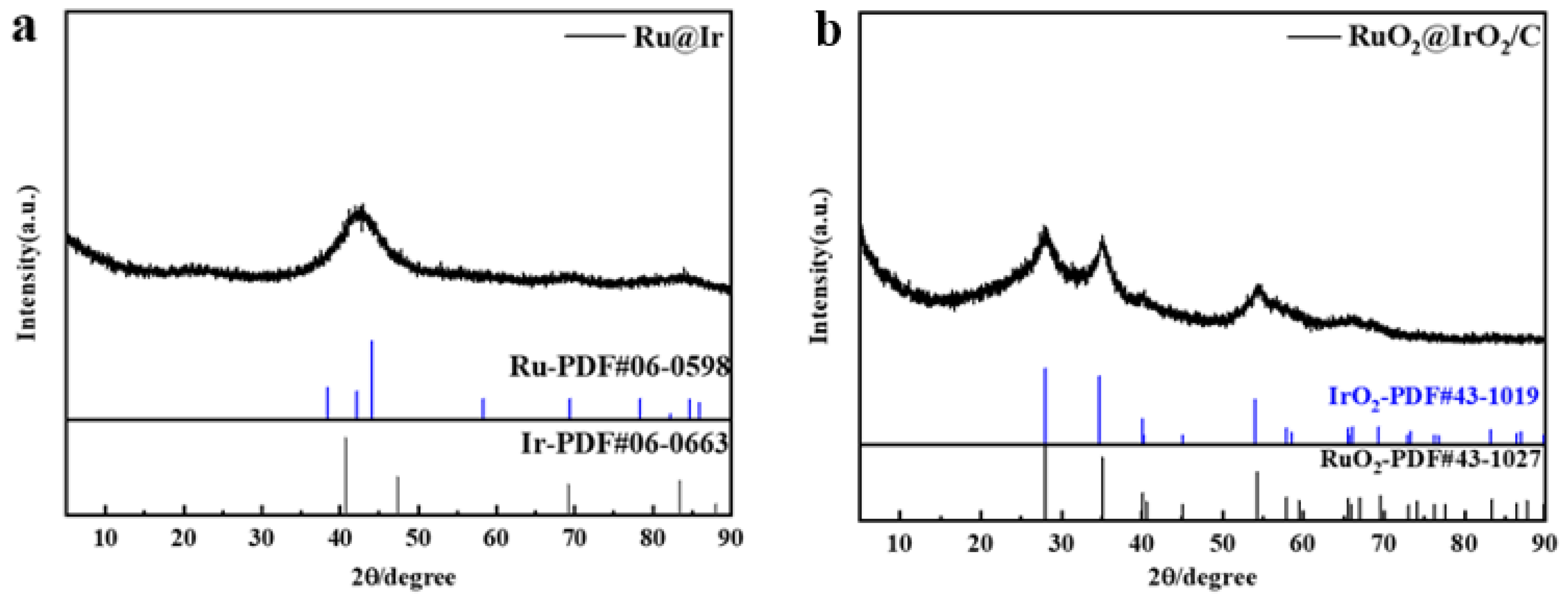
From the X-ray diffraction (XRD) of Ru@Ir in Figure 2a, it can be seen that the catalyst has the highest sharp-shaped diffraction peak at 42.5°, and it corresponds to the standard cards Ir (PDF#06-0598) and Ru (PDF#06-0663), which are located in the middle of the standard cards Ir (111) and Ru (101), which indicates the formation of the core-shell structure of Ir and Ru. The sharpness of the diffraction peaks indicates that the catalyst is polycrystalline. The atomic structure of the catalyst can be further recognized by high-resolution transmission electron microscopy (HRTEM), and the HRTEM images clearly show that the catalyst is polycrystalline, and focusing on individual nanoparticles reveals obvious lattice fringes with a lattice stripe spacing of 2.21 Å, 2.07 Å (Figure 3d,e), which corresponds to the (111) crystallographic plane of Ir and the (101) crystallographic plane of Ru, respectively, and is in good agreement with the XRD results. Meanwhile, the corresponding energy dispersive spectroscopy (EDS) elemental maps clearly reveal the co-existence of Ru and Ir with a good dispersion on individual nanoparticles (Figure 3f). The EDX line scan of Figure 3c further demonstrates the core-shell structure of the catalyst, with the edge portion of the nanoparticles containing significantly more Ir than Ru, in conjunction with other researchers’ work [33,34]; this proves that the Ru@Ir core-shell structure has formed. Ru@Ir core-shell nanoparticles oxidized to RuO2@IrO2/C by calcination at 300 °C for 1 h in an air atmosphere showed characteristic peaks of rutile (Figure 2b). Transmission electron microscopy (TEM) clearly shows that the RuO2@IrO2 nanoparticles are uniform in size, with an average diameter of ~3.44 nm (Figure 3b). This ultrafine nanoparticle is inherited from its precursor (i.e., Ru@Ir). The average size of the nanoparticles is only 1.93 nm (Figure 3a). The carbon support plays a very important role in preventing the particles from aggregating and becoming larger during the calcination of Ru@Ir into the RuO2@IrO2/C core-shell structure catalyst.
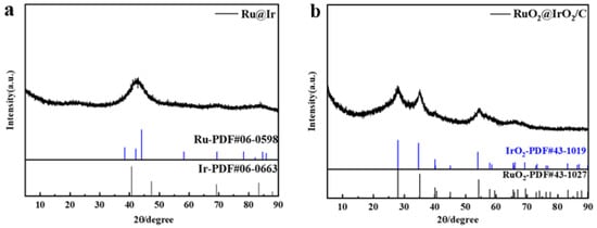
Figure 2.
XRD patterns of (a) Ru@Ir and (b) RuO2@IrO2/C.
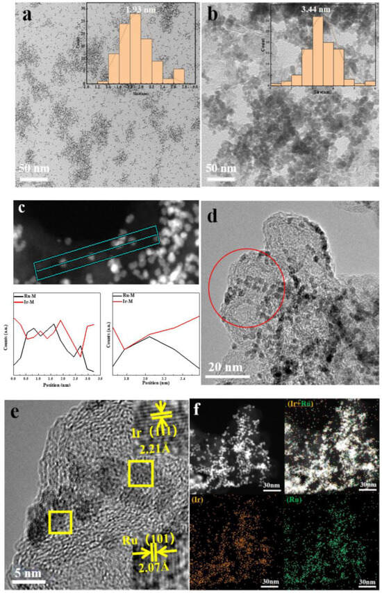
Figure 3.
Characterization of catalytic materials (a) TEM image of Ru@Ir/C; (b) TEM image of RuO2@IrO2/C; (c) EDX spectrum of Ru@Ir/C,the straight line in the figure is the line scan position; (d,e) HRTEM images of Ru@Ir/C, picture e is a partial enlarged view of the circle position in picture d, partial enlargement of the boxed area in Figure e; (f) Elemental mapping of Ru@Ir/C.
The HRTEM image of RuO2@IrO2/C shows the lattice stripes of the catalyst (Figure 4a). Focusing on a single core-shell structure nanoparticle, the lattice stripe spacing is 2.58 Å, which corresponds to the (101) crystal plane of IrO2. There is no RuO2 lattice. It can be inferred that the generated IrO2 shell has surrounded the RuO2 core, resulting in RuO2. The lattice is not displayed. The EDS pattern of the catalyst in Figure 4b shows the co-existence of the two elements and the formation of the core-shell structure, thus proving the inference of the previous step. The EDX line scan of RuO2@IrO2/C (Figure 4c,d) shows that the content of Ir in the edge portion of the nanoparticles is significantly more than that of Ru, which proves the formation of the RuO2@IrO2/C core-shell structure.
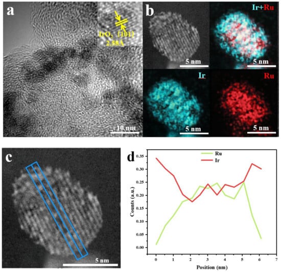
Figure 4.
Characterization of catalytic materials (a) HRTEM image of RuO2@IrO2/C; (b) Elemental mapping of RuO2@IrO2/C; (c) EDX spectrum of RuO2@IrO2/C, the blue line represents the position of the line scan; (d) the content of Ir and Ru
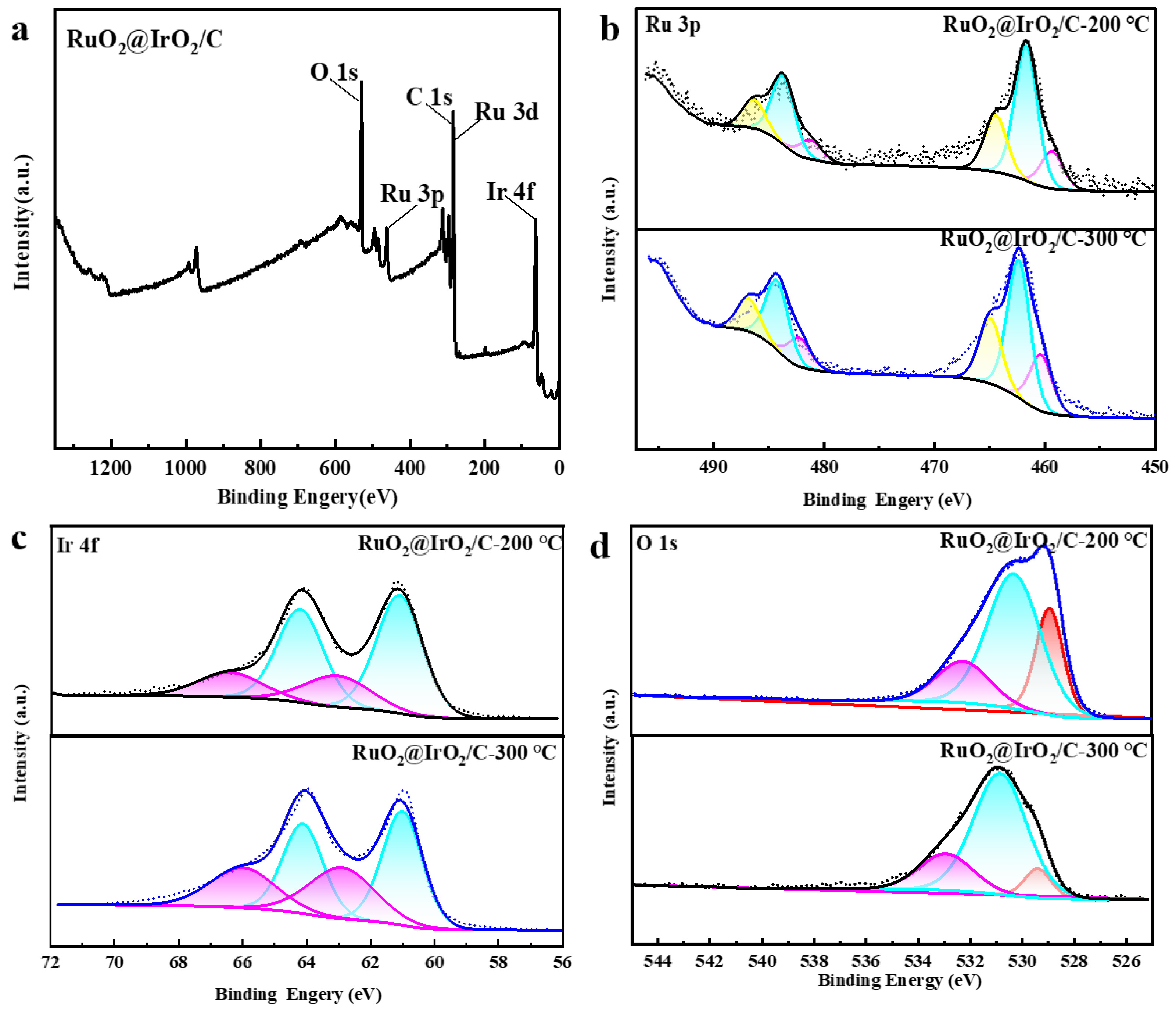
To further verify, X-ray photoelectron spectroscopy (XPS) was used to analyze the surface electronic structure. The XPS spectrum of Ru@Ir (Figure S2) shows the Ru 3p fine spectrum has three doublets, centered at 458.8 eV, 461.58, and 464.6 eV, belonging to the metallic Ru, Ru3+, and Ru4+, respectively, indicating the addition of AA makes Ru@Ir the Ru atom which has a lower valence state. The Ir 4f spectrum has two split peaks, 4f7/2 and 4f5/2, corresponding to two pairs of peaks at 61.2 and 64.2 eV, 63.2 and 66.3 eV, attributable to the Ir0+ and Ir4+ oxidation states. In contrast, Ru@Ir-0 mg AA shows three doublets with significantly lower binding energies, indicating AA induces higher oxidation states of Ir in Ru@Ir (Figure S2). The binding energy changes in Ir and Ru demonstrate strong electronic interactions between the Ir-rich shell layer and the Ru core. From the full spectrum of RuO2@IrO2/C (Figure 5a), the presence of Ir, Ru, O, and C elements indicates the successful synthesis of RuO2@IrO2/C. Figure 5b shows the Ru 3p fine spectrum of RuO2@IrO2/C after calcination at 300 °C, displaying three doublets centered at 460.5 eV, 462.4 eV, and 464.9 eV, attributable to the metallic Ru, Ru3+, and Ru4+ species, respectively. In contrast, RuO2@IrO2/C after 200 °C calcination shows lower binding energy split peaks, indicating the 200 °C calcination results in lower oxidation states of the Ru and Ir elements without being fully oxidized. It is also found that with increasing calcination temperature, the Ru4+/Ru peak area ratio gradually increases, reflecting the gradual increase in Ru4+ content. From Figure 5c, the Ir 4f XPS spectrum of Ru@Ir/C shows two peaks corresponding to the 4f7/2 and 4f5/2 states, with a separation of 3 eV. The double peaks at 61.1/64.1 eV and 62.9/66.1 eV belong to the Ir0 and Ir4+ species, respectively, indicating the co-existence of mixed valence states of Ir. With increasing calcination temperature, the area ratio of Ir4+/Ir0 increases, reflecting the enrichment of Ir4+ as the primary active species to promote OER activity [35]. Meanwhile, Figure 5d shows that when the calcination temperature is 300 °C, the area of the lattice oxygen peak at 529.2 eV in the O 1s spectrum is smaller than that at 200 °C. It shows that as the calcination temperature increases, the lattice oxygen participating in the reaction decreases, and the active sites are transferred to oxygen vacancies. The maximum amount of oxygen vacancies is generated when the calcination temperature is 300 °C, thus increasing the number of active sites.
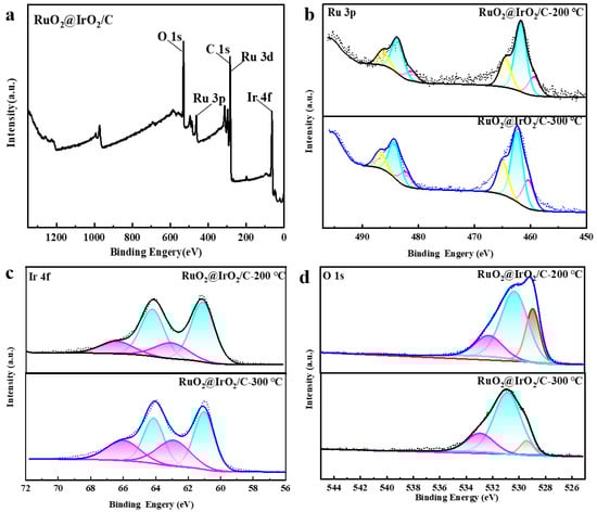
Figure 5.
XPS images of Ru@Ir/C after AA regulation, different colored lines and the areas below represent different peaks. (a) Full spectrum; (b) Ru 3p fine spectrum; (c) Ir 4f fine spectrum; (d) O 1s fine spectrum.
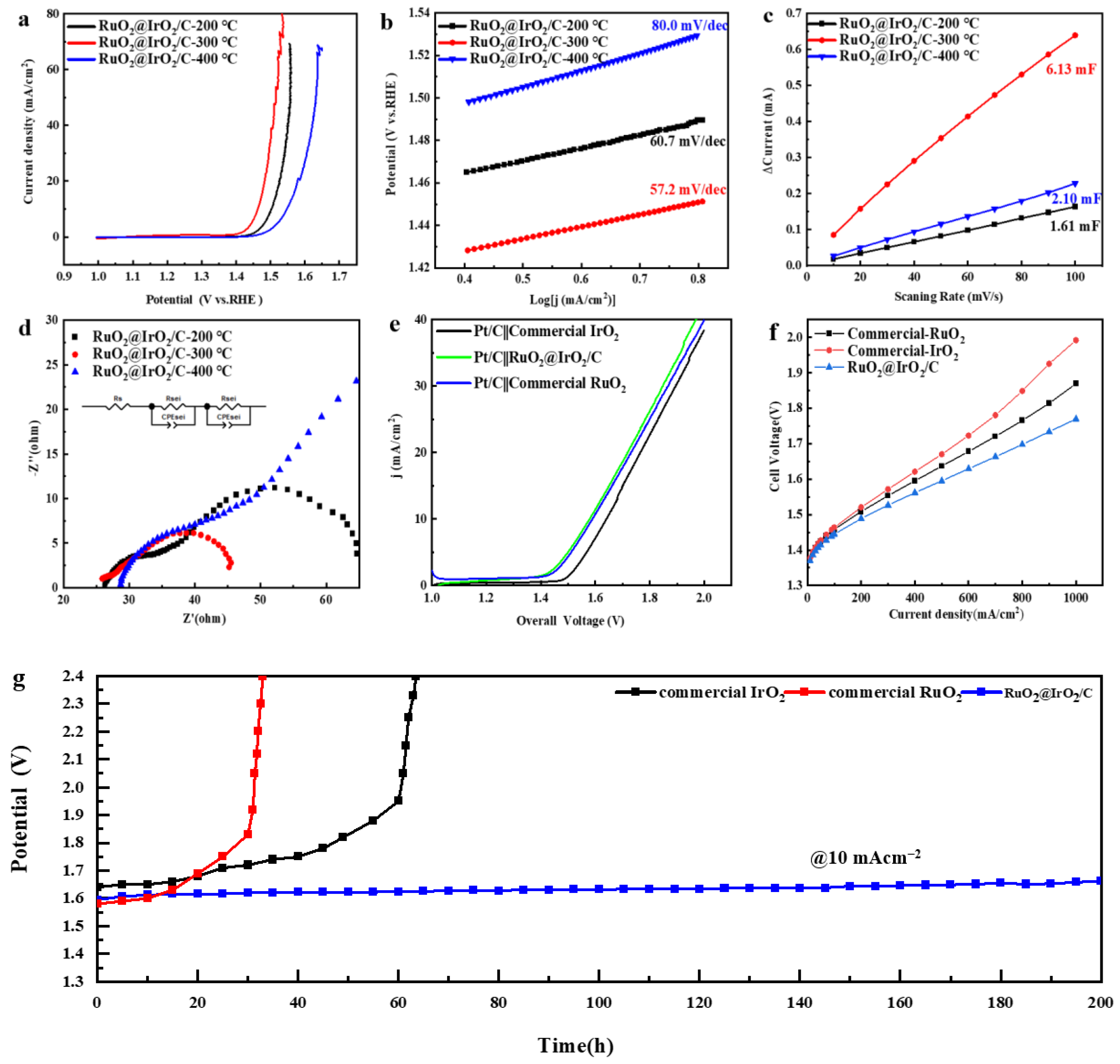
In order to test the catalytic performance of core-shell structured catalysts, performance testing of RuO2@IrO2/C catalysts with different calcination temperatures in a 0.1 M HClO4 solution saturated with O2 OER was conducted. Figure 6a shows the LSV curves of the catalysts at different calcination temperatures. The overpotential of catalysts at 10 mA/cm2 decreases and then increases as the calcination temperature increases, and it has the lowest overpotential of 257 mv at 300 °C, which is much lower than that of the commercial IrO2 (350 mV) and commercial RuO2 (300 mV). To further elucidate the activity origin of the catalyst, the corresponding Tafel plots were fitted from the LSV curves to reflect the reaction kinetics of the catalysts. Figure 6b shows that the Tafel slope of the catalyst with a calcination temperature of 300 °C is 57.2 mV/dec, which is lower than that of the catalysts with other calcination temperatures, indicating the kinetic reaction rate of the catalyst with a calcination temperature of 300 °C is the fastest, and the corresponding catalytic activity is also the strongest. To calculate the electrochemical active surface area (ECSA) [36] of the catalysts, the double-layer capacitance of the catalysts was measured by cyclic voltammetry (CV) in the non-Faradaic region (Figure S8). Figure 6c shows the double-layer capacitance (Cdl) of the catalyst at different calcination temperatures. It can be seen that the Cdl value of the catalyst at 300 °C is 6.13 mF, which is four times higher than that at 200 °C (1.61 mF) and three times higher than that at 400 °C (2.1 mF). Since ECSA is proportional to Cdl, it can be seen that the catalyst with a calcination temperature of 300 °C has the highest electrochemical specific surface area. This fully demonstrates that when the calcination temperature is 300 °C, the RuO2@IrO2/C catalyst has the largest electrochemical reaction active area and can effectively expose more active sites, resulting in the oxygen evolution reaction proceeding more rapidly. From the Nyquist plot obtained by fitting the electrochemical impedance spectroscopy (EIS) of the catalyst at 1.45 V (Figure 6d), it can be seen that the RuO2@IrO2/C catalyst obtained by calcination at 300 °C has a smaller charge transfer resistance (Table S1).
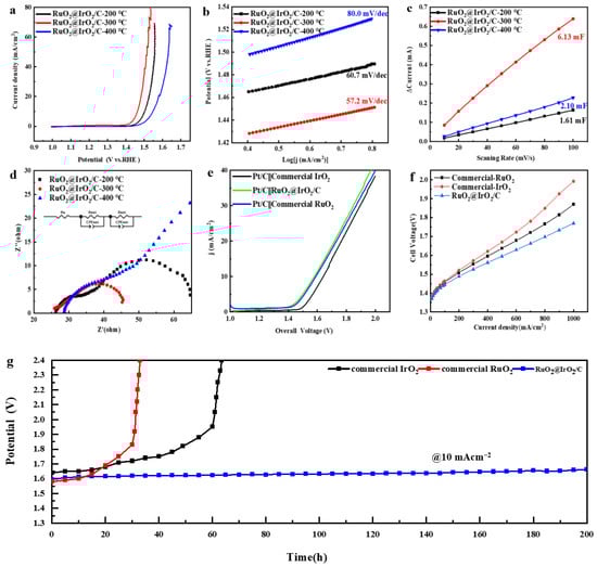
Figure 6.
OER performance of RuO2@IrO2/C. (a,b) LSV curves and Tafel slopes of RuO2@IrO2/C calcined at different temperatures, respectively. (c) Cdl diagram derived from CV curves. (d) Nyquist plots obtained from EIS of RuO2@IrO2/C calcined at different temperatures. (e) Full water splitting polarization curves of commercial IrO2, commercial RuO2, and RuO2@IrO2/C calcined at 300 °C. (f) PEM electrolyzer performance with 50% Pt/C as the cathode, commercial IrO2, commercial RuO2, and RuO2@IrO2/C calcined at 300 °C as the anode. (g) Chronopotentiometry of RuO2@IrO2/C, commercial IrO2, and commercial RuO2 at 10 mA/cm2.
The electrochemical stability of RuO2@IrO2/C was measured using chronopotentiometry. The cathode and anode catalysts (50%Pt/C was the cathode, RuO2@IrO2/C was the anode) were drop-coated on carbon paper, and the stability and water electrolysis performance tests were performed in a two-electrode system. The electrolysis water polarization curve test was conducted on a two-electrode system with Pt/C as the cathode, RuO2@IrO2/C, commercial RuO2, and IrO2 as the anode, respectively (Figure 6e). At a current density of 10 mA/cm2, the overpotential of RuO2@IrO2/C is 1.589 V, which is close to the overpotential of commercial RuO2 (1.58 V) and lower than the overpotential of commercial IrO2 (1.641 V) (Figure S6). At a constant current density of 10 mA/cm2, there was no obvious change in voltage after 200 h of testing (Figure 6g), and the subsequent increase in potential may be due to the shedding of the catalyst during the testing process, or it may be generated during the electrolysis process as the bubbles encounter difficulty in coming off. The catalyst was then subjected to a TEM test after the stability test, and the characterization graph (Figure S7) shows that the average particle size of the catalyst is about 3.52 nm, which is basically the same as the particle size before the test (3.44 nm). The morphology of the carbon support did not change significantly, and the RuO2@IrO2 particles on the carbon support did not show obvious expansion and agglomeration. If the carbon support is corroded, the size of the RuO2@IrO2 particles on the carbon support will increase and agglomerate to a certain extent. Then, the XRD test was conducted on the catalyst after the stability test (Figure S11), and the crystal phase of the catalyst did not change after the stability test, which further proved the good stability of the catalyst. The activity and stability of the RuO2@IrO2/C catalyst are the best compared with other reported acidic OER catalysts (Table 1).

Table 1.
The comparison of OER performance of RuO2@IrO2/C with recently reported electrocatalysts in acid media.
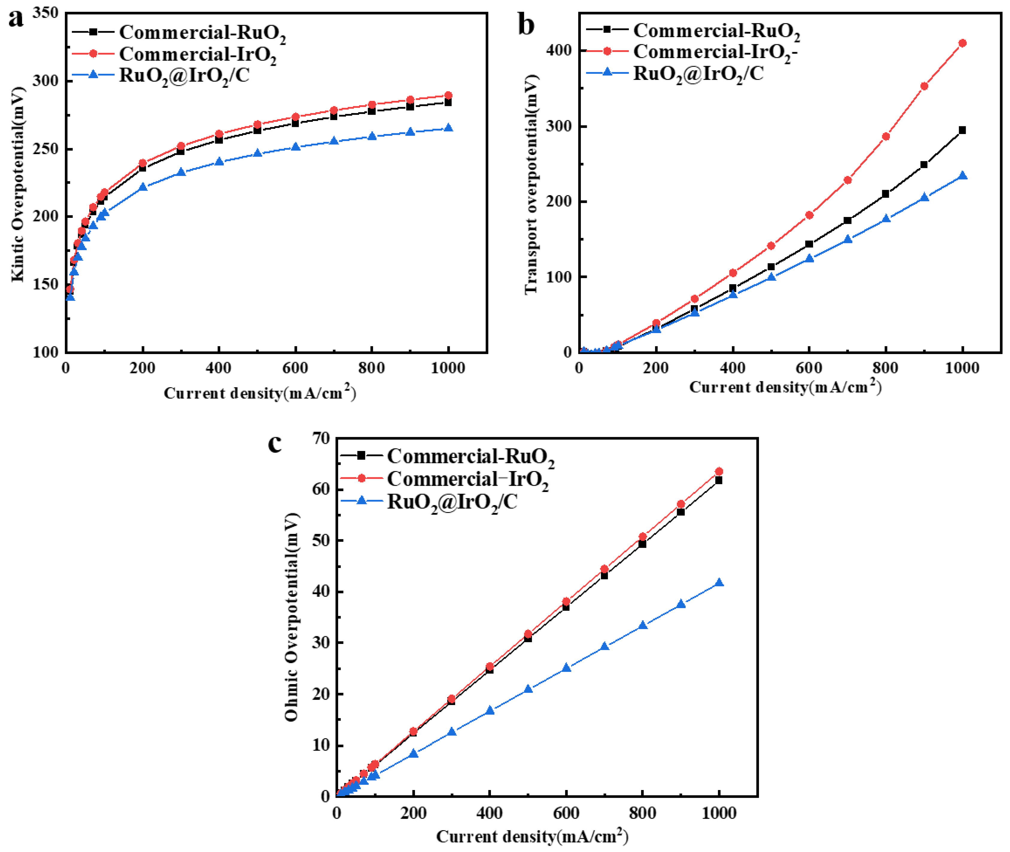
In order to test the performance of the catalyst in a PEM electrolyzer (Figures S9 and S10), a membrane electrode assembly (MEA) with RuO2@IrO2/C as the anode and 50%Pt/C as the cathode was assembled. The polarization curves were recorded at 60 °C, as shown in Figure 6f, and the voltage required for RuO2@IrO2/C at the same current density was less than that of commercial IrO2 and RuO2. Kinetic overpotential (Figure 7a), mass transport overpotential (Figure 7b), and ohmic overpotential (Figure 7c) together constitute the voltage required in the process of the electrolysis of water. The direct theoretical basis for the kinetic overpotential is Tafel, which is the actual starting voltage value at which the oxygen evolution reaction of electrolyzed water occurs. It is positively correlated with the number of active sites on the catalyst surface. From Figure 6a, it can be seen that the catalyst has good intrinsic properties. Consistent with the three-electrode test results. Figure 6b shows that the mass transport overpotential is lower than commercial IrO2 and commercial RuO2 catalysts, indicating that the RuO2@IrO2/C catalyst requires less external voltage to overcome gas–liquid transport (bubbles, electrolyte concentration). The ohmic overpotential is caused by the voltage increase caused by the resistance of the catalyst and diaphragm, and only accounts for a small part of the total voltage. It can be seen from Figure 6c that the RuO2@IrO2/C catalyst is the best compared with commercial IrO2 and commercial RuO2. The membrane electrodes with 50% Pt/C at the cathode and RuO2@IrO2/C, commercial IrO2, and commercial RuO2 at the anode were subsequently tested for kinetic overpotentials, mass transport overpotentials, and ohmic overpotentials on a PEM single electrolyzer. It was found that at the same current density, the kinetic overpotential, mass transport overpotential, and ohmic overpotential of RuO2@IrO2/C are all smaller than commercial IrO2 and RuO2, proving that using RuO2@IrO2/C as the anode of a PEM electrolyzer can effectively reduce energy loss.
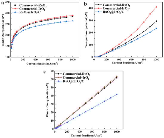
Figure 7.
Electrolyzer performance of RuO2@IrO2. (a) Kinetic overpotential. (b) Mass transport overpotential. (c) Ohmic overpotential.
3. Conclusions
In summary, we prepared a RuO2@IrO2/C core-shell structured catalyst by controlling the catalyst particle size and the catalyst structure. The catalyst showed an excellent activity and durability in 0.1 M HClO4, with an overpotential of only 257 mV at a current density of 10 mA/cm2, and it could be operated stably for 200 h at this current density without significant performance degradation. This is because the IrO2 shell can produce strong electronic interactions with the RuO2 core, thereby improving the activity of the catalytic material, and the presence of the IrO2 shell slows down the dissolution rate of the RuO2 core to maintain the better stability of the catalyst. Finally, the catalyst was tested in a PEM electrolyzer. Compared with commercial IrO2 and commercial RuO2, it has a better durability and water electrolysis activity, showing the advantages and potential value of this core-shell structure catalyst in industrial applications.
4. Experimental Section
4.1. Materials
Ruthenium chloride hydrate (RuCl3·xH2O, 99.9%), Iridium chloride (IrCl3, 99.9%), sodium hydroxide (NaOH, 99.9%), Ascorbic acid (C6H8O6), and polyvinylpyrrolidone (PVP, K23–27) were obtained from Aladdin Shanghai, China. Glycol (HOCH2CH2OH, 99.5%) from McLean Shanghai, China. Ethyl alcohol (CH3CH2OH, 99.9%), acetone (C3H6O, 99.0%), and carbon black (EC600) were purchased from Sinopharm, Shanghai, China. Pt/C (47.5%, mass fraction, Pt) was obtained from Sinopharm. All chemicals were used as received without any further purification. The distilled water (10–15 MΩ·cm) used throughout all experiments was purified through a Millipore system.
4.2. Preparation of Ru@Ir Nano Intermediates
AA-regulated synthesis of Ru@Ir: 200 mg of PVP and 40 mg of RuCl3, as well as 20 mg of AA, were added to 14 mL of ethylene glycol and ultrasonically dissolved for 30 min until the particles were completely dissolved. Then, it was transferred to a pressure-bearing tube and heated to 180 °C for a constant temperature reaction of 3 h to obtain the Ru core. After natural cooling, it was transferred to a three-necked flask, heated under an N2 atmosphere, and an ethylene glycol solution dissolving IrCl3 was added dropwise at a uniform speed. After refluxing until the temperature rose to 180 °C, the constant temperature reaction was continued for 2 h. After the product was cooled, it was washed with ethanol and acetone to obtain the intermediate product Ru@Ir.
4.3. Preparation of RuO2@IrO2/C Core-Shell Nanomaterials
An aliquot of 20 mg of the intermediate Ru@Ir synthesized in the previous step was dispersed evenly in 30 mL of ethanol, which was recorded as Solution 1. A total of 50 mg of carbon black was dispersed evenly in 30 mL of ethanol, which was recorded as Solution 2. The solution was ultrasonicated for 2 h until the distribution was uniform. Then Solution 1 was added to Solution 2 and ultrasonicated for 2 h until the catalyst was evenly loaded on the carbon black. It was then placed in an 80 °C air-blowing drying box to dry overnight. Finally, the resulting product was ground to obtain Ru@Ir/C and calcined in a muff furnace with a temperature increase to 300 °C at 2 °C/min and held for 1 h to obtain the final product RuO2@IrO2/C.
5. Characterizations
The crystal morphology of Ru@Ir and RuO2@IrO2/C nanocrystals was tested by XRD on a Rigaku Smartlab SE with Cu Kα radiation (40 kV, 30 mA, λ = 1.5418 Å) in the 2θ range of 5–90° with a sweep rate of 5° min−1. The catalyst composition and surface binding energy of the catalyst elements were determined by a US Thermo Scientific (Waltham, MA, USA) K-Alpha XPS to obtain the catalyst composition and the binding energy on the surface of the catalyst elements. The particle sizes of Ru@Ir and RuO2@IrO2/C nanoparticles were measured by Hitachi TEM HT 7800, operating at 80 kV. High-resolution TEM (HRTEM) was used with a JEOL JEM 2800 from Akishima, Japan, operating at 200 KV. This was used to test for lattice fringing of the catalysts to determine the crystalline surface and type of the catalysts.
5.1. Electrochemical Measurements
The electrochemical performance of the prepared catalysts was measured in a standard three-electrode cell using a CHI 760E electrochemical workstation in a typical three-electrode configuration where the graphite rod, electrocatalyst, and the Ag/AgCl electrode worked as the counter electrode, working electrode, and reference electrode, respectively. The preparation method of the working electrode is as follows: dissolve 2 mg of catalyst into 1 mL solution (ethanol:water = 1:1), then add 20 µL Nafion(5 wt%), and obtain uniformly dispersed catalyst ink after 1 h of ultrasound. In total, 15 µL of solution was added to the glassy carbon electrode in two drops and dried at room temperature until the working electrode was completely obtained. In a 0.1 M HClO4 solution, the electrocatalyst was cycled in the potential ranges from 0.7 to 1.7 V vs. Ag/AgCl until a steady CV curve was obtained. The electrochemical impedance spectroscopy (EIS) curves were measured in the range of 0.1~100 K Hz at a potential of 0.5 V vs. Ag/AgCl. Linear sweep voltammetry (LSV) was tested at a scan rate of 5 mV s−1. All the polarization curves were obtained with an ohmic potential drop (IR) correction arising from the solution resistance.
E (vs.RHE) is the potential of the working electrode relative to the reversible hydrogen electrode, i.e., the voltage after iR correction; E (vs.SCE) is the potential when the working electrode uses AgCl/AgNO3 as the reference electrode, i.e., the voltage before correction; E(eq) is the standard electrode potential of the reference electrode, i is the current in the corresponding reaction process, and R is the impedance value measured by the experiment. The Tafel slopes were derived from LSV curves at low overpotential fitted to the Tafel equation:
where η is the overpotential, b is the Tafel slope, j is the current density, and a is the constant. The long-term durability of the catalyst was examined through chronopotentiometry at a constant current density of 10 mA/cm2 for a 200 h durability test@10 mA/cm2. It used 50% Pt/C as the cathode, an RuO2@IrO2/C anode, and was measured in a dual electrode system with a mass load of 1 mg/cm2.
5.2. Electrochemically Active Surface Area (ECSA) and Mass Activity Calculations
The electrochemical double layer capacitance (Cdl) was obtained by analyzing the CV curves (10–100 mV/s) at different scan rates. The ECSA of a catalyst sample was calculated from the double-layer capacitance according to
Cs is the specific capacitance of the sample. According to literature reports [36] and our estimation of the specific surface area of the sample, we use Cs = 0.06 mF/cm2.
5.3. PEM Cell Test
The carbon paper used for the cathode porous transport layer in this experiment was the model TGP-H-060 with a thickness of 0.190 mm, and the titanium felt used for the anode porous transport layer was 0.25 mm thick. The titanium fiber felt was cleaned before use, ultrasonically cleaned in ultrapure water and ethanol solution for 30 min, and then placed in a blast-drying oven and dried at 30 °C for 10 h to prevent surface oxidation. The hydrophobic material made of Teflon was used as the sealing and insulating gasket. The PTL compression at the cathode obtains a compression ratio of 0.78. There is no compression at the anode and an equal amount of sealing is used (the default titanium felt cannot be compressed under this condition). The cathode side of the bipolar plate (BPP) uses graphite material as the cathode plate, the anode uses a pure titanium plate as the anode plate, the flow field uses a single serpentine channel, and the actual area of the flow field is 5.0625 cm2. The cathode catalyst was 50% commercial Pt/C, dissolved in water, ethanol (1:1), and Nafion (5 wt%) at a loading level of 0.5 mg/cm2, and the anode catalyst was RuO2@IrO2/C dissolved in water, isopropanol (1:2), and Nafion (5 wt%) at a loading level of 1 mg/cm2, and finally sprayed by ultrasound onto the Nafion N117 film. The cathode and anode were assembled in the electrolytic cell in a certain sequence, and the test temperature of the whole test system was 60 ℃. Using the circulating water system, 5 mL/min cm² ultra-pure water is passed into the anode from bottom to top. After reaching the specified temperature, the open-circuit voltage is determined to be stable. Under the open-circuit voltage, a 5 mV disturbance is applied to test the EIS between 106 and 0.1 Hz. The activation was completed at 0.1 A/cm² and 1 A/cm², respectively, in constant current mode until the voltage change was less than 5 mV/min. A uniform step was adopted between 0.01 and 1 A/cm², and the final polarization curve was obtained by continuing to the next point after each point was stabilized. The ohmic resistance was measured using the current interruption method (Reference 3000, Gamry Instruments,Warminster, PA, USA) at current densities of 0.2, 0.4, 0.6, 0.8, and 1 A/cm2 to obtain the ohmic resistance. The ohmic overpotential is calculated according to Formula (4), the kinetic overpotential is calculated according to Formula (5), and the mass transfer overpotential is calculated according to Formula (6).
Supplementary Materials
The following supporting information can be downloaded at: https://www.mdpi.com/article/10.3390/catal13121456/s1. Figure S1. Electrochemical characterization with different amounts of AA addition. (a) LSV curves. (b) Tafel slopes. (c) Cdl.; Figure S2. XPS images of Ru@Ir/C after AA regulation. (a) Ru 3p fine spectrum. (b) Ir 4f fine spectrum.; Figure S3. Electrochemical characterization with different amounts of IrCl3 addition. (a) LSV curves. (b) Tafel slopes. (c) Cdl.; Figure S4. TEM images with different amounts of IrCl3 addition. (a) 20 mg IrCl3. (b) 40 mg IrCl3.; Figure S5. XPS images of RuO2@IrO2/C with varying IrCl3 usage. (a) Ru 3p fine image. (b) Ir 4f fine image. (c) O 1s fine image. (d) Ir, Ru valence states.; Figure S6. Overpotential of the two-electrode system with Pt/C as cathode, commercial IrO2, RuO2 and RuO2@IrO2/C as anode catalysts respectively.; Figure S7. RuO2@IrO2/C.TEM images after 200 h stability testing.; Figure S8. Cyclic voltammetry curves of RuO2@IrO2/C calcined at different temperatures. (a) 200 °C. (b) 300 °C. (c) 400 °C.; Figure S9. Diagram of PEM electrolyzer components.; Figure S10. Image of the PEM electrolyzer.; Figure S11. XRD images after stability testing.; Table S1. R and CPE values of catalysts after impedance fitting at different calcination temperatures.
Author Contributions
Conceptualization, X.T.; methodology, X.T.; software, J.G.; validation, X.T., Z.Y. and X.W.; formal analysis, J.Y.; investigation, J.G.; resources, J.G.; data curation, Z.Y.; writing—original draft preparation, X.T.; writing—review and editing, J.Z.; visualization, X.L.; supervision, J.Z.; project administration, J.Z.; funding acquisition, J.Z. All authors have read and agreed to the published version of the manuscript.
Funding
This work was supported by the China Petroleum & Chemical Corporation (S121049).
Data Availability Statement
The data presented in this study are available.
Conflicts of Interest
Jimmy Yun was employed by the company Qingdao Chuangqi New Energy Catalysis Technology Co., LTD. The remaining authors declare that the research was conducted in the absence of any commercial or financial relationships that could be construed as a potential conflict of interest.
References
- An, L.; Wei, C.; Lu, M.; Liu, H.; Chen, Y.; Scherer, G.G.; Fisher, A.C.; Xi, P.; Xu, Z.J.; Yan, C.H. Recent Development of Oxygen Evolution Electrocatalysts in Acidic Environment. Adv. Mater. 2021, 33, 2006328. [Google Scholar] [CrossRef]
- Bergmann, A.; Martinez-Moreno, E.; Teschner, D.; Chernev, P.; Gliech, M.; de Araújo, J.F.; Reier, T.; Dau, H.; Strasser, P. Reversible Amorphization and the Catalytically Active State of Crystalline Co3o4 During Oxygen Evolution. Nat. Commun. 2015, 6, 8625. [Google Scholar] [CrossRef]
- Wu, H.; Wang, Y.; Shi, Z.; Wang, X.; Yang, J.; Xiao, M.; Ge, J.; Xing, W.; Liu, C. Recent Developments of Iridium-Based Catalysts for the Oxygen Evolution Reaction in Acidic Water Electrolysis. J. Mater. Chem. A 2022, 10, 13170–13189. [Google Scholar] [CrossRef]
- Zhou, B.; Gao, R.; Zou, J.; Yang, H. Surface Design Strategy of Catalysts for Water Electrolysis. Small 2022, 18, e2202336. [Google Scholar] [CrossRef]
- She, L.; Zhao, G.; Ma, T.; Chen, J.; Sun, W.; Pan, H. On the Durability of Iridium-Based Electrocatalysts toward the Oxygen Evolution Reaction under Acid Environment. Adv. Funct. Mater. 2022, 32, 2108465. [Google Scholar] [CrossRef]
- Zhang, R.; Dubouis, N.; Ben Osman, M.; Yin, W.; Sougrati, M.T.; Corte, D.A.D.; Giaume, D.; Grimaud, A. A Dissolution/Precipitation Equilibrium on the Surface of Iridium-Based Perovskites Controls Their Activity as Oxygen Evolution Reaction Catalysts in Acidic Media. Angew. Chem. 2019, 131, 4619–4623. [Google Scholar] [CrossRef]
- Xie, X.; Du, L.; Yan, L.; Park, S.; Qiu, Y.; Sokolowski, J.; Wang, W.; Shao, Y. Oxygen Evolution Reaction in Alkaline Environment: Material Challenges and Solutions. Adv. Funct. Mater. 2022, 32, 2110036. [Google Scholar] [CrossRef]
- Zhu, W.; Huang, Z.; Zhao, M.; Huang, R.; Wang, Z.; Liang, H. Hydrogen Production By electrocatalysis Using the Reaction Of acidic Oxygen Evolution: A Review. Environ. Chem. Lett. 2022, 20, 3429–3452. [Google Scholar] [CrossRef]
- Zhao, F.; Wen, B.; Niu, W.; Chen, Z.; Yan, C.; Selloni, A.; Tully, C.G.; Yang, X.; Koel, B.E. Increasing Iridium Oxide Activity for the Oxygen Evolution Reaction with Hafnium Modification. J. Am. Chem. Soc. 2021, 143, 15616–15623. [Google Scholar] [CrossRef]
- Wang, K.; Wang, Y.; Yang, B.; Li, Z.; Qin, X.; Zhang, Q.; Lei, L.; Qiu, M.; Wu, G.; Hou, Y. Highly Active Ruthenium Sites Stabilized by Modulating Electron-Feeding for Sustainable Acidic Oxygen-Evolution Electrocatalysis. Energy Environ. Sci. 2022, 15, 2356–2365. [Google Scholar] [CrossRef]
- Yang, L.; Yu, G.; Ai, X.; Yan, W.; Duan, H.; Chen, W.; Li, X.; Wang, T.; Zhang, C.; Huang, X.; et al. Efficient Oxygen Evolution Electrocatalysis in Acid by a Perovskite with Face-Sharing Iro6 Octahedral Dimers. Nat. Commun. 2018, 9, 5236. [Google Scholar] [CrossRef]
- Zheng, Y.-R.; Vernieres, J.; Wang, Z.; Zhang, K.; Hochfilzer, D.; Krempl, K.; Liao, T.-W.; Presel, F.; Altantzis, T.; Fatermans, J.; et al. Monitoring Oxygen Production on Mass-Selected Iridium–Tantalum Oxide Electrocatalysts. Nat. Energy 2021, 7, 55–64. [Google Scholar] [CrossRef]
- Kibsgaard, J.; Chorkendorff, I. Considerations for the Scaling-up of Water Splitting Catalysts. Nat. Energy 2019, 4, 430–433. [Google Scholar] [CrossRef]
- Lin, Y.; Tian, Z.; Zhang, L.; Ma, J.; Jiang, Z.; Deibert, B.J.; Ge, R.; Chen, L. Chromium-Ruthenium Oxide Solid Solution Electrocatalyst for Highly Efficient Oxygen Evolution Reaction in Acidic Media. Nat. Commun. 2019, 10, 162. [Google Scholar] [CrossRef]
- Jin, H.; Choi, S.; Bang, G.J.; Kwon, T.; Kim, H.S.; Lee, S.J.; Hong, Y.; Lee, D.W.; Park, H.S.; Baik, H.; et al. Safeguarding the Ruo 2 Phase against Lattice Oxygen Oxidation During Acidic Water Electrooxidation. Energy Environ. Sci. 2022, 15, 1119–1130. [Google Scholar] [CrossRef]
- Klyukin, K.; Zagalskaya, A.; Alexandrov, V. Role of Dissolution Intermediates in Promoting Oxygen Evolution Reaction at Ruo2 (110) Surface. J. Phys. Chem. C 2019, 123, 22151–22157. [Google Scholar] [CrossRef]
- Zaman, W.Q.; Wang, Z.; Sun, W.; Zhou, Z.; Tariq, M.; Cao, L.; Gong, X.-Q.; Yang, J. Ni–Co Codoping Breaks the Limitation of Single-Metal-Doped Iro2 with Higher Oxygen Evolution Reaction Performance and Less Iridium. ACS Energy Lett. 2017, 2, 2786–2793. [Google Scholar] [CrossRef]
- Shi, Z.; Wang, Y.; Li, J.; Wang, X.; Wang, Y.; Li, Y.; Xu, W.; Jiang, Z.; Liu, C.; Xing, W.; et al. Confined Ir Single Sites with Triggered Lattice Oxygen Redox: Toward Boosted and Sustained Water Oxidation Catalysis. Joule 2021, 5, 2164–2176. [Google Scholar] [CrossRef]
- Shan, J.; Ling, T.; Davey, K.; Zheng, Y.; Qiao, S. Transition-Metal-Doped Ruir Bifunctional Nanocrystals for Overall Water Splitting in Acidic Environments. Adv. Mater. 2019, 31, 1900510. [Google Scholar] [CrossRef]
- Zhu, H.; Zhu, Z.; Hao, J.; Sun, S.; Lu, S.; Wang, C.; Ma, P.; Dong, W.; Du, M. High-Entropy Alloy Stabilized Active Ir for Highly Efficient Acidic Oxygen Evolution. Chem. Eng. J. 2022, 431, 133251. [Google Scholar] [CrossRef]
- Maulana, A.L.; Chen, P.-C.; Shi, Z.; Yang, Y.; Lizandara-Pueyo, C.; Seeler, F.; Abruña, H.D.; Muller, D.; Schierle-Arndt, K.; Yang, P. Understanding the Structural Evolution of Irfeconicu High-Entropy Alloy Nanoparticles under the Acidic Oxygen Evolution Reaction. Nano Lett. 2023, 23, 6637–6644. [Google Scholar] [CrossRef]
- Seitz, L.C.; Colin, F.D.; Kazunori, N.; Yasuyuki, H.; Montoya, J.; Doyle, A.; Kirk, C.; Vojvodic, A.; Hwang, H.Y.; Norskov, J.K. A Highly Active and Stable Iro X/Sriro3 Catalyst for the Oxygen Evolution Reaction. Science 2016, 353, 1011–1014. [Google Scholar] [CrossRef]
- Jiang, H.; He, Q.; Zhang, Y.; Song, L. Structural Self-Reconstruction of Catalysts in Electrocatalysis. Acc. Chem. Res. 2018, 51, 2968–2977. [Google Scholar] [CrossRef]
- Zhu, M.; Shao, Q.; Qian, Y.; Huang, X. Superior Overall Water Splitting Electrocatalysis in Acidic Conditions Enabled by Bimetallic Ir-Ag Nanotubes. Nano Energy 2019, 56, 330–337. [Google Scholar] [CrossRef]
- Njus, D.; Kelley, P.M.; Tu, Y.-J.; Schlegel, H.B. and Medicine. Ascorbic Acid: The Chemistry Underlying Its Antioxidant Properties. Free. Radic. Biol. 2020, 159, 37–43. [Google Scholar] [CrossRef]
- He, J.; Fu, G.; Zhang, J.; Xu, P.; Sun, J. Multistage Electron Distribution Engineering of Iridium Oxide by Codoping W and Sn for Enhanced Acidic Water Oxidation Electrocatalysis. Small 2022, 18, 2203365. [Google Scholar] [CrossRef]
- Zheng, L.; Wei, C.; Liu, X.; Fang, Y.; Hao, X.; Zang, Y.; Pei, Z.; Cai, J.; Wu, Y.; Niu, D. Regulating the Adsorption Behavior of Intermediates on Ir–W@ Ir–Wo 3− X Boosts Acidic Water Oxidation Electrocatalysis. Mater. Chem. Front. 2021, 5, 6092–6100. [Google Scholar]
- Kuznetsov, D.A.; Naeem, M.A.; Kumar, P.V.; Abdala, P.M.; Fedorov, A.; Müller, C.R. Tailoring Lattice Oxygen Binding in Ruthenium Pyrochlores to Enhance Oxygen Evolution Activity. J. Am. Chem. Soc. 2020, 142, 7883–7888. [Google Scholar] [CrossRef]
- Shan, J.; Guo, C.; Zhu, Y.; Chen, S.; Song, L.; Jaroniec, M.; Zheng, Y.; Qiao, S.-Z. Charge-Redistribution-Enhanced Nanocrystalline Ru@ Irox Electrocatalysts for Oxygen Evolution in Acidic Media. Chem 2019, 5, 445–459. [Google Scholar] [CrossRef]
- Zheng, Y.; Zhang, F.; Wang, G.; Lai, D.; Zou, L.; Cheng, Q.; Li, J.; Zou, Z.; Yang, H. Co Induced Phase-Segregation to Construct Robust and Efficient Irrux@ Ir Core-Shell Electrocatalyst Towards Acidic Oxygen Evolution. J. Power Sources 2022, 528, 231189. [Google Scholar] [CrossRef]
- Qin, Y.; Zhao, R.; Sun, J.; Xu, M.; Wang, Q. Self-Supported Iridium-Ruthenium Oxides Catalysts with Enriched Phase Interfaces for Boosting Oxygen Evolution Reaction in Acid. Appl. Surf. Sci. 2023, 622, 156945. [Google Scholar] [CrossRef]
- Sun, C.; Qin, J.; Li, M.; Han, G.; Song, Y. Ultrafine Irru Nanoparticles toward Efficient Oxygen Evolution Reaction in Acidic Media. Inorg. Chem. 2022, 61, 17362–17369. [Google Scholar] [CrossRef]
- Luo, M.; Yang, Y.; Guo, S. Core-Shell Architecture Advances Oxygen Electrocatalysis. Chem 2019, 5, 260–262. [Google Scholar] [CrossRef]
- Lv, H.; Wang, S.; Li, J.; Shao, C.; Zhou, W.; Shen, X.; Xue, M.; Zhang, C. Self-Assembled Ruo2@ Irox Core-Shell Nanocomposite as High Efficient Anode Catalyst for Pem Water Electrolyzer. Appl. Surf. Sci. 2020, 514, 145943. [Google Scholar] [CrossRef]
- Li, N.; Cai, L.; Gao, G.; Lin, Y.; Wang, C.; Liu, H.; Liu, Y.; Duan, H.; Ji, Q.; Hu, W. Operando Direct Observation of Stable Water-Oxidation Intermediates on Ca2–X Iro4 Nanocrystals for Efficient Acidic Oxygen Evolution. Nano Lett. 2022, 22, 6988–6996. [Google Scholar] [CrossRef]
- Shang, C.; Cao, C.; Yu, D.; Yan, Y.; Lin, Y.; Li, H.; Zheng, T.; Yan, X.; Yu, W.; Zhou, S.; et al. Oxygen Evolution Reaction: Electron Correlations Engineer Catalytic Activity of Pyrochlore Iridates for Acidic Water Oxidation. Adv. Mater. 2019, 31, 1970042. [Google Scholar] [CrossRef]
- Niu, S.; Kong, X.-P.; Li, S.; Zhang, Y.; Wu, J.; Zhao, W.; Xu, P. Low Ru Loading Ruo2/(Co, Mn) 3o4 Nanocomposite with Modulated Electronic Structure for Efficient Oxygen Evolution Reaction in Acid. Appl. Catal. B: Environ. 2021, 297, 120442. [Google Scholar] [CrossRef]
- Qin, Q.; Jang, H.; Wang, Y.; Zhang, L.; Li, Z.; Kim, M.G.; Liu, S.; Liu, X.; Cho, J. Gettering La Effect from La3iro7 as a Highly Efficient Electrocatalyst for Oxygen Evolution Reaction in Acid Media. Adv. Energy Mater. 2021, 11, 2003561. [Google Scholar] [CrossRef]
- Li, P.; Duan, X.; Kuang, Y.; Sun, X. Iridium in Tungsten Trioxide Matrix as an Efficient Bi-Functional Electrocatalyst for Overall Water Splitting in Acidic Media. Small 2021, 17, 2102078. [Google Scholar] [CrossRef]
- Li, G.; Li, S.; Ge, J.; Liu, C.; Xing, W. Discontinuously Covered Iro 2–Ruo 2@ Ru Electrocatalysts for the Oxygen Evolution Reaction: How High Activity and Long-Term Durability Can Be Simultaneously Realized in the Synergistic and Hybrid Nano-Structure. J. Mater. Chem. A 2017, 5, 17221–17229. [Google Scholar] [CrossRef]
- Cao, L.; Luo, Q.; Chen, J.; Wang, L.; Lin, Y.; Wang, H.; Liu, X.; Shen, X.; Zhang, W.; Liu, W. Dynamic Oxygen Adsorption on Single-Atomic Ruthenium Catalyst with High Performance for Acidic Oxygen Evolution Reaction. Nat. Commun. 2019, 10, 4849. [Google Scholar] [CrossRef]
- Din, A.U.; Muhammad; Irfan, S.; Dar, S.U.; Rizwan, S. Synthesis of 3d Irrumn Sphere as a Superior Oxygen Evolution Electrocatalyst in Acidic Environment. Chem. –A Eur. J. 2020, 26, 5662–5666. [Google Scholar]
- Zhuang, Z.; Wang, Y.; Xu, C.-Q.; Liu, S.; Chen, C.; Peng, Q.; Zhuang, Z.; Xiao, H.; Pan, Y.; Lu, S. Three-Dimensional Open Nano-Netcage Electrocatalysts for Efficient Ph-Universal Overall Water Splitting. Nat. Commun. 2019, 10, 4875. [Google Scholar] [CrossRef]
- Cui, X.; Ren, P.; Ma, C.; Zhao, J.; Chen, R.; Chen, S.; Rajan, N.P.; Li, H.; Yu, L.; Tian, Z. Robust Interface Ru Centers for High-Performance Acidic Oxygen Evolution. Adv. Mater. 2020, 32, 1908126. [Google Scholar] [CrossRef]
- Liang, X.; Shi, L.; Liu, Y.; Chen, H.; Si, R.; Yan, W.; Zhang, Q.; Li, G.-D.; Yang, L.; Zou, X. Activating Inert, Nonprecious Perovskites with Iridium Dopants for Efficient Oxygen Evolution Reaction under Acidic Conditions. Angew. Chem. Int. Ed. 2019, 58, 7631–7635. [Google Scholar] [CrossRef]
- Wu, G.; Zheng, X.; Cui, P.; Jiang, H.; Wang, X.; Qu, Y.; Chen, W.; Lin, Y.; Li, H. A General Synthesis Approach for Amorphous Noble Metal Nanosheets. Nat. Commun. 2019, 10, 4855. [Google Scholar] [CrossRef]
- Yin, J.; Jin, J.; Lu, M.; Huang, B.; Zhang, H.; Peng, Y.; Xi, P.; Yan, C.-H. Iridium Single Atoms Coupling with Oxygen Vacancies Boosts Oxygen Evolution Reaction in Acid Media. J. Am. Chem. Soc. 2020, 142, 18378–18386. [Google Scholar] [CrossRef]
- Meng, G.; Sun, W.; Mon, A.A.; Wu, X.; Xia, L.; Han, A.; Wang, Y.; Zhuang, Z.; Liu, J.; Wang, D. Strain Regulation to Optimize the Acidic Water Oxidation Performance of Atomic-Layer Irox. Adv. Mater. 2019, 31, 1903616. [Google Scholar] [CrossRef]


Disclaimer/Publisher’s Note: The statements, opinions and data contained in all publications are solely those of the individual author(s) and contributor(s) and not of MDPI and/or the editor(s). MDPI and/or the editor(s) disclaim responsibility for any injury to people or property resulting from any ideas, methods, instructions or products referred to in the content. |
© 2023 by the authors. Licensee MDPI, Basel, Switzerland. This article is an open access article distributed under the terms and conditions of the Creative Commons Attribution (CC BY) license (https://creativecommons.org/licenses/by/4.0/).