Abstract
Highly active and earth-abundant catalysts for hydrogen evolution reaction (HER) and oxygen evolution reaction (OER) play vital roles in developing efficient water splitting to produce hydrogen fuels. Here, we reported an effective strategy to fabricate a completely new nitrogen-doped MoS2/COF-C4N vertical heterojunction (N-MoS2/COF-C4N) as precious-metal-free bifunctional electrocatalysts for both HER and OER. Compared with MoS2 and COF-C4N, the obtained vertical N-MoS2/COF-C4N catalyst showed enhanced HER with a low overpotential of 106 mV at 10 mA cm−2, which is six times lower than MoS2. The superior acidic HER activity, molecular mechanism, and charge transfer characteristic of this vertical N-MoS2/COF-C4N were investigated experimentally and theoretically in detail. Its basic OER activity is almost equal to that of COF-C4N with an overpotential of 349 mV at 10 mA cm−2, which showed that the in-situ growing method maintains the exposure of the C active sites to the greatest extent. The preparation and investigation for vertical N-MoS2/COF-C4N provide ideas and a research basis for us to further explore promising overall water-splitting electrocatalysts.
1. Introduction
Hydrogen (H2), as a zero-emission and ideal energy carrier, has attracted increasing attention owing to its important function in solving energy and environmental issues [1,2]. Electrocatalytic water splitting is one of the most efficient strategies for H2 generation because of its high-efficiency energy conversion. [3,4] The water splitting consists of two half-cell reactions, hydrogen evolution reaction (HER) at the cathodic and oxygen evolution reaction (OER) at the anodic [5,6,7]. Platinum (Pt) is the best catalyst for HER [8]. However, its extravagant price and low earth abundance expose limitations for large-scale implementation [9,10,11,12]. This question has attracted many researchers’ attention: how to develop a low-cost, earth-abundant catalyst with good catalytic properties and high cycling stability [13,14,15,16].
In recent years, two-dimensional (2D) transition metal dichalcogenides (TMDs), such as MoS2, NbS2, and WS2, have been extensively investigated as HER electrocatalyst due to their excellent stabilities, earth-abundant and high chemisorption capability for hydrogen, analogous to Pt. [17,18,19,20,21,22,23,24,25,26,27,28]. Many methods have attempted to improve HER catalytic activity of MoS2, in which element doping is one of the effective methods [29,30,31,32,33]. It has been reported that transition metals (Fe, Co, Ni.) or non-metals (N, O, Se, Cl) were doped to MoS2, which can change their electronic properties and expose more active sites [34,35,36,37]. For example, Ruchun Li et al. reported an N-doped MoS2 catalyst with a low HER overpotential of 168 mV at 10 mA cm−2. Simultaneously, we also used thiourea and molybdenum trioxide to synthesize N-MoS2 by hydrothermal reaction. The HER performance of the N-doped MoS2 catalyst is twice as good as commercial MoS2. Similarly, there are many other works that verified that element doping can increase the HER activity of MoS2 [38,39,40,41,42].
Compared with the HER, the OER is a slow kinetic four-electron transfer reaction, which is the significant part that limited the efficiency of water splitting [41,43]. In recent years, the 2D covalent organic framework (COFs) have emerged as OER catalysts because of their controllable structure, good stability, adjustable pore size, low crystal density, large surface area, and high porosity. Sujan Mondal et al., have reported a new thiadiazole-based COF, C4-SHz COF, with OER activity 320 mV at the current density of 10 mA cm−2 [44]. Dekun Wu. et al. synthesized a multifunctional electrochemical catalyst obtained through pyrolysis of a bimetallic COF [45]. The catalyst has achieved an overpotential of 370 mV at a current density of 10 mA cm−2. Xiaojia Zhao et al., have developed a macro-TpBpy-Co by template-induced method with an overpotential of 380 mV at 10 mA cm−2 [46]. Although there are many reports on COF-based OER catalysts for water splitting, 2D COFs as metal-free OER electrocatalysts have been rarely explored to this day. Fortunately, our group designed and synthesized a new phenazine-linked 2D-COF (COF-C4N) in 2019 as a metal-free OER electrocatalyst, which showed OER performance with a low overpotential of 349 mV at 10 mA cm−2 [47]. Its activity is superior to most metal and metal-free OER catalysts. If we want to obtain a bifunctional HER and OER catalyst, or even the overall water-splitting catalyst by using COF-C4N, the best way is to build heterogeneously [48,49]. Building heterogeneous structures has become a feasible strategy to enhance catalyst performance because of the adjustable chemical structures, high stability and resistance wide pH range of heterogeneous catalysts. Therefore, integrating COF-C4N and N-MoS2 as heterostructures will provide a way toward the bifunctional catalysts for HER and OER. The heterostructures can remedy the shortcoming of COF-C4N and N-MoS2 in principle and enhance the charge transfer, thus enhancing the HER activity [50].
In this work, we developed an in-situ synthesis of nitrogen-doped MoS2 using COF-C4N as a substrate to obtain a vertical N-MoS2/COF-C4N heterostructure as an efficient bifunctional HER and OER electrocatalyst by hydrothermal reaction (Figure 1, the details of synthesis are given in Supporting Information). The electrocatalytic properties of the vertical N-MoS2/COF-C4N were evaluated by electrochemical experiments. As expected, the obtained vertical N-MoS2/COF-C4N presented an enhanced HER and OER catalytic activity with a low overpotential of −106 mV and 349 mV (@10 mA cm−2). The theoretical calculations are also used to study the N doping models and the mechanism of HER-enhancing owing to N defect active sites increasing and better charge transfer.
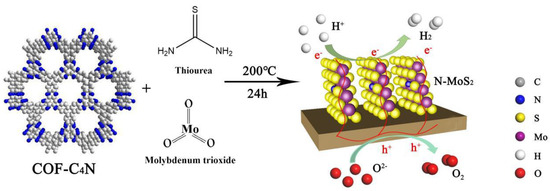
Figure 1.
Schematic illustration of synthesis route to vertical N-MoS2/COF-C4N for both HER and OER.
2. Experimental Section
2.1. Material and Instrumentation
Hexaketocyclohexane octahydrate, 1, 4-dioxane (C4H8O2), 1, 3, 5-trimethyl- benzene, 2, 3, 6, 7, 10, 11-hexaaminotriphenylene (C18H24Cl6N6), acetic acid, thiourea, molybdenum trioxide, and tetrahydrofuran. All solvents and reagents are obtained from commercial sources without further purification. The structure, composition, and texture properties of the materials were studied by powder X-ray (PXRD) diffraction (Bruker D8 X-ray diffractometer), Fourier transform infrared (FT-IR) spectra (Spectrum 100), scanning electron microscopy (SEM) micrographs (Hitachi S-4800), transmission electron microscopy (TEM) experiment (JEM-2100 electron microscope). X-ray photoelectron spectroscopy (XPS) was used an ESCALAB 250 Xi from Thermo SCIENTIFIC in 27 Xinjinqiao Road, Pudong New Area, Shanghai and the C1s peak at 284.6 eV as the internal standard. Before the measurement, the sample was first degassed at 120 °C for 12 h.
2.2. Preparation Procedures of the Catalysts
2.2.1. Synthesis of COF-C4N
Put 3-symmetric 2, 3, 6, 7, 10, 11-triphenylhexamine 6 HCl (TPHA, 25.5 mg, 0.08 mmol) and C3 symmetric hexaketocyclohexane octahydrate (HKH, 25.0 mg, 0.08 mmol), 1.5 mL 1, 4-dioxane, and 1.5 mL 1, 3, 5-trimethylbenzene into a 10 mL tube. The mixture was sonicated at 25 °C for 30 min, and then 4 M aqueous acetic acid solution (0.5 mL) was added to the test tube. The tube was degassed using three freeze-pump-thaw cycles and then sealed and kept in an air-dry oven at 150 ℃ for 3 days. The precipitate was filtered and thoroughly cleaned by Soxhlet extraction with tetrahydrofuran and acetone respectively. Finally, it was freeze-dried at 120 ℃ under reduced pressure (−0.09 MPa) for 12 h.
2.2.2. Synthesis of N-MoS2
As a comparison, we used the same method to synthesize N-doped MoS2 (N-MoS2) alone in the absence of COF-C4N. We dissolved 29.55 mg thiourea and 28.60 mg molybdenum trioxide in ultra-pure water, and the mixture was sonicated for 3 min until homogeneous dispersion. After stirring for 30 min, the dispersion was heated at 200 °C for 24 h. The obtained precipitate was filtered and washed several times with ultra-pure water, then dried in a drying oven at 100 °C for 12 h.
2.2.3. Synthesis of π-π N-MoS2/COF-C4N
As-prepared 15 mg of COF-C4N and 15 mg as-prepared of MoS2 were dissolved in ultrapure water, and the mixture was sonicated for 30 min until homogeneous dispersion. The dispersion was heated at 200 °C for 24 h. The obtained precipitate was filtered and washed several times with ultrapure water and then dried in a drying oven at 100 °C for 12 h.
2.2.4. Synthesis of Vertical N-MoS2/COF-C4N Heterojunction
We dissolved 29.55 mg thiourea and 28.60 mg molybdenum trioxide in ultra-pure water, and the mixture was sonicated for 3 min until homogeneous dispersion. As-prepared 15 mg COF-C4N was added to the dispersion. After stirring for 30 min, the dispersion was heated at 200 °C for 24 h. The obtained precipitate was filtered and washed several times wih ultra-pure water, then was dried in drying oven at 100 °C for 12 h. Through this in-situ hydrothermal process, N-MoS2 nanosheets could be grown vertically on COF-C4N, forming the N-MoS2/COF-C4N vertical heterostructure.
2.3. Electrochemical Measurements
All electrochemical measurements were performed at room temperature on the Chi660e electrochemical workstation with standard three electrode channels. The three-electrode system includes catalyst-coated carbon fiber cloth as the working electrode, Ag/AgCl (saturated KCl) as the reference electrode, and carbon electrode as the counter electrode. All potential measurements were converted to the RHE according to the following formula E vs. RHE = EvsAg/AgCl + EθAg/AgCl + 0.059 pH (in volts). The working electrode was prepared as follows: 10 mg catalyst powders and 10 mg carbon black were ground and dispersed in 1 mL DI water-ethanol mixed solution, and 10 μL nafion was added into the mixture before they were sonicated for 20 min. The above solution was drop-cast onto the surface of a conductive carbon fiber at a catalyst loading of 50 μL cm−2. To accelerate the catalyst drying onto the carbon fiber the use of infrared lamps. The HER performance of prepared products was evaluated in 0.5 M H2SO4 solution as the electrolyte.
Linear scan voltammetric curves (LSVs) of OER were obtained in nitrogen-saturated KOH solution at 1600 rpm speed and 5 mV s−1 scanning speed. The overpotential is obtained according to the following equation: η = ERHE − 1.23 V. Calculation of the Tafel slope according to Tafel equation: η = blog j + a, where η is the overpotential (V), j is the current density (mA cm−2), and b is the Tafel slope (mV dec−1). The CVs of the samples were measured in 1 M KOH solution at scanning rates (20, 40, 60, 80, and 100 mV s−1) to compare the effective electrode surface area (ECSA) of the relevant samples. Electrochemical impedance spectroscopy (EIS) was tested in potentiostatic mode of 1.579 V vs. RHE (@10 mA cm−2), with OER ranging from 100 kHz to 0.1 Hz and an applied voltage amplitude of 5 mV. Electrochemical testing was carried out under the standard three-electrode system. The prepared samples were used as working electrodes, platinum plate (99.9%) as a counter electrode, saturated KCl Ag/AgCl electrode as reference electrode, and 0.5 M Na2SO4 solution as electrolyte. All experiments were carried out at room temperature, and before the experiment, high pure nitrogen was used to make bubbles through the electrolyte.
2.4. Computational Details
The density functional theory (DFT) calculations are performed. Device Studio program provides a number of functions for performing visualization, modeling, and simulation [51]. The interaction between the core and valence electrons is described using the frozen-core projector augmented wave (PAW) approach [52,53]. The generalized gradient approximation of the Perdew-Burke-Ernzerhof (PBE) functional is used [54]. The energy cutoff is set to be 500 eV. A Γ-centered mesh of 3 × 3 × 1 k-points is used to sample the two-dimensional Brillöuin zone for PBE. The vdW correction proposed by Grimme is adopted to describe long-range vdW interactions. [55] A vacuum space greater than 15 Å perpendicular to the sheet is applied to separate the interactions between neighboring slabs. All geometry structures are fully relaxed until the convergence criteria of energy and force are less than 10−5 eV and 0.01 eV Å−1, respectively.
The free energy difference for HER was calculated according to the approach originally proposed by Nørskov and coworkers: [56,57]
ΔG = ΔE + ΔEZPE − TΔS + ΔGpH + ΔGU
In this equation, ΔE is the difference in electronic energy before and after hydrogenation extracted directly from first-principles calculations and ΔEZPE and ΔS are the zero-point energy correction and entropy change between the absorbed state and gas phase obtained from frequency calculations at 298 K, respectively. The pH dependence of the reduction potential is considered by ΔGpH = 0.059 × pH, which originates from the H+ concentration dependence of the entropy [58] The external potential supplied by photogenerated electrons is added by ΔGU = −eU, where U is the electrode potential relative to the standard hydrogen electrodes.
The HER pathways on 2D-COFs are divided into two elementary steps of forming intermediate H* on the material surface and then H* transforms into H2 molecule.
A: * + H+ + e- → H*
B: H* + H+ + e- → * + H2
3. Results and Discussions
3.1. Characterizations
The crystalline structures of samples were investigated by XRD analysis. The X-ray diffraction (XRD) patterns of COF-C4N, N-MoS2, N-MoS2/COF-C4N, and the standard spectrum of 2H-MoS2 (PDF#87-2416) are shown in Figure 2a. One can see the N-MoS2 showed three peaks at 14.4°, 32.6° and 59.3° mainly, corresponding to the (002), (100), and (110) lattice plane, in agreement with the 2H-MoS2 (PDF#87-2416). However, the peak at about 29°, 39.5°, and 50° become very gentle, which indicates the destruction of some two-dimensional structures of MoS2 and the formation of abundant defects with the N-doping. For the COF-C4N, the peak at 7.2° corresponds to its (100) plane, indicating its ordered skeletal structure, and the peak at ∼27° corresponds to its (001) plane ascribed to their π-π stacking structure. For N-MoS2/COF-C4N composite, the peak corresponding to the (100) plane of COF-C4N could still be found and shift under the influence of N-MoS2. The peak at 27° also becomes weaker relative to COF-C4N, demonstrating that the skeleton structure of COF-C4N as a substrate is not significantly affected by the in-situ growing of N-MoS2, but the π−π interlayer interactions are weakened. The peaks at 32.6° and 59.3° corresponding to the 100 and 110 planes of N-MoS2 still appeared but the 002 plane almost disappeared in XRD patterns of N-MoS2/COF-C4N, which implies that N-MoS2 may grow on the surface of COF-C4N uniformly. Fourier transform infrared (FTIR) spectra of commercial MoS2, N-MoS2, COF-C4N, and N-MoS2/COF-C4N are shown in Figure 2b. Comparing our synthesized N-MoS2 with the commercial MoS2 sample, the peak at 1130 cm−1 became stronger, which is attributed to the disruption of the symmetry of the original MoS2. The change of the absorption peaks in the range of 1652-1336 cm−2 ascribes to the enhancement of the N doping absorption peak, which also demonstrates the formation of N-doped defects. In addition, the peak at 2927 cm−1 corresponding to the N-H vibrations was found in N-MoS2, demonstrating to the existence of the NH2 group at the edge of N-MoS2. In Figure 2b, the phenazine linkages for the COF-C4N with characteristic bands at 1509 cm−1, 1458 cm−1, and 1389 cm−1 were detected. For the N-MoS2/COF-C4N, the characteristic peaks of both N-MoS2 and COF-C4N could be found, indicating that the composites are successfully assembled. The peak at 2927 cm−1 was still found in the FT-IR spectra of N-MoS2/COF-C4N. It is concluded that N-MoS2 grows vertically on the COF-C4N by N...H hydrogen bond interaction between the NH2 group at the edge of N-MoS2 and N atom in COF-C4N.
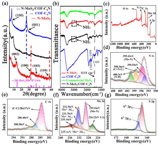
Figure 2.
(a) XRD pattern of COF-C4N, vertical N-MoS2/COF-C4N, N-MoS2; (b) FTIR spectra of commercial MoS2, N-MoS2, COF-C4N, and vertical N-MoS2/COF-C4N; XPS spectra of (c) XPS survey, (d) N 1s, (e) C 1s, (f) Mo 3d and (g) S 2p.
The chemical composition was investigated by X-ray photoelectron spectroscopic (XPS), as shown in Figure 2c–g. Figure 2c displays the presence of C, N, O, Mo, and S N-MoS2/COF-C4N. The N 1s spectra shown in Figure 2d can be resolved into four peaks at 394.54 eV, 395.41 eV, 398.36 eV, and 400.30 eV, respectively. The peak at 395.41 eV corresponds to Mo2N (3p3/2), which may be caused by the coordination between the Mo and N (Mo-N bond). The peak at 400.30 eV corresponding to the N-H bond further confirms the possible existence of the NH2 group at the edge of N-MoS2 and N-MoS2 growing vertically on the COF-C4N by the N...H hydrogen bond. The N 1s peaks at 398.36 eV refer to the sp2-hybridized nitrogen C=N-C bond of COF-C4N. In the C 1s spectra (Figure 2e), the peak at 284.57 eV can be attributed to the C-C bond of COF-C4N. As shown in Figure 2f, the Mo 3d spectra can be resolved into five peaks at 226.22 eV, 229.16 eV, 231.79 eV, 232.36 eV and 235.14 eV, respectively. The strongest peak centered at 229.16 eV corresponds to the Mo-N bond, which can further demonstrate the existence of N-doped defects and interactive forms of Mo and N.
Transmission electron microscopy (TEM) images and scanning electron microscopy (SEM) images are also tested to confirm the morphologies and structures of as-synthesized COF-C4N, N-MoS2, and N-MoS2/COF-C4N (Figure 3a–k). As shown in Figure 3a it is clear that there are uniformly distributed pores on the surface of COF-C4N, SEM images in Figure 3d showed a sheet-like morphology of COF-C4N [48]. TEM and SEM of as-synthesized N-MoS2 by thiourea and molybdenum trioxide without any substrate at the same experimental conditions (Figure 3b,e) are compared with TEM and SEM images of N-MoS2/COF-C4N heterojunctions prepared by in situ synthesis N-MoS2 on COF-C4N (Figure 3c,f). One can see from Figure 3c that the N-MoS2 grows uniformly on the surface of COF-C4N with high coverage and the distance of two lattice fringes becomes larger (from 0.626 nm of N-MoS2 to 0.880 nm of heterojunctions), which implies that more active sites expose easily and the better charge transfer between the interfaces and consequently will contribute to the enhancement of catalysis activity. From Figure 3f, it is clear that a super thin sheet-like and petal-like N-MoS2 grows almost vertically on the surface of COF-C4N, which can prove that the vertical heterojunction is formed. The corresponding energy dispersive spectrometer (EDS) images (Figure 3g–k) also present the uniform distribution of Mo, S, N, and C elements, which can further confirm the N-MoS2 uniformly dispersed on the COF-C4N-sheet surface.
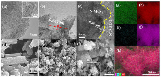
Figure 3.
TEM images of (a) COF-C4N, (b) N-MoS2, (c) N-MoS2/COF-C4N; SEM images of (d) COF-C4N, (e) N-MoS2, (f) vertical N-MoS2/COF-C4N. STEM-EDS mapping of vertical N-MoS2/COF-C4N with (g) Mo, (h) N, (i) C, (j) S, (k) EDS layered image.
3.2. Electrocatalytic Performance
Linear sweep voltammetry (LSV) was recorded to examine the cathodic HER reaction in N2 saturated 0.5 M H2SO4 solution from −1.0 V to 0.0 V with a scan rate of 5 mV s−1 in order to determine the electrocatalytic activity of the as-synthesized catalyst. The HER LSV curves of commercial MoS2, N-MoS2(in-situ synthesized), COF-C4N, and three mass ratios N-MoS2/COF-C4N are all given in Figure 4a. It is obvious that commercial MoS2 (630 mV at 10 mA cm−2) and COF-C4N (650 mV at 10 mA cm−2) did not show HER activity at all. However, N-MoS2 obtained by in-situ synthesis exhibits certain HER activity (370 mV at 10 mA cm−2) due to the exposure of more N-doping defective sites. After the vertical heterojunction formation, the overpotential of N-MoS2/COF-C4N is noticeably smaller than that of both N-MoS2 and COF-C4N. The complex N-MoS2/COF-C4N1:1 shows the most excellent HER activity with 106 mV at 10 mA cm−2, which indicates the N-MoS2 grows vertically on COF-C4N sheets with the best uniformity and high coverage at the mass ratio of 1:1. When the ratio of N-MoS2 gets higher, the HER activity declines significantly. The excessive N-MoS2 will cover the pores of COF-C4N, which impacts the electrical conductivity of COF-C4N, electronic transmission speed, and catalytic activity of catalysts. As a comparison, the common π-π N-MoS2/COF-C4N heterojunction by ultrasonic dispersion synthesis method was also prepared and taken LSV test for HER activity with 358 mV at 10 mA cm−2, the results show that a vertical in-situ growing produces better HER activity and this vertical stacking may benefit the electrolyte penetration and bubble release, charge transfer as well as active sites (N and S edge sites) exposure for catalytic promotions. Tafel slopes are obtained by fitting the linear regions of Tafel plots to the Tafel equation , where b is the Tafel slope, j is the current density). Figure 4b presents Tafel plots of all the catalysts. One can see the Tafel slope of the N-MoS2/COF-C4N1:1 is lower than that of other prepared catalysts. A lower Tafel slope suggested an enhancement of HER currents with increasing applied potential, which further demonstrates its superior performance. Using the voltage @ 10 mA cm−2, we also obtained the CV curves of N-MoS2/COF-C4N in 0.5 M H2SO4 saturated with N2 recorded at different scan rates (Figure 4c).
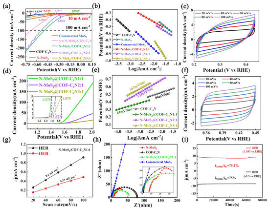
Figure 4.
HER and OER performance. (a) The HER LSV curves of the commercial MoS2, N-MoS2, COF-C4N, and the vertical N-MoS2/COF-C4N. (b) The corresponding HER Tafel plots. (c) The CV curves of the vertical N-MoS2/COF-C4N in 0.5 M H2SO4 saturated with N2. (d) The OER LSV curves of the vertical N-MoS2/COF-C4N. (e) The corresponding OER Tafel plots. (f) The CV curves of the vertical N-MoS2/COF-C4N in 1 M KOH saturated with N2. (g) Capacitive currents versus scan rates on the basis of CV curves recorded at different scan rates. (h) EIS Nyquist plots of the commercial MoS2, N-MoS2, COF-C4N, and the vertical N-MoS2/COF-C4N. (i) Chronoamperometric durability test of the vertical N-MoS2/COF-C4N at 0.3 V in 0.5 M H2SO4 for HER and at 1.579 V in 1 M KOH for OER.
In order to check if this vertical N-MoS2/COF-C4N could keep OER activity after forming complex heterojunction, linear scan voltammetric curves (LSVs) of OER were obtained in N2 saturated 1M KOH solution at a 1600 rpm speed and 5 mV s−1 scanning speed, as shown in Figure 4d. The vertical N-MoS2/COF-C4N requires a small overpotential of 349 mV to achieve the current densities of 10 mA cm−2 and almost equal to the overpotential of pristine COF-C4N. The OER Tafel slope of the N-MoS2/COF-C4N1:1 is also lower than that of other prepared catalysts (Figure 4e). The CV curves of vertical N-MoS2/COF-C4N in 1 M KOH saturated with N2 is also given in Figure 4f. Based on the CV curves in Figure 4c and 4f, the obtained current densities are plotted as a function of scan rate as shown in Figure 4g. Obviously, the vertical N-MoS2/COF-C4N possesses relatively larger electrochemical double layer capacitances value (8.20 and 4.19 mF cm−2 for HER and OER respectively), which means that it holds a larger electrochemical surface area for both electrocatalytic HER and OER. In order to make sure if this vertical heterojunction could possess electrocatalytic water splitting, we conducted a measurement using a two-electrode set-up to test electrocatalytic water splitting on this vertical N-MoS2/COF-C4N as shown in Figure S1. The sample has almost shown no electrocatalytic water splitting performance. The results above show that the vertical heterojunction N-MoS2/COF-C4N are bifunctional electrocatalysts. The HER and OER activity comparison with recent other reports is listed in Table S1, which indicates the excellent performance of this vertical heterojunction based on a non-precious metal catalyst.
The N-MoS2 part in the vertical heterojunction N-MoS2/COF-C4N mainly contributed to HER activity and the N-doping defected sites should be the HER active sites. The OER activity is mainly from COF-C4N. The increasing HER activity and invariant OER activity indicate the backbone structure of COF-C4N as a substrate is maintained and the charge transfer between interfaces is enhanced when the vertical heterojunction is formed by the in-situ synthesis method. The electrochemical impedance spectroscopic (EIS) Nyquist plots of commercial MoS2, N-MoS2, COF-C4N, and the vertical N-MoS2/COF-C4N1:1 is presented in Figure 4h. The smaller polarization resistance of the vertical N-MoS2/COF-C4N1:1 verified the enhanced charge transfer kinetics and faster electron transfer process. Figure 4i shows the long-term durability measured by performing continuous HER at a static overpotential of −0.3 V and OER at a static overpotential of 1.579 V. The current density with a little decrease as the reaction proceeded for 20 h. (i7200s/i0s = 75% for HER and i7200s/i0s = 79.2% for OER). The SEM and XPS after 20 h electrolysis reaction was also measured for studying the change of morphology characterization and surface chemical structure. It can be seen from Figure S2 that the sample after the reaction has a little agglomeration, but most of the samples maintain the vertical heterojunction structure well. XPS after 20 h reaction in Figure S3 also did not show a large change on the whole, except that the peak centered at 229.16 eV corresponding to the Mo-N bond in Mo 3d spectra shifts to a lower binding energy and the peak at 395.41 eV corresponding to Mo2N in N 1s spectra is weaker, which explained the decrease of catalytic activity after 20 h. EDS test was conducted on samples before and after the electrocatalytic process, and the change of Mo content was used to determine Mo leaking. It can be seen from Figure S4 and Table S2 that the content of Mo in the sample after the electrocatalytic reaction is less than that before the reaction, so it is proved that the material has some Mo leaking.
3.3. Mechanism Based on DFT Calculations
In order to explain the experimental results and further reveal the electrocatalytic activity mechanism for bifunctional HER and OER, the theoretical calculation investigations are explored on the basis of geometrical optimization, electronic properties and the free energy change of HER pathway on different active sites by using density functional theory (DFT). The vertical N-MoS2/COF-C4N heterostructure is constructed by Device Studio as shown in Figure 5a. The optimized stable structure verifies N-MoS2 could grow vertically on the surface of COF-C4N by a weak hydrogen bond (2.375 Å) between N atom of COF-C4N and H atom in NH2 group at the edge of N-MoS2. This vertical heterostructure is thought to be more active sites exposure. S atom of pure MoS2 is commonly considered as the active site for HER process, the H free radical adsorbing model on S site for pure MoS2 is given in Figure 5b. At the same time, based on the experimental results and theoretical analysis, there are two N-doping defected models suggested for N-MoS2 as shown in Figure 5b (N-MoS2 model 1 is obtained by using one N atom replacing S active site and N-MoS2 model 2 is obtained by N atom adsorbing on MoS2 surface and interact with both Mo and S). Gibbs free energies of HER profiles for two N-MoS2 models and pure MoS2 are calculated and shown in Figure 5c. It is evident that Gibbs free energy (ΔGH*) of *H intermediate for pure MoS2 is very high (1.79 eV), which verified its poor HER activity. In contrast, ΔGH* of N-MoS2 model 1 and 2 are much lower than that of pure MoS2. The N-MoS2 model 1 shows the lowest ΔGH* value (−1.50 eV), but the H2 desorption is the most difficult. Therefore N-MoS2 model 2 with ΔGH* = −0.79 eV was suggested as the most likely N-MoS2 defect structure. Finally, the charge density difference for MoS2/COF-C4N, π-π N-MoS2/COF-C4N, and vertical N-MoS2/COF-C4N are computed and compared in Figure 5d. It is theoretically verified that HER activity is mainly from N-MoS2 due to electrons accumulating on the MoS2 or N-MoS2 section. The electron transfer from COF-C4N to N-MoS2 is 0.217 e for vertical N-MoS2/COF-C4N, much larger than the electron transfer for MoS2/COF-C4N and π-π N-MoS2/COF-C4N, which is in good agreement with experimental and further explain the optimal electrocatalytic HER and OER activities for vertical N-MoS2/COF-C4N. Both the experimental and computational investigations demonstrate that the strategy of in-situ synthesis of N-MoS2 on COF-C4N to obtain vertical N-MoS2/COF-C4N heterojunction makes N-MoS2 dispersed well on the COF-C4N surface, N-MoS2 exposed more active sites and better charge transfer, so that vertical N-MoS2/COF-C4N maintains the excellent metal-free OER activity of COF-C4N and shows enhanced HER activity.
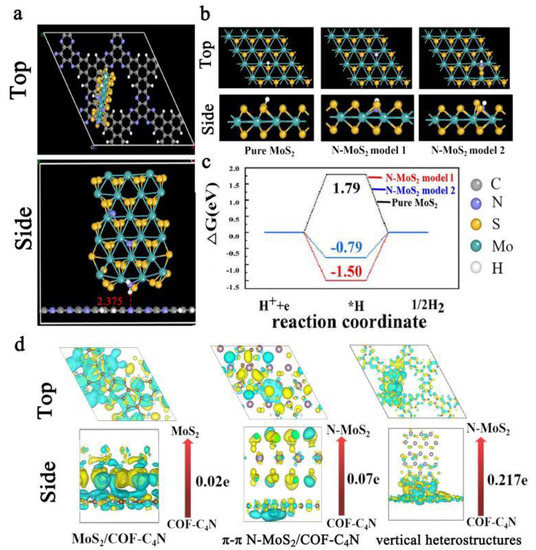
Figure 5.
(a) Top-view and side-view of the optimized unit cell of N-MoS2/COF-C4N vertical heterostructures drawing with Device Studio (the hydrogen bond are marked); (b) top-view and side-view of optimized *H intermediate of pure MoS2 (S as active site), N-MoS2 model 1 (N atom replacing S active site) and N-MoS2 model 2 (N atom adsorbing on MoS2 surface and interact with both Mo and S); (c) Gibbs free energy of HER profile for different active sites on various models; (d) charge density differences for MoS2/COF-C4N, π-π N-MoS2/COF-C4N and vertical heterostructures. The yellow and cyan regions represent electron accumulation and depletion, and the isosurface value is 0.0009 e A−3.
4. Conclusions
In summary, an in-situ growing synthesis method was used to prepare a vertical heterostructure N-MoS2/COF-C4N as efficient bifunctional electrocatalysts for HER with a low overpotential of 106 mV @ 10 mA cm−2 and OER with 349 mV at 10 mA cm−2. Experimental characterization and theoretical calculations both confirmed this vertical heterostructure, in which the interface interaction is the hydrogen bond between N of COF-C4N and the H atom of the NH2 group at the edge of N-MoS2. It is verified that the N-MoS2 part in the vertical heterojunction mainly contributed to HER activity and the N-doping defected sites (model 2) are the primary HER active sites with appropriate H radical adsorption free energy and hydrogen desorption free energy. C sites of COF-C4N are fully exposed due to the vertical growth of N-MoS2, resulting in an unaltered and excellent OER activity. The better charge transfer in this vertical N-MoS2/COF-C4N heterojunction is another reason for the excellent HER and OER catalytic performance.
Supplementary Materials
The following supporting information can be downloaded at: https://www.mdpi.com/article/10.3390/catal13010090/s1, Figure S1 Polarization curves of overall water splitting based on N-MoS2/COF-C4N; Figure S2. SEM measurements of electrocatalytic tested the vertical N-MoS2/COF-C4N after 20 h ghronoamperometric durability test at an applied potential of 0.106 V in 0.5 M H2SO4 solution; Figure S3. XPS of electrocatalytic tested the vertical N-MoS2/COF-C4N after 20 h ghronoamperometric durability test at an applied potential of 0.106 V in 0.5 M H2SO4 solution; Figure S4. STM and STEM-EDS mapping of vertical N-MoS2/COF-C4N with (a) the sample before reaction. (b) the sample after the reaction; Table S1. Comparison of HER and OER electrocatalytic performance with recent other reports; Table S2. The EDS Mapping Mo content comparison before and after 20 h ghronoamperometric durability test at an applied potential of 0.106 V in 0.5 M H2SO4 solution.
Author Contributions
Conceptualization, Z.Y. and H.Y.; methodology, F.Z.; software, N.Z.; validation, N.Z., W.L. and F.Z.; formal analysis, W.L. and H.Y.; investigation, N.Z. and W.L.; resources, H.Y.; data curation, N.Z. and W.L.; writing—original draft preparation, N.Z.; writing—review and editing, Z.Y.; visualization, N.Z.; supervision, Z.Y.; project administration, Z.Y.; funding acquisition, Z.Y. and H.Y. All authors have read and agreed to the published version of the manuscript.
Funding
This research was funded by the Natural Science Foundation of China (grant number 52273288 and 22278099) and the National Science Foundation of Heilongjiang Province (grant number LH2021B014).
Data Availability Statement
Data is contained within the article or Supplementary Materials.
Acknowledgments
This work was financially supported by the Natural Science Foundation of China (No.52273288 and 22278099) and the National Science Foundation of Heilongjiang Province (No. LH2021B014). We gratefully acknowledge HZWTECH for providing computation facilities.
Conflicts of Interest
The authors declare no conflict of interest.
References
- Zang, Y.P.; Niu, S.W.; Wu, Y.S.; Zheng, X.S.; Cai, J.Y.; Ye, J.; Xie, Y.F.; Liu, Y.; Zhou, J.B.; Zhu, J.F.; et al. Tuning orbital orientation endows molybdenum disulfide with exceptional alkaline hydrogen evolution capability. Nat. Commun. 2019, 10, 1217. [Google Scholar] [CrossRef] [PubMed]
- Lui, X.; Zhang, X.Y.; Li, D.S.; Zhang, S.Q.; Zhang, Q.H. Recent advances in the “on–off” approaches for on-demand liquid-phase hydrogen evolution. J. Mater. Chem. A 2021, 9, 18164–18174. [Google Scholar]
- Das, D.; Santra, S.; Nanda, K.K. In-situ fabrication of Nickel/Molybdenum carbide anchored N-doped graphene/CNT hybrid: An efficient (pre)catalyst for OER and HER. ACS Appl. Mater. Interfaces 2018, 10, 35025–35038. [Google Scholar] [CrossRef] [PubMed]
- Mohanty, B.; Jena, B.K.; Basu, S. Single Atom on the 2D Matrix: An emerging electrocatalyst for energy applications. ACS Omega 2020, 5, 1287–1295. [Google Scholar] [CrossRef]
- Zhou, G.Z.; Liu, G.S.; Liu, X.B.; Yu, Q.P.; Mao, H.M.; Xiao, Z.Y.; Wang, L. 1D/3D Heterogeneous assembling body as trifunctional electrocatalysts enabling Zinc-Air battery and self-powered overall water splitting. Adv. Funct. Mater. 2022, 32, 2107608. [Google Scholar] [CrossRef]
- Pan, Y.D.; Abazari, R.; Wu, Y.H.; Gao, J.K.; Zhang, Q.H. Advances in metal–organic frameworks and their derivatives for diverse electrocatalytic applications. Electrochem. Commun. 2021, 126, 1388–2481. [Google Scholar] [CrossRef]
- Doan, T.L.L.; Nguyen, D.C.; Prabhakaran, S.; Kim, D.H.; Tran, D.T.; Kim, N.H.; Lee, J.H. Single-atom Co-decorated MoS2 nanosheets assembled on metal nitride nanorod arrays as an efficient bifunctional electrocatalyst for pH-universal water splitting. Adv. Funct. Mater. 2021, 31, 2100233. [Google Scholar] [CrossRef]
- Jin, H.; Choi, S.; Bang, G.J.; Kwon, T.; Kim, H.S.; Lee, S.J.; Hong, Y.; Lee, D.W.; Park, H.S.; Baik, H.; et al. Safeguarding RuO2 phase against lattice oxygen oxidation during acidic water electrooxidation. Energy Environ. Sci. 2022, 15, 1119–1130. [Google Scholar] [CrossRef]
- Chu, H.Q.; Feng, P.P.; Jin, B.; Ye, G.; Cui, S.S.; Zheng, M.; Zhang, G.X.; Yang, M. In-situ release of phosphorus combined with rapid surface reconstruction for Co–Ni bimetallic phosphides boosting efficient overall water splitting. Chem. Eng. J. 2021, 11, 1385–8947. [Google Scholar] [CrossRef]
- Lu, S.S.; Shi, Y.M.; Zhou, W.; Zhang, Z.P.; Wu, F.; Zhang, B. Dissolution of the heteroatom dopants and formation of ortho quinone moieties in the doped carbon materials during water electrooxidation. J. Am. Chem. Soc. 2022, 144, 3250–3258. [Google Scholar] [CrossRef]
- Lu, S.S.; Zhou, W.; Shi, Y.M.; Liu, C.B.; Yu, Y.F.; Zhang, B. Phenanthrenequinone-like moiety functionalized carbon for electrocatalytic acidic oxygen evolution. Chem 2022, 8, 1415–1426. [Google Scholar] [CrossRef]
- Xing, Y.M.; Zhang, X.H.; Liu, D.H.; Li, W.H.; Sun, L.N.; Geng, H.B.; Zhang, J.P.; Guan, H.Y.; Wu, X.L. Porous amorphous Co2P/N, B-Co-doped carbon composite as an improved anode material for sodium-ion batteries. ChemElectroChem 2017, 4, 1395–1401. [Google Scholar] [CrossRef]
- Chen, Z.Y.; Song, Y.; Cai, J.Y.; Zheng, X.S.; Han, D.D.; Wu, Y.S. Tailoring the d-band centers enables Co4N nanosheets to be highly active for hydrogen evolution catalysis. Angew. Chem. Int. Ed. 2018, 57, 5076–5080. [Google Scholar] [CrossRef]
- Zhuang, W.; Wang, Y.; Xu, C.Q.; Liu, S.J.; Chen, C.; Peng, Q.; Zhuang, Z.B.; Xiao, H.; Pan, Y.; Lu, S.Q.; et al. Three-dimensional open nano-netcage electrocatalysts for efficient pH-universal overall water splitting. Nat. Commun. 2019, 10, 4875. [Google Scholar] [CrossRef]
- Zhai, P.L.; Xia, M.Y.; Wu, Y.Z.; Zhang, G.H.; Gao, J.F.; Zhang, B.; Cao, S.Y.; Zhang, Y.T.; Li, Z.W.; Fan, Z.Z.; et al. Engineering single-atomic ruthenium catalytic sites on defective nickel-iron layered double hydroxide for overall water splitting. Nat. Commun. 2021, 12, 4587. [Google Scholar] [CrossRef] [PubMed]
- Xu, X.J.; Li, F.K.; Zhang, D.C.; Liu, Z.B.; Zuo, S.Y.; Zeng, Z.Y.; Liu, J. Self-sacrifice template construction of uniform yolk-shell ZnS@C for superior alkali-ion storage. Adv. Sci. 2022, 2200247. [Google Scholar] [CrossRef] [PubMed]
- Qin, H.F.; Luo, S.P.; Li, Y.; Zhang, Y.F.; Dong, R.Y.; Zhou, Y.; Luo, J.; Zhu, Y.L.; Jiang, F. Imidazole-modified lignin as a suitable substrate for synthesis of N and S Co-doped carbon supporte cobalt sulfide dual-functional electrocatalyst for overall water splitting. J. Power Sources 2022, 7, 2200060. [Google Scholar]
- Yang, J.Y.; Chai, C.L.; Jiang, C.; Liu, L.; Xi, J.Y. MoS2–CoS2 heteronanosheet arrays coated on porous carbon microtube textile for overall water splitting. J. Power Sources 2021, 514, 230580. [Google Scholar] [CrossRef]
- Hinnemann, B.; Moses, P.G.; Bonde, J.; Jørgensen, K.P.; Nielsen, J.H.; Horch, S.; Chorkendorff, I.; Norskov, J.K. Biomimetic hydrogen evolution: MoS2 nanoparticles as catalyst for hydrogen evolution. J. Am. Chem. Soc. 2005, 127, 5308–5309. [Google Scholar] [CrossRef]
- Chen, M.; Smart, T.J.; Wang, S.; Kou, T.; Lin, D.; Ping, Y.; Li, Y. The coupling of experiments with density functional theory in the studies of the electrochemical hydrogen evolution reaction. J. Mater. Chem. A 2020, 8, 8783–8812. [Google Scholar] [CrossRef]
- Wei, C.B.; Liu, C.; Gao, L.N.; Sun, Y.F.; Liu, Q.Y.; Zhang, X.; Guo, J.X. MoS2 nanosheets decorated Ni(OH)2 nanorod array for active overall water splitting. J. Alloy. Compd. 2019, 796, 86–92. [Google Scholar] [CrossRef]
- Yu, Z.Y.; Duan, Y.; Kong, Y.; Zhang, X.L.; Feng, X.Y.; Chen, Y.; Wang, H.J.; Yu, X.X.; Ma, T.; Zheng, X.S.; et al. General synthesis of tube-like nanostructured perovskite oxides with tunable transition metal−oxygen covalency for efficient water electrooxidation in neutral media. J. Am. Chem. Soc. 2022, 144, 13163–13173. [Google Scholar] [CrossRef] [PubMed]
- Yu, M.H.; Zhao, H.; Feng, B.; Hu, L.; Zhang, X.Y.; Zeng, Y.X.; Tong, Y.X.; Lu, X.H. Engineering thin MoS2 nanosheets on TiN nanorods: Advanced electrochemical capacitor electrode and hydrogen evolution electrocatalyst. ACS. Energy Lett. 2017, 2, 1862–1868. [Google Scholar] [CrossRef]
- Deng, S.J.; Yang, F.; Zhang, Q.H. Phase modulation of (1T-2H)-MoSe2/TiC-C shell/core arrays via nitrogen doping for highly efficient hydrogen evolution reaction. Adv. Mater. 2018, 30, 1802223. [Google Scholar] [CrossRef]
- Chen, S.Y.; Luo, T.; Li, X.Q.; Chen, K.J.; Fu, J.W.; Liu, K.; Cai, C.; Wang, Q.Y.; Li, H.M. Identification of the highly active Co−N4 coordination motif for selective oxygen reduction to hydrogen peroxide. J. Am. Chem. Soc. 2022, 144, 14505–14516. [Google Scholar] [CrossRef]
- Dong, K.; Lei, Y.; Zhao, H.; Liang, J.; Ding, P.; Liu, Q.; Xu, Z.; Lu, S.; Li, Q.; Sun, X. Noble-metal-free electrocatalysts toward H2O2 production. J. Mater. Chem. A 2020, 8, 23123–23141. [Google Scholar] [CrossRef]
- Wang, M.; Zhang, N.; Feng, Y.; Hu, Z.; Shao, Q.; Huang, X. Partially pyrolyzed binary metal-organic framework nanosheets for efficient electrochemical hydrogen peroxide synthesis. Angew. Chem. Int. Ed. 2020, 59, 14373–14377. [Google Scholar] [CrossRef]
- Jirkovský, J.S.; Halasa, M.; Schiffrin, D.J. Kinetics of electrocatalytic reduction of oxygen and hydrogen peroxide on dispersed gold nanoparticles. Phys. Chem. Chem. Phys. 2010, 12, 8042–8053. [Google Scholar] [CrossRef]
- Chen, Z.; Niu, H.; Ding, J.; Liu, H.; Chen, P.H.; Lu, Y.H.; Lu, Y.R.; Zuo, W.; Han, L.; Guo, Y.; et al. Unraveling the origin of sulfur-doped Fe-N-C single-atom catalyst for enhanced oxygen reduction activity: Effect of iron spin-state tuning. Angew. Chem. Int. Ed. 2021, 60, 25404–25410. [Google Scholar] [CrossRef]
- Zhao, Q.; Wang, Y.; Lai, W.H.; Xiao, F.; Lyu, Y.; Liao, C.; Shao, M. Approaching a high-rate and sustainable production of hydrogen peroxide: Oxygen reduction on Co-N-C single-atom electrocatalysts in simulated seawater. Energy Environ. Sci. 2021, 14, 5444–5456. [Google Scholar] [CrossRef]
- Zhao, G.Q.; Li, P.; Rui, K.; Chen, Y.P.; Dou, S.X.; Sun, W.P. CoSe2/MoSe2 Heterostructures with enriched water adsorption/dissociation sites towards enhanced alkaline hydrogen evolution reaction. Chem. Eur. J. 2018, 24, 11158–11165. [Google Scholar] [CrossRef]
- Xiong, Q.Z.; Wang, Y.; Liu, P.F.; Zheng, L.R.; Wang, G.Z.; Yang, H.G.; Wong, P.K.; Zhang, H.M.; Zhao, H.J. Cobalt covalent doping in MoS2 to induce bifunctionality of overall water splitting. Adv. Mater. 2018, 30, 1801450. [Google Scholar] [CrossRef]
- Liu, Y.D.; Chen, Y.; Tian, Y.H.; Sakthivel, T.; Liu, H.; Guo, S.W.; Zeng, H.B.; Dai, Z.F. Synergizing hydrogen spillover and deprotonation by internal polarization field in MoS2/NiPS3 vertical heterostructure for boosted water electrolysis. Adv. Mater. 2022, 34, 2203615. [Google Scholar] [CrossRef] [PubMed]
- Liu, T.; Gao, W.; Wang, Q.; Dou, M.; Zhang, Z.; Wang, F. Selective loading of atomic platinum on a RuCeOx support enables stable hydrogen evolution at high current densities. Angew. Chem. Int. Ed. 2020, 132, 20603. [Google Scholar] [CrossRef]
- Zhao, X.W.; Liu, Z.C.; Xiao, W.Y.; Huang, H.Y.; Zhang, L.H.; Cheng, Y.H.; Zhang, J.Y. Low crystalline MoS2 nanotubes from MoS2 nanomasks for lithium ion battery applications. ACS App. Energy Mater. 2020, 3, 7580–7586. [Google Scholar] [CrossRef]
- Xu, H.X.; Cheng, D.J.; Cao, D.P.; Zeng, X.C. A universal principle for a rational design of single-atom electrocatalysts. Nat. Catal. 2018, 1, 339–348. [Google Scholar] [CrossRef]
- Khaing, K.K.; Yin, D.G.; Ouyang, Y.G.; Xiao, S.T.; Liu, B.Q.; Deng, L.L.; Li, L.Q.; Guo, X.D.; Wang, J.; Liu, J.L.; et al. Fabrication of 2D−2D heterojunction catalyst with covalent organic framework (COF) and MoS2 for highly efficient photocatalytic degradation of organic pollutants. Inorg. Chem. 2020, 59, 6942–6952. [Google Scholar] [CrossRef] [PubMed]
- Yuan, Y.J.; Shen, Z.K.; Song, S.X.; Guan, J.; Bao, L.; Pei, L.; Su, Y.B.; Wu, S.T.; Bai, W.F.; Yu, Z.T.; et al. Co-P bonds as atomic-level charge transfer channel to boost photocatalytic H2 production of Co2P/black phosphorus nano sheets photocatalyst. ACS Catal. 2019, 1, 7801–7807. [Google Scholar] [CrossRef]
- Shao, L.X.; Liu, J.H.; Li, F.J.; Yang, H.; Zhang, X.Y.; Li, S.J.; Li, Y.Y.; Sun, P.F. Preparation and adsorption properties of TiO2/ MoS2 nanocomposites. Mater. Res. Express 2019, 6, 055046. [Google Scholar] [CrossRef]
- Lee, D.; Jang, A.R.; Kim, J.Y.; Lee, G.; Jung, D.W.; Lee, T.; Lee, J.; Kim, J.J. Phase-dependent gas sensitivity of MoS2 chemical sensors investigated with phase-locked MoS2. Nanotechnology 2020, 31, 225504. [Google Scholar] [CrossRef]
- Zhao, J.; Li, Q.Q.; Zhang, Q.H.; Liu, R. Carbon tube-graphene heterostructure with different N-doping configurations induces an electrochemically active-active interface for efficient oxygen electrocatalysis. Chem. Eng. J. 2022, 431, 133730. [Google Scholar] [CrossRef]
- Zhai, Q.L.; Han, S.M.; Hse, C.Y.; Jiang, J.C.; Xu, J.M. Electrocatalytic hydrogenation of mono- and dimeric lignin to hydrocarbons in fluidized electrocatalytic system. Fuel Process. Technol. 2022, 227, 107109. [Google Scholar] [CrossRef]
- Zhang, M.; Lu, M.; Lang, Z.L.; Liu, J.; Liu, M.; Chang, J.N.; Li, L.Y.; Shang, L.J.; Wang, M.; Li, S.L. Semiconductor/covalent-organic-framework Z-scheme heterojunctions for artificial photosynthesis. Angew. Chem. Int. Ed. 2020, 59, 6500–6506. [Google Scholar] [CrossRef]
- Mondal, S.; Mohanty, B.; Nurhuda, M.; Dalapati, S.; Jana, R.; Addicoat, M.; Datta, A.; Jena, B.K.; Bhaumik, A. A thiadiazole-based covalent organic framework: A metal-free electrocatalyst toward oxygen evolution reaction. ACS Catal. 2020, 10, 5623–5630. [Google Scholar] [CrossRef]
- Wu, D.K.; Xu, Q.; Qian, J.; Li, X.; Sun, Y. Bimetallic covalent organic frameworks for constructing multifunctional electrocatalyst. Chem. A Eur. J. 2019, 12, 3105–3111. [Google Scholar] [CrossRef] [PubMed]
- Zhao, X.J.; Pachfule, P.; Li, S.; Langenhahn, T.; Ye, M.Y.; Schlesiger, C.; Praetz, S.; Schmidt, J.; Thomas, A. Macro/microporous covalent organic frameworks for efficient electrocatalysis. J. Am. Chem. Soc. 2019, 114, 6623–6630. [Google Scholar] [CrossRef] [PubMed]
- Yang, C.H.; Yang, Z.D.; Dong, H.; Sun, N.; Lu, Y.; Zhang, F.M.; Zhang, G.L. Theory-driven design and targeting synthesis of a highly-conjugated basal-plane 2D covalent organic framework for metal free electrocatalytic OER. ACS Energy Lett. 2019, 4, 2251–2258. [Google Scholar] [CrossRef]
- Wu, A.Q.; Xie, Y.; Ma, H.; Tian, C.G.; Gu, Y.; Yan, H.J.; Zhang, X.M.; Yang, G.Y. Integrating the active OER and HER components as the heterostructures for the efficient overall water splitting. Nano Energy 2017, 17, 2211–2855. [Google Scholar] [CrossRef]
- Li, X.H.; Liu, F.; Zhang, W.F.; Lu, H.B.; Zhang, J. Electrocatalytical oxidation of arsenite by reduced graphene oxide via in-situ electrocatalytic generation of H2O2. Environ. Pollut. 2019, 254, 112958. [Google Scholar] [CrossRef] [PubMed]
- Mishra, R.K.; Choi, G.J.; Choi, H.J.; Singh, J.; Lee, S.H.; Gwag, J.S. Potentialities of nanostructured SnS2 for electrocatalytic water splitting: A review. J. Alloy. Compd. 2022, 921, 0925–8388. [Google Scholar] [CrossRef]
- Device Studio. Hongzhiwei Technology; Version 2021A; Device Studio: Shanghai, China, 2021; Available online: https://iresearch.net.cn/cloudSoftware (accessed on 1 November 2021).
- Blöchl, P.E. Projector augmented-wave method. Phys. Rev. B 1994, 50, 17953–17979. [Google Scholar] [CrossRef]
- Kresse, G.; Joubert, D. From ultrasoft pseudopotentials to the projector augmented-wave method. Phys. Rev. B 1999, 59, 1758–1779. [Google Scholar] [CrossRef]
- Perdew, J.P.; Burke, K.; Ernzerhof, M. Generalized gradient approximation made simple. Phys. Rev. Lett. 1996, 77, 3865–3868. [Google Scholar] [CrossRef]
- Grimme, S. Semiempirical GGA-type density functional constructed with a long-range dispersion correction. J. Comput. Chem. 2006, 27, 1787–1799. [Google Scholar] [CrossRef] [PubMed]
- Nørskov, J.K.; Rossmeisl, J.; Logadottir, A.; Lindqvist, L.; Kitchin, J.; Bligaard, T.; Jónsson, H. Origin of the overpotential for oxygen reduction at a fuel-cell cathode. J. Phys. Chem. B 2004, 108, 17886–17892. [Google Scholar] [CrossRef]
- Howalt, J.G.; Bligaard, T.; Rossmeisl, J.; Vegge, T. DFT based study of transition metal nano-clusters for electrochemical NH3 production. Phys. Chem. Chem. Phys. 2013, 15, 7785–7795. [Google Scholar] [CrossRef]
- Ertl, G.; Lee, S.B.; Weiss, W. Kinetics of nitrogen adsorption on Fe (111). Surf. Sci. 1982, 114, 515–526. [Google Scholar] [CrossRef]
Disclaimer/Publisher’s Note: The statements, opinions and data contained in all publications are solely those of the individual author(s) and contributor(s) and not of MDPI and/or the editor(s). MDPI and/or the editor(s) disclaim responsibility for any injury to people or property resulting from any ideas, methods, instructions or products referred to in the content. |
© 2023 by the authors. Licensee MDPI, Basel, Switzerland. This article is an open access article distributed under the terms and conditions of the Creative Commons Attribution (CC BY) license (https://creativecommons.org/licenses/by/4.0/).