Article

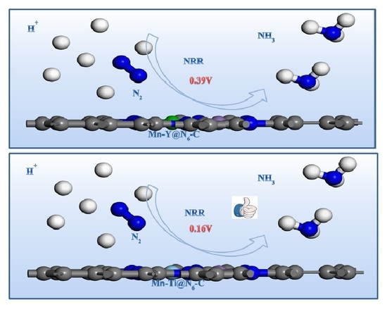
Nitrogen Reduction Reaction Catalyzed by Diatomic Metals Supported by N-Doped Graphite

1
School of Sciences, Xi’an Technological University, Xi’an 710021, China
2
Institute of Environmental and Energy Catalysis, School of Materials Science and Chemical Engineering, Xi’an Technological University, Xi’an 710021, China
3
Shaanxi Key Laboratory of Optoelectronic Functional Materials and Devices, School of Materials Science and Chemical Engineering, Xi’an Technological University, Xi’an 710021, China
*
Author to whom correspondence should be addressed.
Catalysts 2023, 13(1), 49; https://doi.org/10.3390/catal13010049
Submission received: 28 November 2022 / Revised: 17 December 2022 / Accepted: 23 December 2022 / Published: 26 December 2022
(This article belongs to the Special Issue Theory-Guided Electrocatalysis and Photocatalysis)

Abstract

:
In this article, for the transition metal-nitrogen ligand Mn-M@N6-C (M = Ag, Bi, Cd, Co, Cr, Cu, Fe, Hf, Ir, Mo, Nb, Ni, Os, Pd, Pt, Re, Rh, Ru, Sc, Ta, Tc, V, Y, Zn, Zr, Ti, W), by comparing the amount of change in the length of the N-N triple-bond, and calculating the adsorption energy of N2 and the change of charge around N2, it is shown that the activation effect of Sc, Ti, Y, Nb-Mn@N6-C on the single-atomic layer of graphite substrate is relatively good. The calculation of structural stability shows that the Mn-M@N6-C (M = Sc, Ti, Y) load is relatively stable when it is on the single-atomic layer of the graphite substrate. Through calculations, a series of data such as the adsorption free energy and reaction path are obtained, and the final results show that the preferred reaction mechanism of NRR is the alternating path on Mn-Ti@N6-C, and the reaction limit potential is only 0.16 eV, Mn-Ti@N6-C and has good NRR activity. In addition, the vertical path on Mn-Y@N6-C has a reaction limit potential of 0.39 eV. Mn-Y@N6-C also has good NRR catalyzing activity.

Graphical Abstract

1. Introduction

After more than 40 years of efforts in the synthetic ammonia industry, the raw materials used have expanded from the original coke and coke oven gas to anthracite, naphtha, fuel oil, natural gas and so on [1]. Converting original natural nitrogen into ammonia gas plays an important role in human life. However, according to the statement in the “Analysis of China’s Synthetic Ammonia Production, Competitive Landscape and Industrial Chain in 2021” on the Industry Information Network, coal accounts for about 76.7% of the raw materials for China’s ammonia production capacity. The energy consumed to synthesize ammonia is huge, so it is very important to promote energy conservation, reduce consumption and develop efficient catalysts. Transition metal-based catalysts are generally considered to be catalysts that alleviate problems with the activation kinetics of the intensifier N. Therefore, the development of new electrocatalysts is a necessary condition for achieving transformative progress in the field of electrochemical nitrogen fixation.
Graphene has an ideal two-dimensional crystal structure, consisting of hexagonal lattices with a theoretical specific surface area of up to 2.6 ×   10 2   m 2 /g. Graphene has mechanical properties (1.06 ×   10 3 GPa). In addition, graphene’s stable regular hexagonal lattice structure gives it excellent electrical conductivity with an electron mobility of up to 1.5 ×   10 4   cm 2 /(V·s) at room temperature. More particularly, twisted bilayer graphene under heterogeneous strain is optically conductive [2]. The special structure, outstanding thermal and electrical conductivity and mechanical properties of graphene have aroused great interest in the scientific community and have become a hotspot in materials science research [3]. Single-layer graphene refers to a two-dimensional carbon material composed of a layer of carbon atoms that are tightly stacked periodically in a benzene ring structure (a hexagonal honeycomb structure), each of which is an sp2 hybrid and contributes to the formation of large π bonds of electrons on the remaining p-orbital π electrons that can move freely, giving graphene good electrical conductivity. When electrons in graphene move in orbit, they are not scattered due to lattice defects or the introduction of foreign atoms. Due to the very strong interatomic force, at room temperature, even if the surrounding carbon atoms are squeezed, the interference of electrons in graphene is very small. The electrons in graphene move at 1/300 of the speed of light, far exceeding the speed of electrons in general conductors. Graphene is also the least resistive material found in the world to date. The high mobility of electrons in graphene allows graphene to replenish electrons in a timely manner for chemical reaction processes.
As a two-dimensional material, graphene has the characteristics of an extremely thin and large surface area; graphene is selected as a substrate to construct a diatomic metal catalyst, which can allow a small amount of catalyst material to provide a large number of active sites. Similar to graphite surfaces, the currently known chemical property is that graphene can adsorb and desorb various atoms and molecules. Graphene can be used as a catalyst substrate for doping other elements such as N elements and transition metal elements, etc. [4]. Using nitrogen-doped graphene to change the coordination environment of metal atoms is a method used to modulate catalyst activity [5,6,7]. Transition metal elements generally play the role of the active center in catalysts. For NRR, people have engaged in a lot of exploration of graphene as an NRR electrocatalyst [8,9,10,11,12], and the results show that by making reasonable modifications to graphene it can show a better catalytic performance. Recent studies have shown that the use of different heteroatoms, such as N, P, B and S, for the doping of graphene can significantly affect the physical, chemical and electronic properties of graphene, among which the N-doping of graphene achieves the effective modulation of the charge distribution and the degree of defects on the surface of graphene carbon materials; the doped N also affects the interaction between the metal atoms supported by graphene. Therefore, N-doped graphene carbon materials show a great application potential as carriers of electrocatalysts. Therefore, we chose graphene as the substrate to build a diatomic metal catalyst. In Chen’s article [13], with a diatomic catalyst (DAC) TM2-C2N, where TM-C2N (TM = Cr, Mn, Fe, Co, Ni) is a systematic comparison of nitrogen reduction reactions (NRR), unexpectedly TM2-C2N is more suitable for N2 as a catalyst NRR than TM-C.. In addition, Mn2-C2 has the highest catalytic activity compared to RHE with a minimum potential of −0.23 V, which is the best in the calculation of NRR under all reported environmental conditions, so it is necessary to study Mn-TM@N6-C.
In this paper, Mn-M@N6-C (M = Ag, Bi, Cd, Co, Cr, Cu, Fe, Hf, Ir, Mo, Nb, Ni, Os, Pd, Pt, Re, Rh, Ru, Sc, Ta, Tc, V, Y, Zn, Zr, Ti, W) were screened, and finally two effective NRR catalysts were obtained: Mn-M@N6-C (M = Ti, Y). Firstly, through the analysis of the change of the NN triple bond length after N2 adsorption on 27 transition metal-nitrogen ligands, and the analysis of the adsorption energy of N2 and the analysis of the charge change around N2 before and after adsorption, five structures—Mn-M@N6-C (M = Sc, Ti, Y, Nb, W)—were retained. By calculating the metal-binding energy of Mn-M@N6-C (M = Sc, Ti, Y, Nb, W), the structural stability of these five catalysts was analyzed, and three stable structures—Mn-M@N6-C (M = Sc, Ti, Y)—were reported. Finally, the NRR free energy of the three transition metal-nitrogen ligands Mn-M@N6-C (M = Sc, Ti, Y) was calculated, the free energy reaction pathway map was obtained, the charge density difference and state density before and after N2 adsorption were analyzed, and two effective NRR catalysts Mn-M@N6-C (M = Ti, Y) were obtained.

2. Calculation Detail

All calculations are performed via spin-polarized Density Function Theory (DFT) implemented in the Dmol3 code. Commutative correlation can be modeled by generalized gradient approximation (GGA) and the Perdew Burke Ernzerhof (PBE) function. Based on the dual plus polarization (DNP) base set and the base file of 4.4, the FT semi-nuclear pseudopotential is nucleated to achieve a relativistic effect using a 4 × 4 × 1 unit cell model of single-layer graphene, the true space gap set to 20 to eliminate the interaction between the system and its mirror; the k points are sampled using a Monkhorst–Pack grid [14,15,16,17]. Atomic charges are calculated by Hirshfeld cloth analysis to study the effects of water solvation. For geometrical optimizations, a 3 × 3 × 1 Γ-centered Monkhorst–Pack k-point mesh is employed to sample the first Brillouin zone, while denser k-points of 7 × 7 × 1 are applied for electronic structure calculations [18,19].
According to previous theoretical studies [20,21], the electrochemical N2 reduction to NH3 involves six proton-coupled electron transfer steps (N2 + 6H+ + 6e → 2NH3). The reaction free energy (G) for each elementary step of NRR is determined by using the computational hydrogen electrode (CHE) model proposed by Nørskov and coworkers. In this framework, the chemical potential of the proton-electron pair ( H +   +   e ) can be referenced to one half of that of H2 at standard reaction conditions and the G can be evaluated as follows:
∆G = ∆E + ∆ZPE − T∆S + ∆GU + ∆pH
where E is the reaction energy directly obtained by DFT calculations, and ZPE and S are the changes of zero-point energy and entropy between the products and reactants at 298.15 K, which were computed from the vibrational frequencies [22,23]. Here, only the adsorbate intermediates were calculated explicitly, while the Mn-M@N6-C (M = Sc, Ti, Y) substrate was fixed. ∆ G U is the free energy contribution related to the applied potential, UpH is the free energy correction of pH, which can be expressed as ∆pH = B × pH × ln10 (or 0.059 pH), and the pH value was assumed to be zero in this work for simplicity. Moreover, limiting potential (Ulimiting) was applied to describe the lowest energy requirement to eliminate the free energy change of the potential determining step (PDS), which was obtained by [24].

3. Discussion and Results

We designed the transition metal-nitrogen ligand Mn-M@N6-C catalyst surface. The active portion consists of two TM atoms and six N atoms, as shown in Figure 1a. Firstly, the adsorption energy of N2 by 27 transition metal nitrogen ligands (Figure 1b), the change of charge around N2 before and after adsorption (Figure 1c), and the change of the NN triple-bond length of the nitrogen ligand (Figure 1d) were compared. According to the characteristics of high-performance catalysts [25,26], if the adsorption energy of the transition metal nitrogen ligand to N2 is positive, it proves that N2 adsorption is not a spontaneous process, so the candidate with the positive adsorption energy of N2 is eliminated, and the adsorption energy of some candidates for N2 is −0.5~0 eV, the adsorption effect is not very good and we retain the candidate whose adsorption energy of N2 is negative and less than −0.5. Figure 1c shows the change of charge around the two N atoms before and after N2 adsorption on 27 transition metals, and the more negative the charge change value, the better the activation effect of N2. Figure 1d shows the change of the NN triple bond length of 27 transition metal nitrogen ligands, and the greater the change in bond length, the more obvious the activation effect. We select candidates whose adsorption energy is as negative as possible, the bond length change is appropriately large and the change in charge around N2 is as negative as possible. After considering all the factors, we chose five candidates, Mn-M@N6-C (M = Sc, Ti, Y, Nb, W), after which only these five candidates were analyzed [27,28].

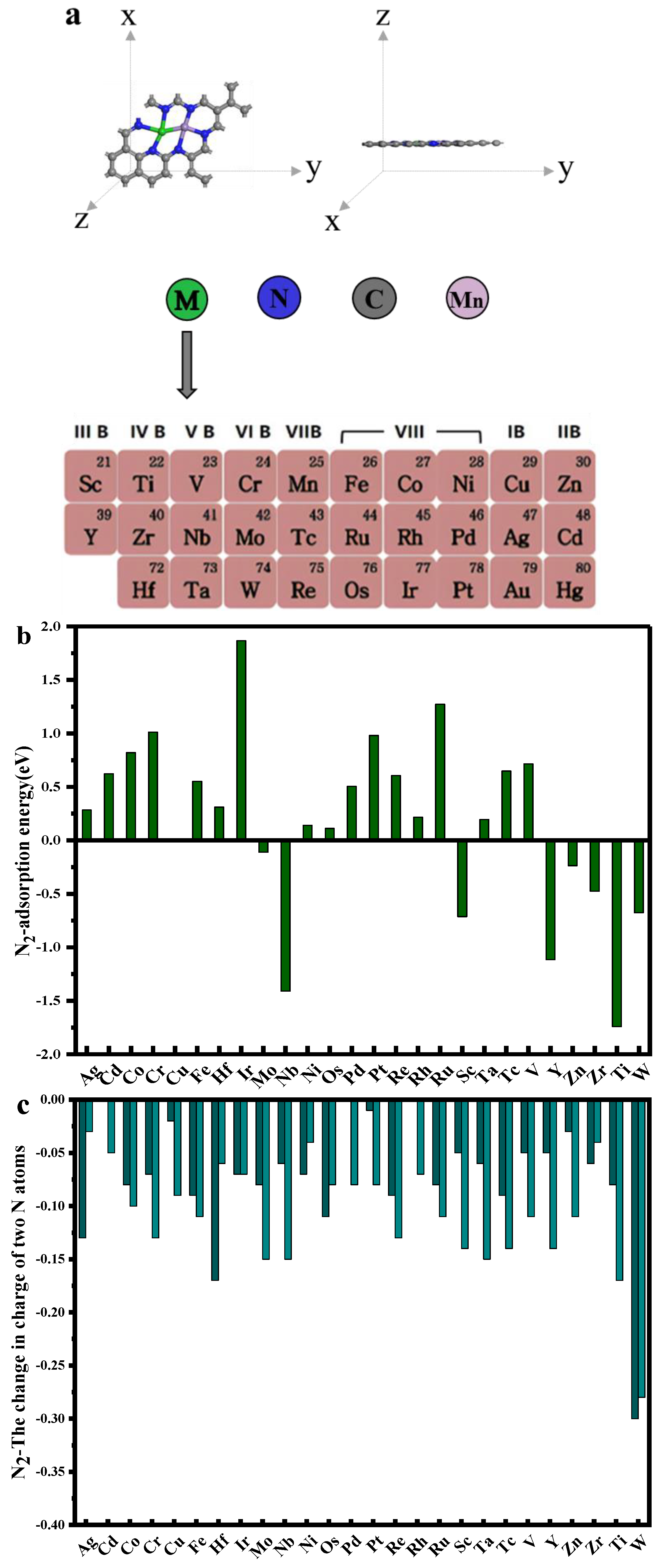
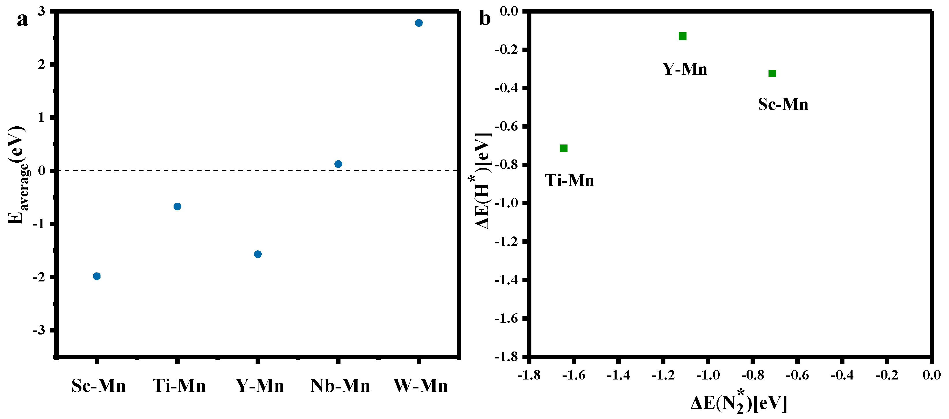
3.1. The Structures of Mn-M@N6-C (M = Sc, Ti, Y, Nb)

To assess the structural stability of the candidate, we calculate the average binding energy between the metal atom and the support average binding energy by formula [29]:
E f   = ( E M 2 N 6 E M 1 E M 2 E sub ) / 2
where E M 2 N 6 represents the total energy of the diatomic catalyst structure. The   E sub represents the energy of the N-doped graphene substrates;   E M 1 and E M 2 represent the energy of the two transition metal atoms. The average binding energies of different TM atoms embedded in N-doped graphene are compared in Figure 2. It was found that the Nb-Mn @N6-C value was greater than 0 and that Nb-Mn was bound by N atoms to graphene scaffolds; it is not a thermodynamically spontaneous process. As a result, we eliminated Nb-Mn@N6-C from the candidate catalysts and have not discussed them since. We reserved the three candidates Mn-M@N6-C (M = Sc, Ti, Y), and then analyzed only these three candidates.

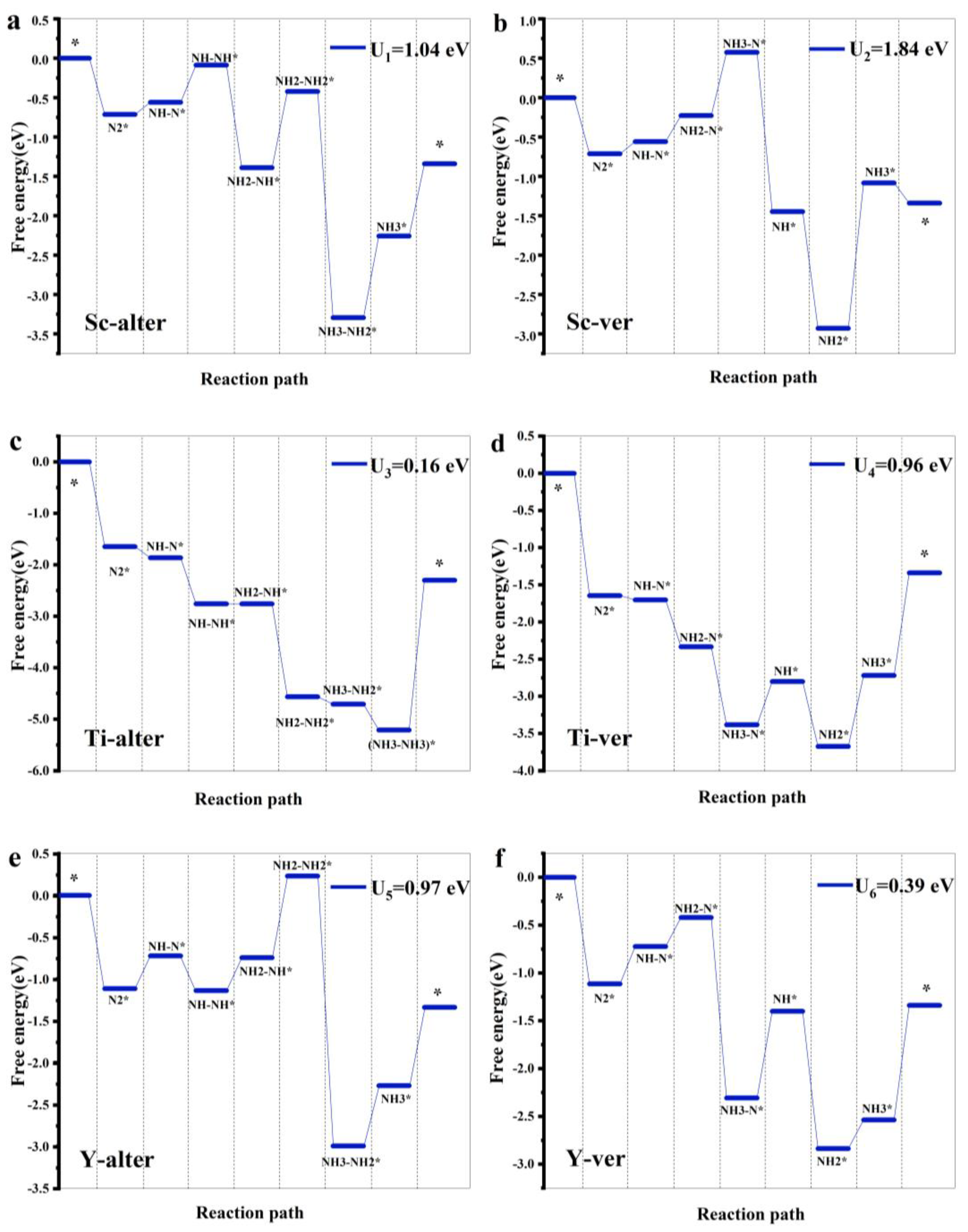
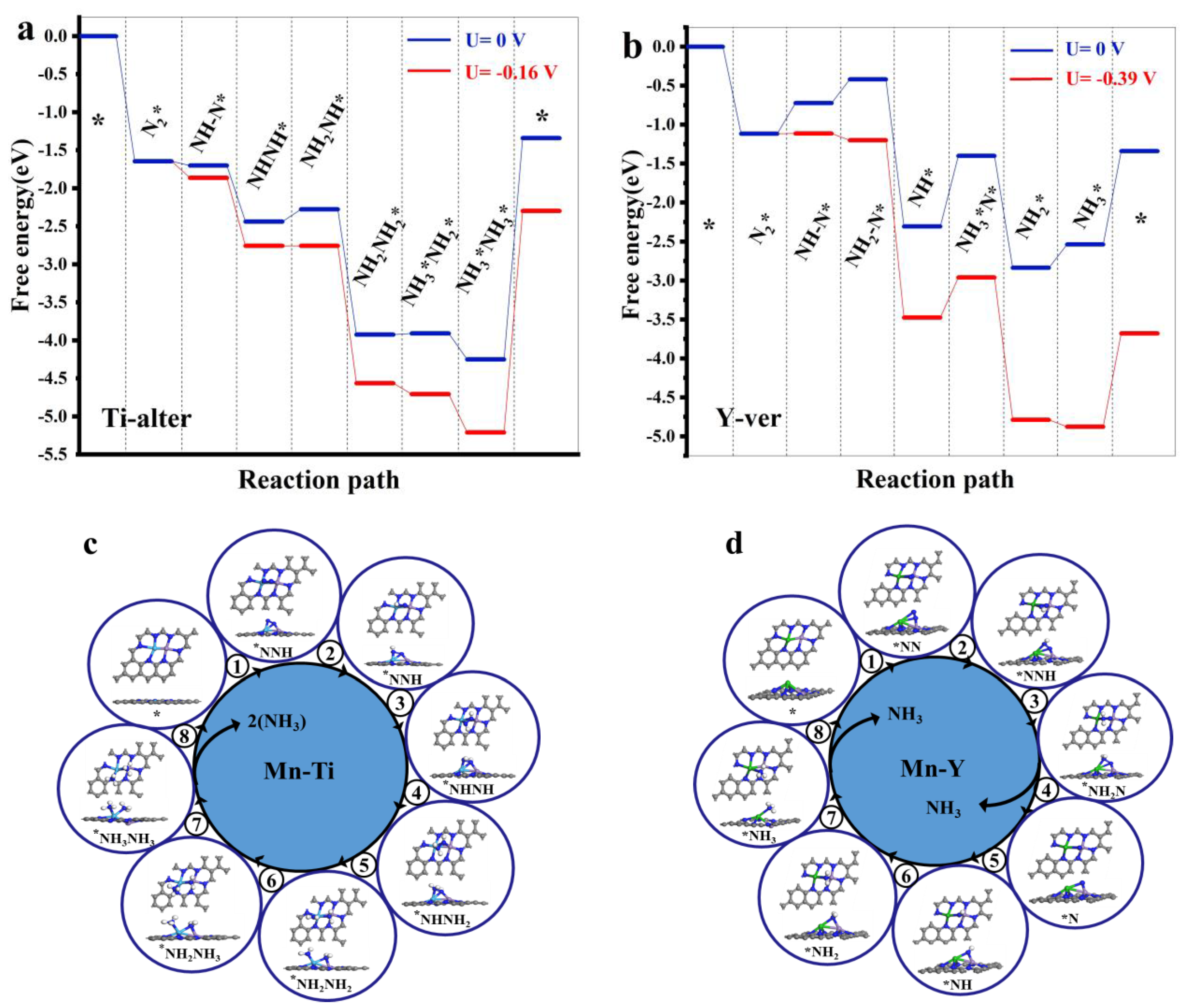
3.2. HER and NRR Path

Adsorption as a prerequisite for NRR is critical because the adsorption strength determines the subsequent electrochemical reduction reaction [20,30,31]. The adsorption configuration is also important because it determines the NRR mechanism. We performed separate Sc, Ti, Y-Mn@N6 bridge position and top position adsorption; it was found that horizontal adsorption at the bridge site is the most stable adsorption site. The adsorption energy of nitrogen was compared with the adsorption energy of H* at its most stable adsorption site, respectively, to meet the requirements of ΔG(H) > ΔG(N2); therefore, nitrogen occupies a stable site more easily than H*. Obviously, the adsorption free energy at the active site of Mn-M@N6-C (M = Sc, Ti, Y) is more negative than the H* free energy (Figure 3), indicating that the adsorption is more stable. Thus, the active site on Mn-M@N6-C (M = Sc, Ti, Y) can be promoted in terms of adsorption to inhibit the Hydrogen Evolution Reaction (HER). Mn-M@N6-C (M = Sc, Ti, Y) has good selectivity for the activation of N2. Note that the adsorbed N2 is easily activated.
In order to study the reaction process of NRR on the diatomic Mn-M@N6-C (M = Sc, Ti, Y), N2 adsorption was performed at the most stable adsorption site of Mn-M@N6-C (M = Sc, Ti, Y), and the free energy of each step of the alternating path and vertical path reaction was calculated (data see as Supplementary Materials). Figure 3a–f are schematic diagrams of their respective free energy pathways. The reaction path plot shows the free energy barrier of the basic reaction steps along different paths, comparing Figure 3a–f and finding Sc-Mn@N6. The limit potential of both mechanisms is greater than 1.0 eV, so Mn-M@N6-C (M = Sc) is screened out of the catalyst candidate.
The alternating path of Ti-Mn@N6-C was found to have the lowest limit potential of 0.16 eV, as shown in Figure 4a, so Ti-Mn@N6-C is an effective catalyst for promoting N2 reduction.
Figure 4b is the free energy reaction path diagram of Y-Mn@N6-C; it can be seen that the limit potential of the vertical mechanism of Y-Mn@N6-C is 0.39 eV; Y-Mn@N6-C is also an effective catalyst for promoting N2 reduction. The reason for these excellent properties is that each part of the catalytic system has excellent charge transfer ability during catalysis; the electronic structure of Mn-M@N6-C (M = Ti, Y) is then analyzed.

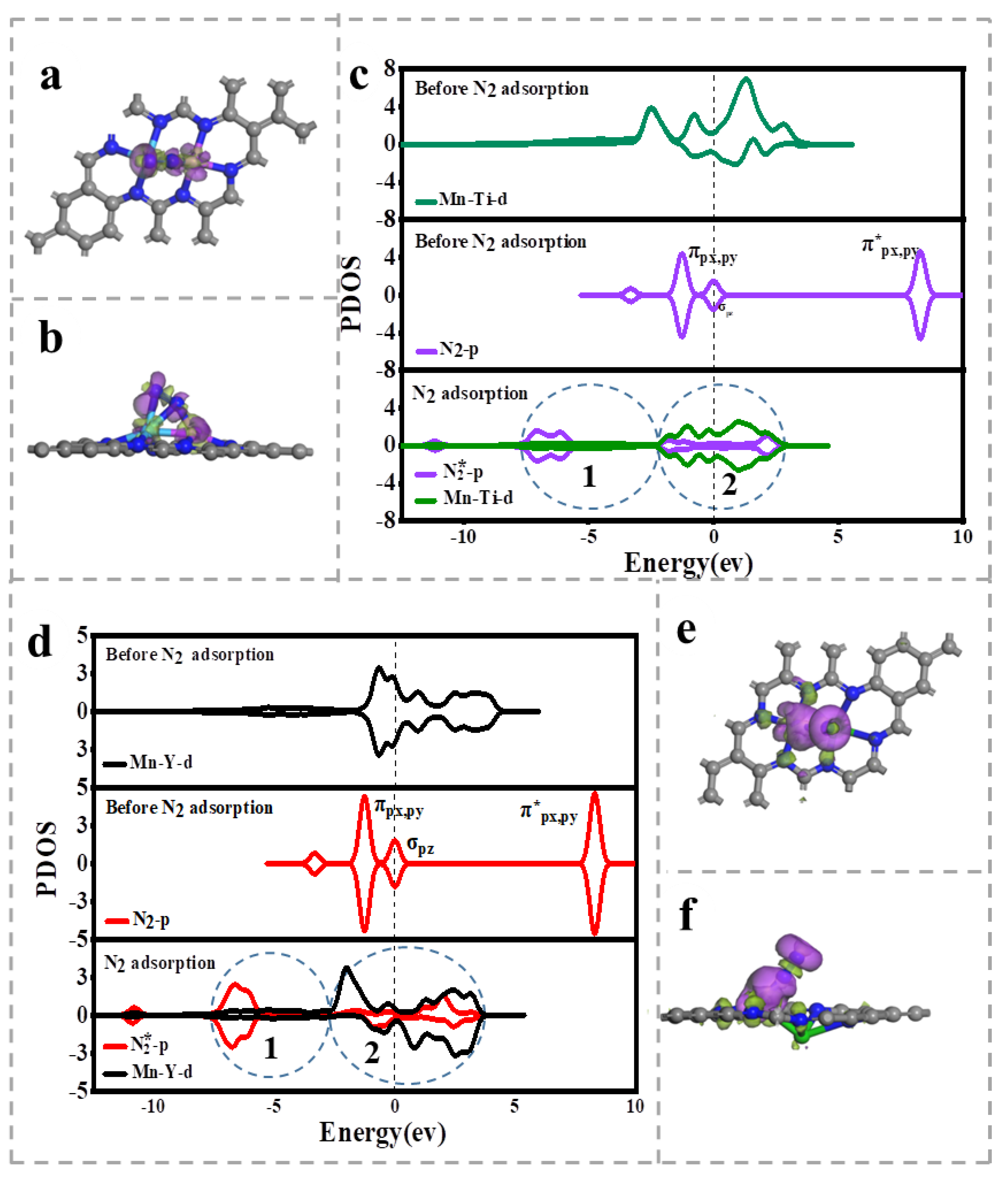
3.3. Charge Density Difference (CDD) and Projected Electron State Density (PDOS)

To further elucidate the excellent properties of diatomic Mn-M@N6-C (M = Ti, Y) for NRR, we analyzed the N2 adsorption difference in charge density across Mn-M@N6-C (M = Ti, Y).
Analyzing Figure 5a first, after adsorption on Ti-Mn@N6-C, a small number of electrons in the NN triple bond are transferred to the region around N and between the N-TM nucleus, especially to N-Ti, which shows that the electrons in the NN triple bond decrease, the bond length increases, and the NN triple bond strength decrease is activated. Figure 5b is the CDD of N2 adsorbed on Y-Mn@N6-C, with the yellow region representing the area where the electrons diverge and the purple region representing the area where the electrons are lost. Analyzing Figure 5b, after adsorptions on Y-Mn@N6-C, a small number of electrons in the N-N triple bond are transferred to the region around N and between the N-Mn nuclei observably. This shows that the electrons in the N-N triple bond decrease, the bond length increases, and the N-N triple bond strength decrease is activated.
Firstly, it can be observed that the peak value of the PDOS map of the 2p-orbital of N2 after N2 adsorption changes from regular to irregular, and the integral of the PDOS graph to the energy interval is the number of electrons, which proves that the electrons have changed from the previous regular distribution to irregular distribution, the electron distribution position is broken, the NN three bonds are destroyed and N2 is activated. We compare the d track of the catalyst to an electronic elevator, with the low-energy zone 1 and high-energy zone 2 representing the elevator entrance and elevator exit, respectively [10,32]. Specifically, the integration of the PDOS of Mn-Y and Mn-Ti in the low-energy interval 1 is higher than before adsorption, proving that the number of electrons in the d orbit of Mn-Y and Mn-Ti in energy interval 1 is higher than before adsorption. Therefore, energy interval 1 is relative to the elevator entrance, and at the elevator entrance electrons enter the d orbits of Mn-Y and Mn-Ti from the π p x , p y and σ p z tracks of N2, forming Mn-N, Ti-N and Y-N bonds, which strengthen the adsorption of N2, the integration of the PDOS of Mn-Y and Mn-Ti to the energy interval in the high-energy interval 2 is less than before adsorption, while the PDOS of the 2p-orbit of N2 increases the integration of the energy interval, so energy interval 2 is relative to the elevator exit; at the elevator exit, the number of electrons on the d orbit of Mn-Y and Mn-Ti decreases relative to before adsorption, the number of electrons in the π * -orbit of N2 increases relative to before adsorption and the electrons enter N2 by the d orbital of Mn-Y and Mn-Ti π p x , p y * . In this way, the d track completed a task of electronic transportation. The position of the π p x , p y * peak is significantly delocalized, resulting in its orbit being almost connected to the σ p z orbit. Therefore, the established Mn-M@N6-C (M = Ti, Y) catalyst has a particularly strong ability to adsorb and activate N2, preparing for the subsequent hydrogenation.
The above analysis of the difference between charge density and local electron state density shows that the Ti-Mn@N6-C and Y-Mn@N6-C catalysts can play the role of electron transport, filling electrons into the π * orbital of the N2, which has an excellent catalytic performance for N2 reduction.

4. Conclusions

In the text, we designed the Mn-M (M = Sc, Ti, Y, Nb) active site. We showed through calculations that graphene-supported Mn-M (M = Sc, Ti, Y) has stability and selectivity for NRR. The preferred response mechanism for NRR is the alternating path on Mn-Ti@N6, with a reaction limit potential of 0.16 eV. Mn-Y@N6 on the vertical path has a reaction limit potential of 0.39 eV. Importantly, the significant NRR performance on Mn-Y supported by graphene is that the Mn-Y active site as an electronic adapter can be activated by providing electrons, adjusting the charge transfer during NRR. In addition, the positive charge state of the Mn-Y active site can promote the adsorption and inhibition of HER to promote the formation of NRR.

Supplementary Materials

The following supporting information can be downloaded at: https://www.mdpi.com/article/10.3390/catal13010049/s1, Table S1: Alternate correction item (eV) at 289.15 K; Table S2: Alternate the free energy of each step (eV); Table S3: Change in free energy at alternate steps (eV); Table S4: Alternate Plotting value (eV); Table S5: Ti Alternate Plotting value (eV).

Author Contributions

Investigation, Data curation, Formal analysis, Writing—original draft, J.H.; Supervision, Validation, Writing—review & editing, C.H.; Data curation, Formal analysis, Visualization, Writing—review & editing, H.W.; Data curation, Formal analysis, Visualization, Writing, K.Z.; Data curation, Formal analysis, C.Z. All authors have read and agreed to the published version of the manuscript.

Funding

This research was funded by the Natural Science Basic Research Program of Shaanxi (Program Nos. 2022JQ-108, 2022JQ-096).

Data Availability Statement

The data that support the findings of this study are available from the corresponding author upon reasonable request.

Conflicts of Interest

The authors declare no conflict of interest.

References

  1. Zhang, Y.L.; Liu, H.; Li, J.J.; Deng, Y.L.; Miao, X.P.; Xu, D.P.; Liu, S.Q.; Xie, K.C.; Tian, Y.J. Life cycle assessment of ammonia synthesis in China. Int. J. Life Cycle Assess. 2022, 27, 50–61. [Google Scholar] [CrossRef]
  2. Cai, X.X.; Luo, G.Y.; Li, Z.Q.; He, Y. Optical conductivity of twisted bilayer graphene under heterostrain. Acta Phys. Sin. 2021, 70, 187301. [Google Scholar] [CrossRef]
  3. Tiwari, S.K.; Sahoo, S.; Wang, N.; Huczko, A. Graphene research and their outputs: Status and prospect. J. Sci. Adv. Mater. Devices 2020, 5, 10–29. [Google Scholar] [CrossRef]
  4. Hu, X.; Xiong, L.; Fang, W.-H.; Su, N.Q. Computational Insight into Metallated Graphynes as Single Atom Electrocatalysts for Nitrogen Fixation. ACS Appl. Mater. Interfaces 2022, 14, 27861–27872. [Google Scholar] [CrossRef]
  5. Yang, W.; Xu, S.; Ma, K.; Wu, C.; Gates, I.D.; Ding, X.; Meng, W.; Gao, Z. Geometric structures, electronic characteristics, stabilities, catalytic activities, and descriptors of graphene-based single-atom catalysts. Nano Mater. Sci. 2020, 2, 120–131. [Google Scholar] [CrossRef]
  6. Tang, Y.; Chen, W.; Zhou, J.; Chai, H.; Li, Y.; Cui, Y.; Feng, Z.; Dai, X. Mechanistic insight into the selective catalytic oxidation for NO and CO on co-doping graphene sheet: A theoretical study. Fuel 2019, 253, 1531–1544. [Google Scholar] [CrossRef]
  7. Tang, Y.; Chen, W.; Shen, Z.; Chang, S.; Zhao, M.; Dai, X. Nitrogen coordinated silicon-doped graphene as a potential alternative metal-free catalyst for CO oxidation. Carbon 2017, 111, 448–458. [Google Scholar] [CrossRef]
  8. Zhou, Y.; Yu, X.; Sun, F.; Zhang, J. MoP supported on reduced graphene oxide for high performance electrochemical nitrogen reduction. Dalton Trans. 2020, 49, 988–992. [Google Scholar] [CrossRef]
  9. Wang, W.; Wang, X.; Sun, Y.; Tian, Y.; Liu, X.; Chu, K.; Li, J. Ultrasmall iridium nanoparticles on graphene for efficient nitrogen reduction reaction. New J. Chem. 2022, 46, 5464–5469. [Google Scholar] [CrossRef]
  10. Wang, F.; Wei, X.; Mao, J. Graphene with SiC3 ligand for N2 to NH3 reduction with an ultralow overpotential of 0.03 V. J. Electroanal. Chem. 2022, 904, 115953. [Google Scholar] [CrossRef]
  11. Wang, F.; Mao, L.; Xie, H.; Mao, J. Graphene Derivatives and Graphene Composite Electrocatalysts for N-2 Reduction Reaction. Small Struct. 2021, 2, 2000075. [Google Scholar] [CrossRef]
  12. Huang, H.; Gong, F.; Wang, Y.; Wang, H.; Wu, X.; Lu, W.; Zhao, R.; Chen, H.; Shi, X.; Asiri, A.M.; et al. Mn3O4 nanoparticles@reduced graphene oxide composite: An efficient electrocatalyst for artificial N-2 fixation to NH3 at ambient conditions. Nano Res. 2019, 12, 1093–1098. [Google Scholar] [CrossRef]
  13. Chen, Z.W.; Yan, J.M.; Jiang, Q. Single or Double: Which Is the Altar of Atomic Catalysts for Nitrogen Reduction Reaction? Small Methods 2018, 3, 1800291. [Google Scholar] [CrossRef]
  14. Wang, J.; He, C.; Huo, J.; Fu, L.; Zhao, C. A Theoretical Evaluation of Possible N2 Reduction Mechanism on Mo2B2. Adv. Theory Simul. 2021, 4, 2100003. [Google Scholar] [CrossRef]
  15. Yu, J.; He, C.; Huo, J.; Zhao, C.; Yu, L. Electric field controlled CO2 capture and activation on BC6N monolayers: A first-principles study. Surf. Interfaces 2022, 30, 101885. [Google Scholar] [CrossRef]
  16. Zhang, Q.; He, C.; Huo, J. Mechanism of complete dehydrogenation of ammonia borane in electrochemical alkaline environment. Comput. Mater. Sci. 2022, 207, 111306. [Google Scholar] [CrossRef]
  17. He, C.; Wang, J.; Fu, L.; Zhao, C.; Huo, J. Associative vs. dissociative mechanism: Electrocatalysis of nitric oxide to ammonia. Chin. Chem. Lett. 2022, 33, 1051–1057. [Google Scholar] [CrossRef]
  18. Wang, R.; He, C.; Chen, W.; Fu, L.; Zhao, C.; Huo, J.; Sun, C. Design strategies of two-dimensional metal-organic frameworks toward efficient electrocatalysts for N2 reduction: Cooperativity of transition metals and organic linkers. Nanoscale 2021, 13, 19247–19254. [Google Scholar] [CrossRef]
  19. He, C.; Wang, H.; Fu, L.; Huo, J.; Zheng, Z.; Zhao, C.; An, M. Principles for designing CO2 adsorption catalyst: Serving thermal conductivity as the determinant for reactivity. Chin. Chem. Lett. 2022, 33, 990–994. [Google Scholar] [CrossRef]
  20. Zheng, G.; Li, L.; Tian, Z.; Zhang, X.; Chen, L. Heterogeneous single-cluster catalysts (Mn3, Fe3, Co3, and Mo3) supported on nitrogen-doped graphene for robust electrochemical nitrogen reduction. J. Energy Chem. 2021, 54, 612–619. [Google Scholar] [CrossRef]
  21. Song, W.; Xie, K.; Wang, J.; Guo, Y.; He, C.; Fu, L. Density functional theory study of transition metal single-atoms anchored on graphyne as efficient electrocatalysts for the nitrogen reduction reaction. Phys. Chem. Chem. Phys. 2021, 23, 10418–10428. [Google Scholar] [CrossRef] [PubMed]
  22. He, C.; Sun, R.; Fu, L.; Huo, J.; Zhao, C.; Li, X.; Song, Y.; Wang, S. Defect engineering for high-selection-performance of NO reduction to NH3 over CeO2 (111) surface: A DFT study. Chin. Chem. Lett. 2022, 33, 527–532. [Google Scholar] [CrossRef]
  23. Zhao, C.; Xi, M.; Huo, J.; He, C. B-Doped 2D-InSe as a bifunctional catalyst for CO2/CH4 separation under the regulation of an external electric field. Phys. Chem. Chem. Phys. 2021, 23, 23219–23224. [Google Scholar] [CrossRef] [PubMed]
  24. Zhao, C.; Xi, M.; Huo, J.; He, C.; Fu, L. Electro-reduction of N2 on nanostructured materials and the design strategies of advanced catalysts based on descriptors. Mater. Today Phys. 2022, 22, 100609. [Google Scholar] [CrossRef]
  25. Qin, Y.; Zhang, S.; Gao, G.; Ding, S.; Su, Y. A theoretical study on molybdenum and sulfur co-doped graphene for electrocatalytic nitrogen reduction. Mol. Catal. 2022, 517, 112048. [Google Scholar] [CrossRef]
  26. Liu, G.; Niu, L.; Ma, Z.; An, L.; Qu, D.; Wang, D.; Wang, X.; Sun, Z. Fe2Mo3O8/XC-72 electrocatalyst for enhanced electrocatalytic nitrogen reduction reaction under ambient conditions. Nano Res. 2022, 15, 5940–5945. [Google Scholar] [CrossRef]
  27. Liao, Y.; Ye, W.; Zhu, Y.; Wang, L. Ultrathin MoS2 Nanosheets for Electrocatalytic N-2-To-NH3 Fixation Under Ambient Conditions. Int. J. Electrochem. Sci. 2020, 15, 11555–11566. [Google Scholar] [CrossRef]
  28. Ball, B.; Das, P.; Sarkar, P. Molybdenum Atom-Mediated Salphen-Based Covalent Organic Framework as a Promising Electrocatalyst for the Nitrogen Reduction Reaction: A First-Principles Study. J. Phys. Chem. C 2021, 125, 26061–26072. [Google Scholar] [CrossRef]
  29. Huo, J.; Wei, H.; Fu, L.; Zhao, C.; He, C. Highly active Fe36Co44 bimetallic nanoclusters catalysts for hydrolysis of ammonia borane: The first-principles study. Chin. Chem. Lett. 2022. [Google Scholar] [CrossRef]
  30. Song, W.; Fu, Z.; Liu, X.; Guo, Y.; He, C.; Fu, L. Density functional theory study of a two-atom active site transition-metal/iridium electrocatalyst for ammonia synthesis. J. Mater. Chem. A 2022, 10, 13946–13957. [Google Scholar] [CrossRef]
  31. Guo, X.; Gu, J.; Lin, S.; Zhang, S.; Chen, Z.; Huang, S. Tackling the Activity and Selectivity Challenges of Electrocatalysts toward the Nitrogen Reduction Reaction via Atomically Dispersed Biatom Catalysts. J. Am. Chem. Soc. 2020, 142, 5709–5721. [Google Scholar] [CrossRef] [PubMed]
  32. Xue, Z.; Zhang, X.; Qin, J.; Liu, R. Anchoring Mo on C9N4 monolayers as an efficient single atom catalyst for nitrogen fixation. J. Energy Chem. 2021, 57, 443–450. [Google Scholar] [CrossRef]
Figure 1. (a) Prototype of two-dimensional M2-N6@ graphene; (b) Comparison of the adsorption energy of N2 on different metal catalyst candidates; (c) Adsorption of different metal catalyst candidates; the charge of the last two N atoms changes. (d) On different metal catalyst candidates, comparison of bond length variations.
Catalysts 13 00049 g001aCatalysts 13 00049 g001b
Figure 2. (a) Different TMs embedded in N-doped graphene comparison plot of the average binding energy of atoms; (b) Comparison of adsorption energies of electron-coupled protons and free N2 molecules.
Catalysts 13 00049 g002
Figure 3. (a) Path diagram of the free energy reaction path of NRR alternating mechanism on Sc-Mn-N6; (b) Path diagram of the free energy reaction of NRR vertical mechanism on Sc-Mn-N6; (c) Path diagram of the free energy reaction path of NRR alternating mechanism on Ti-Mn-N6; (d) Free energy reaction path diagram of the vertical mechanism of NRR on Ti-Mn-N6; (e) Free energy reaction path diagram of NRR alternating mechanism on Y-Mn-N6; (f) Path map of the free energy reaction path of the NRR vertical mechanism on Y-Mn-N6. * in the Figure represent adsorbed structure.
Catalysts 13 00049 g003
Figure 4. (a) The NRR free energy reaction path diagram of Ti-Mn@N6-C; (b) NRR free energy reaction path diagram of Y-Mn@N6-C; (c) Reflects the optimized top and side views on Ti-Mn@N6-C; (d) Reflects the optimized top and side views on Y-Mn@N6-C.
Catalysts 13 00049 g004
Figure 5. (a,b) N2 differential plot of charge density adsorbed on Ti-Mn@N6-C; The purple and yellow surfaces represent the enrichment and depletion of electrons, respectively; (c) The PDOS of p-orbital of free (N2-p) and adsorbed (N2*-p) N2 molecule, d-orbital of Mn and Y atoms (MnY-d) on Mn-Y@N6-C before and after N2 adsorption; (d) The PDOS of p-orbital of free (N2-p) and adsorbed (N2*-p)N2 molecule, d-orbital of Mn and Ti atoms (Mn-Ti-d) on Mn-Ti@N6-C before and after N2 adsorption; (e,f) the CDD of N2 adsorbed on Y-Mn@N6-C. The purple and yellow surfaces represent the enrichment and depletion of electrons, respectively.
Catalysts 13 00049 g005
Disclaimer/Publisher’s Note: The statements, opinions and data contained in all publications are solely those of the individual author(s) and contributor(s) and not of MDPI and/or the editor(s). MDPI and/or the editor(s) disclaim responsibility for any injury to people or property resulting from any ideas, methods, instructions or products referred to in the content.

